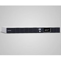
OR1000ERM1U - Uninterruptible power supply CyberPower - Free user manual and instructions
Find the device manual for free OR1000ERM1U CyberPower in PDF.


| Product Type | Uninterruptible Power Supply (UPS) |
| Brand | CyberPower |
| Model | OR1000ERM1U |
| Capacity (VA) | 1000 VA |
| Capacity (Watts) | 600 W |
| Input Voltage | 165 VAC ~ 271 VAC |
| Input Frequency | 50/60 Hz (Auto Detection) |
| Battery Output Voltage | Simulated Sine Wave at 230 VAC ± 10% |
| Transfer Time | 4 ms (Typical) |
| Number of Output Outlets | 6 x IEC320 C13 (4 Battery Backup Outlets + 2 Surge Protection Only Outlets) |
| Surge Protection | 1030 Joules, RJ11/RJ45 Protection (1 Input / 1 Output) |
| Battery Type | Maintenance-free Sealed Lead-Acid, 6V / 7Ah x4 |
| Runtime (Estimated) | Varies by load (see PowerPanel software) |
| Charge Time | 8 hours typical |
| Dimensions (W x D x H) | 43.3 x 38.9 x 4.4 cm (1U Rack) |
| Weight | 13.7 kg |
| Operating Temperature | 0 °C to 40 °C |
| Relative Humidity | 0% to 90% (non-condensing) |
| Management Software | PowerPanel® Business (Windows, Mac, Linux) |
| Communication | USB, DB-9 Serial Port, optional SNMP/HTTP via optional card |
| Display | High Resolution Digital LCD Screen |
| Special Features | Automatic Voltage Regulation (AVR), GreenPower Technology, Self-Test, Auto Restart |
| Maintenance | User-replaceable battery, recharge every 3 months in storage |
| Safety | Overload Circuit Breaker, Short Circuit Protection, do not use with medical or laser equipment |
Frequently Asked Questions - OR1000ERM1U CyberPower
User questions about OR1000ERM1U CyberPower
0 question about this device. Answer the ones you know or ask your own.
Ask a new question about this device
Download the instructions for your Uninterruptible power supply in PDF format for free! Find your manual OR1000ERM1U - CyberPower and take your electronic device back in hand. On this page are published all the documents necessary for the use of your device. OR1000ERM1U by CyberPower.
USER MANUAL OR1000ERM1U CyberPower
natural_image
Isometric line drawing of a rectangular electronic device with ventilation slots and a central hub (no text or symbols)OR1000ERM1U/OR1500ERM1U User's Manual
IMPORTANT SAFETY INSTRUCTIONS
This manual contains important instructions that should be followed during installation and maintenance of the UPS and batteries. Please read and follow all instructions carefully during installation and operation of the unit. Read this manual thoroughly before attempting to unpack, install, or operate.
CAUTION! The UPS must be connected to a grounded AC power outlet with fuse or circuit breaker protection. DO NOT plug the UPS into an outlet that is not grounded. If you need to de-energize this equipment, turn off and unplug the UPS.
CAUTION! DO NOT USE FOR MEDICAL OR LIFE SUPPORT EQUIPMENT! CyberPower Systems does not sell products for life support or medical applications. DO NOT use in any circumstance that would affect the operation or safety of any life support equipment, with any medical applications, or patient care.
CAUTION! The battery can energize hazardous live parts inside even when the AC input power is disconnected.
CAUTION! To prevent the risk of fire or electric shock, install in a temperature and humidity controlled indoor area, free of conductive contaminants. (Please see specifications for acceptable temperature and humidity range).
CAUTION! To reduce the risk of electric shock, do not remove the cover, except to service the battery. There are no user serviceable parts inside, except for the battery.
CAUTION! To avoid electrical shock, turn off the unit and unplug it from the AC power source before servicing the battery or installing a computer component.
CAUTION! DO NOT USE WITH OR NEAR AQUARIUMS! To reduce the risk of fire, do not use with or near aquariums. Condensation from the aquarium can come in contact with metal electrical contacts and cause the machine to short out.
CAUTION! DO NOT USE WITH LASER PRINTERS! The power demands of laser printers are too large for a UPS.
INSTALLING YOUR UPS SYSTEM
UNPACKING
The box should contain the following:
(1) USB cable (A+B type) (2) User manual (3) UPS unit (4) power cord x 4
*PowerPanel® Business software is available on our website.
Please visit www.cyberpower.com and go to the Software Section for free download.
OVERVIEW
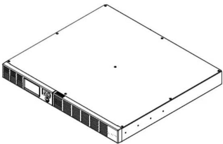
The OR1000ERM1U/OR1500ERM1U provides automatic voltage regulation for inconsistent utility power. The OR1000ERM1U/OR1500ERM1U features 1030 Joules of surge protection, and provides battery backup during power outages. The OR1000ERM1U/OR1500ERM1U ensures consistent power to your computer system and its included software will automatically save your open files and shutdown your computer system during a utility power loss.
HOW TO DETERMINE THE POWER REQUIREMENTS OF YOUR EQUIPMENT
-
Make sure that the total Volt-Amp (VA) requirements of your computer, monitor, and peripheral equipment does not exceed 1000VA/1500VA.
-
Ensure that the equipment plugged into the four battery power-supplied/surge outlets does not exceed the UPS unit's rated capacity (1000VA/600W for OR1000ERM1U, 1500VA
/900W for OR1500ERM1U). If the rated unit capacities are exceeded, an overload condition may occur and cause the UPS unit to shut down and the circuit breaker to trip.
- If the power requirements of your equipment are listed in units other than Volt-Amps (VA), convert Watts (W) or Amps (A) into VA by performing the calculations below.
Note: The equation listed below only calculates the maximum amount of VA that the equipment can use, not what is typically used by the equipment at given time. Users should expect usage requirements to be approximately 60% of the maximum power requirements:
Watts (W) x 1.67 = VA or Amps (A) x 230 = VA
Add the totals up for all pieces of equipment and multiply this total by 0.6 to calculate the approximate requirements.
There are many factors that can affect the amount of power that your computer system will require. The total load that you will be placing on the battery-powered outlets should not exceed 80% of the unit's capacity.
BASIC OPERATION
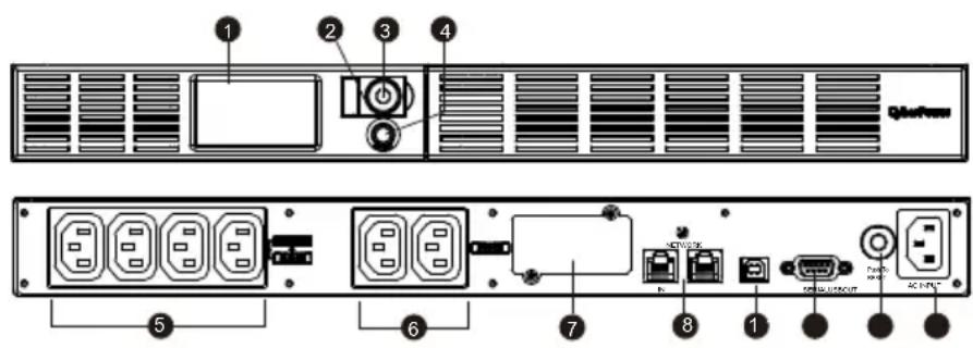
DESCRIPTION
1. LCD module display
LCD shows all the UPS information with icons and messages.
2. Power on LED
This LED is illuminated when the utility condition is normal and the UPS outlets are providing power, free of surges and spikes.
3. Power Switch
Master on/off switch for equipment connected to the battery power supplied outlets.
4. LCD function selected switch
The switch can be used to select the LCD display contents Including input/output voltage and estimated run time, etc.
5. Battery, Surge and AVR Outlets
Provides four battery power, surge protected and AVR outlets for connected equipment and ensures temporary uninterrupted operation of your equipment during a power failure.
6. Surge Outlets
Provides two surge protected outlets for connected equipment.
7. Expansion Port
Allows users to add the optional SNMP card.
8. Communication Protection Ports
Communication protection ports will protect any standard modem, fax, telephone line, broadband network or Ethernet connection.
9. USB Port to PC
The USB port allow communication from the UPS to the computer. The UPS communicates its status to the PowerPanel® Business software when connected with a USB port.
10. Serial Port to PC
The port allows connection and communications from the DB-9 serial on the computer to the UPS unit.
11. Circuit Breaker
Located on the side of the UPS, the circuit breaker serves to provide overload and fault protection.
12. AC Input
Connect the AC Power cord to a properly wired and grounded outlet.
Hardware Installation Guide
-
Your new UPS may be used immediately upon receipt. However, recharging the battery for at least 8 hours is recommended to ensure that the battery's maximum charge capacity is achieved. Charge loss may occur during shipping and storage. To recharge the battery, simply leave the unit plugged into an AC outlet. The unit will charge in both the on and off position.
-
If you will use the software, connect the USB cable to the USB port on the UPS.
-
With the UPS unit off and unplugged, connect the computer, monitor, and any externally powered data storage device (Zip drive, Jazz drive, Tape drive, etc. into the battery power supplied outlets. DO NOT plug a laser printer, copier, space heater, vacuum, paper shredder or other large electrical device into the UPS. The power demands of these devices will overload and possibly damage the unit.
-
To protect a fax, telephone, modem line or network cable, connect a telephone cable or network cable from the wall jack outlet to the IN jack of the UPS. Then connect a telephone cable or network cable from the OUT jack on the UPS to the modem, computer, telephone, fax machine, or network device.
-
Plug the UPS into a 2 pole, 3 wire grounded receptacle (wall outlet). Make sure the wall branch outlet is protected by a fuse or circuit breaker and does not service equipment with large electrical demands (e.g. air conditioner, refrigerator, copier, etc. Avoid using extension cords. If used, the extension cord must be grounded and rated for 15 amps.
-
Depress the power switch to turn the unit on. The power on indicator light will illuminate and the unit will "beep" once.
-
If an overload is detected, an audible alarm will sound and the unit will emit one long beep. To correct this, turn the UPS off and unplug at least one piece of equipment from the battery power supplied outlets. Wait 10 seconds. Make sure the circuit breaker is depressed and then turn the UPS on.
-
Your UPS is equipped with an auto-charge feature. When the UPS is plugged into an AC outlet, the battery will automatically recharge.
-
To maintain optimal battery charge, leave the UPS plugged into an AC outlet at all times. 10. To store your UPS for an extended period, cover it and store with the battery fully charged. Recharge the battery every three months to ensure battery life.
BATTERY REPLACEMENT
CAUTION! Read and follow the IMPORTANT SAFETY INSTRUCTIONS before servicing the battery. Service the battery under the supervision of personnel knowledgeable of batteries and their precautions.
CAUTION! Use only the specified type of battery. See your dealer for replacement batteries. CAUTION! The battery may present the risk of electrical shock. Do not dispose of batteries in a fire, as they may explode. Follow all local ordinances regarding proper disposal of batteries. CAUTION! Do not open or mutilate the batteries. Released electrolyte is harmful to the skin and eyes and may be toxic.
CAUTION! A battery can present a high risk of short circuit current and electrical shock. Take the following precautions before replacing the battery:
- Remove all watches, rings or other metal objects.
- Only use tools with insulated handles.
- DO NOT lay tools or other metal parts on top of battery or any battery terminals.
- Wear rubber gloves and boots.
- Determine if the battery is inadvertently grounded. If inadvertently grounded, remove source of ground. CONTACT WITH A GROUNDED BATTERY CAN RESULT IN
ELECTRICAL SHOCK! The likelihood of such shock will be reduced if such grounds are removed during installation and maintenance (applicable to a UPS and a remote battery supply not having a grounded circuit)
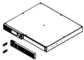
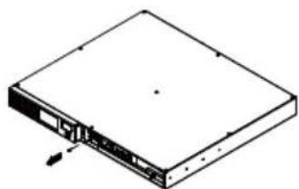
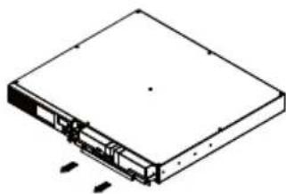
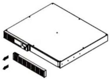
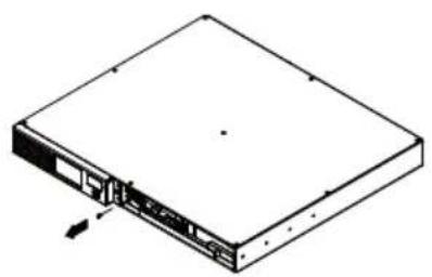
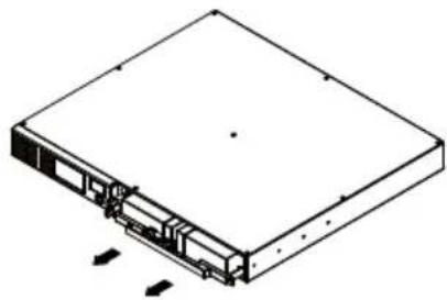
BATTERY REPLACEMENT PROCEDURE:
natural_image
Isometric line drawing of a rectangular electronic device with a separate slot and two arrows indicating motion (no text or symbols)
natural_image
Isometric line drawing of a rectangular electronic device with internal components and mounting holes (no text or symbols)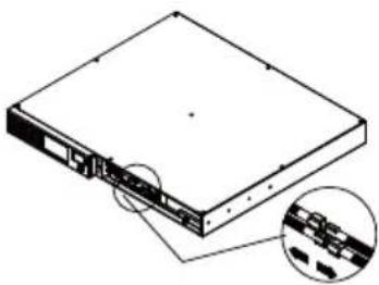
natural_image
Diagram of a rectangular electronic device with an inset close-up showing internal components (no text or symbols)-
Remove the right-side of the faceplate.
-
Remove the three retaining screws on the cable protection cover then remove the cover faceplate.
-
Disconnect the black and red cables.
natural_image
Isometric line drawing of a rectangular electronic device with internal components and mounting holes (no text or symbols)- Remove the retaining screw cover of the cable connectors.
natural_image
Isometric line drawing of a rectangular electronic device with internal components and mounting holes (no text or symbols)- Replace the new battery pack. Assemble the screws, cable and front panel in the reserve sequence of above steps. Recharge the unit for 4-8 hours to ensure the UPS performs expected runtime.
TROUBLE SHOOTING
| Problem Possible Cause Solution | ||
| Full-time surge protection outlets stop providing power to equipment. | Circuit breaker has tripped due to an overload. | Turn the UPS off and unplug at least one piece of equipment. Wait 10 seconds, reset the circuit breaker by depressing the button, and then turn the UPS on. |
| The UPS does not perform expected runtime. | Battery not fully charged. Recharge the battery by leaving the UPS plugged in. | |
| Battery is slightly worn out. | Contact CyberPower Systems about replacement batteries at service@cyberpower-eu.com | |
| The UPS will not turn on. | The on/off switch is designed to prevent damage by rapidly turning it off and on. | Turn the UPS off. Wait 10 seconds and then turn the UPS on. |
| The battery is worn out. | Contact CyberPower Systems about replacement batteries at service@cyberpower-eu.com | |
| Mechanical problem. Contact CyberPower Systems at service@cyberpower-eu.com | ||
| PowerPanel® Business is inactive. | The serial/USB cable is not connected. | Connect the serial/USB cable to the UPS unit and an open serial port on the back of the computer. You must use the cable that came with the unit. |
| The unit is not providing battery power. | Shutdown your computer and turn the UPS off. Wait 10 seconds and turn the UPS back on. This should reset the unit. | |
Additional troubleshooting information can be found at eu.cyberpowersystems.com
CYBERPOWER GREENPOWER UPS™ TECHNOLOGY
Advanced Energy-Saving Patented Bypass Technology
CyberPower's patented GreenPower UPS ^TM with Bypass Technology reduces UPS energy costs by up to 75% compared to conventional UPS models. Even when utility power is normal, conventional UPS models constantly pass power through a transformer. By contrast, under normal conditions the advanced circuitry of a GreenPower UPS ^TM bypasses the transformer. As a result, the power efficiency is significantly increased while decreasing waste heat, using less energy, and reducing energy costs.

When an abnormal power condition occurs, the GreenPower UPS™ automatically runs power through its transformer to regulate voltage and provide “safe” power. Since utility power is normal over 88% of the time, the GreenPower UPS™ operates primarily in its efficient bypass mode. The GreenPower UPS™ is also manufactured in accordance with the Restriction on Hazardous Substances (RoHS) directive making it one of the most environmentally-friendly on the market today.
TECHNICAL SPECIFICATIONS
| Model OR1000ERM1U OR1500ERM1U | ||
| Capacity (VA) | 1000VA | 1500VA |
| Capacity (Watts) | 600W | 900W |
| Input | ||
| Input Voltage Range 165VAC~271VAC | ||
| Frequency Range | 50/60Hz +/-3Hz(Auto Sensing) | |
| Output | ||
| On Battery Output Voltage | Simulated Sine Wave at 230Vac +/-10% | |
| On Battery Output Frequency | 50/60 Hz | |
| Transfer Time | 4ms Typical | |
| Overload Protection | On Utility: Circuit Breaker, On Battery: Internal Current Limiting | |
| Surge Protection | ||
| Lightning / Surge Protection | Yes | |
| Network/ Phone/ Fax/ Modem Protection | RJ11/RJ45 ( One In/ One Out ) | |
| Operating Temperature | +32°F to 104°F ( 0°C to 40°C ) | |
| Physical | ||
| Total # of UPS Receptacles | IEC320 C 13 x 6 ( Backup x 4 ) | |
| Maximum Dimensions(cm) | 1U Rack 43.3 x 38.9 x 4.4 | 1U Rack 43.3 x 38.9 x 4.4 |
| Weight (kg) | 13.7 kg | 14.9 kg |
| Battery | ||
| Sealed Maintenance Free Lead Acid Battery | 6V / 7Ah x4 6V / 9Ah x4 | |
| Typical Recharge Time 8 Hours | ||
| Charging Current(Max.) | 1A | |
| User Replaceable Yes | ||
| Status Indicators | ||
| Indicators Power On, Wiring | Fault, LCD Display | |
| Audible Alarms | On Battery, Low Battery, Overload | |
| Communication | ||
| PowerPanel® Business Software | Windows 2000/NT/XP/Vista,Mac OSX,Linux | |
| Management | ||
| Self -Test Yes | ||
| Auto-Charger | Yes | |
| Auto-Restart Yes | ||
| USB interface | Yes | |
| Dry contact Closure Yes | ||
| SNMP/HTTP Networking | Optional | |
FUNCTION SETUP GUIDE
 | Power On:Press and hold the POWER button. You will hear a constant tone for 1 second, followed by a short beep. Release the button after the short beep.Power Off:Press and hold the POWER button. You will hear a constant tone for 1 second, followed by two short beeps. Release the button after the two short beeps. |
LCD Display Toggle/Selected Switch | Enter Setup Mode:Press the select button for approximately 3 seconds to access the 11 functions of the setup mode: Local Power Quality, High Transfer Voltage, Low Transfer Voltage, Sensitivity, Low Battery Warning, Self Test, Buzzer Setting, LCD Sleep, Last Fault Reason, Back to default, Escape item.Select Function:Short press the toggle to switch from the current item to the next item.Confirm Option:When an option is selected, press the toggle for 3 seconds. The icons will stop flashing after the setting has been confirmed |
| Function | LCD Display | Options | Default | Description |
| Local Power Quality | Low | NormalHighCustomer(CUS)*Only when high/ low transfer voltage is configured | Normal(195V-257V) | This function determines how the UPS switch to Battery Mode.3 different output voltage ranges can be chosen according to the quality of the AC utility service in your location.If your utility service is not stable, you can select Low (189V~271V). The UPS will go to Battery Mode less often to tolerate the utility power fluctuations.If your utility service is stable, you can select High (207V~253V). The unit will go to Battery Mode more often. |
| High Transfer Voltage | 253V-271V 257V In Local Power Quality | settings, 10 fixed voltage ranges can be chosen. However, you can fine tune the High Transfer Voltage in this function. | ||
| If the utility voltage is usually high, and the connected equipment can work in this condition, you can set the output voltage range higher to reduce the UPS from going to Battery Mode as often. | ||||
| Low Transfer Voltage | 189V-207V 195V In Local Power Quality | settings, 10 fixed voltage ranges can be chosen. However, you can fine tune the Low Transfer Voltage in this function.If the utility voltage is usually low, and the connected equipment can work in this condition, you can set the output voltage range lower to reduce the UPS from going to AVR Mode or Battery Mode as often. | ||
| Sensitivity | 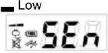 | 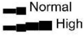 | Normal If the connected equipment can tolerate more power events (Example: unstable power often associated with stormy weather), select Low Sensitivity. The UPS will go to Battery Mode less often. If the connected equipment is more sensitive to power events, select High Sensitivity. The UPS will go to Battery Mode more often. | |
| Low Battery Warning | 5/6/7/8 mins 5 mins 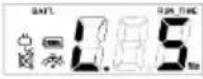 | The audible alarm will | continuously beep when the remaining runtime is less than the selected value. | |
| Self Test | Yes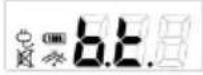 | 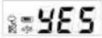 Escape to function menu Escape to function menu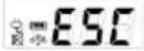 | No Action | In Line Mode, select YES to perform a Self Test on the battery. |
| Buzzer Setting | Buzzer on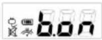 | 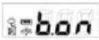 Buzzer off Buzzer off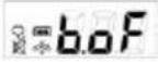 | Buzzer on | “b.on” is buzzer enabled; “b.of” is buzzer disabled.If b.of is selected, the unit will mute all alarms except for fault or overload condition. |
| LCD Sleep | Auto off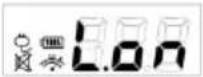 | 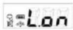 Always on Always on | L.on | “L.on” (Auto Off is on):In Line Mode, LCD screen will off automatically after 1 min of inactivity; in Battery Mode, LCD screen is always on.“L.oF” (Auto Off is off): LCD screen is always on. |
| Last Fault Reason | 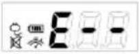 | There is no confirm | page for this item. It will only show the error code for last fault reason.E01 : Charger fault (Over Charge).E02 : Charger fault (No Charge)E11 : Battery FaultE21 : Output short.E22 : Over load. | |
| Back to Default | 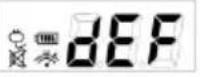 | No Action | Select Yes to restore the UPS factory default settings. | |
| Escape Item | 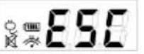 | Return to the previous | page. | |
For more information, visit eu.cyberpowersystems.com or contact
CyberPower Systems B.V.
Flight Forum 3545 5657DW Eindhoven The Netherlands
Tel: +31 40 2348170, E-MAIL: sales@cyberpower-
eu.com CyberPower Systems Inc. (USA)
4241 12th Avenue East, Suite 400, Shakopee, MN 55379, U.S.A.
Tel: +1 952 4039500, Fax: +1 952 4030009, E-MAIL: sales@cyberpowersystems.com
Entire contents copyright ©2004 CyberPower Systems B.V., All rights reserved.
Reproduction in whole or in part without permission is prohibited. PowerPanel® and
PowerPanel® Plus are trademarks of CyberPower Systems (USA) Inc.





FR
natural_image
Isometric line drawing of a rectangular electronic device with ventilation grilles and a central hub (no text or symbols)OR1000ERM1U/OR1500ERM1U Manuel d'utilisation
K01-0000841-00
INSTRUCTIONS IMPORTANTES RELATIVES À LA SÉCURITÉ
(CONSERVEZ CES INSTRUCTIONS)
1. Ecran numérique
natural_image
Diagram of a rectangular electronic device with a separate slot and an arrow indicating rotation (no text or symbols)natural_image
Isometric line drawing of a rectangular electronic device with a flat top and internal components, showing no text or symbols.natural_image
Diagram of a rectangular electronic device with an inset showing internal components (no text or symbols)natural_image
Isometric line drawing of a rectangular electronic device with internal components (no text or symbols)natural_image
Isometric line drawing of a rectangular electronic device with internal components and mounting holes (no text or symbols)Flight Forum 3545, 5657DW Eindhoven, The Netherlands
TEL: +31 (0)40 2348170, FAX: +31 (0)40 2340314, E-MAIL: sales@cyberpower-eu.com
CyberPower Systems Inc. (USA) 4241 12th Avenue East Suite 400 Shakopee, MN 55379, U.S.A.
Tél: +1 952 4039500, Fax: +1 952 4030009, E-MAIL: sales@cyberpowersystems.com
natural_image
Isometric line drawing of a rectangular electronic device with ventilation grilles and mounting holes (no text or symbols)ACHTUNG! The UPS must be connected to a grounded AC power outlet with fuse or circuit breaker protection. DO NOT plug the UPS into an outlet that is not grounded. If you need to de-energize this equipment, turn off and unplug the UPS.
INSTALLATION IHRER USV
AUSPACKEN
Watts (W) x 1.67 = VA or Amps (A) x 230 = VA
BESCHREIBUNG
1. LCD-Anzeige
BATTERY REPLACEMENT PROCEDURE:
natural_image
Isometric line drawing of a rectangular electronic device with a separate slot and arrow indicating rotation (no text or symbols)natural_image
Isometric line drawing of a computer drive chassis with labeled ports and connectors (no text or symbols)natural_image
Isometric line drawing of a rectangular electronic device with a close-up inset showing internal components (no text or symbols)natural_image
Isometric line drawing of a rectangular electronic device with internal components and mounting holes (no text or symbols)natural_image
Isometric line drawing of a rectangular electronic device with internal components and mounting holes (no text or symbols)Netherlands Tel: +31 40 2348170, E-MAIL:
sales@cyberpower-eu.com
CyberPower Systems Inc. (USA) 4241 12th Avenue East, Suite 400, Shakopee, MN 55379, U.S.A.
Tel: +1 952 4039500, Fax: +1 952 4030009, E-MAIL: sales@cyberpowersystems.com
natural_image
Isometric line drawing of a rectangular electronic device with ventilation slots and a central hub (no text or symbols)OR1000ERM1U/OR1500ERM1U
Manual del usuario
K01-0000841-00
natural_image
Diagram of an open DVD drive with a separate slot and cable, showing no text or symbols.natural_image
Isometric line drawing of a computer drive chassis with labeled ports and connectors (no text or symbols)natural_image
Diagram of a computer drive showing internal components and an inset close-up view (no text or labels)natural_image
Isometric line drawing of a rectangular electronic device with ports and connectors (no text or symbols)natural_image
Isometric line drawing of a rectangular electronic device with internal components and mounting holes (no text or symbols)natural_image
Isometric line drawing of a rectangular electronic device with ventilation grilles and ports (no text or symbols)1. LCD displej
natural_image
Diagram of a rectangular electronic device with a flat top and a separate slot, showing internal components (no text or symbols)natural_image
Isometric line drawing of a rectangular electronic device with a base and internal components, showing no text or symbols.natural_image
Diagram of an open DVD drive showing internal components and a close-up inset (no text or labels)natural_image
Isometric line drawing of a rectangular electronic device with a flat top and internal ports (no text or symbols)natural_image
Isometric line drawing of a rectangular electronic device with internal components (no text or symbols)natural_image
Isometric line drawing of a rectangular electronic device with ventilation grilles and mounting holes (no text or symbols)1. Wyświetlacz LCD
natural_image
Isometric line drawing of a rectangular electronic device with a separate slot and two additional slots (no text or symbols)natural_image
Isometric line drawing of a rectangular electronic device with internal components and mounting brackets (no text or symbols)natural_image
Diagram of an open drive chassis with a magnified inset showing internal components (no text or labels)natural_image
Isometric line drawing of a rectangular electronic device with a central internal component and mounting holes (no text or symbols)natural_image
Isometric line drawing of a rectangular electronic device with internal components and mounting holes (no text or symbols)LCD FUNCTION SETUP GUIDE
natural_image
Isometric line drawing of a rectangular electronic device with ventilation grilles and ports (no text or symbols)Watts (W) x 1.67 = VA or Amps (A) x 230 = VA
DESCRIERE
1. DISPLAY-ul LCD
LCD-ul arata informatii legate de UPS cu icoane si mesaje.
9. Serial Port catre computerul personal
natural_image
Isometric line drawing of a rectangular electronic device with a separate slot and arrow indicating motion (no text or symbols)natural_image
Isometric line drawing of a rectangular electronic device with internal components and mounting points (no text or symbols)natural_image
Diagram of a computer drive with an inset showing internal components (no text or labels)- Deconectati cablul rosu si negru.
natural_image
Isometric line drawing of a rectangular electronic device with internal components (no text or symbols)- Indepartati surubul ce tine conectorul de cablu.
natural_image
Isometric line drawing of a rectangular electronic device with internal components and directional arrows indicating movement (no text or symbols)Netherlands Tel: +31 40 2348170, E-MAIL:
sales@cyberpower-eu.com
CyberPower Systems Inc. (USA) 4241 12th Avenue East Suite 400 Shakopee, MN 55379, U.S.A.
Tel: +1 952 4039500, Fax: +1 952 4030009, E-MAIL: sales@cyberpowersystems.com
natural_image
Isometric line drawing of a rectangular electronic device with ventilation grilles and mounting holes (no text or symbols)ОПИСАНИЕ
1. ЖК-дисплей
natural_image
Diagram of an open DVD drive with a flat top and a separate slot, shown in isometric view (no text or symbols)natural_image
Isometric line drawing of a rectangular electronic device with internal components and mounting holes (no text or symbols)natural_image
Diagram of a rectangular electronic device with a close-up inset showing internal components (no text or symbols)natural_image
Isometric line drawing of a rectangular electronic device with ports and an internal slot (no text or symbols)natural_image
Isometric line drawing of a rectangular electronic device with internal components and mounting holes (no text or symbols)- IMPORTANT SAFETY INSTRUCTIONS
- INSTALLING YOUR UPS SYSTEM
- UNPACKING
- OVERVIEW
- HOW TO DETERMINE THE POWER REQUIREMENTS OF YOUR EQUIPMENT
- DESCRIPTION
- LCD module display
- Power on LED
- Power Switch
- LCD function selected switch
- Battery, Surge and AVR Outlets
- Surge Outlets
- Expansion Port
- Communication Protection Ports
- USB Port to PC
- Serial Port to PC
- Circuit Breaker
- AC Input
- Hardware Installation Guide
- BATTERY REPLACEMENT
- BATTERY REPLACEMENT PROCEDURE:
- TROUBLE SHOOTING
- CYBERPOWER GREENPOWER UPS™ TECHNOLOGY
- Advanced Energy-Saving Patented Bypass Technology
- TECHNICAL SPECIFICATIONS
- FUNCTION SETUP GUIDE
- CyberPower Systems B.V.
- OR1000ERM1U/OR1500ERM1U Manuel d'utilisation
- INSTRUCTIONS IMPORTANTES RELATIVES À LA SÉCURITÉ
- (CONSERVEZ CES INSTRUCTIONS)
- Ecran numérique
- INSTALLATION IHRER USV
- AUSPACKEN
- BESCHREIBUNG
- LCD-Anzeige
- OR1000ERM1U/OR1500ERM1U
- Manual del usuario
- LCD displej
- Wyświetlacz LCD
- LCD FUNCTION SETUP GUIDE
- DESCRIERE
- DISPLAY-ul LCD
- Serial Port catre computerul personal
- ОПИСАНИЕ
- ЖК-дисплей
Brand : CyberPower
Model : OR1000ERM1U
Category : Uninterruptible power supply