
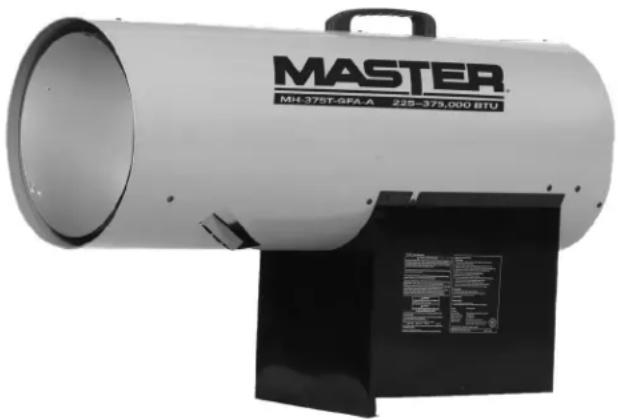
MH-375T-GFA - Heating Master - Free user manual and instructions
Find the device manual for free MH-375T-GFA Master in PDF.

| Product type | Propane forced air heater |
| Usage | Temporary construction site heating (outdoor or well-ventilated indoor) |
| Brand | Master |
| Model | MH-375T-GFA |
| Energy source | Propane (LPG) + 120 V / 60 Hz |
| Heat output | 225,000 - 375,000 BTU/h |
| Fuel consumption | 17.4 kg/h |
| Autonomy | 11.5 hours (with 45 kg cylinder) |
| Maximum heated area | 864 m² |
| Airflow | 42 m³/min |
| Maximum outlet temperature | 646 °C |
| Required propane cylinder | 45 kg |
| Manifold pressure | 7-10 PSI |
| Power supply | 120 V / 60 Hz, 1.24 A |
| Safety | Thermal cutoff, tip-over switch, leak protection |
| Maintenance | Monthly internal cleaning, leak check before use |
| Spare parts | Handle, thermal cutoff, spark plug, sensor, motor, regulator/hose, etc. |
| Repairability | Repair by qualified personnel, parts list provided |
| Warranty | 1 year limited |
Frequently Asked Questions - MH-375T-GFA Master
User questions about MH-375T-GFA Master
0 question about this device. Answer the ones you know or ask your own.
Ask a new question about this device
Download the instructions for your Heating in PDF format for free! Find your manual MH-375T-GFA - Master and take your electronic device back in hand. On this page are published all the documents necessary for the use of your device. MH-375T-GFA by Master.
USER MANUAL MH-375T-GFA Master
natural_image
Exterior view of a master industrial exhaust gun (no signage or text on body)
FACTORY ID: 500
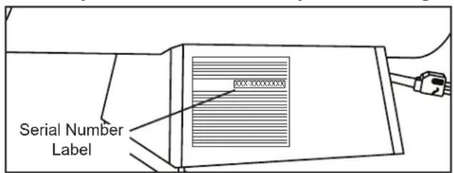
Locating Your Serial Number:
Your serial number can be found on a white label on the right side cover of your heater. It will begin with the letters "G" followed by 9 digits. For Example: G181200001. Have your Serial Number ready before calling customer service at 800-641-6996.
▲DANGER GENERAL HAZARD WARNING:
FAILURE TO COMPLY WITH THE PRECAUTIONS AND INSTRUCTIONS PROVIDED WITH THIS HEATER, CAN RESULT IN DEATH, SERIOUS BODILY INJURY AND PROPERTY LOSS OR DAMAGE FROM HAZARDS OF FIRE, EXPLOSION, BURN. ASPHYXIATION, CARBON MONOXIDE POISONING AND / OR ELECTRIC SHOCK.
ONLY PERSONS WHO CAN UNDERSTAND AND FOLLOW THE INSTRUCTIONS SHOULD USE OR SERVICE THIS HEATER. IF YOU NEED ASSISTANCE OR HEATER INFORMATION SUCH AS AN INSTRUCTIONS MANUAL, LABEL, ETC. CONTACT THE MANUFACTURER.
WARNING
FIRE, BURN, INHALATION, AND EXPLOSION HAZARD. KEEP SOLID COMBUSTIBLES, SUCH AS BUILDING MATERIALS, PAPER OR CARDBOARD, A SAFE DISTANCE AWAY
FROM THE HEATER AS RECOMMENDED BY THESE INSTRUCTIONS. NEVER USE THE HEATER IN SPACES WHICH DO OR MAY CONTAIN VOLATILE OR AIRBORNE COMBUSTIBLES, OR PRODUCTS SUCH AS GASOLINE, SOLVENTS, PAINT THINNERS, DUST PARTICLES OR UNKNOWN CHEMICALS.
TABLE OF CONTENTS
Safety Information....2-5
Unpacking....5
Specifications....6
Features......6
What's in the Box....6
Assembly....7
Operation....7-9
Ventilation....10
Storage/Maintenance....10
Wiring Diagram....11
Troubleshooting Guide....12
Exploded View....13
Parts List....14
Limited Warranty....15
SAFETY INFORMATION
▲WARNING NOT FOR HOME OR RECREATIONAL VEHICLE USE.
DANGER
Carbon Monoxide Hazard This heater produces carbon monoxide, which has no odor. Burning the heater in an enclosed space can kill you. Never use the heater in
enclosed spaces such as a tent, a camper, any vehicle or recreational vehicle (RV), enclosed shelter, or any other enclosed areas.
DANGER
If the information in this manual is not followed exactly, a fire or explosion may result causing property damage, personal injury or loss of life.
DANGER
Not for use in residential living areas or in non-adequately ventilated enclosed spaces. Never bring or store a propane cylinder indoors.
▲ WARNING
DO NOT OPERATE THIS HEATER UNTIL YOU HAVE READ AND THOROUGHLY UNDERSTAND THESE SAFETY AND OPERATING INSTRUCTIONS.
Failure to comply with the precautions and instructions provided with this heater can result in death, serious bodily injury, property loss or damage from the hazards of fire, explosions, burns, asphyxiation or carbon monoxide poisoning. Only persons who can read and understand these instructions should use or service this heater.
▲WARNING
This is an unvented portable heater. It uses air (oxygen) from the area in which it is used. Adequate combustion and ventilation air must be provided. Refer to VENTILATION on Page 10.

WARNING: This product can expose you to chemicals, including lead, which is known to the State of California to cause cancer and birth defects or other reproductive harm. For more information go to www.P65Warnings.ca.gov.
This heater is designed and approved for use as a construction heater in accordance with the standard for Gas-Fired Construction Heaters ANS Z83.7 * CSA 2.14-2017. CHECK WITH YOUR LOCAL FIRE SAFETY AUTHORITY IF YOU HAVE ANY QUESTIONS ABOUT APPLICATIONS. Other standards govern the use of fuel gasses and heating products for specific uses. Your local authority can advise you about these.
SAFETY INFORMATION (CONT.)
▲WARNING
RISK OF INDOOR AIR POLLUTION!
The products described in this manual are propane direct-fired, forced air heaters. Propane forced air heaters are primarily intended for use for temporary heating of buildings under construction, alteration or repair. Direct-fired means that all of the combustion products of the heater enter the heated space. This appliance is rated at 98% combustion efficiency, but does produce small amounts of carbon monoxide.
Carbon monoxide is toxic. Humans can tolerate only small amounts of carbon monoxide and so precautions
DANGER
CARBON MONOXIDE POISONING MAY LEAD TO DEATH!
should be taken to provide proper ventilation. Failure to provide proper ventilation in accordance with the instructions in this manual can result in death.
People with breathing problems should consult a physician before using this heater.
Early signs of carbon monoxide poisoning resemble the flu. Symptoms of improper ventilation / carbon monoxide poisoning are:
Headache · Dizziness · Nausea · Dry Mouth Sore Throat · Burning of Nose and Eyes
If you experience any of these symptoms:
GET FRESH AIR AT ONCE! Have your heater serviced and check for proper ventilation. Some people are more affected by carbon monoxide than others. These include: pregnant women, those with heart or lung problems, anemia or those under the influence of alcohol or at high altitudes.
FOR OUTDOOR USE. INDOOR USE PERMITTED ONLY
FOR: The temporary heating of adequately ventilated buildings or structures under construction, alteration or repair! Provide at least a three square foot (2,800 sq cm) opening of outside air for every 100,000 Btu / Hr heater rating. Refer to “Ventilation” on page 9 for further instructions.
DANGER
- DO NOT attempt to light the heater.
– Extinguish any open flame. - Shut off gas to heater.
- If odor continues, contact your local gas supplier or fire department.
- DO NOT touch or use any electric switch or any electric device that can cause a spark.
– Immediately call your gas supplier from a neighbors phone. Follow the gas suppliers instructions. - If you can not reach your gas supplier, call the fire department.
– Service must be done by a qualified service agency.
NEVER store or use gasoline or other flammable vapors and liquids in the vicinity of this heater.
NEVER store a propane (LP) cylinder not connected to this heater in the vicinity of this heater.
▲WARNING
RISK OF BURNS, FIRE AND EXPLOSION!
NEVER connect heater to an unregulated gas supply.
NEVER obstruct the flow of combustion and ventilation air. (The front and rear of heater).
NEVER use duct work in front or rear of heater.
NEVER modify this heater or operate a heater that has been modified.
NEVER service, move or handle heater while still hot or operating
Keep all combustible materials away from this heater.
The appliance are be kept clear and free from combustible materials, gasoline and other flammable vapors and liquid.
ALWAYS use the electrical power (voltage and frequency) specified on the model plate of the heater.
ALWAYS use only 14 AWG or better extension cord.
ALWAYS unplug the heater when not in use.
| Minimum Clearance From Combustibles | |||
| Sides Top | Front Rear | ||
| 24 in. 72 | in. 120 in. 24 | in. | |
▲ WARNING
KEEP CHILDREN, ANIMALS, CLOTHING AND COMBUSTIBLES AWAY FROM HEATER.
SAFETY INFORMATION (CONT.)
▲WARNING AIR QUALITY HAZARD
- Do not use this heater for heating human living quarters
- Use of direct-fired heaters in the construction environment can result in exposure to levels of CO, CO2 , and NO2 considered to be hazardous to health and potentially life threatening
– Do not use in unventilated areas
- Know the signs of CO and CO_2 poisoning
• Headaches, stinging eyes
• Dizziness, disorientation
- Difficulty breathing, feels of being suffocated
– Proper ventilation air exchange (OSHA 29 CFR 1926.57) to support combustions and maintain acceptable air quality shall be provided in accordance with OSHA 29 CFR Part 1926.154, ANSI A10.10 Safety Requirements for Temporary and Portable Space Heating Devices and Equipment used in the Construction Industry or the Natural Gas and Propane Installation Codes CSA B149.1
- Periodically monitor levels of CO, CO_2 and NO_2 existing at the construction site – at the minimum at the start of the shift and after 4 hours.
- Provide ventilation air exchange, either natural or mechanical, as required to maintain acceptable indoor air quality
- Ensure that the flow of combustion and ventilation air exchanges cannot become obstructed
- As the building “tightens up” during the construction phase ventilation may need to be increased
USA 8-Hr Time weighted average (OSHA 29 CFR 1926.55 App A)
CO 50 ppm 25 ppm
CO_2 5000 ppm 5000 ppm
NO₂ 3 ppm (Reg 833)
USA – Ceiling Limit (Short Term Exposure Limit = 15 minutes)
CO 100 ppm
CO_2
NO_2 5 ppm
Canada 8-hr time weighted average WorkSafe BC OHS Guidelines Part 5.1 and Ontario Workplaces Reg 833
Canada STEL (15 minutes Reg 833/1 hour WSBC) WorkSafe BC OHS Guidelines Part 5.1 and Ontario Workplaces Reg 833
15000 ppm (WSBC) 30000 ppm (Reg 833) 1.0 ppm (WorkSafeBC) 5.0 ppm (Reg 833)
SAFETY INFORMATION (CONT.)
▲WARNING RISK OF ELECTRIC SHOCK!
⚠ WARNING Electrical Grounding Instructions: This appliance is equipped with a three-prong (grounding) plug for your protection against shock hazard and should be plugged directly into a properly grounded three-prong receptacle.
⚠ WARNING For use with propane (LP) gas only.
ALWAYS install the heater so that it is not directly exposed to water spray, rain, dripping water, or wind.
- Use heater in accordance with all local codes. In the absence of local codes, refer to The National Fuel Code, ANSI Z223.1.
- This heater is shipped from the factory for use with propane (LP) gas only. Do not convert to any other gas. Installation must conform to local codes, or in their absence, with the standard for the Storage and Handling of Liquefied Petroleum Gases ANSI/NFPA 58 and the Natural Gas and Propane Installation Code CSA B149.1.
- Gas supply connections should be checked by using a 50/50 soap and water solution. Never use a flame to check for gas leaks.
-
Locate LP cylinder at least 6 feet (10 ft. in Canada) from the heater, and do not direct heater discharge towards the LP cylinder unless it is at least 20 feet from the heater.
-
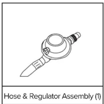
Use only the regulator and hose assembly provided with this heater. Inspect the regulator/hose assembly prior to each use of the heater. If there is excessive abrasion or wear, or if the hose is cut, replace it with the proper assembly shown in the parts list, prior to using the heater.
- The hose assembly shall be visually inspected prior to each use of the heater. If it is evident there is excessive abrasion or wear, or the hose is cut, it shall be replaced prior to the heater being put into operation. The replacement hose assembly shall be that specified by the manufacturer.
| Manifold, Minimum, and Maximum Supply Pressure | |
| MH-375T-GFA-A | |
| Man. 7–10 PSI | |
| Min. 23 PSI | |
| Max. Bottle Pressure | |
WARNING
The hose assembly shall be pro tected from traffic,
building material and contact with hot surfaces both during use and while in storage.
WARNING
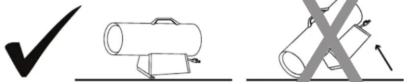
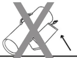
RISK OF FIRE! DO NOT POSITION HEATER IN A DOWNWARD ANGLE. ALWAYS LOCATE HEATER ON A STABLE AND LEVEL SURFACE (SEE FIGURE 1)!
Figure 1
natural_image
Diagram showing two cylindrical objects with a crossed X-shaped line and an upward arrow, no text or symbols present.UNPACKING
- Remove all packing items applied to heater for shipment. Keep plastic cover caps attached to inlet connector and hose / regulator assembly for storage.
-
Remove all items from carton
-
Check all items for shipping damage. If the heater is damaged, promptly inform dealer where you purchased the heater.
CAUTION
The Propane (LP) gas pressure regulator and hose assembly
supplied with the heater must be used without alteration.
SPECIFICATIONS
| Model # MH-375T-GFA-A | |
| BTU 225-375,000 | |
| Fuel Consumption (Lbs./hr) 10.4 / 17.4 | |
| Maximum Operating Hours 11.5 | |
| Required Cylinder Lbs. 100 | |
| Fuel Type Propane | |
| Heating Area (Ft.2) 9300 | |
| Air Flow (CFM) 1500 | |
| Max Outlet Temp (°F) 1195 | |
| Volts: AC/Hz 120V / 60Hz | |
| Amps 1.24 A | |
Specifications subject to change without notice.
FEATURES
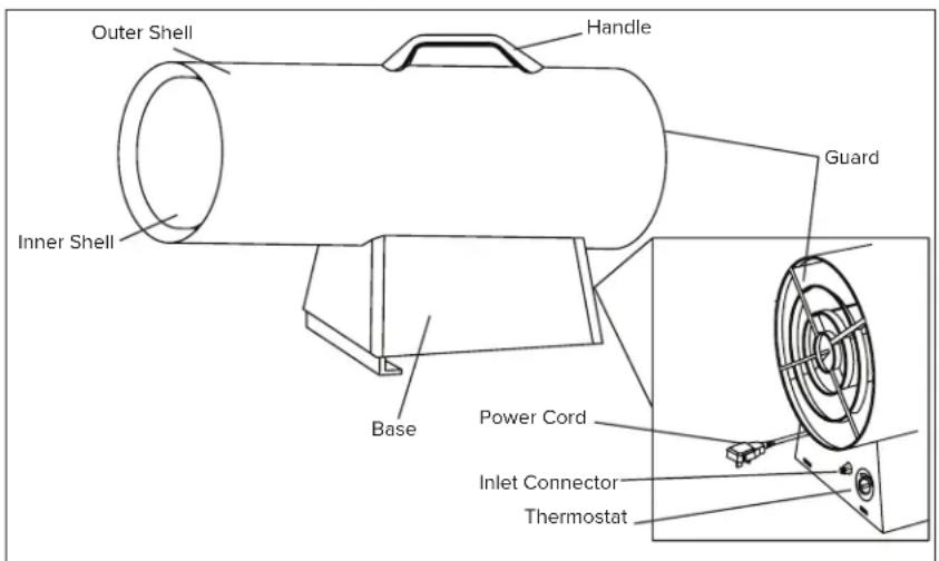
WHAT'S IN THE BOX
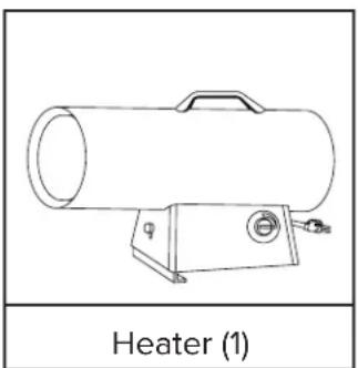
natural_image
Line drawing of a portable heater with labeled component (1), no text or symbols on the diagram itselfTools Needed:
- Phillips Head Screw Driver
ASSEMBLY
- Attach the handle to the heater using the provided screws.
OPERATION
Propane Supply / Information:
Propane (LP)
This heater is not supplied with a propane cylinder. Use only an approved propane cylinder.
LP Characteristics
- Flammable, explosive under pressure, heavier than air and pools in low areas.
– In its natural state, propane has no odor, but for your safety an odor that smells like rotten eggs has been added. - Contact of propane (LP) gas with the skin can cause freeze burns.
– Heater is manufactured for use with propane gas only. DO NOT attempt to convert to any other gas. Such modifications are dangerous and will void the warranty. - When heater is not in use, LP Cylinder must be turned OFF.
- Be sure that the LP Cylinder is located on a level and stable surface.
- DO NOT use this heater in a basement or below ground level. Propane is heavier than air and will always seek the lowest level. If you suspect a leak, shut off the valve at the LP Cylinder immediately.
The Propane (LP) cylinder must also be equipped with the following
– A collar to protect the gas valve.
- A shut-off valve terminating a LP cylinder valve outlet as specified in the American National Standard for Compressed Gas Cylinder Valve Outlets and Inlets Connections.
- A safety relief valve having direct communications with the vapor space of the LP cylinder.
- The heater must operate on vapor withdrawal from the operating cylinder.
The amount of Propane (LP) used with this heater varies. Both factors are
– The amount of gas in the cylinder of LP.
- The temperature of the LP tank and its surroundings.
| Minimum Number of LP Cylinders | |
| Average Temp(°F) | MH-375T-GFA-A100 lb. Cylinder |
| 40° 2 | |
| 32° | Use Larger Tank |
| 20° | |
| 10° | |
| 0° | |
| -10° | |
| -20° | |
The table above shows the minimum number of 100 lb. LP cylinders required in cold weather. Your local LP dealer will help you select the proper LP supply system.
CAUTION
Propane is safe to use when properly handled. Careless
handling of the LP cylinder could result in a fire and or an explosion.
– Always keep LP cylinder fastened and upright.
- Avoid tipping the LP cylinder on its side when connected to a regulator, since this may cause damage to diaphragm in the regulator.
- Handle valves with care.
- Never connect an unregulated LP cylinder to a construction heater.
- DO NOT subject LP cylinder to excessive heat.
- Tightly close the gas shutoff valve on the LP cylinder after each use.
- All fittings must be protected when disconnected from the LP cylinder.
- Never store an LP cylinder inside a building or in the vicinity of an gas burning appliances.
▲ CAUTION
The disconnected tank must never be stored in a building,
garage or any other enclosed area.
Installation of this appliance at altitudes above 2000 ft (610 m) shall be in accordance with local codes, or in the absence of local codes, the National Fuel Gas Code, ANSI Z223.1/NFPA 54, or National Standard of Canada, Natural Gas and Propane Installation Code, CSA B149.1.
OPERATION (CONT.)
CAUTION
The disconnected tank must never be stored in a
building, garage or any other enclosed area.
WARNING
Purging and filling of the LP cylinders must be
performed by personnel who have been thoroughly trained in accepted LP gas industry procedures. Failure to follow these instructions may result in explosion, fire, severe personal injury or death.
Pre-Lighting Instructions:
Connecting the LP Cylinder
ALL NEW LP CYLINDERS MUST BE PURGED BEFORE THE FIRST FILLING.
– Turn heater gas valve knob and LP cylinder valve to OFF position.
- LP cylinder valve equipped with old style fitting has LEFT HANDED THREADS. Turn fitting CLOCKWISE to loosen. Protect this fitting when disconnected from LP cylinder.
- Have your LP cylinder filled by your local propane gas supplier.
- Some LP cylinders have a bleed-OFF valve. This valve should be inspected for leaks after each filling of the LP cylinder. Turn the valve clockwise to close.
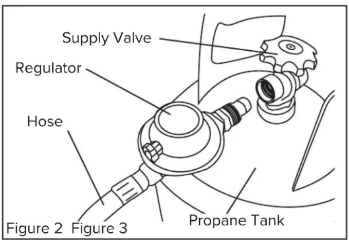
- Fasten full propane tank and connect proper fitting to LP cylinder valve by turning COUNTER-CLOCKWISE (see Figures 2 & 3).
- With heater gas valve knob still in OFF position turn ON the LP cylinder valve and check for leaks with soap solution.
Checking For Leaks
- To check for leaks, make up a 50/50 solution of dish soap and water. Apply this solution to all gas connections. If bubbles appear, there is a leak. If a leak is found, turn off the gas supply, and re-connect the leaking connection. If the leak persists after several tries, contact Pinnacle Customer Service at 800-641-6996.
- The installation of this heater must meet all local codes and/or gas utility requirements. In the absence of local codes, the National Fuel Code ANSI Z223.1 should be followed.
- The minimum clearances to any combustible construction materials must be maintained at all times (See Page 3).
- Inspect the heater before each use, and at least annually by a qualified service person.
OPERATION (CONT.)
Lighting Instructions:
Starting the Heater (Ignition)
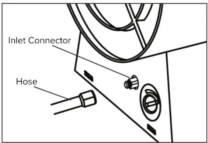
- Connect the heater to a three prong (grounded) power source. You must use a three prong (grounded) extension cord that is at least 6 feet long is a minimum of 14 AWG rating.
- Connect heater to a proper LP cylinder.
- Wait five (5) minutes for any glass to clear. Smell for gas, if you do not smell gas, go to step 5.
- Adjust the regulator setting to between 7 PSIG and 10 PSIG.
- Select desired heat setting with thermostat knob (see Figure 4).
CAUTION
Do not adjust the regulator above 10 PSIG or below 7
PSIG or the heater may not operate properly.
-
Turn power switch to the ON position. Heater will start within 20 seconds. (Figure 5)
-
If the heater does not start, the thermostat setting may be too low. Turn thermostat to higher setting to start heater.
NOTE: If the heater still does not start, turn power switch to OFF position and wait 10 seconds for safety control to reset. Then follow all starting procedures to light heater.
Shutdown Instructions
To Shut Off the Heater:
- Turn power switch to the OFF position
- Turn gas supply OFF by turning the LP cylinder valve CLOCKWISE to close.
- Disconnect heater from power supply.
Test Firing the Heater
Test fire your construction heater following the lighting instructions applicable to the gas control system employed.
Leak test all gas connections with 50/50 soap and water solution prior to start-up. Soap bubbles indicate a gas leak. DO NOT use a match or flame to test for gas leaks.
NOTE: Heater surface temperature must be cold before initiating service, cleaning or storage.
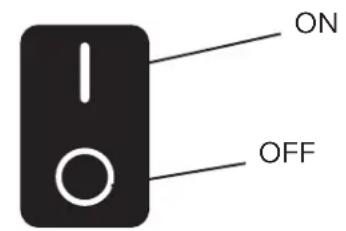
Power Switch
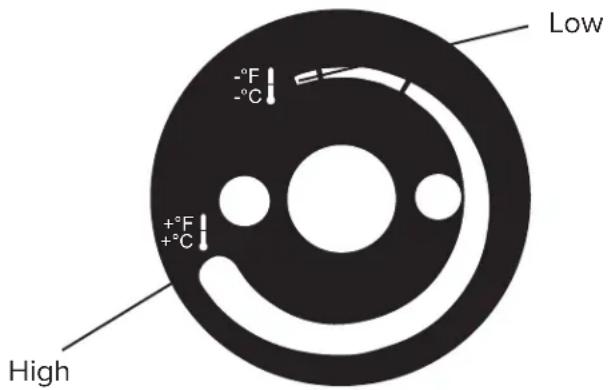
Thermostat Knob
Figure 5
VENTILATION
▲ DANGER CARBON MONOXIDE POISONING MAY LEAD TO DEATH!
– Risk of indoor air pollution and Carbon Monoxide Poisoning. Use heater only in well ventilated areas.
– Refer to Safety Information on pages 2-4 for information about Carbon Monoxide Poisoning.
Minimum Ventilation Opening Needed
| MH-375T-GFA-A |
| 11.25 ft. ^2 |
| 10,452 cm ^2 |
DANGER
Not for use in residential living areas or in non-adequately
ventilated enclosed spaces.
Always disconnect the heater from the LP cylinder before putting the heater into storage. If for any reason the heater is to be stored indoors, the tank MUST be disconnected from the LP cylinder, and the cylinder stored outdoors in a well-ventilated area, out of the reach of children, and in accordance with the Standard for Storage and Handling of Petroleum Gases, ANSI/NFPA 58 - latest edition and Natural Gas and Propane Installation Code, CSA B149.1. The plastic valve plug or valve cover supplied with the cylinder must be re-installed on the valve to protect the fitting from damage.
DANGER
Never store an LP cylinder inside of a building or near any
other gas or oil burning appliances.
NOTE: Installation and repair of this heater should be done by a qualified service person.
ALWAYS be sure to follow proper maintenance procedures. This should include cleaning the inside of the heater once a month and checking the spark gap at least once a heating season. Re-gap the terminals to 0.160" (4mm).
WIRING DIAGRAM
MH-375T-GFA-A
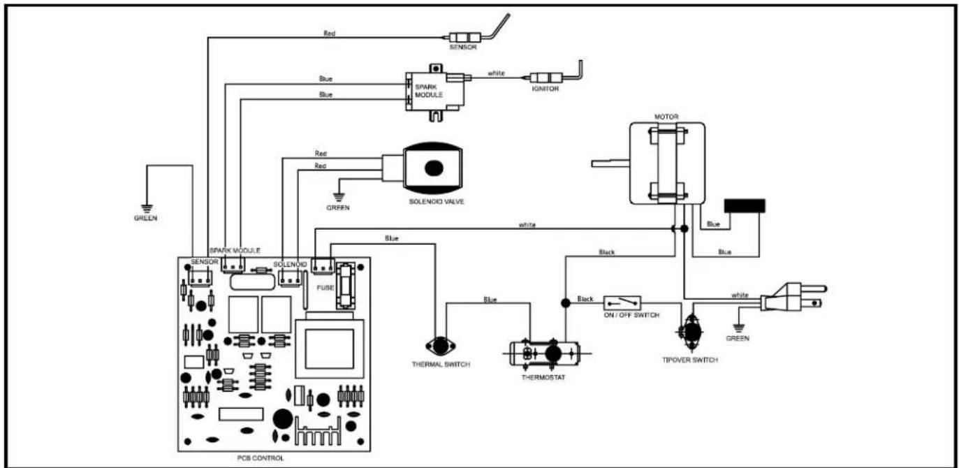
flowchart
graph TD
    A["GREEN"] --> B["SENSOR"]
    B --> C["SPARK MODULE"]
    C --> D["IGNITOR"]
    D --> E["MOTOR"]
    E --> F["Blue"]
    E --> G["Blue"]
    E --> H["Blue"]
    E --> I["Blue"]
    E --> J["Blue"]
    E --> K["Blue"]
    E --> L["Blue"]
    E --> M["Blue"]
    E --> N["Blue"]
    E --> O["Blue"]
    E --> P["Blue"]
    E --> Q["Blue"]
    E --> R["Blue"]
    E --> S["Blue"]
    E --> T["Blue"]
    E --> U["THERMAL SWITCH"]
    E --> V["THERMOSTAT"]
    E --> W["ON/OFF SWITCH"]
    E --> X["TIPOVER SWITCH"]
    E --> Y["GREEN"]
flowchart
graph TD
    A["POWER CORD"] --> B["AC/DC"]
    B --> C["MOTOR"]
    C --> D["CAPACITOR"]
    D --> E["ICU"]
    E --> F["AC"]
    F --> G["ICU"]
    G --> H["ICU"]
    H --> I["ICU"]
    I --> J["ICU"]
    J --> K["ICU"]
    K --> L["ICU"]
    L --> M["ICU"]
    M --> N["ICU"]
    N --> O["ICU"]
    O --> P["ICU"]
    P --> Q["ICU"]
    Q --> R["ICU"]
    R --> S["ICU"]
    S --> T["ICU"]
    T --> U["ICU"]
    U --> V["ICU"]
    V --> W["ICU"]
    W --> X["ICU"]
    X --> Y["ICU"]
    Y --> Z["ICU"]
    Z --> AA["ICU"]
    AA --> AB["ICU"]
    AB --> AC["ICU"]
    AC --> AD["ICU"]
    AD --> AE["ICU"]
    AE --> AF["ICU"]
    AF --> AG["ICU"]
    AG --> AH["ICU"]
    AH --> AI["ICU"]
    AI --> AJ["ICU"]
    AJ --> AK["ICU"]
    AK --> AL["ICU"]
    AL --> AM["ICU"]
    AM --> AN["ICU"]
    AN --> AO["ICU"]
    AO --> AP["ICU"]
    AP --> AQ["ICU"]
    AQ --> AR["ICU"]
    AR --> AS["ICU"]
    AS --> AT["ICU"]
    AT --> AU["ICU"]
    AU --> AV["ICU"]
    AV --> AW["ICU"]
    AW --> AX["ICU"]
    AX --> AY["ICU"]
    AY --> AZ["ICU"]
    AZ --> BA["ICU"]
    BA --> BB["ICU"]
    BB --> BC["ICU"]
    BC --> BD["ICU"]
    BD --> BE["ICU"]
    BE --> BF["ICU"]
    BF --> BG["ICU"]
    BG --> BH["ICU"]
    BH --> BI["ICU"]
    BI --> BJ["ICU"]
    BJ --> BK["ICU"]
    BK --> BL["ICU"]
    BL --> BM["ICU"]
    BM --> BN["ICU"]
    BN --> BO["ICU"]
    BO --> BP["ICU"]
    BP --> BQ["ICU"]
    BQ --> BR["ICU"]
    BR --> BS["ICU"]
    BS --> BT["ICU"]
    BT --> BU["ICU"]
    BU --> BV["ICU"]
    BV --> BW["ICU"]
    BW --> BX["ICU"]
    BX --> BY["ICU"]
    BY --> BZ["ICU"]
    BZ --> CA["ICU"]
    CA --> CB["ICU"]
    CB --> CC["ICU"]
    CC --> CD["ICU"]
    CD --> CE["ICU"]
    CE --> CF["ICU"]
    CF --> CG["ICU"]
    CG --> CH["ICU"]
    CH --> CI["ICU"]
    CI --> CJ["ICU"]
    CJ --> CK["ICU"]
TROUBLESHOOTING GUIDE
Locating Your Serial Number:
Your serial number can be found on a white label on the right side cover of your heater. It will begin with the letters "G" followed by 9 digits. For Example: G181200001. Have your Serial Number ready before calling customer service at 800-641-6996.
| Problem Possible Cause(s) Solution | ||
| Fan does not turn when electricity is connected. | 1. No electric power to heater.2. Blades of fan in contact with heater housing.3. Fan blades bent.4. Fan motor defective. | 1. Check current at outlet. If voltage is correct, inspect extension and power cords for cuts, frays or breaks2. Check housing for damage. Be sure there are no dents in the housing obstructing the fan.3. Straighten all fan blades.4. Replace motor assembly. |
| Heater will not fire (ignite). | 1. No spark at module.2. Corroded electrode. | 1. Inspect module wire. Re-attach or tighten if loose. Inspect spark module and replace if necessary. Inspect all other electrical components.2. Replace spark plug (multi-bracket assembly). |
| Heater stops running by itself. | 1. Temperature inside heater is too high, causing thermal switch to shut down operation.2. Damaged control valve.3. Dust or Debris accumulated in heater. | 1. If the heater input or output is restricted, the inside temperature can become too hot. Keep the areas in front and behind heater clear of obstructions.2. Replace control valve.3. Clean inside of heater. |
EXPLODED VIEW
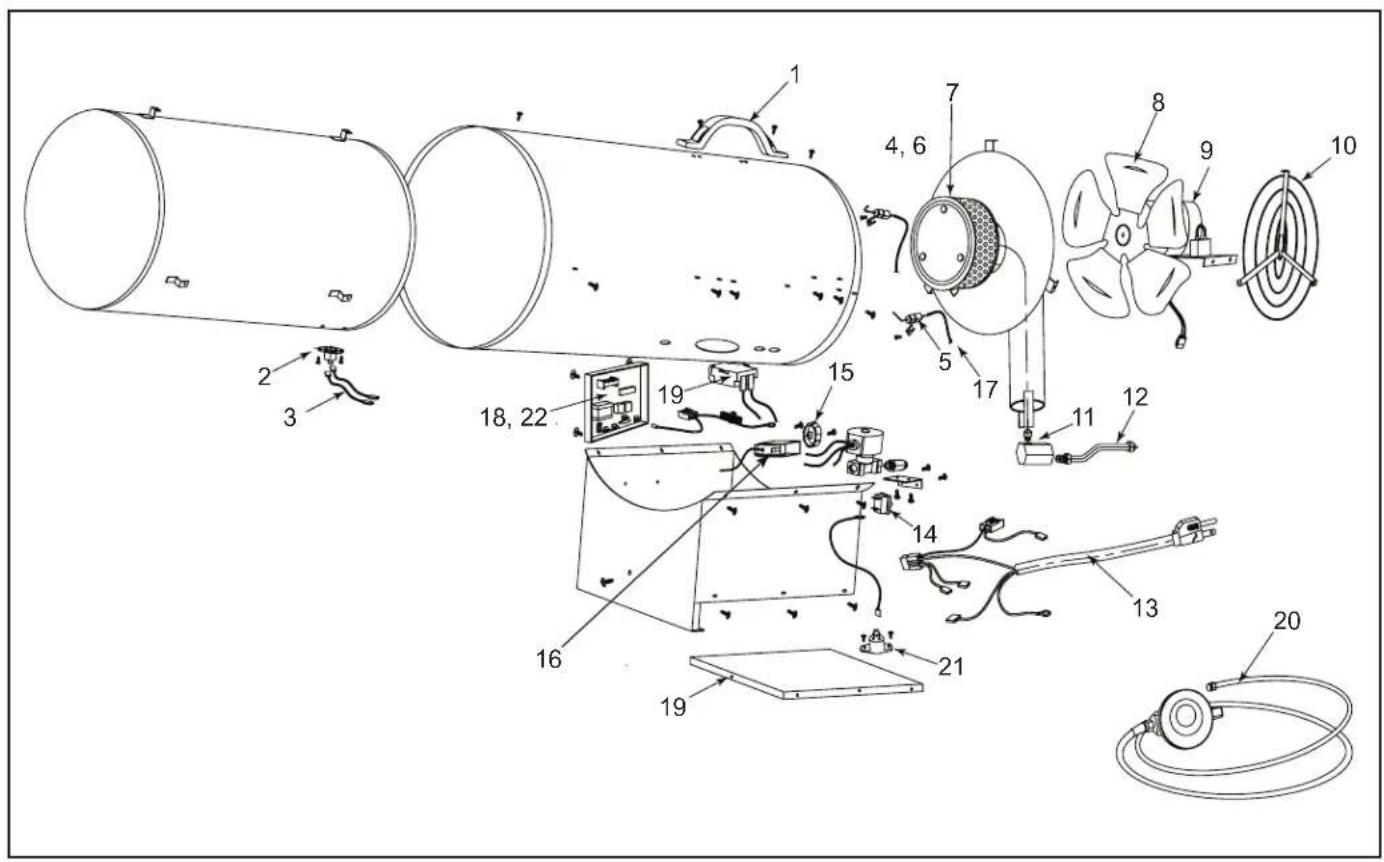
PARTS LIST
| Item # Description MH-375T-GFA-A | ||
| 1 Handle 70-001-0103 | ||
| 2 Thermal Switch 22-603-0003 | ||
| 3 Thermal Switch Cable 22-601-0006 | ||
| 4 Spark Plug 22-141-0002 | ||
| 5 Sensor Plug 22-141-0003 | ||
| 6 Spark Plug Bracket 22-504-0008 | ||
| 7 Burner Assembly 22-023-0005 | ||
| 8 Fan Assembly | 22-514-0003 | |
| 9 Motor Assembly | 22-061-0018 | |
| 10 | Guard | 22-101-0007 |
| 11 | Nozzle 22-081-0006 | |
| 12 | Tubing Assembly 22-605-0005 | |
| 13 | Power Cord Assembly 22-131-0003 | |
| 14 | Power Switch | 22-603-0004 |
| 15 | Thermostat Knob | 22-516-0003 |
| 16 | Thermostat | 22-012-0004 |
| 17 | Sensor Cable | 22-601-0007 |
| 18 | PCB | 22-521-0003 |
| 19 | Base Cover | 22-508-0005 |
| 20 | Regulator / Hose Assembly | 22-041-0003 |
| 21 | Tip Over Switch | 50-017-0001 |
| 22 | PCB Case | 22-506-0002 |
LIMITED WARRANTY
Pinnacle Climate Technologies, Inc. warrants this heater to the original retail purchaser only, to be free from defects in material and workmanship for a period of one (1) year from the date of initial purchase. This product must be properly installed, maintained and operated in accordance with the instructions provided.
Pinnacle Climate Technologies, Inc. requires reasonable proof of your date of purchase from an authorized retailer or distributor. Therefore, you should keep your sales slip, invoice or cancelled check from the original purchase. This Limited Warranty shall be limited to the repair or replacement of parts, which prove defective under normal use and service within the warranty period, and which Pinnacle Climate Technologies, Inc. shall determine at its reasonable discretion.
This warranty does not apply to products purchased for rental use.
This Limited Warranty does not cover any failures or operating difficulties due to normal wear and tear, accident, abuse, misuse, alteration, misapplication, improper installation or improper maintenance and service by you or any third party. Failure to perform normal and routine maintenance on the heater, shipping damage, damage related to insects, birds or animals of any kind, and damage due to weather conditions are also not covered. In addition, the Limited Warranty does not cover damage to the finish, such as scratches, dents, discoloration, rust or other weather damage, after purchase.
All transportation costs for the return of damaged product or parts will be the responsibility of the purchaser. Upon receipt of damaged item, Pinnacle Climate Technologies, Inc. will examine the item and determine if defective.
Pinnacle Climate Technologies, Inc. will repair or replace and return the item, freight pre-paid.
If Pinnacle Climate Technologies, Inc. finds the item to be in normal operating condition, or not defective the item will be returned freight collect. This Limited Warranty is in lieu of all other express warranties. Pinnacle Climate Technologies, Inc. disclaims all warranties for products that are purchased from sellers other than authorized dealers or distributors.
AFTER THE PERIOD OF THE ONE (1) YEAR EXPRESS WARRANTY EXPIRES, Pinnacle Climate Technologies, Inc. DISCLAIMS ANY AND ALL IMPLIED WARRANTIES, INCLUDING WITHOUT LIMITATION THE IMPLIED WARRANTIES OF MERCHANTABILITY AND FITNESS FOR A PARTICULAR APPLICATION. FURTHER, Pinnacle Climate Technologies, Inc. SHALL HAVE NO LIABILITY WHATSOEVER TO PURCHASER OR ANY THIRD PARTY FOR ANY SPECIAL, INDIRECT, PUNITIVE INCIDENTAL, OR CONSEQUENTIAL DAMAGES. Pinnacle Climate Technologies, Inc. assumes no responsibility for any defects caused by third parties. This Limited Warranty gives the purchaser specific legal rights; a purchaser may have other rights depending upon where he or she lives. Some states do not allow the exclusion or limitation of special, incidental or consequential damages, or limitations on how long a warranty lasts, so the above exclusion and limitations may not apply to you.
Pinnacle Climate Technologies, Inc. does not authorize any person or company to assume for it any other obligation or liability in connection with the sale, installation, use, removal, return or replacement of its equipment, and no such representations are binding on Pinnacle Climate Technologies, Inc.
Always be sure to specify the model number and serial number when making any claim with Pinnacle Climate Technologies, Inc. For your convenience, use the space provided below to list this information.
Locating Your Serial Number:
Your serial number can be found on a white label on the right side cover of your heater. It will begin with the letters "G" followed by 9 digits. For Example: G181200001. Have your Serial Number ready before calling cus-
tomer service at 800-641-6996.
Model #:
Serial #:
Date of Purchase: ____
NUMÉRO DE MODÈLE
MH-375T-GFA-A
NOTE AU CLIENT : LIRE ET CONSERVER CE MANUEL POUR CONSULTATION ULTÉRIEURE
natural_image
Exterior view of a master-type portable gas turbine with black base (no signage or text on body)
ID USINE : 500
1,0 ppm (WorkSafeBC)
5,0 ppm (règl. 833)
CONSIGNES DE SÉCURITÉ (SUITE)
▲ AVERTISSEMENT
RISQUE DE DÉCHARGE ÉLECTRIQUE!
▲ AVERTISSEMENT
natural_image
Simple line drawing of a cylindrical device with a checkmark and base, no text or symbols present.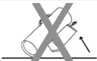
natural_image
Diagram showing two cylindrical objects crossed by a diagonal line, with an arrow indicating force or movement (no text or symbols)DÉBALLAGE
natural_image
Line drawing of a cylindrical industrial device labeled 'Chaufferette (1)' at the bottom, with no other text or symbols present.LISTE DES PIÈCES
natural_image
Exterior view of a master-type portable gas turbine with black base (no signage or text on body)

ID DE FÁBRICA: 500
1.0 ppm (WorkSafeBC)
5.0 ppm (Reg. 833)
natural_image
Two diagrams showing a cylindrical device with a checkmark and a cross-shaped object, both without any text or symbols.DESEMPAQUE
natural_image
Line drawing of a cylindrical device labeled 'Calentador (1)' at the bottom, with no other text or symbols present.LISTA DE PIEZAS
- Locating Your Serial Number:
- ▲DANGER GENERAL HAZARD WARNING:
- WARNING
- TABLE OF CONTENTS
- SAFETY INFORMATION
- ▲WARNING NOT FOR HOME OR RECREATIONAL VEHICLE USE.
- DANGER
- ▲ WARNING
- DO NOT OPERATE THIS HEATER UNTIL YOU HAVE READ AND THOROUGHLY UNDERSTAND THESE SAFETY AND OPERATING INSTRUCTIONS.
- ▲WARNING
- SAFETY INFORMATION (CONT.)
- RISK OF INDOOR AIR POLLUTION!
- CARBON MONOXIDE POISONING MAY LEAD TO DEATH!
- Headache · Dizziness · Nausea · Dry Mouth Sore Throat · Burning of Nose and Eyes
- FOR OUTDOOR USE. INDOOR USE PERMITTED ONLY
- RISK OF BURNS, FIRE AND EXPLOSION!
- KEEP CHILDREN, ANIMALS, CLOTHING AND COMBUSTIBLES AWAY FROM HEATER.
- ▲WARNING AIR QUALITY HAZARD
- ▲WARNING RISK OF ELECTRIC SHOCK!
- ⚠ WARNING For use with propane (LP) gas only.
- UNPACKING
- CAUTION
- Tools Needed:
- ASSEMBLY
- OPERATION
- Propane Supply / Information:
- Propane (LP)
- LP Characteristics
- The Propane (LP) cylinder must also be equipped with the following
- The amount of Propane (LP) used with this heater varies. Both factors are
- ▲ CAUTION
- OPERATION (CONT.)
- Pre-Lighting Instructions:
- Connecting the LP Cylinder
- ALL NEW LP CYLINDERS MUST BE PURGED BEFORE THE FIRST FILLING.
- Checking For Leaks
- Lighting Instructions:
- Starting the Heater (Ignition)
- Do not adjust the regulator above 10 PSIG or below 7
- PSIG or the heater may not operate properly.
- Shutdown Instructions
- Test Firing the Heater
- VENTILATION
- ▲ DANGER CARBON MONOXIDE POISONING MAY LEAD TO DEATH!
- WIRING DIAGRAM
- TROUBLESHOOTING GUIDE
- EXPLODED VIEW
- LIMITED WARRANTY
- NUMÉRO DE MODÈLE
- MH-375T-GFA-A
- CONSIGNES DE SÉCURITÉ (SUITE)
- ▲ AVERTISSEMENT
- RISQUE DE DÉCHARGE ÉLECTRIQUE!
- DÉBALLAGE
- LISTE DES PIÈCES
- DESEMPAQUE
Brand : Master
Model : MH-375T-GFA
Category : Heating