OA8VD - Kitchen hood Air King - Free user manual and instructions
Find the device manual for free OA8VD Air King in PDF.



| Product Type | Wall-mount or under-cabinet kitchen hood, professional series |
| Brand and Model | Air King OA8VD |
| Available Widths | 76.2 cm (30"), 91.44 cm (36"), 106.68 cm (42"), 121.92 cm (48") |
| Power Supply | 120 V, 60 Hz (standard North American AC) |
| Recommended Installation Height | Between 60.96 cm and 91.44 cm above cooking surface |
| Venting Type | Exterior venting required (metal ductwork only) |
| Blower Compatibility | Air King integral blowers models B1125, B900, B600, B500 or B300 |
| Controls | Rotary switches: light (high/low/off) and fan (high/medium/low/off) |
| Lighting | Halogen PAR16 bulbs (max 45 W) or infrared PAR38 (175 W) depending on model |
| Filters | Stainless steel baffle filters (part numbers PHGB1, PHGB2, PHGB3) and grease tray |
| Filter Maintenance | Monthly dishwasher cleaning with mild detergent |
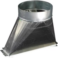
| Optional Accessories | BS series backdraft damper, backsplash, soffits, outlet adapters |
| Warranty | 1 year parts and labor, 5 years fan/motor (original purchaser) |
| Replacement Parts | Available: wiring box, switches, bulbs, filters, grease tray, etc. (see manual) |
| Repairability | Technical support at 1-800-465-7300 (Monday-Friday 8am-4pm EST) |
Frequently Asked Questions - OA8VD Air King
User questions about OA8VD Air King
0 question about this device. Answer the ones you know or ask your own.
Ask a new question about this device
Download the instructions for your Kitchen hood in PDF format for free! Find your manual OA8VD - Air King and take your electronic device back in hand. On this page are published all the documents necessary for the use of your device. OA8VD by Air King.
USER MANUAL OA8VD Air King
IMPORTANT INSTRUCTIONS - OPERATING MANUAL
Professional Series

Range Hood
READ AND SAVE THESE INSTRUCTIONS
READ CAREFULLY BEFORE ATTEMPTING TO ASSEMBLE, INSTALL, OPERATE OR MAINTAIN THE PRODUCT DESCRIBED. PROTECT YOURSELF AND OTHERS BY OBSERVING ALL SAFETY INFORMATION. FAILURE TO COMPLY WITH INSTRUCTIONS COULD RESULT IN PERSONAL INJURY AND/OR PROPERTY DAMAGE!
RETAIN INSTRUCTIONS FOR FUTURE REFERENCE.
GENERAL SAFETY INFORMATION
When using electrical appliances, basic precautions should always be followed to reduce the risk of fire, electric shock and injury to person, including the following:
WARNING: TO REDUCE THE RISK OF FIRE, ELECTRIC SHOCK, AND INJURY TO PERSONS, PROFESSIONAL SERIES RANGEHOODS MUST BE INSTALLED WITH PROFESSIONAL SERIES RANGEHOOD BLOWERS THAT ARE MARKED (ON THEIR CARTONS) TO INDICATE THE SUITABILITY WITH THIS MODEL. OTHER BLOWERS CANNOT BE SUBSTITUTED.
- Read all instructions before installing or using range hood.
- Use this unit only in the manner intended by the manufacturer. If you have questions, contact the manufacturer.
- Before servicing or cleaning the unit, switch power off at service panel and lock the service disconnecting means to prevent power from being switched on accidentally. When the service disconnecting means cannot be locked, securely fasten a prominent warning device, such as a tag, to the service panel.
- This unit must be grounded.
- To avoid motor bearing damage and noisy and/or unbalanced impellers, keep drywall spray, construction dust, etc. off power unit.
WARNING: TO REDUCE THE RISK OF FIRE, ELECTRIC SHOCK AND INJURY TO PERSON, OBSERVE THE FOLLOWING:
a.) Installation work and electrical wiring must be done by qualified person(s) in accordance with all applicable codes and standards, including fire-related construction.
b.) Sufficient air is needed for proper combustion and exhausting of gases through the flue (chimney) of fuel burning equipment to prevent back drafting. Follow the heating equipment manufacturer's guideline and safety standards such as those published by the National Fire Protection Association (NFPA) and the American Society for Heating, Refrigeration, and Air Conditioning Engineers (ASHRAE), and the local code authorities.
c.) When cutting or drilling into wall or ceiling, do not damage electrical wiring and other hidden utilities.
d.) Ducted fans must always be vented to the outdoors.
CAUTION: FOR GENERAL VENTILATING USE ONLY. DO NOT USE TO EXHAUST HAZARDOUS OR EXPLOSIVE MATERIALS AND VAPORS.
CAUTION: TO REDUCE THE RISK OF FIRE AND TO PROPERLY EXHAUST AIR, BE SURE TO DUCT AIR OUTSIDE - DO NOT VENT EXHAUST AIR INTO SPACES WITHIN WALLS OR CEILINGS OR INTO ATTICS, CRAWL SPACES, OR GARAGES.
CAUTION: TO REDUCE THE RISK OF FIRE AND ELECTRIC SHOCK, INSTALL THIS RANGEHOOD ONLY WITH INTEGRAL BLOWERS MANUFACTURED BY AIR KING, MODEL(S) B1125, B900, B600, B500, OR B300 ONLY.
WARNING: TO REDUCE THE RISK OF FIRE, ELECTRIC SHOCK, DO NOT USE THIS FAN WITH ANY SOLID-STATE SPEED CONTROL DEVICE.
WARNING: TO REDUCE THE RISK OF A RANGE TOP GREASE FIRE:
a) Never leave surface units unattended at high settings. Boilovers cause smoking and greasy spillovers that may ignite. Heat oils slowly on low or medium settings.
b) Always turn hood ON when cooking at high heat or when flambéing food (ie. Crepes Suzette, Cherries Jubilee, Peppercorn Beef Flambé).
c) Clean ventilating fans frequently. Grease should not be allowed to accumulate on fan filter.
d) Use proper pan size. Always use cookware appropriate for the size of the surface element.
WARNING: TO REDUCE THE RISK OF INJURY TO PERSONS IN THE EVENT OF A RANGE TOP GREASE FIRE, OBSERVE THE FOLLOWING:
a) SMOTHER FLAMES with a close-fitting lid, cookie sheet, or metal tray, then turn off burner. BE CAREFUL TO PREVENT BURNS. If the flames do not go out immediately, EVACUATE AND CALL THE FIRE DEPARTMENT.
b) NEVER PICK UP A FLAMING PAN - You may be burned.
c) DO NOT USE WATER, including wet dishcloths or towels - a violent steam explosion will result.
d) Use an extinguisher ONLY if:
I. You know you have a Class ABC extinguisher, and you already know how to operate it.
II. The fire is small and contained in the area where it started.
III. The fire department is being called.
IV. You can fight the fire with your back to an exit.
WARNING: TO REDUCE THE RISK OF FIRE, USE ONLY METAL DUCTWORK.
INSTALLATION INSTRUCTIONS
CAUTION: MAKE SURE POWER IS SWITCHED OFF AT SERVICE PANEL BEFORE STARTING INSTALLATION.
SECTION 1
Preparing the Range Hood
- Unpack hood from the carton and confirm that all pieces are present. In addition to the range hood you should have:
1 - Package containing:
3 - 2" wood screws
8 - 3/4" wood screws (36" models: 12 / 42", 48" models: 16)
4 - wall anchors (36" models: 6 / 42", 48" models: 8)
30" models: 2 - PHGB3 large baffles, one spacer
36" models: 2 - PHGB3 large baffles, one PHGB1 small baffle
42" models: 2 - PHGB3 large baffles, one PHGB2 medium baffle
48" models: 2 - PHGB3 large baffles, two spacer
1 - Grease trough
1 - Wood mounting strip
1 - Mounting template
1 - Instruction/Safety Sheet
NOTE: Some hoods may be shipped with a protective plastic adhered to the range hood. It is recommended to leave this in place during installation to protect the hood from scratching. Remove when the installation is complete.
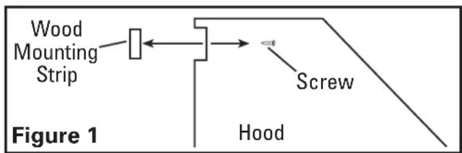
- Remove the wood mounting strip attached to the back of the hood and place in a secure place. You will need this strip later (Figure 1).
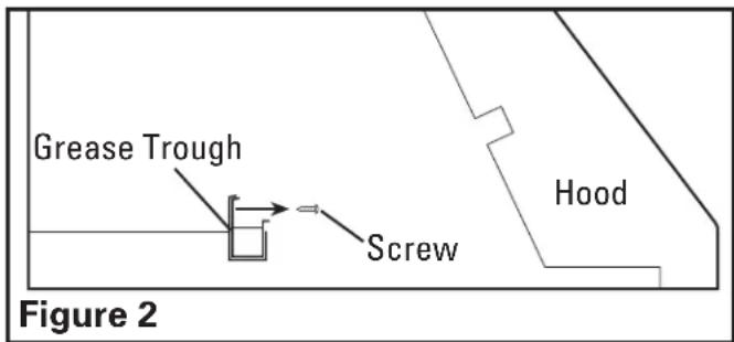
- Remove the two screws securing the grease trough in place. These have been installed for protection during shippingg (Figure 2).
CAUTION: MAKE SURE POWER IS SWITCHED OFF AT SERVICE PANEL BEFORE STARTING INSTALLATION.
CAUTION: WHEN CUTTING OR DRILLING INTO WALL DO NOT DAMAGE ELECTRICAL WIRING AND OTHER HIDDEN UTILITIES.
SECTION 2
Measuring the Hood Installation
NOTE: Before installing any parts or marking locations, make sure you have decided how your ducting will be installed. You may need to modify the wall structure as described in Section 5 Wall Mounted Canopy Installation or Section 6 Under Cabinet Canopy Installation.
- The measurements for the installation will be custom to your specific location and will be dependent upon exact ceiling height, distance mounted from cooking surface, cabinet or soffit heights, along with other factors and will need to be adjusted accordingly. The hood must be mounted a minimum of 24" and a maximum of 36" from the cooking surface. (Figure 3).
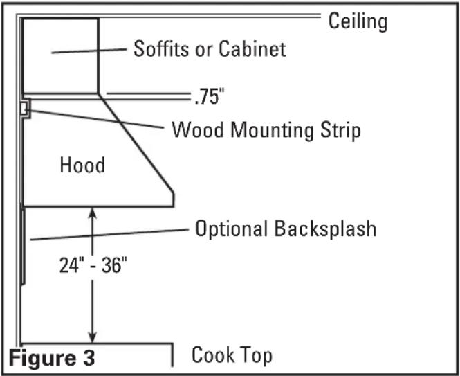
NOTE: When determining the height of the canopy from the cooking surface, be sure to take into consideration items such as back splashes with shelves and other accessories that might need more clearance under the canopy.
SECTION 3
Measuring the Installation
- Determine where the top of the hood will be located within your installation and tape the included wall mounting template in place (Figure 4).
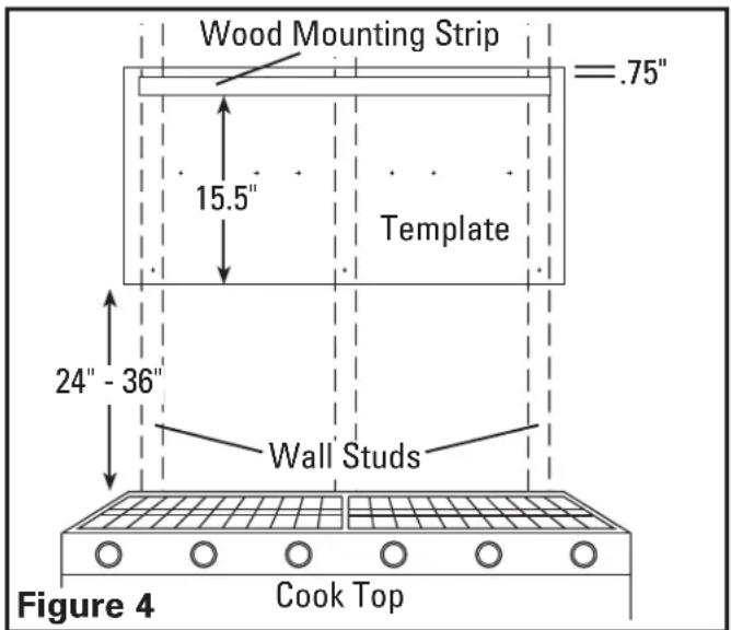
- Using the template as a guide, place the wood strip that was removed in Section 1 Step 2 on top of the template and confirm it is level. Secure in place using the provided 2" mounting screws making sure the screws are fastening into the wall studs (Figure 5).
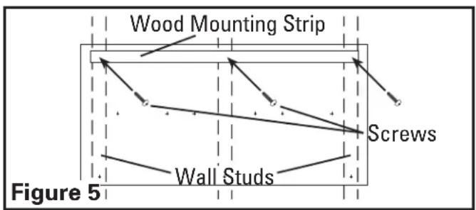
CAUTION: DUE TO THE WEIGHT OF THE HOOD, ENSURE THE WOOD STRIP IS FASTENED TO ALL AVAILABLE WALL STUDS (A MINIMUM OF 2 STUDS FOR 30" HOODS, MORE AS THE WIDTH INCREASES) NOT INTO THE DRYWALL ALONE.
CAUTION: SUPPORT THE HOOD UNTIL IT IS FULLY INSTALLED ONTO THE WOOD MOUNTING STRIP.
- Install wall anchors by drilling holes at the marked locations on the template then installing the anchors in place. An alternative method is to rest the cavity in the back side of the hood on the wood strip and mark drilling locations on the wall for wall anchors on the bottom rear of the hood then remove hood and install wall anchors (Figure 6).
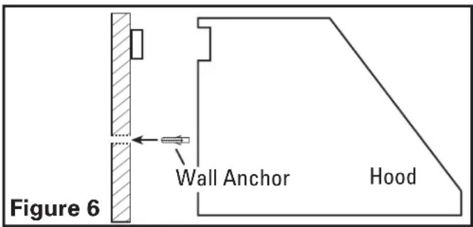
SECTION 4
Installing Backsplash
- If an optional BS Series backsplash will be utilized, this must be installed before the hood canopy because the hood canopy will cover the backsplash mounting screws. Refer to the instructions included with the backsplash for installation.
SECTION 5
Wall Mounted Canopy Installation
CAUTION: ALL DUCTING MUST COMPLY WITH LOCAL AND NATIONAL BUILDING CODES.
WARNING: TO REDUCE THE RISK OF FIRE, USE ONLY METAL DUCTWORK.
- Determine the type of ducting you will require (Figure 7).
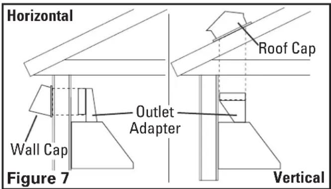
NOTE: When the duct termination is similar to that shown in figure 7 (passing through the wall to which the hood is mounted) the installation requires special consideration. Depending upon where the wall studs are located, it may be necessary to cut one or more of the wall studs and install a header and footer to transfer the load to the adjacent studs. Additional studs may need to be framed into the opening to attach dry wall or secure the hood. If this is your situation Air King recommends that you hire a professional and comply with all applicable codes.
- Install the proper sized outlet adapter (available separately) to the hood by matching up the four holes on the flange of the adapter to the four corresponding holes on the hood and secure in place with the provided screws. Ensure an airtight seal around the adapter by securing all connections with ducting tape (Figure 8).
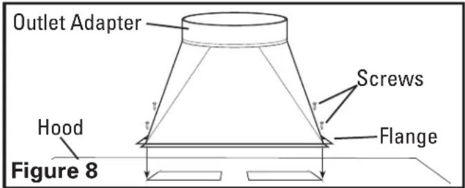
- It is highly recommended that a back draft damper be installed to prevent outside air from flowing back into the home. Choose a back draft damper (available separately) sized to fit the diameter of the outlet adapter. Attach the back draft damper into the outlet adapter, press fit it into the round opening of the adapter until it is fully seated, making sure the damper opens away from the hood otherwise airflow will be restricted (Figure 9).
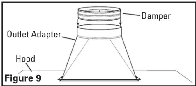
NOTE: If the recommended, optional BS Series backsplash is being installed, use the template to locate and drill the appropriate holes for mounting. The back splash must be installed before the hood canopy because the hood canopy will cover the backsplash mounting screws. Refer to the instructions included with the backsplash for complete installation instructions.
- Rest the cavity in the back side of the hood on the wood strip and secure hood to wood strip with the included 3/4" screws through the holes in the back of the hood that line up with the wood strip (use 6 screws for 30" and 36" widths and 8 screws for larger widths) Secure the bottom of the hood by installing the screws provided into the wall anchors. (Figure 10).
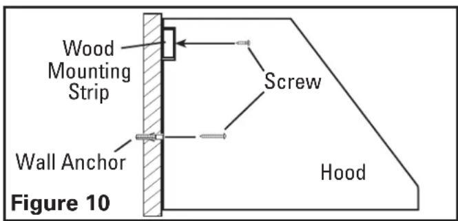
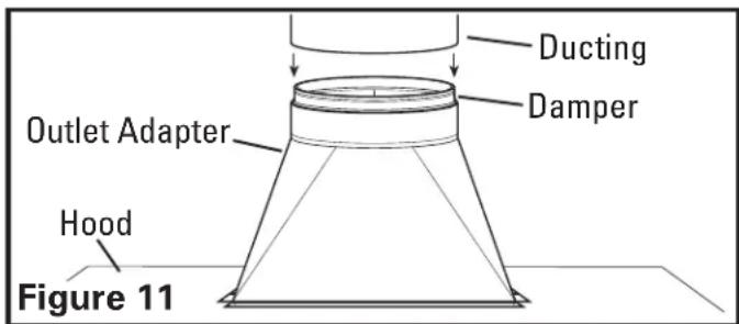
- Connect the ducting to the outlet adapter and damper. Secure in place using tape to seal all joints (Figure 11).
SECTION 6
Under Cabinet Canopy Installation
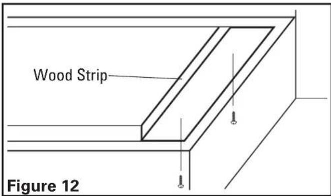
- If the canopy will be installed under cabinets that have a recessed bottom, it will be necessary to install wood mounting strips (not included) so the canopy will mount properly (Figure 12).
-
The thickness of the strips should be the same as the recess of the cabinet and they should be approximately 2irc wide.
-
Install the strips using appropriate length wood screws (not included). Make sure the strips line up to the holes in the top of the canopy.
-
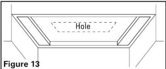
Mark the location where the outlet adapter (available separately) will be located on the cabinets and cut a hole approximately 1" larger on all sides than the outlet adapter (Figure 13).
NOTE: If the recommended, optional BS Series backsplash is being installed, use the template to locate and drill the appropriate holes for mounting. The back splash must be installed before the hood canopy because the hood canopy will cover the backsplash mounting screws. Refer to the instructions included with the backsplash for complete installation instructions.
- Rest the cavity in the back side of the hood on the wood strip and secure hood to wood strip with the included 3/4" screws through the holes in the back of the hood that line up with the wood strip (use 6 screws for 30" and 36" widths and 8 screws for larger widths) Secure the bottom of the hood by installing the screws provided into the wall anchors (Figure 14).
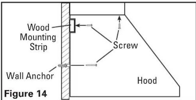
- From inside the hood canopy, secure hood to the underside of the cabinet by using four wood screws (not included) through the keyhole slots of the hood (Figure 14).
CAUTION: ALL DUCTING MUST COMPLY WITH LOCAL AND NATIONAL BUILDING CODES.
WARNING: TO REDUCE THE RISK OF FIRE, USE ONLY METAL DUCTWORK.
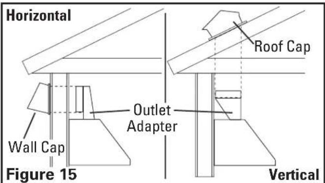
- Determine the type of ducting you will require (Figure 15).
NOTE: When determining the outlet adapter to be used, make sure to consider the clearance within the cabinet space. Typically a horizontal Outlet Adapter will need to be used if you will be venting out to a wall cap.
NOTE: When the duct termination is similar to that shown in figure 15 (passing through the wall to which the hood is mounted) the installation requires special consideration. Depending upon where the wall studs are located, it may be necessary to cut one or more of the wall studs and install a header and footer to transfer the load to the adjacent studs. Additional studs may need to be framed into the opening to attach dry wall or secure the hood. If this is your situation Air King recommends that you hire a professional and comply with all applicable codes.
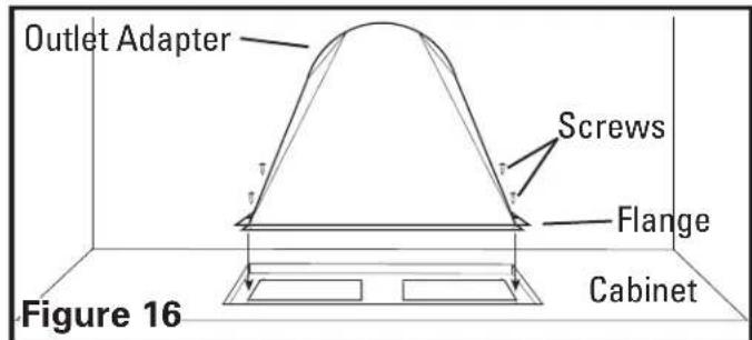
- Install the proper sized outlet adapter (available separately) to the hood by sliding it down into the hole cut earlier and matching up the four holes on the flange of the adapter to the four corresponding holes on the hood and secure in place with the provided screws. Ensure an airtight seal around the adapter by securing all connections with ducting tape (Figure 16).
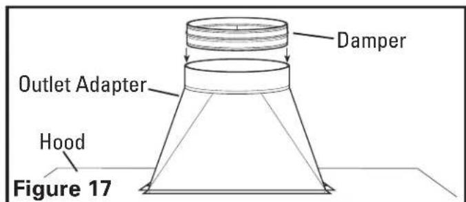
- It is highly recommended that a back draft damper be installed to prevent outside air from flowing back into the home. Choose a back draft damper (available separately) sized to fit the diameter of the outlet adapter. Attach the back draft damper into the outlet adapter, press fit it into the round opening of the adapter until it is fully seated, making sure the damper opens away from the hood otherwise airflow will be restricted (Figure 17).
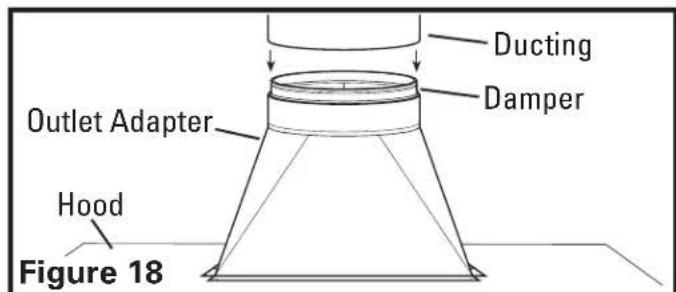
- Connect the ducting to the outlet adapter and damper. Secure in place using tape to seal all joints (Figure 18).
SECTION 7
Wiring
CAUTION: ALL ELECTRICAL CONNECTIONS MUST BE MADE IN ACCORDANCE WITH LOCAL CODES, ORDINANCES, OR NATIONAL ELECTRICAL CODE. IF YOU ARE UNFAMILIAR WITH METHODS OF INSTALLING ELECTRICAL WIRING, SECURE THE SERVICES OF A QUALIFIED ELECTRICIAN.
-
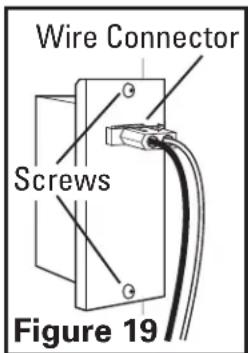
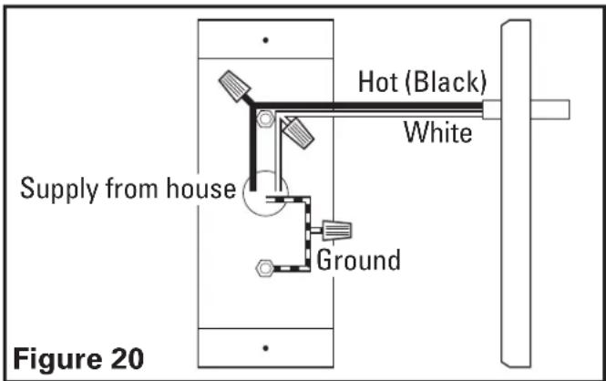
Remove the two wire compartment cover screws to gain access into the wire compartment (Figure 19). Connect the white wire from the range hood to the white wire from the supply, and the black wire from the range hood to the black wire of the supply. Connect the ground wire from the home (green or bare) to the ground wire (green) from the hood. Use approved methods for all connections (Figure 20).
-
Replace the wire compartment cover and tighten screws. Make sure all wiring is securely contained within the wire compartment. If the quick connect wire connector was removed from the receptacle, replace. The connector will only fit one way into the receptacle (Figure 19).
SECTION 8
Installing the Optional Soffits
- Refer to the instructions included with the specific soffit(s) you have chosen for installation.
SECTION 9
Installing the Blower
- Refer to the instructions included with the specific blower you have chosen for installation.
SECTION 10
Finishing the Installation
- Install the proper lighting for your specific unit:
Halogen Lamps: Use PAR16, 45W maximum lamps (available separately). Install by inserting lamp into socket and turning clockwise until lamp is firmly seated. DO NOT over tighten.
Heat Lamps: Use PAR38, 175W infrared lamps only (available separately). Install by inserting lamp into socket and turning clockwise until lamp is firmly seated. DO NOT over tighten.
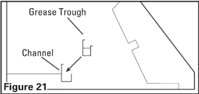
- If the included removable grease trough is not already installed within the hood, insert into the rear inside channel of the hood. Make sure the taller side of the trough is facing towards the back of the hood (Figure 21).
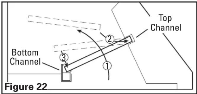
- Install the baffle filters along with any spacer bars that are required by inserting the top of the filter into the top channel of the hood, then slide the bottom of the filter into the bottom channel. The filters have a top and a bottom. The bottom of the filter will have small drain holes. These holes must be facing down towards the grease trough to be effective. In models with spacers, it is easiest to install the spacer(s) first and the grease filters last (Figure 22).
SECTION 11
Operation
Controls
Your Range Hood is equipped with two rotary switches with one controlling the lighting and the other controlling the exhaust fan blower. The light switch has three positions, HIGH (★), LOW (★) and OFF (★). The fan switch has four positions, OFF (●), HIGH (III), MEDIUM (II), and LOW (II) (Figure 23).
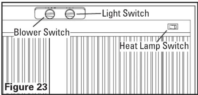
NOTE: On installation where a One (1) speed blower is utilized, all blower control speeds operate at the same speed. On installation where a Two (2) speed blower is utilized, the Medium and High speeds operate at the same speed.
Heat Lamp Controls: For models equipped with heat lamps, two On/Off rocker switch are located on the front underside of the hood for independent control of the heat lamps (Figure 23).
SECTION 12
Maintenance
CAUTION: MAKE SURE POWER IS SWITCHED OFF AT SERVICE PANEL BEFORE SERVICING THE UNIT.
Grease Baffles - Included with your range hood are stainless steel grease baffles along with a grease trough that should be washed at least once a month. The baffles and trough are dishwasher safe and should be washed in a mild soap or detergent. Reverse the instruction in SECTION 10 Finishing the Installation, to remove baffles and trough. If the grease baffles become damaged, replace with Air King Model PHGB1, PHGB2, or PHGB3 Grease Baffles.
CAUTION: ALLOW BULB TO COOL BEFORE REPLACING.
Changing the Lamps: Disconnect power to the unit and unscrew lamps from socket. Replace with lamps as specified in SECTION 10 Finishing the Installation.
Cleaning
CAUTION: DO NOT USE GASOLINE, BENZINE, THINNER, HARSH CLEANSERS, ETC., AS THEY MAY DAMAGE THE RANGE HOOD.
-
Clean your range hood with a mild detergent, such as dishwashing liquid, and dry with a soft cloth. NEVER USE ANY ABRASIVE PADS OR SCOURING POWDERS. Completely dry before restoring power. NEVER IMMERSE ELECTRICAL PARTS IN WATER.
-
The blower assembly can be vacuumed when build up (dirt, lint, etc.) accumulates over time. The blower is permanently lubricated and does not require oiling.
Troubleshooting Guide
| 1. Hood does not operate when the switch is on. | 1a. A fuse may be blown or a circuit tripped.1b. Wiring is not connected properly. 1b. Turn off power to unit. Check that all wires are connected. | 1a. Replace fuse or reset circuit breaker. |
| 2. Hood is operating, but air moves slower than normal. | 2. Obstruction in the exhaust ducting. | 2. Check for any obstructions in the ducting including filter. |
| 3. Hood is making a rattling noise. | 3a. Filters are loose.3b. Duct connection is loose. 3b. Turn off power to unit. Check that all filters are fully seated. | 3a. Turn off power to unit. Check that all filters are fully seated. |
LIMITED WARRANTY
All products manufactured by Air King Limited are warranted for one year from the date of purchase against defects in workmanship and/or material. In addition, all ventilating/exhaust fans, heaters, combination fan lights and/or heaters, and range hoods are guaranteed for five years from the date of purchase against defects in workmanship and/or material.
This warranty does not cover any labor or shipping costs or the cost of replacement components as part of routine maintenance such as: range hood grease filters, charcoal filters or combination charcoal/grease filters; replacement light bulbs in range hoods or bathroom fan/light/bulb heater combinations. As well, any damage or failure caused by abuse, misuse, abnormal usage, faulty installation, or improper maintenance will not be covered by this warranty.
In order to make a claim on this warranty, you must be the original consumer of the product. You will be required to present to Air King the original bill of sale showing: date of purchase, place of purchase and model purchased. Failure to meet these requirements will void your warranty.
Air King will not be held responsible for any bodily injury or damages to personal property or real estate whether caused directly or indirectly by the product. Some states and provinces do not allow the exclusion or limitation of incidental or consequential damages and some states do not allow limitations on how long an implied warranty lasts, so these exclusions or limitations may not apply to you. This warranty gives you specific legal rights and you may have other rights which vary from state to state and province to province.
FOR PARTS OR TECHNICAL ASSISTANCE
Please call: 1-800-465-7300, MONDAY THROUGH FRIDAY, BETWEEN THE HOURS OF 8 AM AND 4:00 PM EST. PLEASE DO NOT RETURN PRODUCT TO PLACE OF PURCHASE.
Reference the type and style of product (located on label inside of the product) when you call. For more information please visit our website: wwwairkinglimited.com
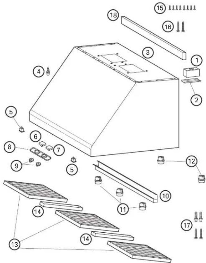
| # | Qty. | Description Replacement Part # | |
| 1 | 1 | Wire Box | 5S1136064 |
| 2 | 1 | Wire Box Cover 5S1136065 | |
| 3 | 1 | Canopy | 5S1136067 |
| 4 | 1 | Fuse | 5S1136068 |
| 5 | 2* | Heat Lamp Switch 5S1136069 | |
| 6 | 1 | Rotary Fan Switch | 5S1136070 |
| 7 | 1 | Rotary Light Switch | 5S1136071 |
| 8 | 1 | Switch Plate | 5S1136072 |
| 9 | 2 | Knob | 5S1136073 |
| 10 | 1 | Grease Trough - 30" | 5S1136074 |
| Grease Trough - 36° | 5S1136089 | ||
| Grease Trough - 42° | 5S1136090 | ||
| Grease Trough - 48° | 5S1136091 | ||
| 11 | ** | Halogen Lamp Holder | 5S1136075 |
| 12 | 1* | Heat Lamp Holder | 5S1136076 |
| 13 | ** | Baffle Filter - PHGB1 | 5S1136077 |
| Baffle Filter - PHGB2 | 5S1136078 | ||
| Baffle Filter - PHGB3 | 5S1136079 | ||
| 14 | ** | Filter Spacer - 30" Series | 5S1136080 |
| Filter Spacer - 48" Series | 5S1136081 | ||
| 15 | ** | 3/4" Screw | 5S1136086 |
| 16 | ** | 2" Wood Screw 5S1136087 | |
| 17 | ** | #8 Screw w/Wall Anchor | 5S1136088 |
| 18 | 1 | Wood Mounting Strip | 5S1136084 |
* Models with Heat Lamps Only
** Quantity will vary depending on specific model
INSTRUCTIONS IMPORTANTES - MANUEL D'OPÉRATION
Finishing the Installation
- IMPORTANT INSTRUCTIONS - OPERATING MANUAL
- READ AND SAVE THESE INSTRUCTIONS
- RETAIN INSTRUCTIONS FOR FUTURE REFERENCE.
- GENERAL SAFETY INFORMATION
- INSTALLATION INSTRUCTIONS
- SECTION 1
- Preparing the Range Hood
- SECTION 2
- Measuring the Hood Installation
- SECTION 3
- Measuring the Installation
- CAUTION: SUPPORT THE HOOD UNTIL IT IS FULLY INSTALLED ONTO THE WOOD MOUNTING STRIP.
- SECTION 4
- Installing Backsplash
- SECTION 5
- Wall Mounted Canopy Installation
- WARNING: TO REDUCE THE RISK OF FIRE, USE ONLY METAL DUCTWORK.
- SECTION 6
- Under Cabinet Canopy Installation
- CAUTION: ALL DUCTING MUST COMPLY WITH LOCAL AND NATIONAL BUILDING CODES.
- SECTION 7
- SECTION 8
- SECTION 9
- SECTION 10
- SECTION 11
- SECTION 12
- CAUTION: ALLOW BULB TO COOL BEFORE REPLACING.
- Cleaning
- LIMITED WARRANTY
- FOR PARTS OR TECHNICAL ASSISTANCE
- INSTRUCTIONS IMPORTANTES - MANUEL D'OPÉRATION
Brand : Air King
Model : OA8VD
Category : Kitchen hood