
BDSTGA9701 - Rice cooker BLACK & DECKER - Free user manual and instructions
Find the device manual for free BDSTGA9701 BLACK & DECKER in PDF.

| Product Type | Rotating Drum Composter |
| Brand | Black & Decker |
| Model | BDSTGA9701 |
| Maximum Capacity | 60 lb (27 kg) |
| Main Material | Plastic |
| Dimensions (approx.) | Height 90 cm, Width 60 cm, Depth 60 cm |
| Weight (approx.) | 15 kg |
| Operation | Manual (crank rotation) |
| Number of Chambers | 2 (with divider) |
| Doors | 2 (add door and harvest door) |
| Adjustable Vents | Yes |
| Rotation Lock | Yes |
| Assembly Required | Yes |
| Intended Use | Household use only |
| Warranty | 2 years limited |
| Maintenance | Clean with damp cloth and mild soap |
| Safety | Rotation lock, pinch protection |
| Recommended Accessories | Original Black & Decker parts |
| Repairs | Authorized Black & Decker service center |
Frequently Asked Questions - BDSTGA9701 BLACK & DECKER
User questions about BDSTGA9701 BLACK & DECKER
0 question about this device. Answer the ones you know or ask your own.
Ask a new question about this device
Download the instructions for your Rice cooker in PDF format for free! Find your manual BDSTGA9701 - BLACK & DECKER and take your electronic device back in hand. On this page are published all the documents necessary for the use of your device. BDSTGA9701 by BLACK & DECKER.
USER MANUAL BDSTGA9701 BLACK & DECKER
Tumbling Composter Assembly Instructions
natural_image
Line drawing of a black-and-white industrial machine with a rotating wheel and mounting bracket (no text or symbols)Table of Contents | Table des Matières | Tabla de Contenido
INSTRUCTION MANUAL....3
WARNING....5
Assembly Instructions....6
Materials 6
Section 1: Assemble the Composter Barrel ....8
Section 2: Assemble the Base ....15
Section 3: Install the Composter Barrel on the Base 20
Features 23
About Composting 24
Section 2: Assembler la Base ....37
Please read before returning this product for any reason.

WARNING: Read all safety warnings and all instructions. Failure to follow the warnings and instructions may result in electric shock, fire and/or serious injury.

WARNING: To reduce the risk of injury, read the instruction manual.
Intended Use
Your BLACK+DECKER, BDSTGA9701 has been designed for household, consumer use only. This barrel composter is designed to mix typical green and brown compostables.
DO NOT let children come into contact with the product. Supervision is required when inexperienced operators use this product.
Definitions: Safety Alert Symbols and Words
This instruction manual uses the following safety alert symbols and words to alert you to hazardous situations and your risk of personal injury or property damage.

DANGER: Indicates an imminently hazardous situation which, if not avoided, will result in death or serious injury.

WARNING: Indicates a potentially hazardous situation which, if not avoided, could result in death or serious injury.

CAUTION: Indicates a potentially hazardous situation which, if not avoided, may result in minor or moderate injury.

(Used without word) Indicates a safety related message.

NOTICE: Indicates a practice not related to personal injury which, if not avoided, may result in property damage.
Composting Safety Warnings

WARNING: Failure to follow these warnings may result in serious personal injury or property damage.

CAUTION: Rotating gears can pinch fingers.

CAUTION: Opening or closing the doors can pinch fingers.
- Use care when using sharp objects to remove compost to avoid damaging the composter barrel.
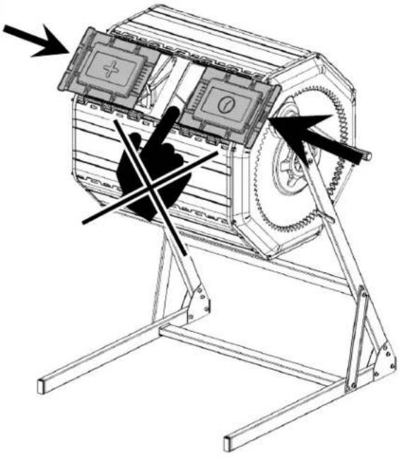
• Do not rotate composter barrel with doors open.
• Stand clear of handle as it may spin fast.
• Assemble on a smooth, level surface. - Wear appropriate gloves and eye protection when using and assembling composter.
- Keep hands and loose clothing away from the composter barrel when rotating.
-
Keep children away from the composter.
-
Remove the composter barrel from the frame before moving or relocating the unit.
- Remove composter barrel doors when emptying compost.
- Be aware that plastic panels can be damaged by over tightening the connections.
- Do not overload the composter barrel. The maximum composter barrel load is 60 lbs.
- Do not rotate the composter barrel when compost material is frozen.
• Do not climb on, in, or around the composter.
• Do not use or store hot objects near the plastic composter.
Additional Safety Information

WARNING: Never modify the product or any part of it. Damage or personal injury could result.

WARNING: ALWAYS use safety glasses. Everyday eyeglasses are NOT safety glasses. Also use face or dust mask if operation is dusty. ALWAYS WEAR CERTIFIED SAFETY EQUIPMENT:
• ANSI Z87.1 eye protection (CAN/CSA Z94.3),
• ANSI S12.6 (S3.19) hearing protection,
• NIOSH/OSHA/MSHA respiratory protection.

WARNING: Some dust contains chemicals known to State of California to cause cancer, birth defects or other reproductive harm. Some examples of these chemicals are:
• compounds in fertilizers,
• compounds in insecticides, herbicides and pesticides,
• arsenic and chromium from chemically treated lumber.
To reduce your exposure to these chemicals, wear approved safety equipment such as dust masks that are specially designed to filter out microscopic particles.

WARNING: Use of this product can generate and/or disperse dust, which may cause serious and permanent respiratory or other injury. Always use NIOSH/OSHA approved respiratory protection appropriate for the dust exposure. Direct particles away from face and body.
• Air vents often cover moving parts and should be avoided. Loose clothes, jewelry or long hair can be caught in moving parts.
MAINTENANCE

WARNING: To reduce the risk of serious personal injury, wear gloves and protective eye wear before assembling, making any adjustments or removing/installing attachments or accessories. Failure to follow these warnings may result in serious personal injury or property damage.
Your BLACK+DECKER product has been designed to operate over a long period of time with a minimum of maintenance. Continuous satisfactory operation depends upon proper care and regular cleaning.
Cleaning

WARNING: Blow dirt and dust out of all air vents with clean, dry air at least once a week. To minimize the risk of eye injury, always wear ANSI Z87.1 approved eye protection when performing this procedure.

WARNING: Never use solvents or other harsh chemicals for cleaning the non-metallic parts of the tool. These chemicals may weaken the plastic materials used in these parts. Use a cloth dampened only with water and mild soap. Never let any liquid get inside the tool; never immerse any part of the tool into a liquid.
Accessories

WARNING: Since accessories, other than those offered by BLACK+DECKER, have not been tested with this product, use of such accessories with this product could be hazardous. To reduce the risk of injury, only BLACK+DECKER recommended accessories should be used with this product.
Recommended accessories for use with your product are available at extra cost from your local dealer or authorized service center. If you need assistance in locating any accessory, please contact BLACK+DECKER call 1-800-544-6986.
Repairs

WARNING: To assure product SAFETY and RELIABILITY, repairs, maintenance and adjustment (including brush inspection and replacement, when applicable) should be performed by a BLACK+DECKER factory service center or a BLACK+DECKER authorized service center. Always use identical replacement parts.
Register Online
Thank you for your purchase. Register your product now for: WARRANTY SERVICE: Registering your product will help you obtain more efficient warranty service in case there is a problem with your product.
CONFIRMATION OF OWNERSHIP: In case of an insurance loss, such as fire, flood or theft, your registration of ownership will serve as your proof of purchase.
FOR YOUR SAFETY: Registering your product will allow us to contact you in the unlikely event a safety notification is required under the Federal Consumer Safety Act.
Register online at www.BlackandDecker.com/NewOwner
TWO-YEAR LIMITED WARRANTY
Black & Decker (U.S.) Inc. warranties this product to be free from defects in material or workmanship for a period of two (2) years following the date of purchase, provided that the product is used in a home environment. This limited warranty does not cover failures due to abuse, accidental damage or when repairs have been made or attempted by anyone other than BLACK+DECKER and its Authorized Service Centers. A defective product meeting the warranty conditions set forth herein will be replaced or repaired at no charge in either of two ways: The first, which will result in exchanges only, is to return the product to the retailer from whom it was purchased (provided that the store is a participating retailer). Returns should be made within the time period of the retailer's policy for exchanges. Proof of purchase may be required. Please check with the retailer for its specific return policy regarding time limits for returns or exchanges. The second option is to take or send the product (prepaid) to a BLACK+DECKER owned or authorized Service Center for repair or replacement at BLACK+DECKER's option. Proof of purchase may be required. BLACK+DECKER owned and authorized service centers are listed online at www.blackanddecker.com. This warranty does not apply to accessories. This warranty gives you specific legal rights and you may have other rights which vary from state to state or province to province. Should you have any questions, contact the manager of your nearest BLACK+DECKER Service Center. This product is not intended for commercial use, and accordingly, such commercial use of this product will void this warranty. All other guarantees, express or implied, are hereby disclaimed. LATIN AMERICA: This warranty does not apply to products sold in Latin America. For products sold in Latin America, check country specific warranty information contained in the packaging, call the local company or see the website for such information.
Imported by Black & Decker (U.S.) Inc.,
701 E. Joppa Rd.
Towson, MD 21286
WARNING
| Safety glasses required for assembly | |
| NOTICE: Composting contents may stain some surfaces such as concrete or masonry. Cover or protect areas before placing composting unit on them. | |
 |  |
| Do not rotate barrel with doors open | CAUTION: Gears can pinch fingers |
 |  |
| Stand clear of handle as it may spin fast | CAUTION: Doors can pinch fingers |
Assembly Instructions
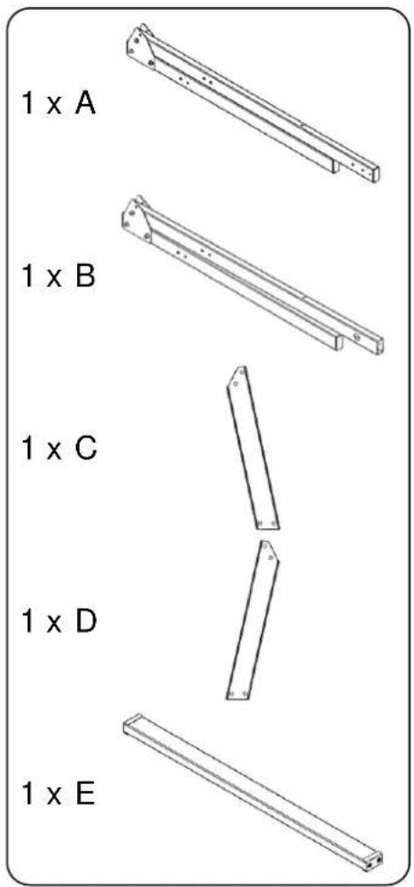
Materials
Base
| Part No. | Picture | Qty | Description |
| A | 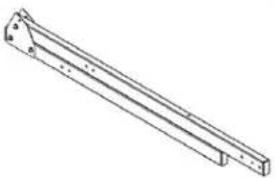 | 1 | Left arm assembly |
| B | 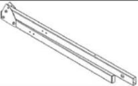 | 1 | Right arm assembly |
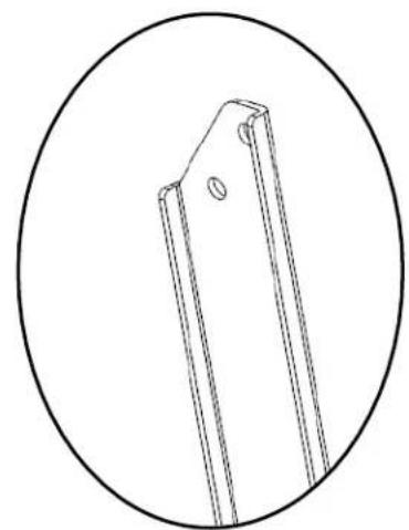
| C |  | 1 | Left side support |
| D | 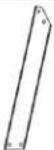 | 1 | Right side support |
| E | 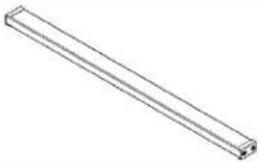 | 2 | Horizontal stabilizer bar |
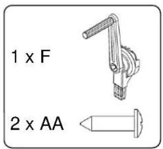
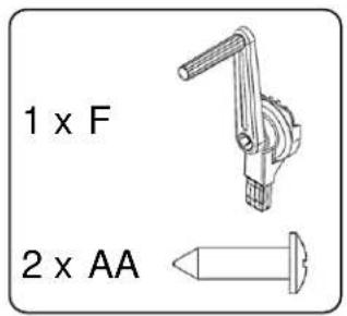
| F | 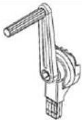 | 1 | Handle |
| G | 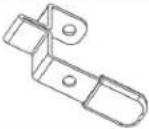 | 1 | Rotation lock |
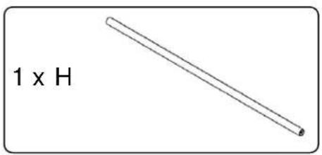
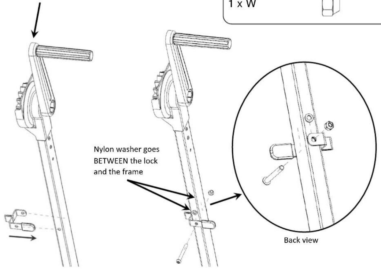
| H | 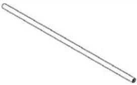 | 1 | Shaft |
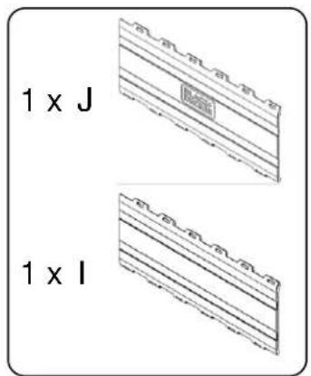
Composter barrel
| Part No. | Picture | Qty | Description |
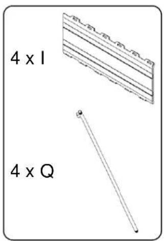
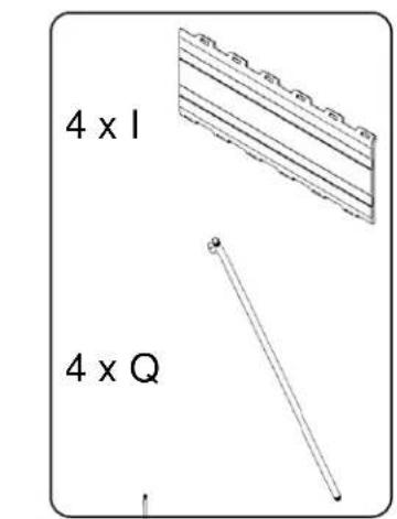
| I | 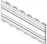 | 5 | Plain panel |
| J | 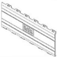 | 1 | Panel with logo |
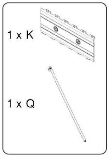
| K | 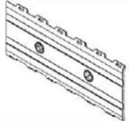 | 1 | Panel with vents |
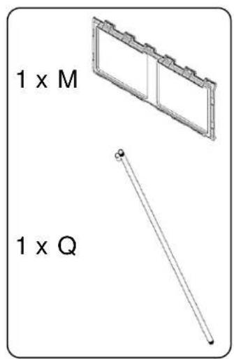
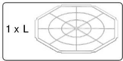
| L | 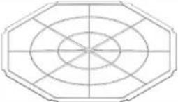 | 1 | Chamber divider |
| M | 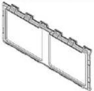 | 1 | Door base panel |
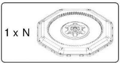
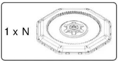
| N | 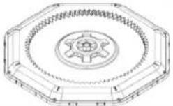 | 2 | Side cover |
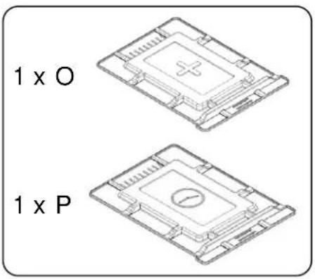
| O | 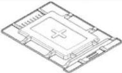 | 1 | "Add" door |
| P | 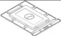 | 1 | "Time" door |
Hardware
| Part No. | Picture | Qty | Description |
| Q | 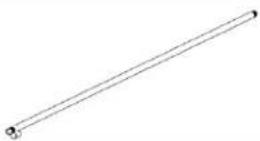 | 8 | M5 threaded rod |
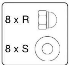
| R | 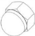 | 16 | M5 hooded nut |
| S | 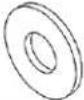 | 16 | M5 flat washer |
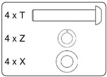
| T | 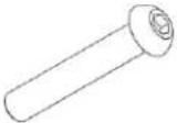 | 10 | M6x35 round head screw |
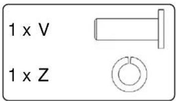
| U | 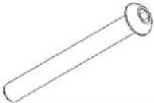 | 1 | M6x55 round head screw |
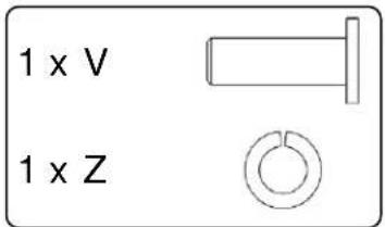
| V | 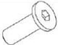 | 2 | M6x18 flat head screw |
| W | 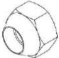 | 3 | M6 Lock nut |
| X | 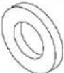 | 10 | M6 flat washer |
| Y |  | 2 | M6 nylon washer |
| Z |  | 10 | M6 open lock washer |
| AA | 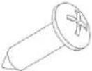 | 2 | M4x15 Self tapping screw |
Tools Included
| Picture | Description |
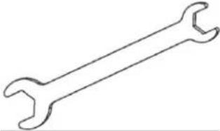 | Double sided10 mm and8 mm wrench |
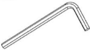 | 4 mm hex key |
Tools Needed
| Picture | Description |
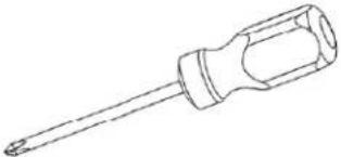 | Cross head screwdriver |
 | Safety glasses |
Section 1: Assemble the Composter Barrel
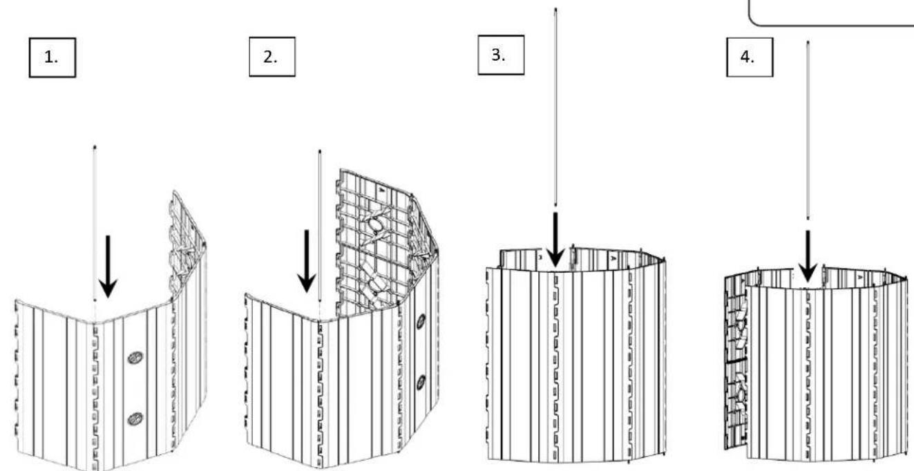
Step 1. Align the logo panel and a plain panel at a slight angle as shown so the "A" sides line up and the tabs interlock.

natural_image
Line drawing of a closed book with vertical spine and decorative side panels (no text or symbols)Orient logo as shown
"A" side
"B" side
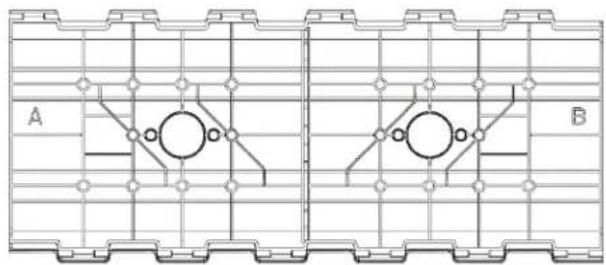
natural_image
Technical diagram of a mechanical or structural component with grid patterns and two labeled sections A and B (no text or symbols beyond labels)Underside of panel
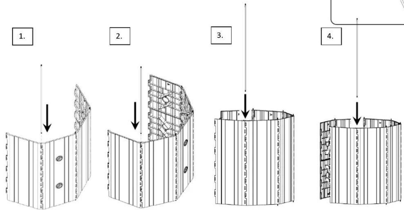
Step 2. Starting from the A side, insert one threaded rod through the hinge.


Step 3. Install the panel with air vents onto the plain panel.
Continue to align the "A" sides and insert the threaded rods from the "A" side for each panel.
Step 4. Install the remaining plain panels.
Continue to align the "A" sides and insert the threaded rods from the "A" side for each panel.
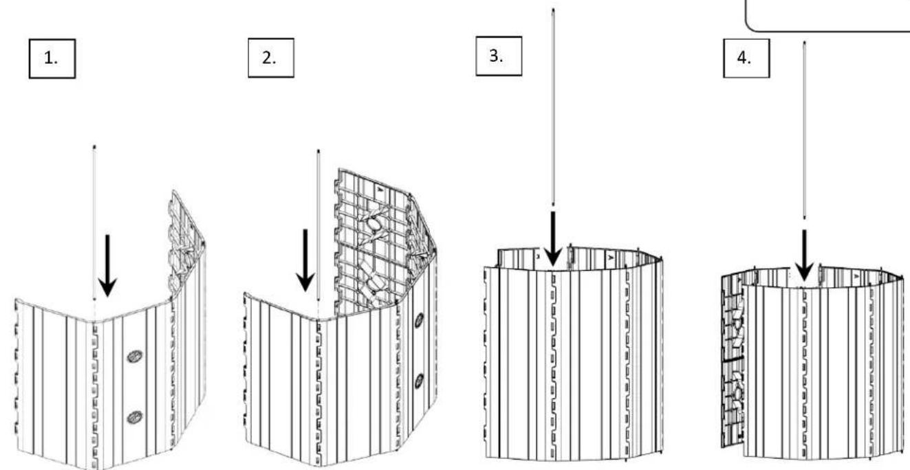
Step 5. Install ONE side of the door base panel, continuing to line up the "A" sides and insert the threaded rod from the "A" side.
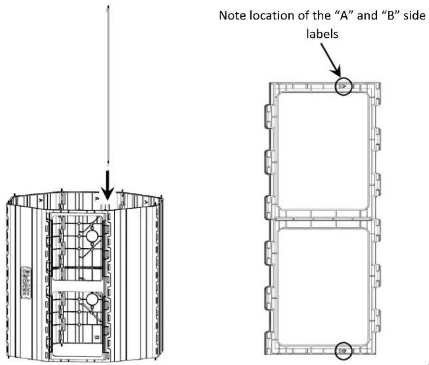
Step 6. Install the chamber divider in the center of the composter. Ensure the chamber divider is seated in the designated groove, shown on the next page.
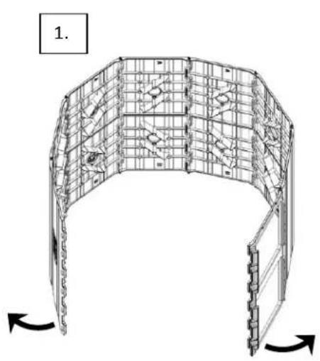
natural_image
Architectural wireframe diagram of a curved structural frame with directional arrows indicating rotation (no text or symbols)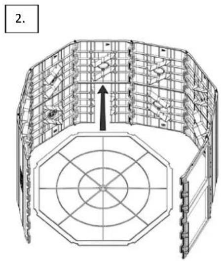
natural_image
Architectural diagram of a multi-level building structure with circular grid layout and an upward arrow indicating direction (no text or symbols)Ensure the center divider sits in groove on the door base panel

natural_image
Technical line drawing of a hexagonal mechanical or architectural structure with internal components and directional arrows (no text or symbols)Step 6 cont'd on next page
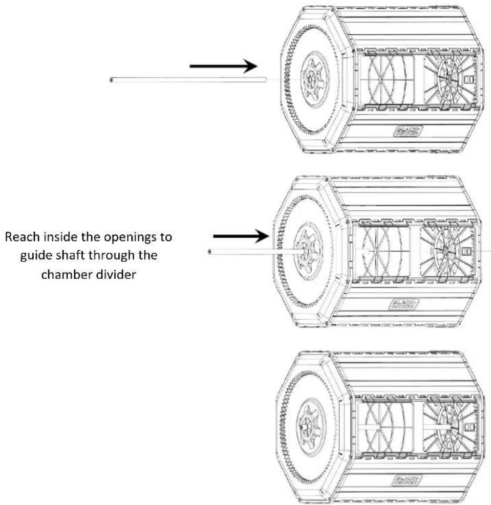
Step 6. Continued- Ensure the chamber divider is seated in the designated groove.
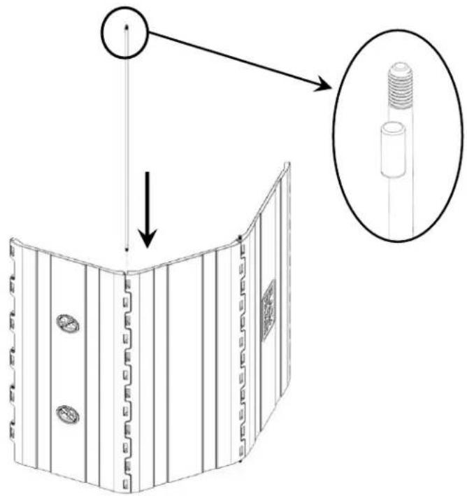
Step 7. Install the threaded rod in the remaining side of the door base panel. Insert the threaded rods from the "A" side.
natural_image
Technical line drawing of a cylindrical industrial or mechanical structure with internal components and a vertical arrow indicating direction (no text or symbols present)

natural_image
Technical line drawing of a hexagonal mechanical component with internal gear-like structure (no text or symbols)Step 8. Install one side cover to the "A" side of the barrel.
Fit the panels in the groove in the side cover and align the holes with the threaded rods in the panels.
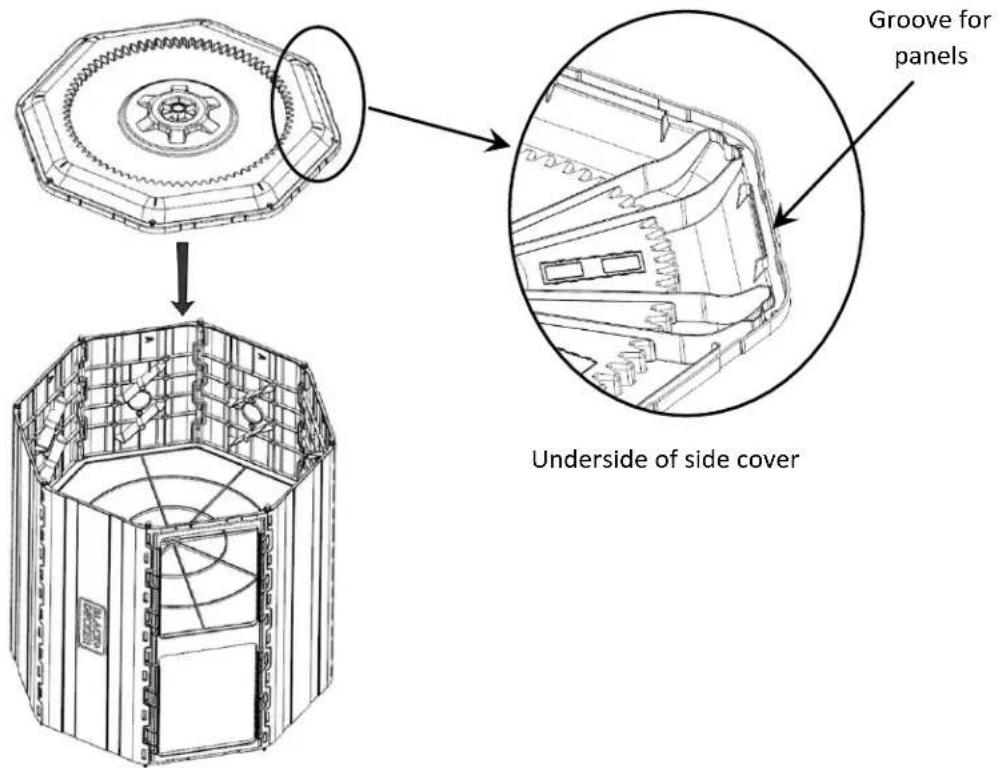
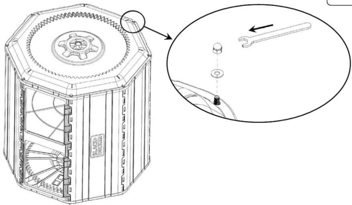
Step 9. Install the hardware on the 8 threaded rods. DO NOT FULLY TIGHTEN.
natural_image
Technical line drawing of a mechanical device with gear and mounting holes, showing internal components and a close-up inset (no text or symbols)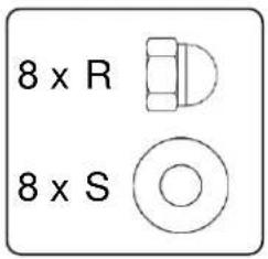
natural_image
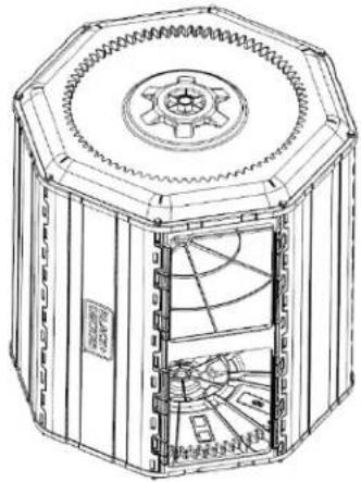
Technical line drawing of a mechanical component with a central hub and surrounding grooves (no text or symbols)Step 10. Flip the barrel over to sit on the "A" side cover and repeat step 8 to attach the "B" side cover.

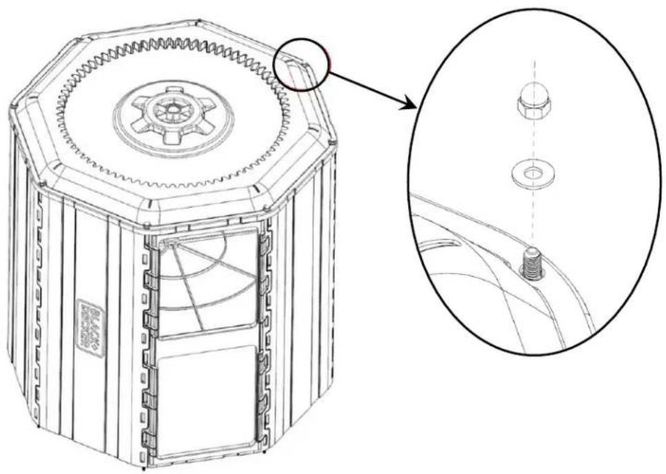
Step 11. Install the hardware on the 8 threaded rods. Tighten the fasteners with an 8 mm wrench.
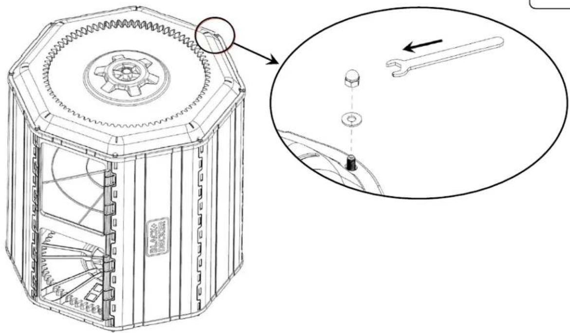
natural_image
Technical line drawing of a mechanical device with gear and internal components, showing a close-up view of the component (no text or symbols present)Step 12. Flip barrel over and tighten the fasteners on the "A" side cover with an 8 mm wrench.
natural_image
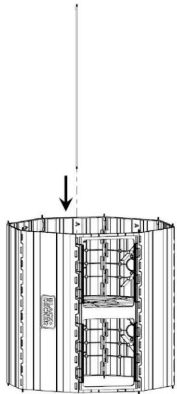
Technical line drawing of a mechanical device with internal components and a central hub (no text or symbols)Step 13. Insert the shaft through the hole in the center of the side covers.
Completed barrel
Section 2: Assemble the Base
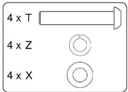
Step 14. Lay out components.
See picture to ensure side supports and support legs are oriented properly.
natural_image
Simple line drawing of a vertical metal bracket with a circular frame (no text or symbols)Ensure lip of side support faces outward
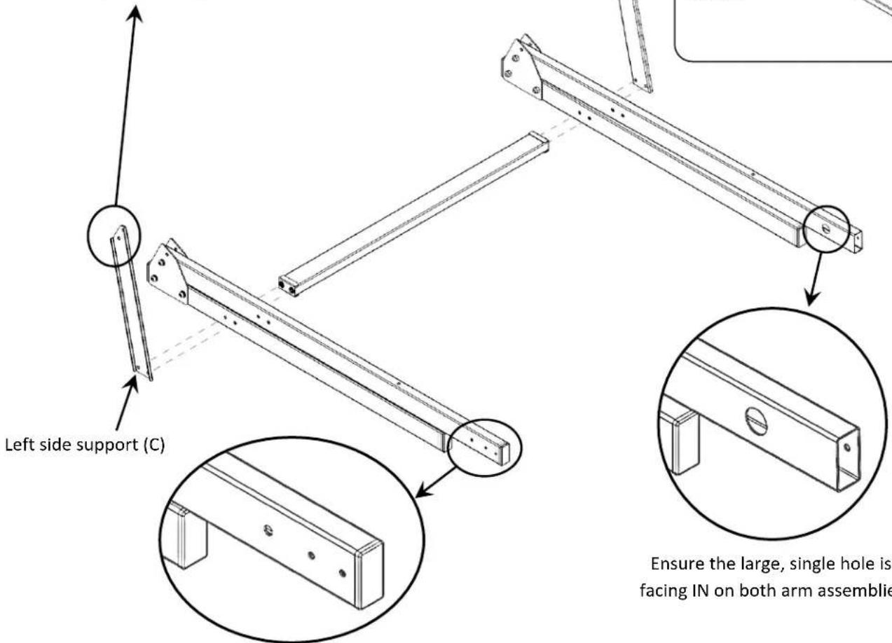
Ensure the 3 smaller holes are facing OUT on both arm assemblies
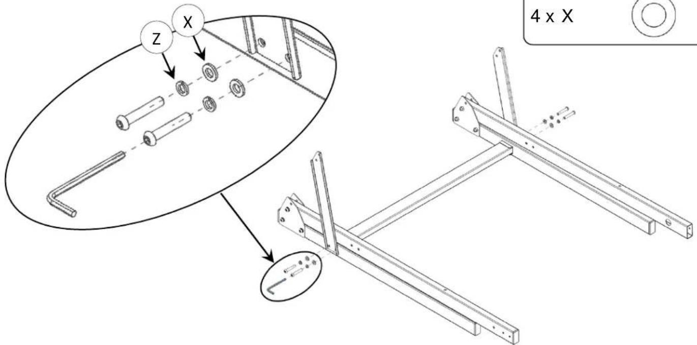
Step 15. Install the fasteners in the order shown using a 4 mm hex key. DO NOT FULLY TIGHTEN.
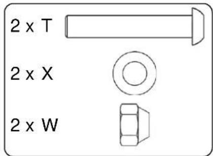
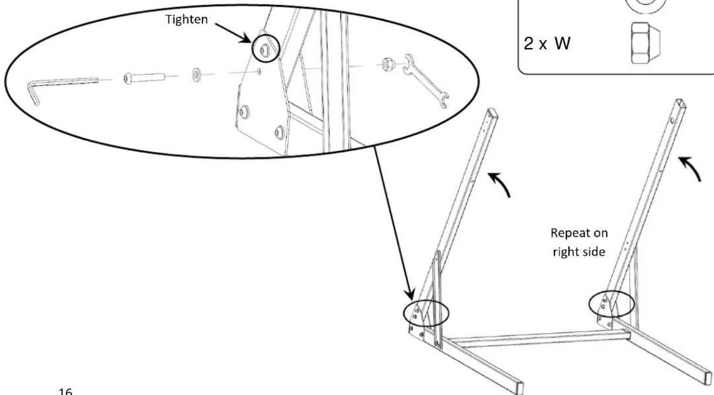
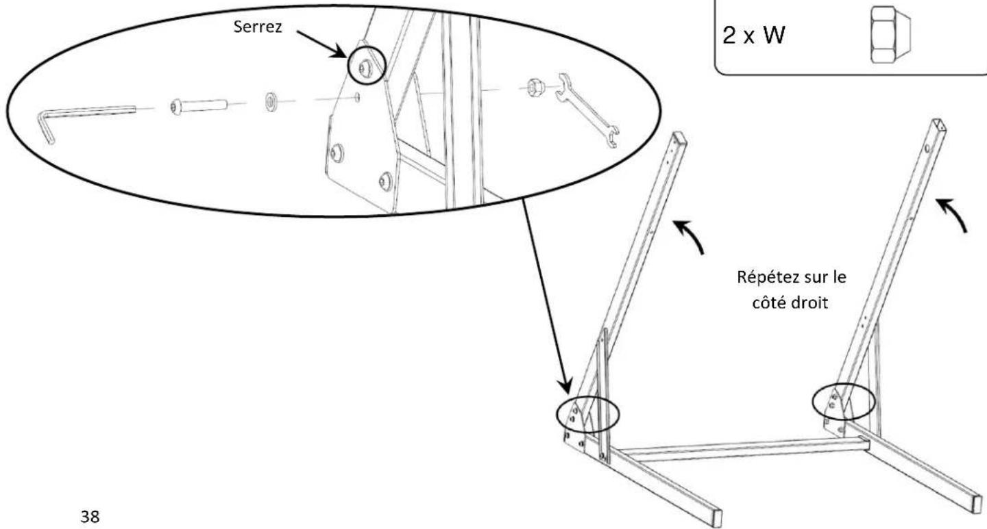
Step 16. Rotate the top legs up and install the fasteners. Tighten with a 4 mm hex key and 10 mm wrench simultaneously, then tighten the screw above it (see picture) with the same tools.
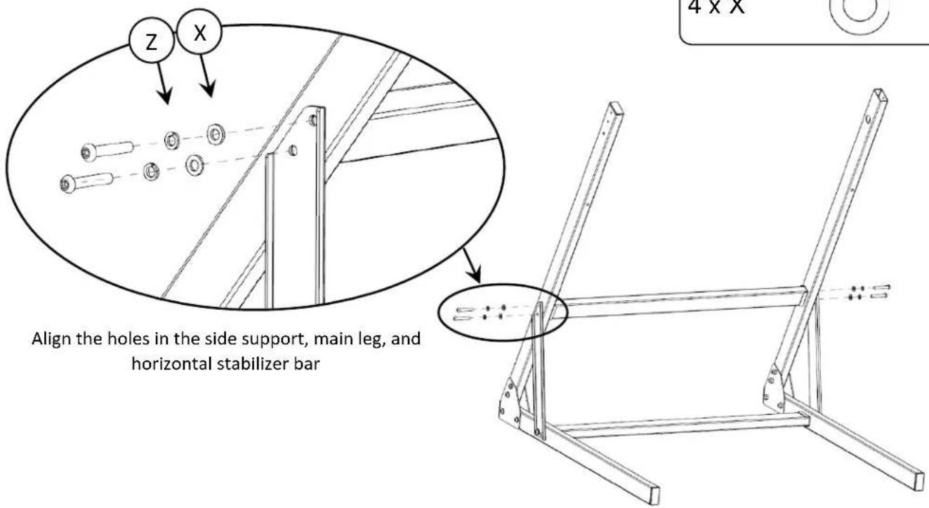
Step 17. Place a horizontal stabilizer bar between the top support legs and install the fasteners in the order shown. DO NOT FULLY TIGHTEN.
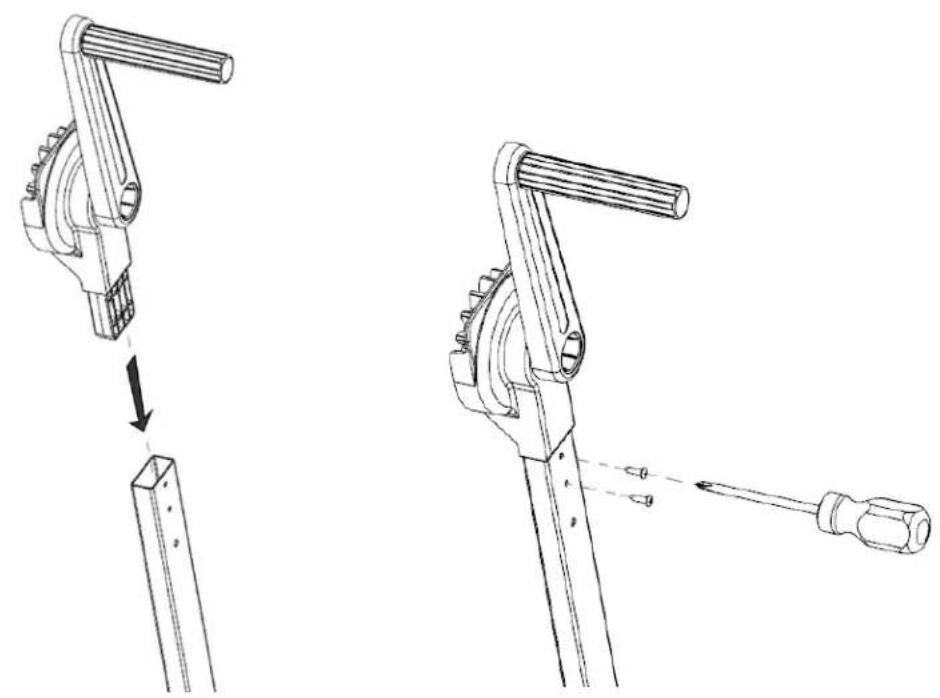
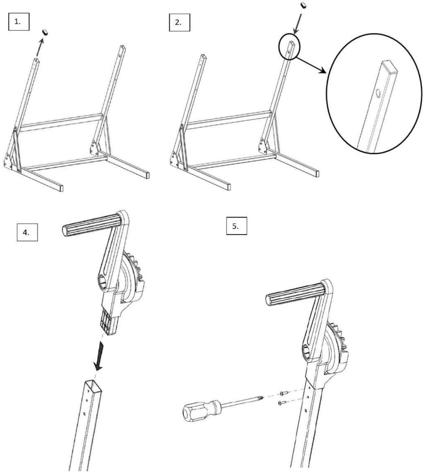
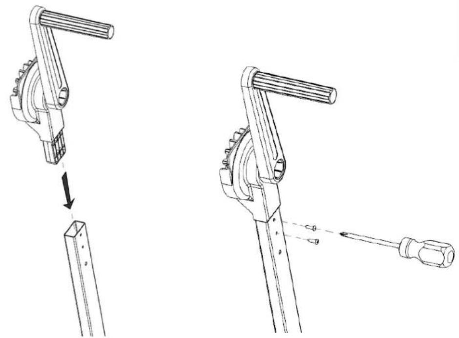
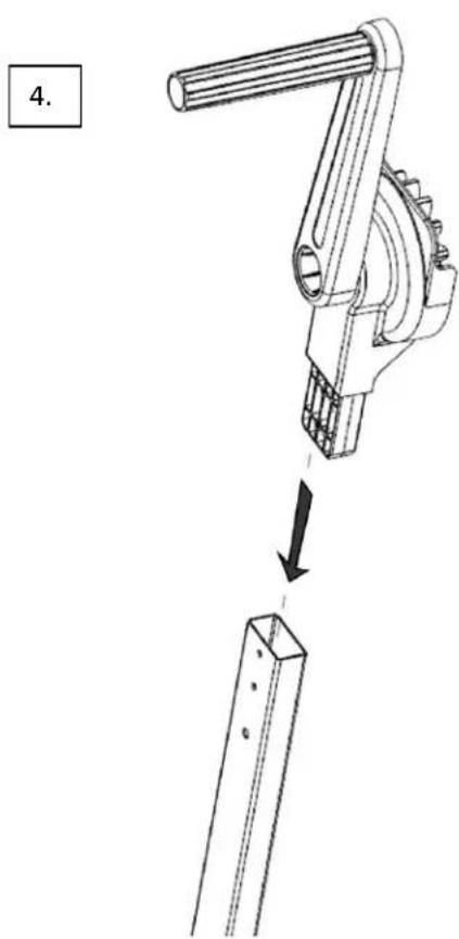
Step 18. Install the handle on the main leg. Tighten fasteners with a cross head screwdriver. NOTE: Handle can be installed on left support arm for left-handed operation. See Step 19 for details.
natural_image
Technical line drawing of a mechanical lever mechanism showing two stages: press release and tool insertion (no text or symbols)Step 19. To install the handle on the left support arm, remove the end cap on the top of the left arm and install it on the right arm.
Then follow Step 18 to install the handle on the left arm, ensuring that the handle faces outwards and the gear faces inwards.
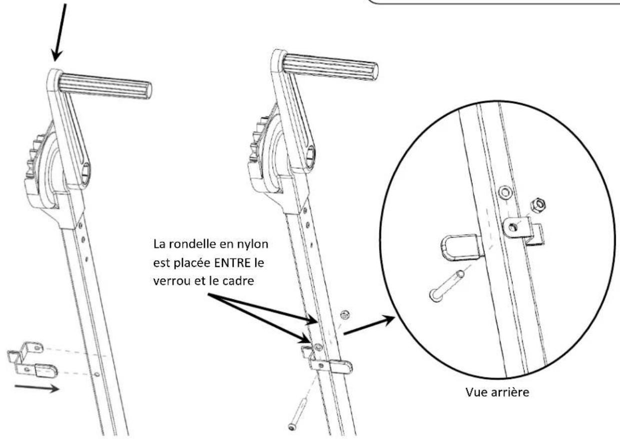
Step 20. Install the rotation lock on the same side as the handle. Tighten hardware with 10 mm wrench and 4 mm hex key until the lock securely stays in place when rotated up and down. If lock is too loose, it may disengage unexpectedly.
Handle and lock are on the same side.
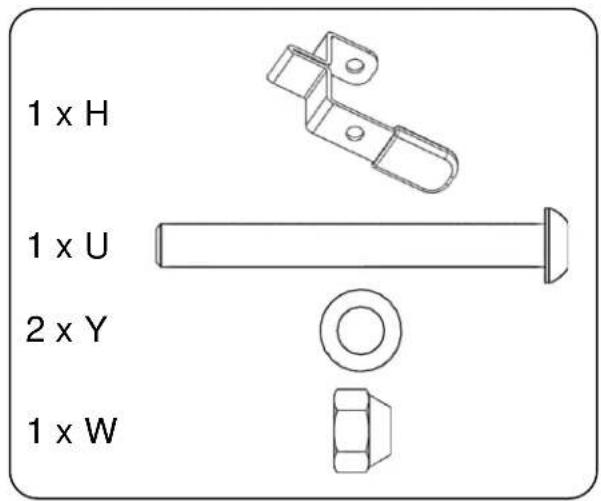
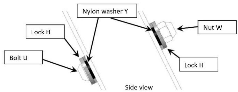
flowchart
graph TD
    A["Nylon washer Y"] --> B["Side view"]
    C["Bolt U"] --> B
    D["Nut W"] --> B
    E["Lock H"] --> B
    F["Lock H"] --> B
    style A fill:#f9f,stroke:#333
    style C fill:#f9f,stroke:#333
    style D fill:#f9f,stroke:#333
    style E fill:#f9f,stroke:#333
    style F fill:#f9f,stroke:#333
    style B fill:#ccf,stroke:#333
    style C fill:#ccf,stroke:#333
    style D fill:#ccf,stroke:#333
    style E fill:#ccf,stroke:#333
    style F fill:#ccf,stroke:#333
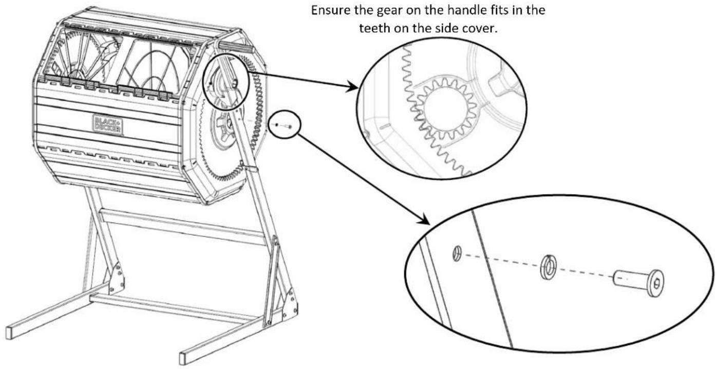
Section 3: Install the Composter Barrel on the Base
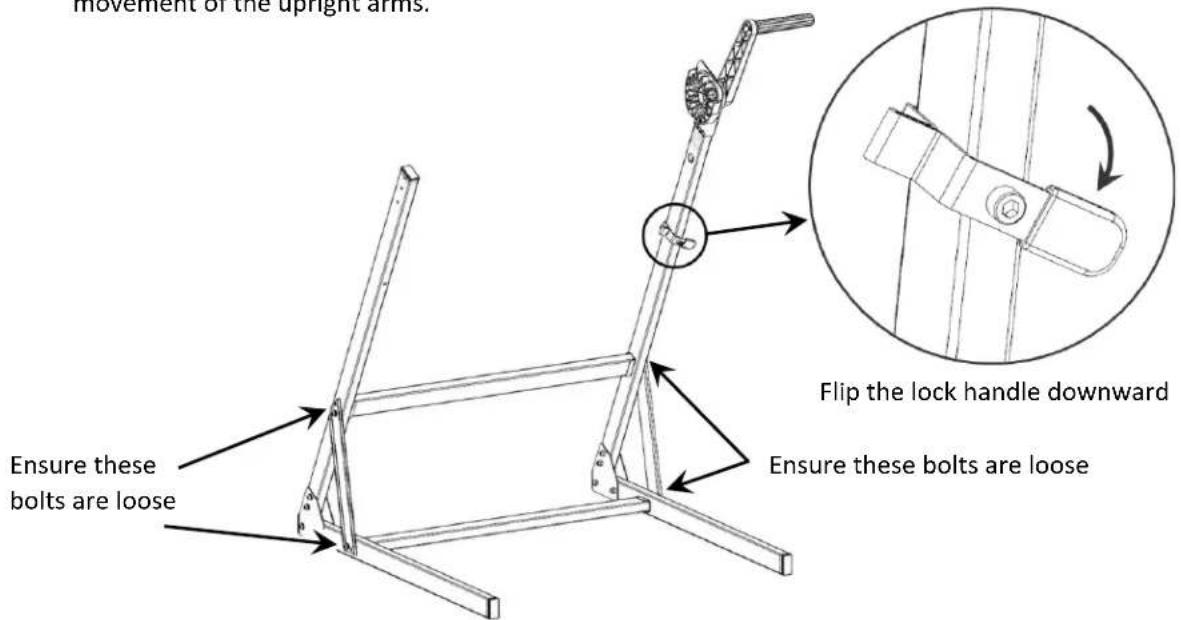
Step 21. Two people are needed for this stage of the assembly. Flip the lock handle downwards, and ensure the indicated bolts are loose to allow for movement of the upright arms.
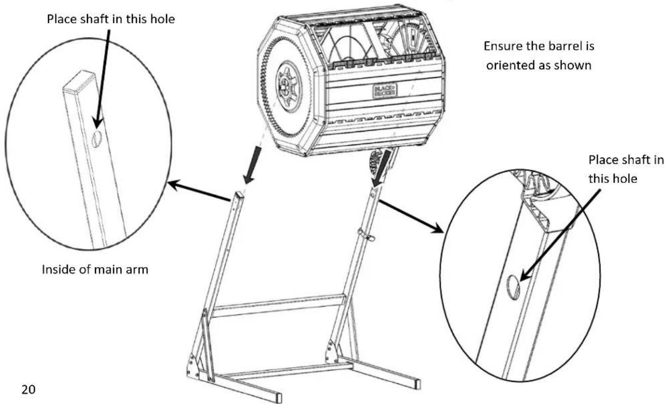
Step 22. For this step, one person should hold the barrel, and the second person should help guide the shaft into the base. Place the barrel in the base, guiding the shaft into the holes on the inside of the base arms. Gently pull the arms outwards to fit the shaft. Ensure the handle does not block the side of the door base panel.
Step 23. Secure the shaft in place through the frame with the hardware as shown. Tighten with a 4 mm hex key.
Step 24. Install fasteners on the remaining side. Tighten with a 4 mm hex key.
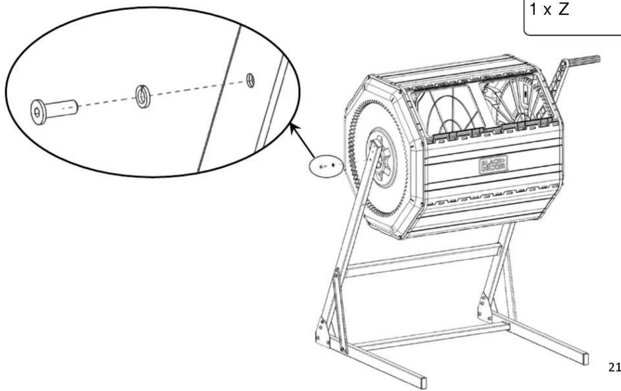
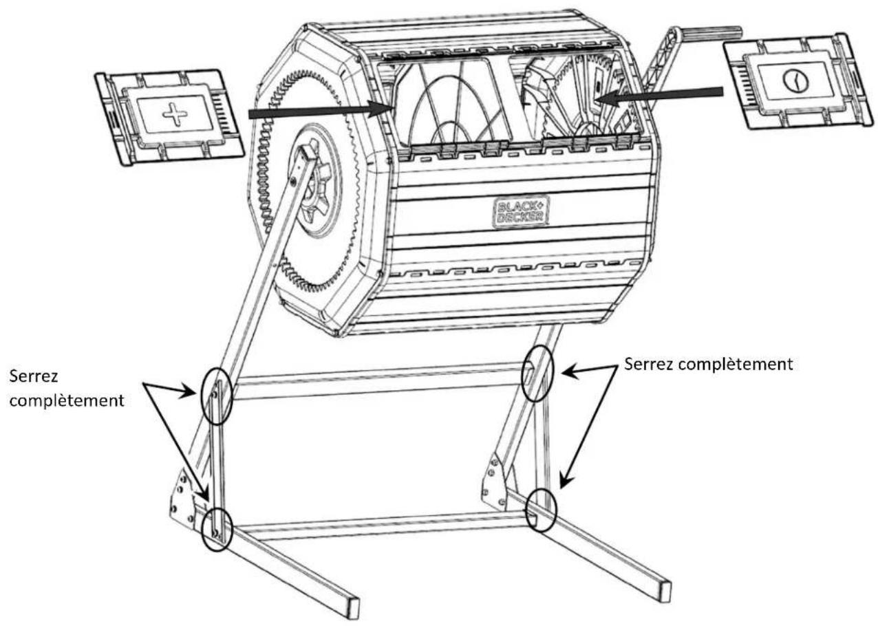
Step 25. Slide each door onto the door base panel. Tighten the loose hardware with a 4 mm hex key.
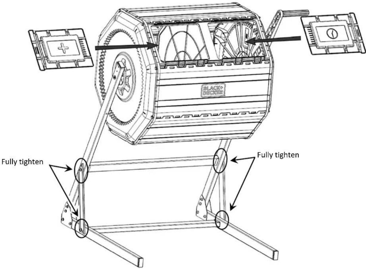
Step 26. Assembly is complete!
Features
natural_image
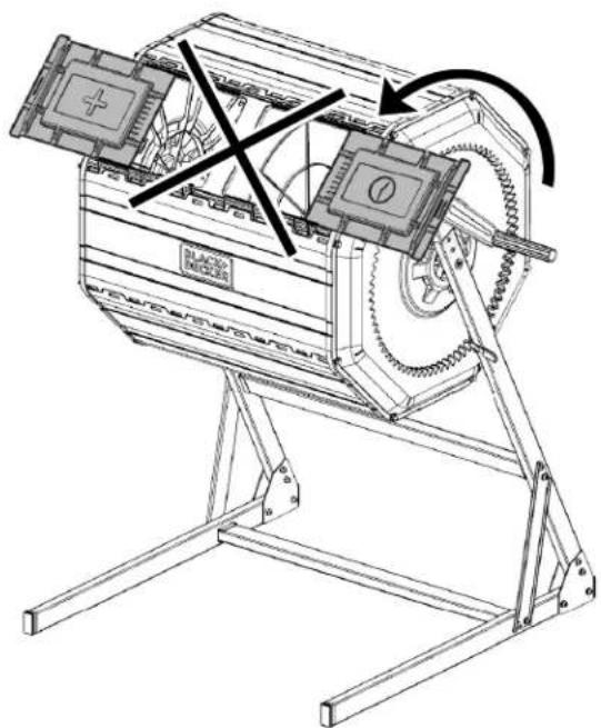
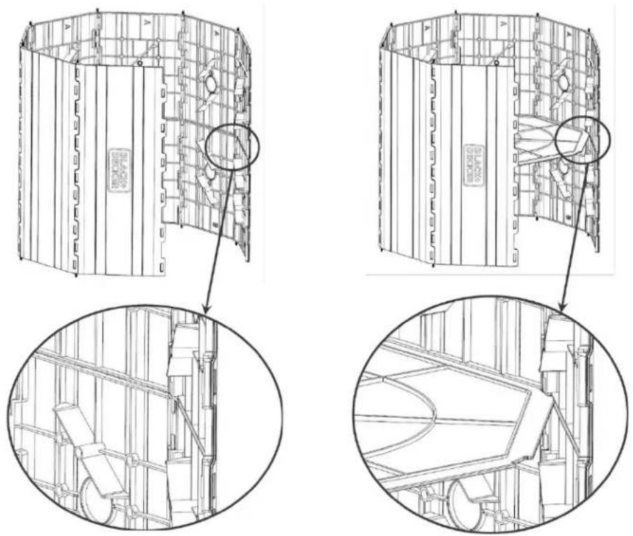
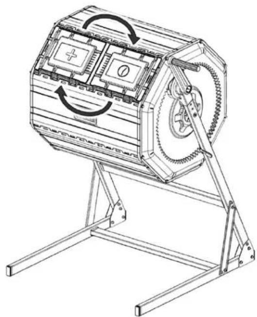
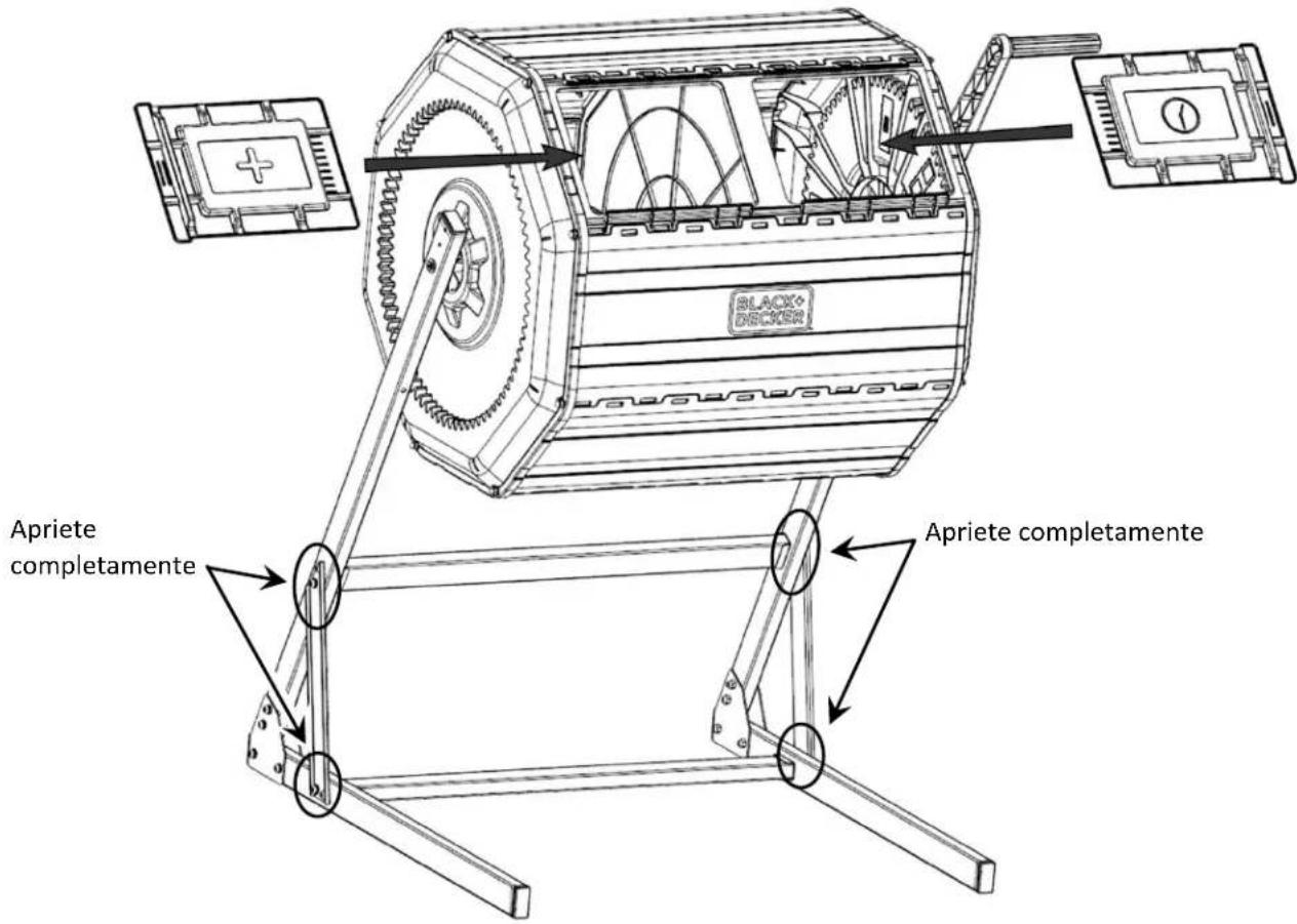
Technical line drawing of a mechanical device with rotating gears and mounting base (no text or symbols)Doors can switch sides.
When ‘ + ’ side is full, swap doors. Add new materials to ‘ + ’ side, give ‘ ⓣ ’ side time to compost.
flowchart
graph TD
    A["Rotated Wheel with Radial Cut"] --> B["Rotated Gear Component"]
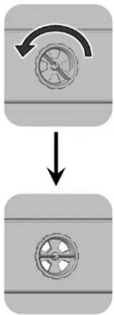
Rotate air vents open or closed to regulate moisture
natural_image
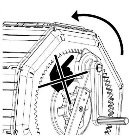
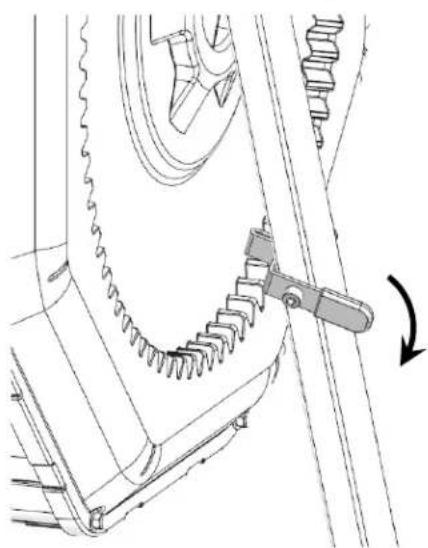
Mechanical gear assembly diagram showing meshing gears and a lever mechanism (no text or labels)Rotation lock disengaged; barrel can spin

natural_image
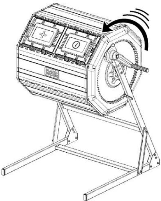
Mechanical gear assembly diagram showing meshing gears and a rotating shaft (no text or labels)Rotation lock engaged; barrel cannot spin
Handle and rotation lock can be installed on the opposite support arm for left-handed operation
About Composting
What to Compost
Browns:
- Hay and straw
- Dead leaves
- Sawdust
- Shredded black and white newspaper
- Hair and fur (no chemicals or dyes)
- Non-glossy paper and envelopes
- Cardboard
- Shredded 100% cotton materials
- Dust Bunnies
Greens:
- Fruit and vegetable scraps
- Coffee grounds
- Grass clippings
- Eggshells
- Tea leaves and tea bags
- Stale bread
- Cooked pasta and rice
How to Compost ^1
- Select your food scraps.
- Store the food scraps in your BLACK+DECKER Countertop Compost Bin.
- Choose a place in your yard for your BLACK+DECKER Tumbler Composter
- Make the compost mix - "Green and Browns" - layer greens and browns starting with the browns to allow for aeration. The number of layers depends on your space and amount of food scraps. Keep the layers to an inch or two. You can put a little bit of browns on the top to keep away flies and odors. (Remember 2:1 brown to green ration). Turn the compost to mix thoroughly.
- Maintain the compost - Check that the compost is slightly damp and add water when needed. Turn the compost 5-10 rotations at least 2-3 times a week.
- Removing the compost - the compost is done when it's dark and crumbly with an earthy smell. Empty the composter into a bucket, wheelbarrow, or tarp, and use in your garden.
What NOT to Compost
- Human or pet waste
- Meats and dairies
- Fats, grease, lard, or oils
- Plastics
- Coal or charcoal ashes
- Chemically treated materials
- Diseased or invasive plants
- Bones
- Black walnut tree leaves or twigs
- Yard trimmings treated with chemical pesticides
For more information on what you can and cannot compost, visit the EPA's website: https://www.epa.gov/recycle/composting-home
Looking for more information on composting or BLACK+DECKER®'s line of composting products? Scan below.

natural_image
Technical line drawing of a mechanical device with no visible text or symbols
natural_image
Technical line drawing of a mechanical gear assembly with no visible text or symbolsnatural_image
Technical line drawing of a mechanical device with rotating gears and a base mount (no text or symbols)
natural_image
Technical line drawing of a mechanical device with no visible text or symbols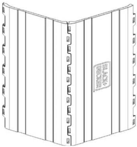
natural_image
Line drawing of a closed book with visible spine, spines, and cover (no text or symbols)natural_image
Technical diagram of two mechanical components labeled A and B, showing internal connections and grid patterns (no text or symbols beyond labels)Dessous du panneau
natural_image
Architectural wireframe diagram of a curved structural frame with directional arrows indicating rotation (no text or symbols)
natural_image
Architectural diagram of a multi-level building structure with circular grid layout and central arrow (no text or symbols)natural_image
Technical line drawing of a hexagonal building interior with circular ceiling and window (no text or symbols)natural_image
Technical line drawings of industrial equipment components, showing cross-sectional and top views with no visible text or symbols.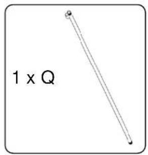
natural_image
Technical line drawing of a hexagonal mechanical component with internal gear-like structure (no text or symbols)natural_image
Technical line drawing of a mechanical device with gear and housing, showing internal components and a close-up inset (no text or symbols)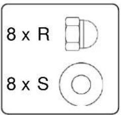
natural_image
Technical line drawing of a mechanical component with a central hub and surrounding grooves (no text or symbols)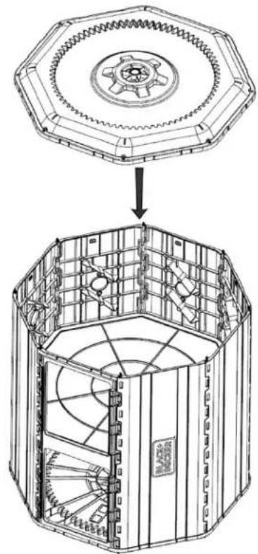
natural_image
Technical line drawing of a mechanical device with gear and internal components, showing a close-up view of a wrench tool (no text or symbols present)natural_image
Technical line drawing of a hexagonal mechanical device with internal components (no text or symbols)Section 2: Assembler la Base
natural_image
Technical line drawing of a mechanical device with rotating gears and mounting base (no text or symbols)flowchart
graph TD
    A["Top: Wheel with 200-degree rotation arrow"] --> B["Bottom: Wheel with 400-degree rotation arrow"]
natural_image
Mechanical gear assembly diagram showing teeth and chain alignment (no text or symbols)natural_image
Mechanical gear assembly diagram showing meshing gears and a rotating shaft (no text or labels)natural_image
Technical line drawing of a mechanical device with no visible text or symbols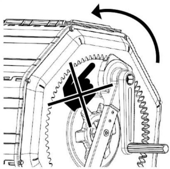
natural_image
Technical line drawing of a mechanical device with gears and a central gear mechanism (no text or symbols)natural_image
Technical line drawing of a mechanical device with rotating gears and a base mount (no text or symbols)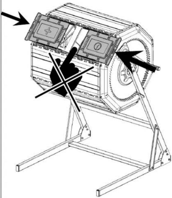
natural_image
Technical line drawing of a mechanical device with no visible text or symbols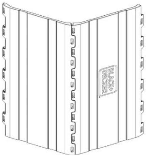
natural_image
Line drawing of a closed book with vertical spine and decorative side panels (no text or symbols)natural_image
Technical diagram of two mechanical components labeled A and B, showing internal structural elements and connection points (no text or symbols beyond labels)Lado inferior de panel

natural_image
Architectural wireframe diagram of a curved structural frame with directional arrows indicating rotation (no text or symbols)
natural_image
Architectural diagram of a multi-level building structure with circular grid layout and an upward arrow indicating direction (no text or symbols)natural_image
Technical line drawing of a hexagonal octagonal structure with internal compartments and directional arrows indicating rotation (no text or symbols)natural_image
Technical line drawings of industrial equipment components, showing cross-sectional views with no visible text or symbols.natural_image
Technical line drawing of a cylindrical mechanical or architectural component with internal structural details and a vertical arrow indicating direction (no text or symbols present)

natural_image
Technical line drawing of a hexagonal mechanical component with internal gear-like structure (no text or symbols)natural_image
Technical line drawing of a mechanical device with gear and mounting holes, shown in two views (no text or symbols)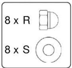

natural_image
Technical line drawing of a mechanical component with a central hub and surrounding grooves (no text or symbols)
natural_image
Technical line drawing of a mechanical device with gear and internal components, showing exploded view (no text or symbols)natural_image
Technical line drawing of a mechanical device with internal components and a central hub (no text or symbols)natural_image
Technical line drawing of a mechanical bracket with a circular outline (no text or symbols)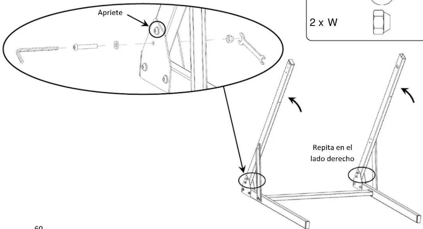
natural_image
Technical line drawing of a mechanical lever mechanism showing two stages: press release and disassembly (no text or symbols present)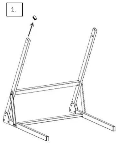
natural_image
Technical line drawing of a metal frame structure with supports and a pull pointer (no text or symbols)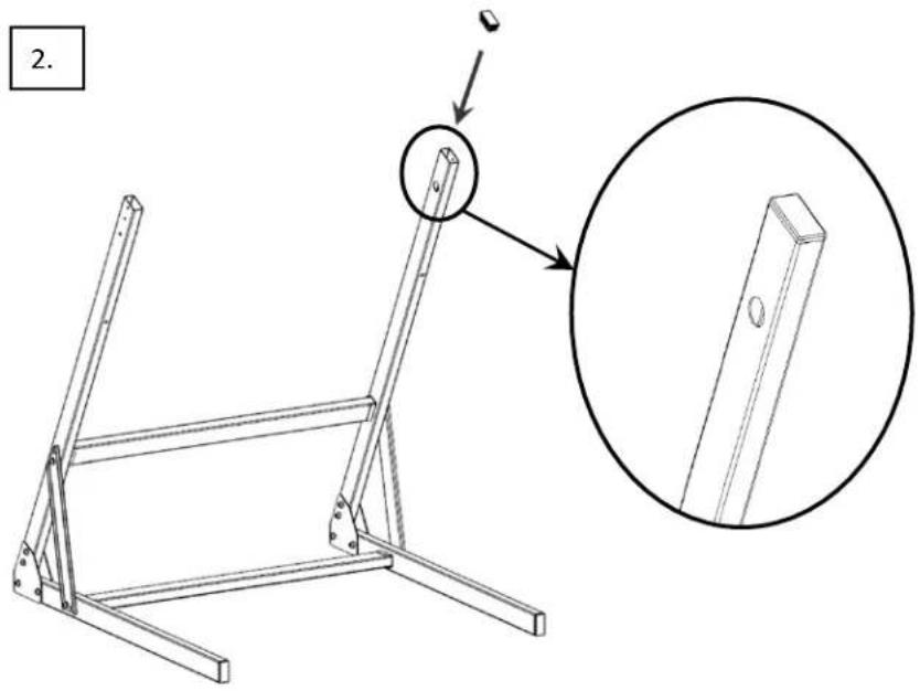
natural_image
Mechanical assembly diagram showing a robotic arm with a base and shaft, no text or symbols present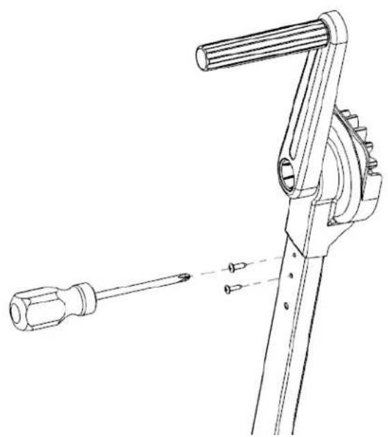
natural_image
Technical line drawing of a mechanical tool with a screwdriver and lever mechanism (no text or symbols)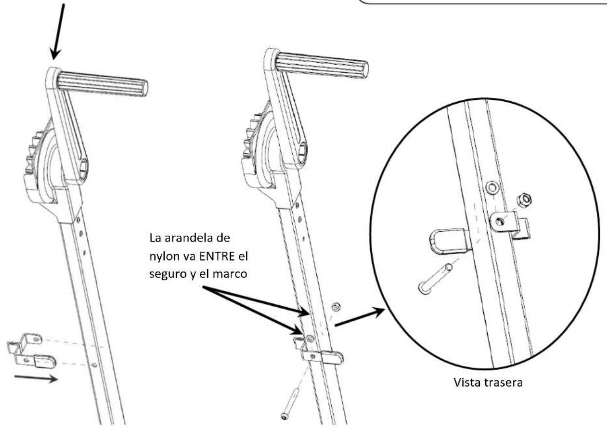
natural_image
Technical line drawing of a mechanical device with rotating components and mounting base (no text or symbols)flowchart
graph TD
    A["Wheel with 4 wheels"] --> B["Rotated Wheel with 4 wheels"]
    style A fill:#f9f,stroke:#333
    style B fill:#bbf,stroke:#333
natural_image
Technical line drawing of a mechanical gear assembly with a rotating tool (no text or symbols)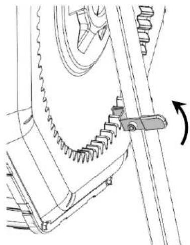
natural_image
Mechanical assembly diagram showing gear and shaft components (no text or labels)


- Table of Contents | Table des Matières | Tabla de Contenido
- INSTRUCTION MANUAL....3
- Intended Use
- Definitions: Safety Alert Symbols and Words
- Composting Safety Warnings
- Additional Safety Information
- MAINTENANCE
- Cleaning
- Accessories
- Repairs
- Register Online
- TWO-YEAR LIMITED WARRANTY
- WARNING
- Assembly Instructions
- Materials
- Section 1: Assemble the Composter Barrel
- Section 2: Assemble the Base
- Section 3: Install the Composter Barrel on the Base
- Features
- About Composting
- What to Compost
- Browns:
- Greens:
- How to Compost 1
- What NOT to Compost
- Section 2: Assembler la Base
Brand : BLACK & DECKER
Model : BDSTGA9701
Category : Rice cooker