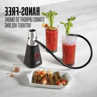
41-0801-W - Slow cooker Weston - Free user manual and instructions
Find the device manual for free 41-0801-W Weston in PDF.


| Product Type | Smoke infuser for food and beverages |
| Brand | Weston |
| Model | 41-0801-W |
| Power Source | 4 AA batteries (not included) |
| Main Functions | Cold smoking, smoke infusion for meats, cheeses, fish, fruits, vegetables, desserts, and beverages |
| Material | Stainless steel (grates), plastic (base) |
| Capacity | Compatible with dome or plastic bag |
| Cleaning | Hand wash removable parts (do not put in dishwasher); do not immerse base |
| Safety | Hot surface; do not use unattended; keep out of reach of children; do not use near flammable materials |
| Spare Parts | Grates, compartments, hose, smoke nozzle, chip holder |
| Warranty | 1 year against defects in material and workmanship |
| Customer Service | 1-800-814-4895 (USA) or 001-216-901-6801 (outside USA) |
| Compatibility | Uses food-grade wood chips (apple, cherry, mesquite, etc.) |
Frequently Asked Questions - 41-0801-W Weston
User questions about 41-0801-W Weston
0 question about this device. Answer the ones you know or ask your own.
Ask a new question about this device
Download the instructions for your Slow cooker in PDF format for free! Find your manual 41-0801-W - Weston and take your electronic device back in hand. On this page are published all the documents necessary for the use of your device. 41-0801-W by Weston.
USER MANUAL 41-0801-W Weston
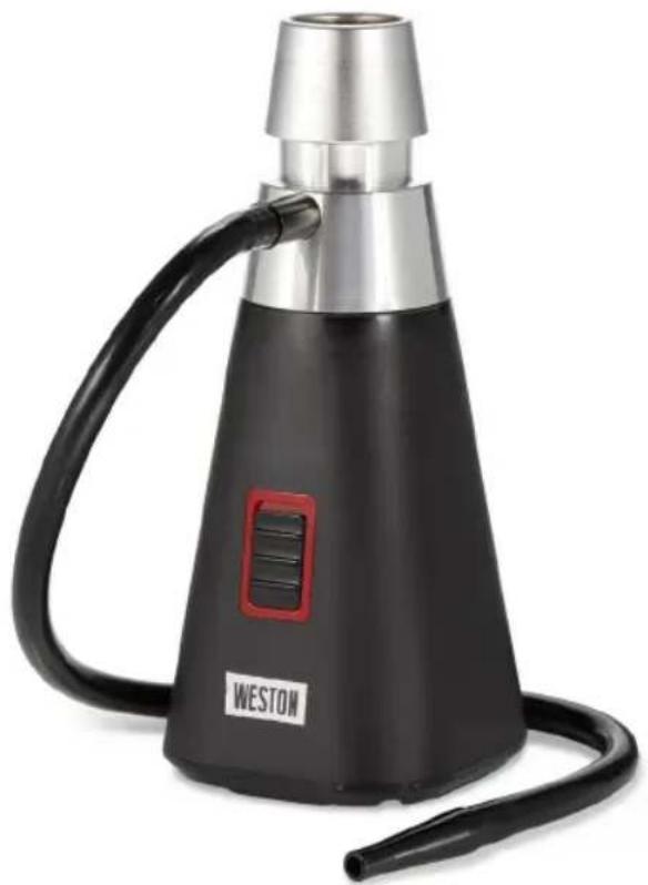
SR01
SMOKE INFUSER
INFUSEUR DE FUMÉE
INFUSOR DE HUMO
41-0801-W
IMPORTANT SAFEGUARDS
When using this infuser, basic safety precautions should always be followed to reduce the risk of fire, and/or injury to persons, including the following:
- Read all instructions.
- This infuser is not intended for use by persons with reduced physical, sensory, or mental capabilities, or lack of experience and knowledge, unless they are closely supervised and instructed concerning use of the appliance by a person responsible for their safety.
- This infuser shall not be used by children. Keep the appliance out of reach of children.
- Close supervision is necessary when the infuser is used near children. Children should be supervised to ensure that they do not play with the infuser.
- Do not operate in the presence of explosives and/or flammable fumes or liquids.
- Do not store outdoors.
- Place the infuser only on a dry, level, and nonflammable surface.
- Do not place on or near a hot gas or electric burner or in a heated oven.
- A fire may occur if the infuser is covered or touching flammable material, including curtains, draperies, walls, overhead cabinets, paper or plastic products, cloth towels, and the like, when in operation.
- Do not use infuser for other than smoking food items.
- Do not operate unattended.
- Only apply enough flame to the chips to create a smolder and generate the smoke for the desired use.
-
Only use food-grade chips that are suitable for smoke infusing.
-
Never operate the infuser without the stainless steel mesh screens in place; burning/glowing embers may enter the base, damaging the unit, or be ejected through the nozzle, creating a fire or burn hazard.
- Always use a match or lighter to ignite the materials in the infuser; DO NOT USE a kitchen torch or other heat device, as the excessive heat may damage the unit.
- Always empty ash and burnt material into a nonflammable receptacle.
- Do not point the infuser at any person or flammable object.
- Avoid using the infuser in areas where smoke may activate smoke alarms or fire suppression systems.
- The base and chip chamber of the infuser will become very hot when in use. Allow device to cool completely before touching the base or chip chamber, cleaning, or storing.
- Do not operate after the infuser malfunctions or has been dropped or damaged in any manner. Repairs must be conducted by the manufacturer, its service agent, or similarly qualified persons in order to avoid a hazard. Contact Customer Service for information on examination, repair, or adjustment as set forth in the Limited Warranty.
- Do not incinerate this appliance even if it is severely damaged. The batteries can explode in a fire.
SAVE THESE INSTRUCTIONS
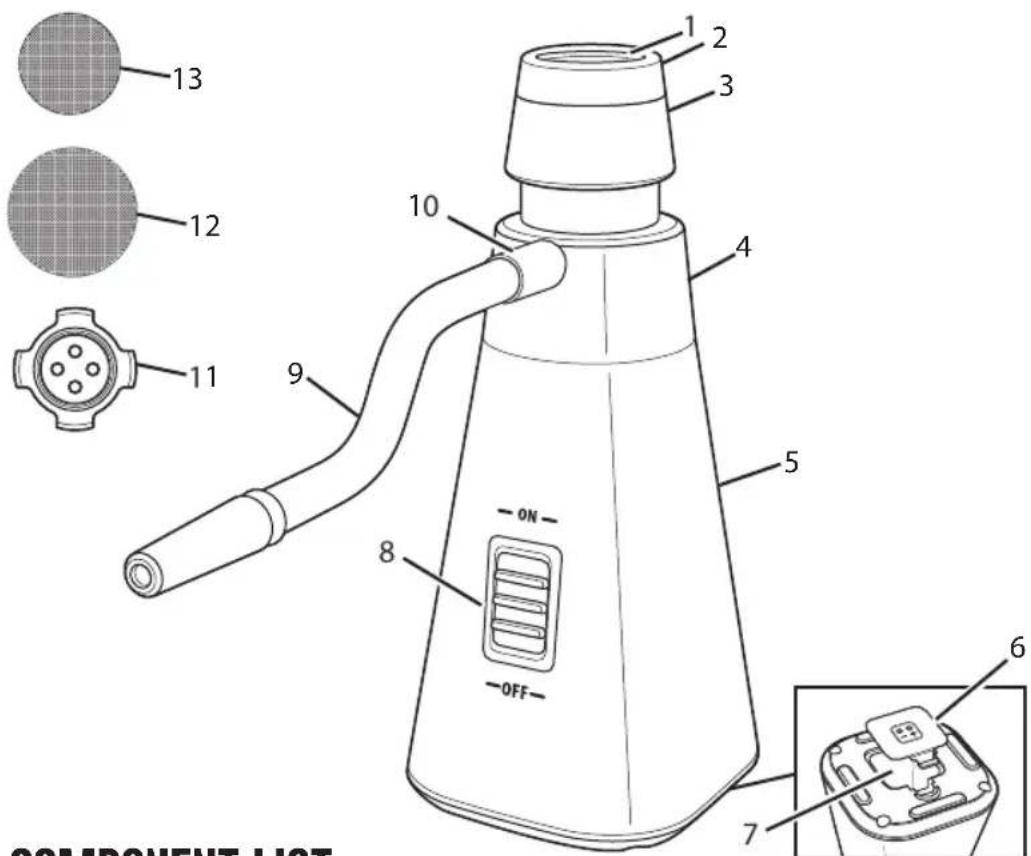
Bottom of Base
COMPONENT LIST
| DIAGRAM NUMBER PART DESCRIPTION | |
| 1 METAL HONEYCOMB SCREEN | |
| 2 REMOVABLE CHAMBER CAP | |
| 3 REMOVABLE CHIP CHAMBER (HOLDS CHIP STAND AND LARGE MESH SCREEN) | |
| 4 SMOKE CHAMBER (HOLDS SMALL MESH SCREEN) | |
| 5 BASE (WITH FAN AND MOTOR) | |
| 6 BATTERY COMPARTMENT COVER WITH CLIP | |
| 7 BATTERY COMPARTMENT (HOLDS 4 AA BATTERIES, NOT INCLUDED) | |
| 8 ON/OFF SWITCH | |
| 9 REMOVABLE HOSE WITH PULL-OFF METAL TIP | |
| 10 REMOVABLE SMOKE OUTLET | |
| 11 CHIP STAND (INSIDE CHIP CHAMBER) | |
| 12 LARGE MESH SCREEN (INSIDE CHIP CHAMBER) | |
| 13 | SMALL MESH SCREEN (INSIDE SMOKE CHAMBER) |
If any components of this unit are broken, the unit does not operate properly or you need a replacement instruction manual, visit us on the web at WestonBrands.com.
Or call Weston Brands, LLC toll free at 1-800-814-4895
Monday thru Friday 8:00am-5:00pm ET. Outside the U.S. call 001-216-901-6801
BEFORE FIRST USE
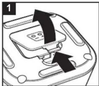
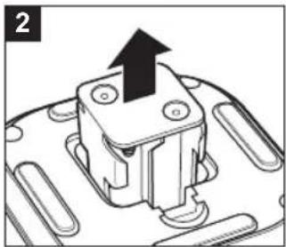
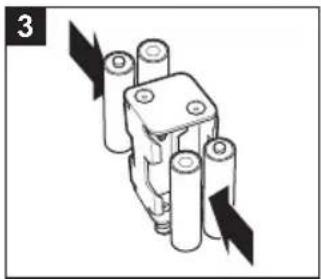
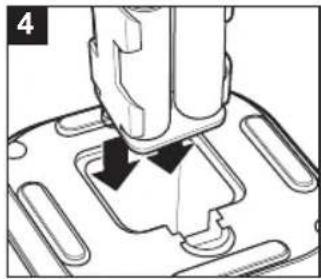
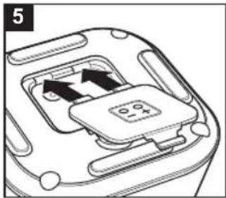
4
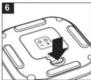
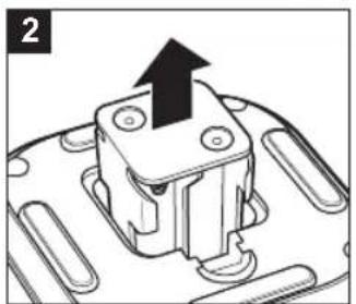
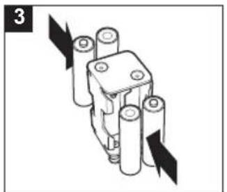
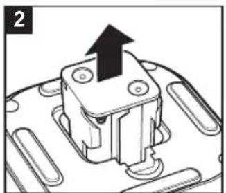
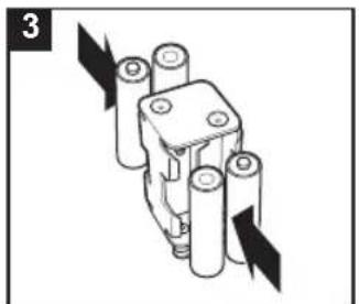
- Remove Battery Compartment Cover by pushing Clip towards Battery Compartment. Lift up Cover.
- Pull out Battery Holder.
- Load batteries according to + and - diagram inside Holder.
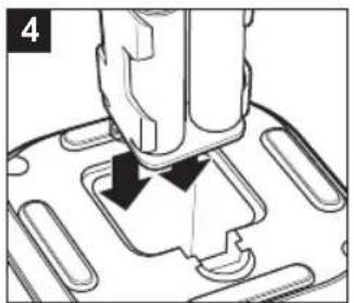
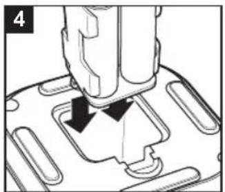
- Insert Battery Holder with spring coil side down, aligning spring coils with metal connect points inside Battery Compartment.
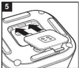
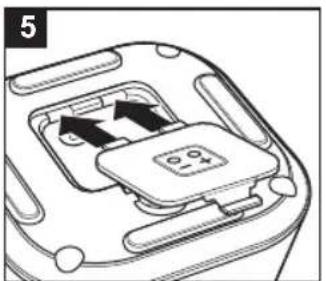
- Insert tabs of Battery Compartment Cover into slots on bottom of Base.
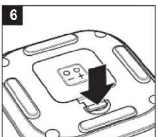
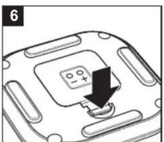
- Snap Clip into place.
HOW TO USE
Smoke Infusers are used for smoking foods, such as sliced deli meats, cheeses, fish, fruits, vegetables, desserts, and drinks.
NOTE: Screens are removable for easy cleaning. Use caution when assembling or disassembling to not lose them.
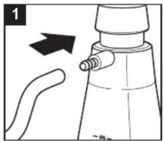
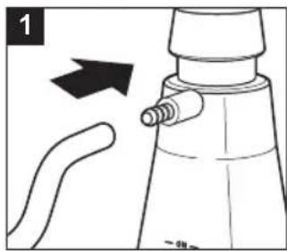
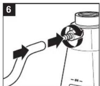
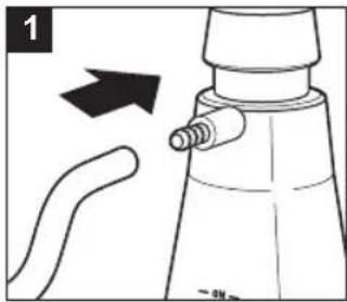
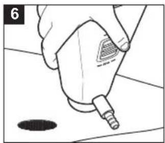
- Push rubber end of Hose onto Smoke Outlet. Make sure Hose is secure.
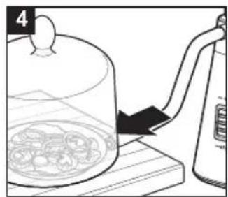
- Place food to be smoked on a cutting board and cover with a cloche*.
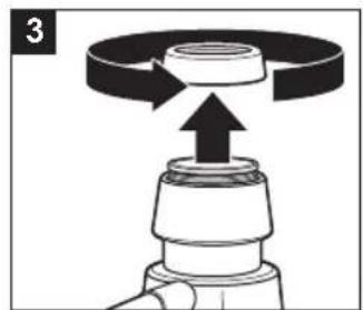
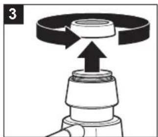
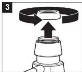
- Turn Chamber Cap counterclockwise to remove and fill Chip Chamber with wood chips. Add Chamber Cap and turn clockwise to tighten.
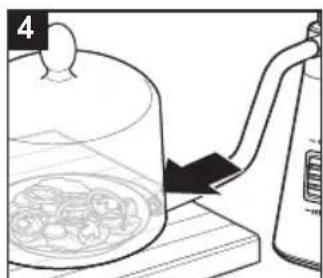
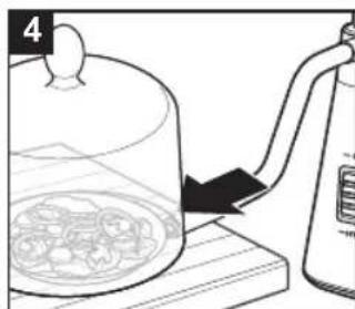
- Insert tip of Hose into opening of cloche.
- Place Smoke Infuser on level surface.
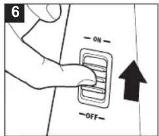
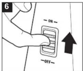
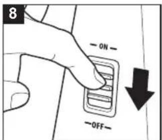
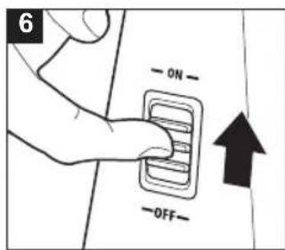
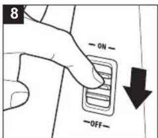
- Move ON/OFF Switch up to turn ON (I).
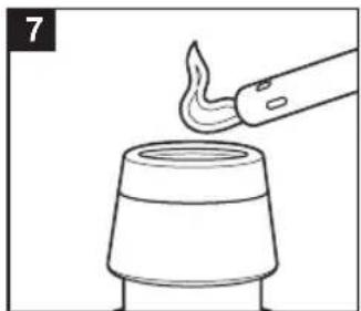
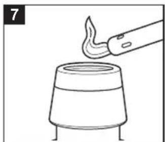
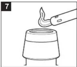
- Place a multi-purpose lighter on Metal Honeycomb Screen of Chamber Cap and light it to set wood chips on fire. Smoke will automatically start coming from Hose.
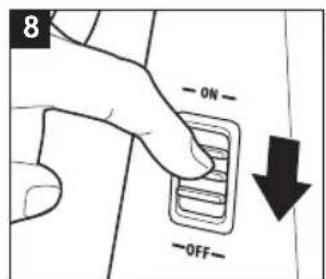
- Switch to OFF Ⓐ) as soon as smoke starts filling cloche or container.

CAUTION: HOT SURFACE. The chip chamber and chamber cap get hot. Allow to cool before contacting.
- Keep food under cloche for 30 seconds to one minute or until desired smoke level is reached.
- Tilt cloche away from you when removing.
- Let Smoke Infuser cool completely.
- Smoke Infuser must be taken apart and cleaned after every use.
TIPS:
- Allowing some foods like cheese and sliced meats to refrigerate after smoking mellows flavor.
- To determine level of smokiness start out with 30 seconds and add more time if more flavor is desired.
- When selecting wood chips and foods to smoke, apple and cherry wood chips have a milder flavor and mesquite a stronger flavor.
* A cloche is a glass dome placed over foods or beverages that will be smoked. Some clothes have a small opening to slide the Smoke Infuser Hose through; or the Hose can be placed at the bottom of the cloche, pointing to the center.
If you don't have a cloche, you can use a zipper-lock, food-safe plastic bag: unzip top of bag enough to point the hose into the bag, and seal around the hose. Or you can use a bowl or container and cover with plastic wrap: lift the plastic wrap to insert hose and use the plastic wrap to seal the opening around the Smoke Infuser Hose.

CARE AND CLEANING
6
- Make sure Smoke Infuser is turned OFF (O) and wood chips have cooled completely.
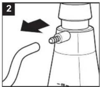
- Pull Hose from Smoke Outlet. Set aside.
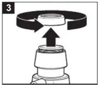
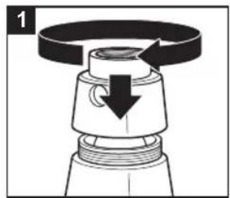
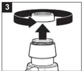
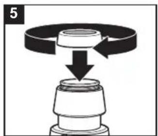
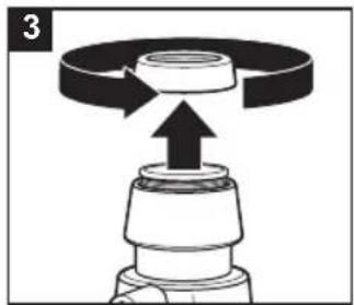
- Turn Chamber Cap counterclockwise to remove. Set aside.
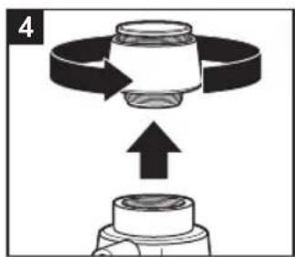
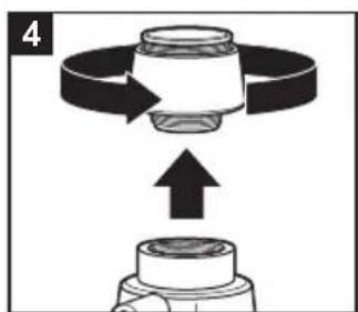
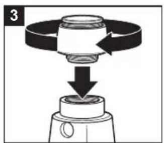
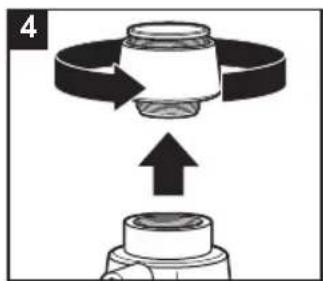
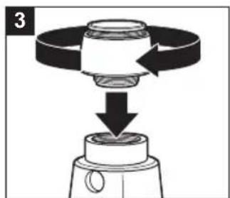
- Place paper towels on countertop. Turn Chip Chamber counterclockwise to remove.
- Turn Chip Chamber upside down on paper towel. Place handle end of a small spatula through bottom opening to remove Large Mesh Screen, Chip Stand, and any remaining wood chips.
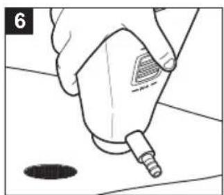
- Turn Base upside down on same paper towel to remove Small Mesh Screen.
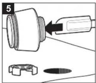
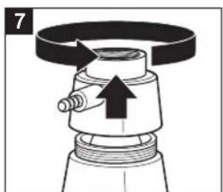
- Turn Smoke Chamber counterclockwise to remove. Pull Fan straight up and wipe top of Base with a damp cloth to remove any oils and buildup. Let top of Base dry completely.
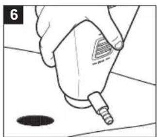
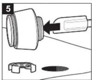
- Turn Removable Smoke Outlet counterclockwise to remove and set aside.
- Wash Hose, Metal Honeycomb Screen, Mesh Screens, Chip Chamber, Chip Stand, Chamber Cap, Smoke Chamber, and Smoke Outlet in hot, soapy water. Rinse and dry completely before assembling. Do not place any parts of Smoke Infuser in dishwasher.
NOTES:
- Do not immerse Base in water for cleaning.
- If Smoke Infuser will not be used for awhile, remove batteries, disassemble, clean, and dry completely before storing.
- Screens and parts are very small. Be sure to place them in a secure area to make sure parts will not be thrown away.
To Assemble After Cleaning:
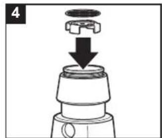
- Push Fan onto Motor on top of Base. Place Smoke Chamber over fan and turn clockwise to screw into place.
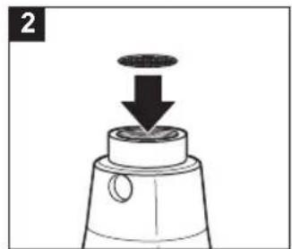
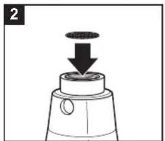
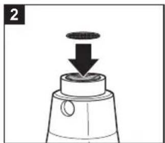
- Place Small Mesh Screen in opening of Smoke Chamber.
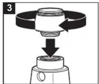
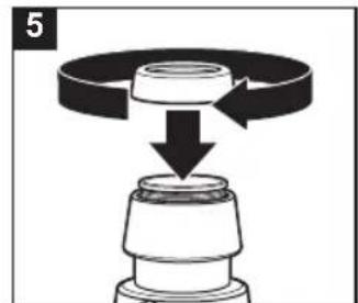
- Place Chip Chamber on top of Base and turn clockwise to secure in place.
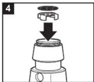
- Add Chip Stand to Chip Chamber; then place Large Mesh Screen on top of Chip Stand.
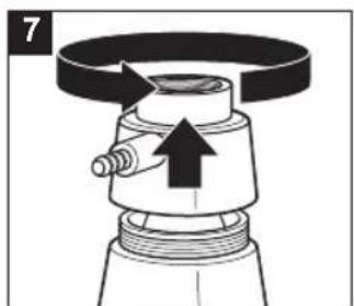
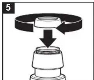
- Place Chamber Cap with Metal Honeycomb Screen on top of Chip Chamber, turning clockwise to secure in place.
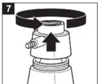
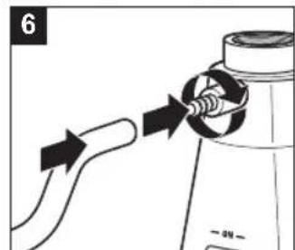
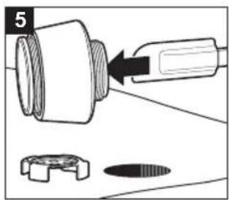
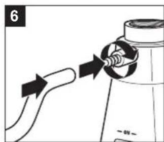
- Replace Smoke Outlet by turning it clockwise in Smoke Chamber opening and push Hose onto Smoke Outlet.
WESTON
ONE-YEAR LIMITED WARRANTY
This warranty applies to products purchased and used in the U.S. and Canada. This is the only express warranty for this product and is in lieu of any other warranty or condition.
This product is warranted to be free from defects in material and workmanship for a period of one (1) year from the date of original purchase. During this period, your exclusive remedy is repair or replacement of this product or any component found to be defective, at our option. If the product or component is no longer available, we will replace with a similar one of equal or greater value.
This warranty does not cover unauthorized repairs or service to products, products sold "as-is" by retailers, glass, filters, wear from normal use, use not in conformity with the printed directions, or damage to the product resulting from accident, alteration, abuse, or misuse.
This warranty extends only to the original consumer purchaser or gift recipient and is not transferable. Keep the original sales receipt, as proof of purchase is required to make a warranty claim. This warranty is void if the product is subjected to any voltage and waveform other than as specified on the rating label (e.g., 120V \~ 60 Hz).
We exclude all claims for special, incidental and consequential damages caused by breach of express or implied warranty. All liability is limited to the amount of the purchase price. Every implied warranty, including any statutory warranty or condition of merchantability or fitness for a particular purpose, is disclaimed except to the extent prohibited by law, in which case such warranty or condition is limited to the duration of this written warranty.
This warranty gives you specific legal rights. You may have other legal rights that vary depending on where you live. Some states or provinces do not allow limitations on implied warranties or special, incidental, or consequential damages, so the foregoing limitations may not apply to you.
To make a warranty claim, do not return this appliance to the store. Please call 1.800.814.4895 (001.216.901.6801 outside the US) or visit WestonBrands.com. For faster service, locate the model, type, and series numbers on your appliance.
PRÉCAUTIONS IMPORTANTES
MODE D'EMPLOI
12

WESTON
GARANTIE LIMITÉE D'UN AN
19
CÓMO USAR
20
23
NOTAS
NOTAS


WESTON
"Y" y/o "MX" y/o "MXY" y/o "Z".
ATTENTION!
PLEASE INSPECT THIS PACKAGE THOROUGHLY FOR MISSING PARTS OR ANY PRODUCT DAMAGE. IF YOUR PRODUCT CONTAINS SHIPPING DAMAGE, PLEASE CONTACT RETAILER FOR ASSISTANCE.
For all other questions regarding product usage, missing parts, product damage, difficulty or warranty activation, please contact the Weston Brands Customer Service Team: 8:00 am to 5:00 pm ET, Monday thru Friday
CustomerService@WestonBrands.com
U.S. Residents Customer Service Line: 1-800-814-4895 (Outside U.S. Call: 001-216-901-6801)
Weston Brands, LLC, Southern Pines, NC 28387
WestonBrands.com
Please DO NOT return this item to the retailer before contacting Weston Brands Customer Service.
SAVE THESE INSTRUCTIONS!
Refer to them often and use them to instruct others.
ATTENTION!
VEUILLEZ INSPECTER CET EMBALLAGE AVEC SOIN POUR Y DÉTECTER
TOUTE PIÈCE MANQUANTE OU ENDOMMAGÉE.
SI DES PIÈCES ONT ÉTÉ ENDOMMAGÉES PENDANT LE TRANSPORT, VEUILLEZ
COMMUNIQUER AVEC LE DÉTAILLANT POUR OBTENIR DE L'AIDE.
CustomerService@WestonBrands.com
Weston Brands, LLC, Southern Pines, NC 28387
WestonBrands.com
CustomerService@WestonBrands.com
Weston Brands, LLC, Southern Pines, NC 28387
WestonBrands.com
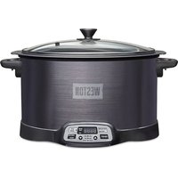
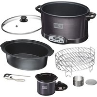



Brand : Weston
Model : 41-0801-W
Category : Slow cooker