CW20K - Water pump Generac - Free user manual and instructions
Find the device manual for free CW20K Generac in PDF.


| Product type | Engine-driven water pump for clear water and water containing solids up to 25 mm |
| Brand | Generac |
| Model | CW20K |
| Fuel | Unleaded gasoline (87 octane min, up to 10% ethanol) |
| Starting type | Recoil starter (manual pull) |
| Connections | Suction and discharge hoses with flanged ends, hose clamps |
| Priming | Manual via orange priming plug, fill with water before starting |
| Maximum suction lift | 8 m (26 ft) |
| Main functions | Water pumping for irrigation, drainage, transfer. Do not use for seawater, drinking water, fuel, chemicals. |
| Safety | Use outdoors only; risk of carbon monoxide; hot surfaces; automatic low oil shutdown (depending on model) |
| Maintenance | Drain water after each use; change engine oil every 100 hours (first at 20 hours); clean air filter every 50 hours; check spark plug every 6 months; drain fuel for storage >30 days |
| Spare parts | Available from Generac customer service (1-888-436-3722) or authorized dealer |
| Repairability | Routine maintenance by user; complex repairs entrusted to an authorized service provider |
| General information | Portable water pump; use on flat, stable surface, minimum clearance 1.5 m around; do not tilt more than 15°; do not submerge the pump |
Frequently Asked Questions - CW20K Generac
User questions about CW20K Generac
0 question about this device. Answer the ones you know or ask your own.
Ask a new question about this device
Download the instructions for your Water pump in PDF format for free! Find your manual CW20K - Generac and take your electronic device back in hand. On this page are published all the documents necessary for the use of your device. CW20K by Generac.
USER MANUAL CW20K Generac
Section 1 Introduction and Safety 1
Introduction 1
Safety Rules 1
Safety Symbols and Meanings ...... 2
Exhaust Hazards 2
Fire Hazards 3
Fuel Hazards 3
Before Starting Equipment 3
When Operating Equipment 3
When Transporting or Repairing Equipment 3
When Storing Fuel or Equipment with Fuel In Tank 3
Section 2 General Information and Setup 4
Know Your Water Pump 4
Product Specifications 4
Emissions Information 4
Remove Contents from Carton ..... 4
Add Engine Oil 5
Add Fuel 5
Assembly 6
Connect the Hoses 6
Priming the Pump 6
Section 3 Operation ....7
Operation and Use Questions .....7
Pump Output 7
High Altitude Operation ....7
Transporting / Tipping ....8
Before Starting Engine 8
Starting the Engine 8
Preventing Water Hammer 9
Water Pump Shut Down 9
After Each Use 9
Section 4 Maintenance and
Troubleshooting ....10
Maintenance Recommendations ...10
Maintenance Schedule 10
Preventive Maintenance ....10
Engine Maintenance ....10
Storage 12
Troubleshooting 13
Section 1 Introduction and Safety
Introduction

WARNING
Consult Manual. Read and understand manual completely before using product. Failure to completely understand manual and product could result in death or serious injury. (000100a)
Thank you for purchasing a Generac Power Systems Inc. product. This unit has been designed to provide high performance, efficient operation, and years of use when maintained properly.
Read this manual thoroughly and understand all of the instructions, cautions, and warnings before using this equipment. If any section of the manual is not understood, contact your nearest independent authorized service dealer or contact Generac Customer Service at 1-888-GENERAC (1-888-436-3722), or www.generac.com with any questions or concerns.
The owner is responsible for proper maintenance and safe use of the equipment. Before operating, servicing or storing this water pump:
- Study all warnings in this manual and on the product carefully.
- Become familiar with this manual and the unit before use.
- Refer to the Assembly section of the manual for instructions on final assembly procedures. Follow the instructions completely.
Save these instructions for future reference. ALWAYS supply this manual to any individual that will use this machine.
The information in this manual is accurate based on products produced at the time of publication. The manufacturer reserves the right to make technical updates, corrections, and product revisions at any time without notice.
Safety Rules
The manufacturer cannot anticipate every possible circumstance that might involve a hazard. The warnings in this manual, and on tags and decals affixed to the equipment are, therefore, not all inclusive. If using a procedure, work method or operating technique that the manufacturer does not specifically recommend, verify that it is safe for others. Also make sure the procedure, work method or operating technique utilized does not render the equipment unsafe.
Throughout this publication, and on tags and decals affixed to the water pump, DANGER, WARNING, CAUTION and NOTE blocks are used to alert personnel to special instructions about a particular operation that may be hazardous if performed incorrectly or carelessly. Observe them carefully. Their definitions are as follows:
DANGER
Indicates a hazardous situation which, if not avoided, will result in death or serious injury.
(000001)
WARNING
Indicates a hazardous situation which, if not avoided, could result in death or serious injury.
(000002)
CAUTION
Indicates a hazardous situation which, if not avoided, could result in minor or moderate injury.
(000003)
NOTE: Notes contain additional information important to a procedure and will be found within the regular text of this manual.
These safety warnings cannot eliminate the hazards that they indicate. Common sense and strict compliance with the special instructions while performing the action or service are essential to preventing accidents.
Safety Symbols and Meanings

DANGER
Asphyxiation. Running engines produce carbon monoxide, a colorless, odorless, poisonous gas. Carbon monoxide, if not avoided, will result in death or serious injury. (000103)

DANGER
Electrocution. Water contact with a power source, if not avoided, will result in death or serious injury. (000104)

DANGER
Explosion and Fire. Fuel and vapors are extremely flammable and explosive. Add fuel in a well ventilated area. Keep fire and spark away. Failure to do so will result in death or serious injury. (000105)

DANGER
Risk of fire. Allow fuel spills to completely dry before starting engine. Failure to do so will result in death or serious injury. (000174)

WARNING
Risk of Fire. Hot surfaces could ignite combustibles, resulting in fire. Fire could result in death or serious injury. (000110)

WARNING
Hearing Loss. Hearing protection is recommended when using this machine. Failure to wear hearing protection could result in permanent hearing loss. (000107)

WARNING
Hot Surfaces. When operating machine, do not touch hot surfaces. Keep machine away from combustibles during use. Hot surfaces could result in severe burns or fire. (000108)

WARNING
Risk of Fire. Verify machine has properly cooled before installing cover and storing machine. Hot surfaces could result in fire. (000109)
WARNING
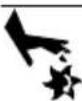
Moving Parts. Keep clothing, hair, and appendages away from moving parts. Failure to do so could result in death or serious injury. (000111)

WARNING
Risk of Falling. Use of machine creates wet areas and trip hazards. Be aware of work area conditions. A fall could result in death or serious injury. (000112)

WARNING
Risk of Falling. Do not use this machine or any components on elevated surfaces. Doing so can result in a fall, serious injury, or death. (000114)

WARNING
Recoil Hazard. Recoil could retract unexpectedly if water pressure is not properly relieved from pump, creating kickback. Kickback could result in death or serious injury. (000113)

WARNING
Consult Manual. Read and understand manual completely before using product. Failure to completely understand manual and product could result in death or serious injury. (000100a)

WARNING
Moving Parts. Do not wear jewelry when starting or operating this product. Wearing jewelry while starting or operating this product could result in death or serious injury. (000115)

WARNING
Vision Loss. Eye protection is required to avoid spray from spark plug hole when cranking engine. Failure to do so could result in vision loss. (000181)
Exhaust Hazards
• The water pump MUST be operated outdoors.
- If you start to feel sick, dizzy, or weak after the water pump has been running, move to fresh air IMMEDIATELY. See a doctor, as you could have carbon monoxide poisoning.
- Keep exhaust gas from entering a confined area through windows, doors, ventilation intakes, or other openings. Warn any occupants inside about the symptoms of carbon monoxide so they know to move to fresh air if they begin to feel ill.
- The use of a carbon monoxide detector inside any occupied premises between the water pump and the occupant is recommended.
- If operating the water pump in a trench or pit, do not enter the area while the engine is running. Carbon monoxide will accumulate in enclosed areas.
- Use a respirator or mask whenever there is a chance that harmful gas or vapors might be inhaled.
- Adequate, unobstructed flow of cooling and ventilating air is critical to correct water pump operation. Do not alter the installation or permit even partial blockage of ventilation provisions, as this can seriously affect safe operation of the water pump.
- This exhaust system must be properly maintained. Do nothing that might render the exhaust system unsafe or in noncompliance with any local codes and/or standards.
Fire Hazards

DANGER
Explosion and Fire. Do not overfill fuel tank. Overfilling may cause fuel to leak and ignite or explode, resulting in death or serious injury. (000204)
- Wipe up any fuel or oil spills immediately. Verify that no combustible materials are left on or near the water pump.
- Reflective exhaust heat may damage the fuel tank, causing fire. Keep at least five (5) feet (152 cm) of clearance on all sides of the pump for adequate cooling, maintenance, and servicing.
- It is a violation of California Public Resource Code, Section 4442, to use or operate the engine on any forest-covered, brush-covered, or grass-covered land unless the exhaust system is equipped with a spark arrestor, as defined in Section 4442, maintained in effective working order. Other states or federal jurisdictions may have similar laws. Contact the original equipment manufacturer, retailer, or dealer to obtain a spark arrestor designed for the exhaust system installed on this engine..
Fuel Hazards
- Turn water pump OFF and let it cool at least two (2) minutes before removing fuel cap. Loosen cap slowly to relieve pressure in tank.
- Fill or drain fuel tank outdoors.
- Keep fuel away from sparks, open flames, pilot lights, heat, and other ignition sources.
- DO NOT light a cigarette or smoke.
Before Starting Equipment
- There is no oil in the engine. The engine crankcase must be filled before starting the engine for the first time. See Add Engine Oil.
- Verify spark plug, muffler, fuel cap, and air cleaner are in place.
- DO NOT crank engine with spark plug removed.
- Keep your hands and body clear from the discharge of the pump.
- Make sure all connections are tight.
- Secure the pump. Loads from the hoses may cause it to tip over.
- Secure the discharge hose to avoid whipping.
When Operating Equipment
- NEVER place discharge hose near a power source.
- Do not allow children near the pump while it is operating.
- DO NOT tip engine or equipment at angle which causes fuel to spill.
- DO NOT pump chemicals or flammable liquids, such as fuel, or fuel oils.
- Secure the pump. Loads from the hoses may cause it to tip over.
- Operate water pump only on level surfaces.
- Do not submerge the pump.
- Never use the water pump or any of its parts as a step. Stepping on the equipment can stress and break parts, and may result in dangerous operating conditions from leaking exhaust gases, fuel leakage, oil leakage, etc.
- DO NOT stop the engine by moving the choke lever to the CHOKE position.
When Transporting or Repairing Equipment
- Transport/repair with fuel tank EMPTY.
- Disconnect spark plug wire.
- For safety reasons, it is recommended that the maintenance of this equipment be performed by an Authorized Dealer. Inspect the water pump regularly, and contact the nearest Authorized Dealer for parts needing repair or replacement.
- When working on this equipment, remain alert at all times.
- Never work on the equipment when physically or mentally fatigued.
- Replacement parts must be of the same type, and installed in the same position as the original parts.
When Storing Fuel or Equipment with Fuel In Tank
Store away from furnaces, stoves, water heaters, clothes dryers, or other appliances that have pilot light or other ignition source because they can ignite fuel vapors.
Section 2 General Information and Setup
Know Your Water Pump

WARNING
Consult Manual. Read and understand manual completely before using product. Failure to completely understand manual and product could result in death or serious injury. (000100a)
Read this manual thoroughly before assembling and operating this equipment. Save this manual for future and immediate reference. Replacement owner's manuals are available at www.generac.com.
Depending on the model, these pumps are designed to pump clear water or water with sediment and particulates up to 1 in. (2.54 cm) in diameter only. Do not use for pumping following:
- Seawater
- Drinking water
- Kerosene
- Fuel, oil, or solvents
• Chemicals
Product Specifications
Refer to the Product Specification Sheet for detailed information on product features and specifications.
Emissions Information
The U.S. Environmental Protection Agency (and California Air Resource Board for equipment certified to CA standards) requires that this engine comply with exhaust and evaporative emission standards. Locate the emissions compliance decal on the engine to determine what standards the engine meets, and to determine which emissions warranty applies. The engine is certified to meet the applicable emission standards on gasoline. It is important to follow the maintenance specifications in Maintenance and
Troubleshooting to verify that the engine complies with the applicable emission standards for the duration of the product's life. Tampering with or altering the emission control system may increase emissions and may be a violation of Federal or California Law. Acts that constitute tampering include but are not limited to:
- Removal or alteration of any part of the intake, fuel, or exhaust systems.
- Altering or defeating the governor linkage or speed-adjusting mechanism to cause the engine to operate outside its design parameters.
Have the engine inspected and repaired by a servicing dealer if these symptoms develop:
• Hard starting or stalling after starting
- Rough idle
- Misfiring or backfiring under load
• Afterburning (backfiring)
- Black exhaust smoke or high fuel consumption
NOTE: Maintenance, replacement, or repair of emissions control devices and systems may be performed by a small engine repair establishment or individual. The manufacturer recommends that all emissions control service work be performed by an Independent Authorized Service Dealer. See emissions warranty for further details.
Remove Contents from Carton
- Remove the loose parts, kits, and inserts included with water pump.
- Open carton completely by cutting each corner from top to bottom.
- Remove and verify carton contents prior to assembly. Carton contents should contain the following:
- Main Unit
- Loose Parts:
- Oil
- Funnel
- Spark Plug wrench
-
Owner's Manual
– Owner's Registration Card
– Product Specifications Sheet -
Wheel Kit (if equipped)
- Hose Kit (if equipped)
- If any items are missing from carton, please call Generac Customer Service at 1-888-436-3722. When calling for assistance, have the model and serial number from the data tag available.
- Record model, serial number, and date of purchase on front cover of this manual.
- Fill out and send in registration card.
Add Engine Oil
CAUTION
Engine damage. Verify proper type and quantity of engine oil prior to starting engine. Failure to do so could result in engine damage.
(000135)
There is no oil in the engine. The crankcase must be filled before starting the engine for the first time.
- Place water pump on a level surface.
- Verify oil fill area is clean.
- See Figure 2-1. Remove oil fill cap and wipe dipstick clean.

natural_image
Illustration of a hand turning a valve with a rotating arrow, next to a water pump (no text or symbols)Figure 2-1. Remove Dipstick
- See Figure 2-2. Add recommended engine oil to the bottom of the oil fill hole (A).
Only high-quality detergent oils classified for service SJ or higher are recommended. DO NOT use special additives.
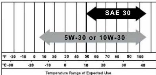
See Figure 2-2. Climate determines proper engine oil viscosity.
bar
| Temperature Range of Expected Use | Value | |---|---| | -20 | - | | -10 | | | 0 | | | 10 | | | 20 | | | 30 | | | 40 | | | 50 | | | 60 | | | 70 | | | 80 | | | 90 | | | 100 | | | Category | Value | | :--- | :--- | | SAE 30 | 30 | | 5W-30 or 10W-30 | 30 |000911
Figure 2-2. Recommended Oil
- Thread dipstick into oil filler neck. Oil level is checked with dipstick fully installed.
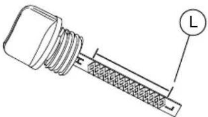
- See Figure 2-3. Remove dipstick and verify oil level is within safe operating range above the lower limit (L).
000116
Figure 2-3. Safe Oil Operating Range
- Install oil fill cap/dipstick and hand-tighten.
Add Fuel

!DANGER
Explosion and Fire. Fuel and vapors are extremely flammable and explosive. Add fuel in a well ventilated area. Keep fire and spark away. Failure to do so will result in death or serious injury. (000105)

DANGER
Explosion and Fire. Do not overfill fuel tank. Overfilling may cause fuel to leak and ignite or explode, resulting in death or serious injury. (000204)
Fuel requirements are as follows:
- Clean, fresh, unleaded gasoline.
• Minimum rating of 87 octane/87 AKI (91 RON). - Up to 10% ethanol (gasohol) is acceptable.
• DO NOT use E85.
• DO NOT use a gas oil mix. -
DO NOT modify engine to run on alternate fuels.
• Stabilize fuel prior to storage. -
Verify equipment is OFF and cooled for a minimum of two minutes prior to fueling.
- Place equipment on level ground in a well ventilated area.
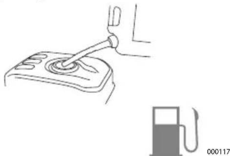
- Clean area around fuel cap and remove cap slowly.
natural_image
Line drawing of a hand using a lever to lift a car intake manifold, with a fuel pump nearby (no text or symbols)Figure 2-4. Add Recommended Fuel
- Slowly add recommended fuel. Do not overfill.
- Install fuel cap.

DANGER
Risk of fire. Allow fuel spills to completely dry before starting engine. Failure to do so will result in death or serious injury.
(000174)
IMPORTANT: It is important to prevent gum deposits from forming in fuel system parts such as the carburetor, fuel hose or tank during storage. Alcohol-blended fuels (called gasohol, ethanol or methanol) can attract moisture, which leads to separation and formation of acids during storage. Acidic gas can damage the fuel system of an engine while in storage. To avoid engine problems, the fuel system should be emptied before storage of 30 days or longer. See Storage. Never use engine or carburetor cleaner products in the fuel tank as permanent damage may occur.
Assembly

WARNING
Consult Manual. Read and understand manual completely before using product. Failure to completely understand manual and product could result in death or serious injury. (000100a)
Connect the Hoses
CAUTION
Equipment damage. Use only hoses and couplings designed for this pump. Incorrect hoses and couplings can cause performance issues and permanent equipment damage. (000197)
NOTE: Appearance of pump may vary. Discharge ports face 90° from inlet on certain models.
NOTE: Hose kit may be sold separately.
- Place water pump in desired operating location.
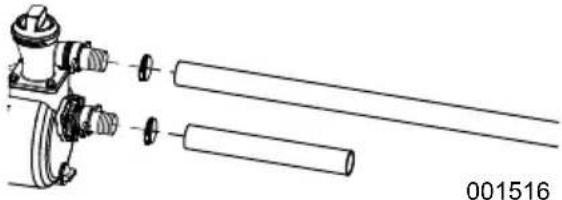
- Attach the flexible discharge hose to the flange (top) by sliding the hose over the barb and securing with a hose clamp.
- See Figure 2-5. Attach the suction hose to the flange (bottom) by sliding the hose over the barb and securing with a hose clamp.
NOTE: Hose attachment styles may vary.
natural_image
Technical line drawing of a mechanical assembly with cylindrical components and fasteners (no text or symbols)Figure 2-5. Typical Hose Attachment
- See Figure 2-6. Attach the strainer to the suction hose.

natural_image
Technical line drawing of a mechanical device with cylindrical components and flanges (no text or symbols)Figure 2-6. Typical Strainer Attachment
CAUTION
Equipment damage. Use recommended strainer to prevent debris from entering the pump. Failure to do so could result in equipment damage.
(000241)
Priming the Pump
CAUTION
Equipment damage. Before starting engine, verify pump is primed with water and suction strainer is submerged. Failure to do so will cause pump damage and void the warranty. (000203)
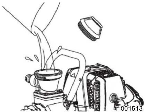
Remove the orange priming cap from the pump and completely fill the pump chamber with clean water. Tighten the cap. DO NOT over tighten.
natural_image
Line drawing of a mechanical device pouring liquid into a container, with no visible text or symbolsFigure 2-7. Water Priming Plug
Section 3 Operation
Operation and Use Questions
If you have any problems operating your water pump, please call Generac customer service at 1-888-GENERAC (888-436-3722).
Placing Water Pump for Use

! DANGER
Asphyxiation. Running engines produce carbon monoxide, a colorless, odorless, poisonous gas. Carbon monoxide, if not avoided, will result in death or serious injury.
(000103)

WARNING
Risk of Fire. Hot surfaces could ignite combustibles, resulting in fire. Fire could result in death or serious injury.
(000110)

WARNING
Hot Surfaces. When operating machine, do not touch hot surfaces. Keep machine away from combustibles during use. Hot surfaces could result in severe burns or fire.
(000108)
It is a violation of California Public Resource Code, Section 4442, to use or operate the engine on any forest-covered, brush-covered, or grass-covered land unless the exhaust system is equipped with a spark arrestor, as defined in Section 4442, maintained in effective working order. Other states or federal jurisdictions may have similar laws. Place the pump on a level surface free from any obstructions or potential hazards. The pump should be placed close to the water level to ensure maximum performance.
- Only operate water pump outdoors in a well ventilated area. Never operate water pump indoors, or in a confined space. Be aware of building openings and ventilation systems where exhaust may enter during use.
- Keep at least five (5) ft (152 cm) of clearance on all sides of water pump including overhead.
- Verify water pump is placed on level ground to avoid tipping during operation.
- Submerge strainer.
NOTE: Suspend the strainer if there is any mud or sand present at the bottom of the water.
- Place discharge hose in appropriate location to drain water. Verify that the hose opening is unobstructed.
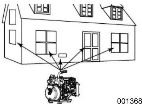
Figure 3-1. Five Feet of Minimum Clearance
CAUTION
Equipment damage. The hose can be damaged if it comes in contact with the hot engine muffler. Keep hose away from muffler during operation. (000124)
Pump Output
See Figure 3-2. Pump output will be affected by the type, length, and size of the suction and discharge hoses. Suction head is the distance (A) from the water intake to the suction port. The pumping height, total head, is the distance (B) from the water intake to the point of discharge. As total head increases, the pump output decreases. The discharge capacity is greater than the suction capacity. Therefore, it is important to keep the suction head less than the total head. The time required to draw water from the source to the pump (self-priming time) can be decreased by minimizing the suction head.
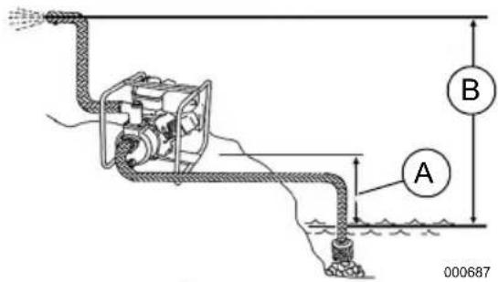
Figure 3-2. Pump Output
High Altitude Operation
This equipment produces maximum suction lift at elevations below 1000 ft (305 m). For every increase of 1000 ft (305 m) above sea level:
- the engine will lose about 3 % of its power - total head will be reduced by about 10 in (25 cm).
Lower atmospheric pressure results in slower engine speeds and reduced water flow through the pump.
Transporting / Tipping
Do not operate, store or transport the equipment at an angle greater than 15 degrees.
Before Starting Engine
- Verify engine oil level is correct.
- Verify fresh fuel level is correct.
- Verify all fittings, gaskets, and couplers are properly secured.
- Verify hoses are properly connected.
- Verify equipment is secure on level ground, with proper clearance and is in a well ventilated area.
NOTE: Pumping water with solids larger than the maximum stated particle size can damage the pump and void the warranty. Maximum particle size is listed on the product specifications sheet. Ensure that correct strainer is attached to the suction hose to prevent pumping larger solids.
Starting the Engine
CAUTION
Equipment damage. Before starting engine, verify pump is primed with water and suction strainer is submerged. Failure to do so will cause pump damage and void the warranty. (000203)
NOTE: For units equipped with a Subaru engine, refer to the Subaru engine manual for specific starting instructions.
- Remove water priming plug and fill the pump with water. Replace water priming plug.
- Move fuel valve lever (A) to ON position.
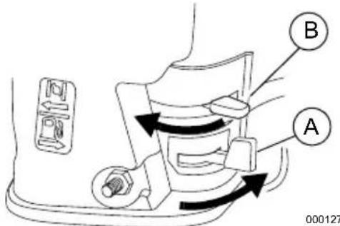
Figure 3-3.Starting the Engine
- Move choke lever (B) to CLOSED position.
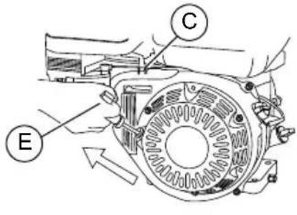
NOTE: For warm engine, leave choke lever in OPEN position. - See Figure 3-5. Move throttle lever (C) about 1/3 away from the MIN position.
- See Figure 3-4. Turn engine switch (D) ON.
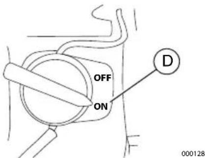
Figure 3-4. Engine Switch
000806
Figure 3-5. Engine Recoil

WARNING
Recoil Hazard. Recoil could retract unexpectedly if water pressure is not properly relieved from pump, creating kickback. Kickback could result in death or serious injury. (000113)
- Grasp recoil handle (E) and pull slowly until you feel some resistance. Then pull rapidly to start engine. Return recoil handle slowly. DO NOT let recoil snap back against recoil housing.
- When engine starts, slowly move choke lever to OPEN position as engine warms. If engine falters, move choke lever to CLOSE position, then to OPEN position.
If engine fails to start after six pulls, move choke lever to "OPEN" position, and repeat step 6. - When the engine is running smoothly, adjust the throttle lever to set the desired engine speed.

WARNING
Risk of Fire. Hot surfaces could ignite combustibles, resulting in fire. Fire could result in death or serious injury.
(000110)

WARNING
Hot Surfaces. When operating machine, do not touch hot surfaces. Keep machine away from combustibles during use. Hot surfaces could result in severe burns or fire. (000108)
Preventing Water Hammer
Water hammer occurs when the discharge flow is suddenly blocked or stopped.
Pressurized water trapped inside the pump can crack the pump housing. To prevent water hammer:
- Do not close the discharge valve while the pump is operating.
- Do not allow vehicles to drive over the discharge hose.
- Do not abruptly compress the discharge hose.
Water Pump Shut Down
- Move throttle lever from fast to slow.
- Turn engine switch OFF
- Move fuel valve lever to OFF position.
- Allow the engine to cool thoroughly.
After Each Use
After cooling, remove the priming plug (A) and drain plug (B) from the pump housing and allow it to drain thoroughly.
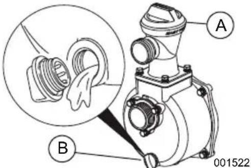
Figure 3-6. Drain Pump Housing
NOTE: DO NOT allow water to remain in pump after use. Trapped water can freeze and crack the pump housing. Pump damage caused by freezing is not covered by warranty.
Follow these procedures after every use:
- Drain pump housing.
- Disconnect hoses.
- Wipe pump with a clean, dry cloth to remove excess water and dirt.
- Store equipment in a clean, dry area.
NOTE: If storing for more than 30 days, see Storage.
Section 4 Maintenance and Troubleshooting
Maintenance Recommendations
Regular maintenance will improve performance and extend water pump life. See an Independent Authorized Service Dealer for service.
Water pump warranty does not cover items subjected to operator abuse or negligence. To receive full warranty value, operator must maintain water pump as instructed in this manual, including proper storage as detailed in Storage.
NOTE: Call 1-888-GENERAC (888-436-3722) with questions about component replacement.
Maintenance Schedule
Follow maintenance schedule intervals, whichever occurs first according to use.
NOTE: Adverse conditions will require more frequent service.
NOTE: All required service and adjustments should be performed each season as detailed in the following chart.
| Before Each Use |
| Check engine oil level |
| Check air cleaner |
| Check and tighten fasteners |
| After Each Use |
| Drain water from pump |
| Every 3 Months or 50 Hours |
| Clean air cleaner* |
| Every 6 Months or 100 Hours |
| Change oil ‡ |
| Clean sediment cup |
| Check and adjust spark plug |
| Clean fuel tank and fuel filter ** |
| Clean spark arrestor (if equipped) |
| Every Year or 300 Hours |
| Replace air cleaner element (paper) |
| Replace spark plug |
| Check and adjust idle speed ** |
| Check and adjust valve clearance ** |
| Every Two Years |
| Check condition of fuel lines and replace if necessary |
| * Service more often in dusty or dirty conditions.** Contact an Independent Authorized Service Dealer.‡ Change oil after the first 20 hours of operation, and every 100 hours thereafter. |
Preventive Maintenance
Dirt or debris can cause improper operation and equipment damage. Clean water pump daily or before each use. Keep area around and behind muffler free from combustible debris.
- Use a damp cloth to wipe exterior surfaces clean.
- Use a soft bristle brush to loosen caked on dirt, oil, etc.
- Use a vacuum to pick up loose dirt a debris.
- Low pressure air (not to exceed 25 psi [172 kPa]) may be used to blow away dirt.
Engine Maintenance
WARNING
Accidental start-up. Disconnect spark plug wires when working on unit. Failure to do so could result in death or serious injury.
(000141)
NOTE: For units equipped with a Subaru engine, refer to the Subaru engine manual shipped with the unit. Maintenance for Subaru engines should be performed according to Subaru recommendations.
Inspect Engine Oil Level

WARNING
Risk of burns. Allow engine to cool before draining oil or coolant. Failure to do so could result in death or serious injury.
(000139)
Inspect engine oil level prior to each use, or every 8 hours of operation.
Add recommended engine oil as necessary. See Add Engine Oil.
NOTE: If equipped with an "Oil Alert System" the system will automatically stop the engine before the oil level falls below a safe limit.
Change Engine Oil
WARNING
Accidental start-up. Disconnect spark plug wires when working on unit. Failure to do so could result in death or serious injury.
(000141)
When using water pump under extreme, dirty, dusty conditions, or in extremely hot weather, change oil more frequently.
NOTE: Properly dispose of used oil in accordance with all local laws and regulations.
Change oil while engine is still warm from running, as follows:
-
Disconnect the spark plug wire from the spark plug and place the wire where it cannot contact spark plug.
-
Place a suitable collection container beneath the engine.
- See Figure 4-1. Remove oil fill cap (A).
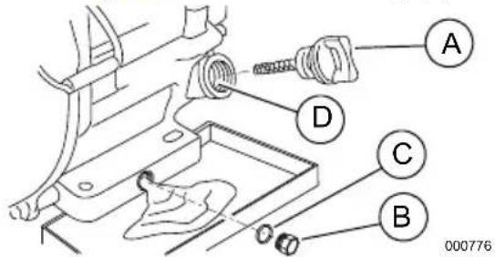
Figure 4-1. Changing Engine Oil
- Remove the oil drain plug (B) and discard the washer (C). Drain oil completely.
- Place a new washer on the oil drain plug. Install oil drain plug and tighten securely.
- Add recommended engine oil as necessary. See Add Engine Oil.
- Install oil fill cap, and finger tighten.
- Wipe up any spilled oil.
- Properly dispose of oil in accordance with all applicable regulations.
Service Air Cleaner
Engine will not run properly and may be damaged if run with a dirty air cleaner. Service air cleaner more frequently in dirty or dusty conditions.
To service air cleaner:
- Remove air cleaner cover.
- Remove filter element(s).
-
Inspect filter element(s) and replace if damaged. To order replacements, contact Generac Customer Service at 1-888-GENERAC (888-436-3722) for the name of your nearest Independent Authorized Service Dealer.
-
Clean foam filter element in warm soapy water. Rinse, and allow to dry thoroughly. Dip in clean engine oil and squeeze out excess oil.
-
Tap paper filter element several times on hard surface to remove dirt. Compressed air (not exceeding 30 psi (207 kPa) can also be used to blow through filter element from the inside.
-
Use a clean, damp cloth to wipe dirt from inside air cleaner cover.
-
Put cleaned or new filter element(s) in place. Verify gasket is in place (if equipped).
-
Install air cleaner cover. Tighten air cleaner screws or fasteners securely.
Service Spark Plug
To service spark plug:
- See Figure 4-2. Clean area around spark plug (A).
- Remove and inspect spark plug.
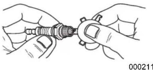
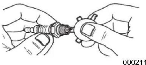
- See Figure 4-3. Inspect electrode gap (B) with wire feeler gauge and replace spark plug if gap (A) is not within 0.028 - 0.031 in (0.70 - 0.80 mm).
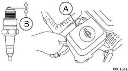
Figure 4-2. Service Spark Plug
natural_image
Illustration of hands holding a small mechanical component (no text or symbols visible)Figure 4-3. Spark Plug Gap
NOTE: Replace spark plug if electrodes are pitted, burned or porcelain is cracked. Use ONLY recommended replacement plug. See product specification sheet.
4. Install spark plug finger tight, and tighten an additional 3/8 to 1/2 turn using spark plug wrench. DO NOT OVERTIGHTEN.
Inspect Muffler and Spark Arrestor (if equipped)
NOTE: It is a violation of California Public Resource Code, Section 4442, to use or operate the engine on any forest-covered, brush-covered, or grass-covered land unless the exhaust system is equipped with a spark arrestor, as defined in Section 4442, maintained in effective working order. Other states or federal jurisdictions may have similar laws.
Contact original equipment manufacturer, retailer, or dealer to obtain a spark arrestor designed for exhaust system installed on this engine.
NOTE: Use ONLY original equipment replacement parts.
Inspect muffler for cracks, corrosion, or other damage. Remove spark arrestor, if equipped, inspect for damage or carbon blockage.
Replace parts as required.
Storage

DANGER
Explosion and Fire. Fuel and vapors are extremely flammable and explosive. Store fuel in a well ventilated area. Keep fire and spark away. Failure to do so will result in death or serious injury.
(000143)

WARNING
Risk of Fire. Verify machine has properly cooled before installing cover and storing machine. Hot surfaces could result in fire.
(000109)
Refer to the following list to prepare equipment for storage.
- DO NOT place a storage cover on a hot water pump. Allow equipment to cool to room temperature before storage.
- DO NOT store fuel from one season to another unless properly treated.
- Replace fuel container if rust is present. Rust in fuel will cause fuel system problems.
- Cover equipment with a suitable protective, moisture resistant cover.
- Store equipment in a clean and dry area.
- Always store water pump and fuel away from heat and ignition sources.
Prepare Fuel System for Storage
Fuel stored over 30 days can go bad and damage fuel system components. Keep fuel fresh, use fuel stabilizer.
If fuel stabilizer is added to fuel system, prepare and run engine according to "Starting the Engine" Run engine for 10-15 minutes to circulate stabilizer throughout fuel system. Adequately prepared fuel can be stored up to 24 months.
CAUTION
Equipment damage. Always run engine with water in the pump priming chamber. Failure to do so could result in equipment damage.
(000243)
NOTE: If fuel has not been treated with fuel stabilizer, it must be drained into an approved container. Run engine until it stops from lack of fuel. Use of fuel stabilizer in fuel storage container is recommended to keep fuel fresh.
- Change engine oil.
- Remove spark plug.
- Pour a tablespoon (5-10cc) of clean engine oil or spray a suitable fogging agent into cylinder.

WARNING
Vision Loss. Eye protection is required to avoid spray from spark plug hole when cranking engine. Failure to do so could result in vision loss.
(000181)
- Pull starter recoil several times to distribute oil in cylinder.
-
Install spark plug.
-
Pull recoil slowly until resistance is felt. This will close valves so moisture cannot enter engine cylinder. Gently release recoil.
Change Oil
Change engine oil before storage. See Change Engine Oil
Prepare Water Pump for Storage
Protect equipment from freezing temperatures. Failure to do so will permanently damage pump and render equipment inoperable. Freeze damage is not covered under warranty.
Protect equipment from freezing temperatures as follows:
- Shut engine off by turning engine start switch to OFF.
- Disconnect hoses.
- Let engine cool.
- Remove water drain plug and drain trapped water.
- Turn fuel valve to OFF.
- Winterize engine per manufacturer specifications.
Store equipment in a clean and dry area.
Troubleshooting
| PROBLEM | CAUSE CORRECTION | |
| Engine will not start, or starts and runs rough. | 1. Engine ON/OFF switch in OFF position.2. Dirty air filter3. Out of fuel.4. Stale fuel.5. Fuel switch in OFF position (if equipped).6. Low oil level (units with low oil shutdown system).7. Spark plug wire not connected to plug.8. Bad spark plug.9. Choke position incorrect.10. Water in fuel.11. Excessively rich fuel mixture.12. Impeller obstructed. | 1. Place Engine ON/OFF switch in ON position.2. Clean or replace air filter.3. Fill fuel tank.4. Replace with fresh fuel.5. Place fuel switch in ON position.6. Fill oil to proper level.7. Connect wire to spark plug.8. Replace spark plug.9. Adjust choke position.10. Drain fuel tank; replace with fresh fuel.11. Contact Independent Authorized Service Dealer.12. Clean impeller. |
| Pump not operating. | 1. Air leak in suction hose.2. Suction and/or discharge hoses blocked.3. End of suction hose not submerged.4. Total head exceeds pump capacity. | 1. Check suction hose and connections for leaks. Tighten or repair.2. Check hoses and strainer. Clear obstructions.3. Increase suction hose length or move pump closer to water.4. Reduce total head or choose a different pump for the task. |
| Weak discharge flow. | 1. Air leakage (intake) at suction side.2. Reduced engine power output.3. Damaged mechanical seal.4. Suction lift too high.5. Suction hose too long, or hose diameter too small.6. Leaking discharge hose or connection.7. Damaged mechanical seal.*8. Impeller obstructed.9. Worn impeller.**10. Engine throttle in SLOW position | 1. Check suction hose and connections for leaks. Tighten or repair.2. Contact Independent Authorized Service Dealer.3. Replace mechanical seal.4. Lower suction lift.5. Shorten suction hose, or increase hose diameter.6. Check discharge hose and connection for leaks. Tighten or repair.7. Replace mechanical seal.8. Clean impeller.9. Replace impeller.10. Increase throttle position. |
| Pump does not prime water, or priming takes a long time. | 1. Air leakage (intake) at suction side.2. Insufficient priming water inside pump casing.3. Water drain plug is loose.4. Engine malfunction.5. Damaged mechanical seal.6. Incorrectly sized suction hose.7. Suction hose is too long.8. Excessive suction lift. *** | 1. Check suction hose and connections for leaks. Tighten or repair.2. Add priming water.3. Tighten water drain plug.4. Contact Independent Authorized Service Dealer.5. Replace mechanical seal.6. Use correct suction hose.7. Move pump closer to water.8. |
| Pump loses prime. | 1. Water level drops below the end of the suction line. | 1. Increase length of suction line or move the pump closer to the water source. |
| Pump shuts down during operation. | 1. No fuel.2. Low oil sensor shuts down unit. | 1. Allow engine to cool for 2 minutes, then fill fuel tank.2. Make sure unit is on flat surface. Check oil level and add more if necessary. |
| Oil leakage at muffler or air cleaner. | Engine failure. Repair or replace. | |
| Water leakage between engine and pump. | Damaged mechanical seal. Replace mechanical seal. | |
| * Mechanical seal damage may be caused by normal wear, overheating, or pumping incompatible fluids.** Excessive impeller wear is primarily due to cavitation. Causes include restricted suction and excessive suction lift.*** Total suction head should not exceed 26 ft (8 m). | ||
Part No. 0K9077 Rev.G 10/16/2018
©2018 Generac Power Systems, Inc.
All rights reserved
Specifications are subject to change without notice.
No reproduction allowed in any form without prior
written consent from Generac Power Systems, Inc.
GENERAC®
Generac Power Systems, Inc.
S45 W29290 Hwy. 59
Waukesha, WI 53189
1-888-GENERAC (1-888-436-3722)
www.generac.com
Bomba de agua
natural_image
Technical line drawing of a mechanical component with threaded end and labeled L (no text or symbols beyond basic lines)000116
natural_image
Line drawing of a hand using a tool to lift a valve on a control panel, with a gas pump nearby (no text or symbols)Figura 2-4. Agregue combustible recomendado
natural_image
Technical line drawing of a mechanical assembly with two cylindrical components and flanges (no text or symbols)natural_image
Technical line drawing of a mechanical device with exploded view, showing internal components and no visible text or symbolsnatural_image
Technical line drawing of a mechanical device pouring liquid into a container (no text or symbols)000806
natural_image
Illustration of hands holding a mechanical component (no text or symbols visible)©2018 Generac Power Systems, Inc.
000115
natural_image
Technical line drawing of a mechanical component with threaded end and threaded base, labeled L (no text or symbols beyond label)natural_image
Line drawing of a hand using a lever to lift a mechanical component (no text or symbols)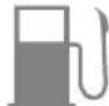
000117
natural_image
Technical line drawing of a mechanical assembly with two cylindrical components and adjustment knobs (no text or symbols)natural_image
Technical line drawing of a mechanical pump assembly with internal components (no text or symbols)natural_image
Technical line drawing of a mechanical device with fluid flow and a component labeled '001513' (no readable text or symbols beyond label)Figure 2-7. Bouchon d'amorçage
Figure 4-2. Entretien de la bougie
natural_image
Illustration of hands holding a small mechanical component (no text or symbols visible)©2018 Generac Power Systems, Inc.
- Section 1 Introduction and Safety 1
- Section 2 General Information and Setup 4
- Section 3 Operation ....7
- Section 4 Maintenance and
- Troubleshooting ....10
- Section 1 Introduction and Safety
- Introduction
- WARNING
- Safety Rules
- DANGER
- CAUTION
- Safety Symbols and Meanings
- Exhaust Hazards
- Fire Hazards
- Fuel Hazards
- Before Starting Equipment
- When Operating Equipment
- When Transporting or Repairing Equipment
- When Storing Fuel or Equipment with Fuel In Tank
- Section 2 General Information and Setup
- Know Your Water Pump
- Product Specifications
- Emissions Information
- Remove Contents from Carton
- Add Engine Oil
- Add Fuel
- !DANGER
- Assembly
- Connect the Hoses
- Priming the Pump
- Section 3 Operation
- Operation and Use Questions
- Placing Water Pump for Use
- ! DANGER
- Pump Output
- High Altitude Operation
- Transporting / Tipping
- Before Starting Engine
- Starting the Engine
- Preventing Water Hammer
- Water Pump Shut Down
- After Each Use
- Section 4 Maintenance and Troubleshooting
- Maintenance Recommendations
- Maintenance Schedule
- Preventive Maintenance
- Engine Maintenance
- Inspect Engine Oil Level
- Change Engine Oil
- Service Air Cleaner
- Service Spark Plug
- Inspect Muffler and Spark Arrestor (if equipped)
- Storage
- Prepare Fuel System for Storage
- Change Oil
- Prepare Water Pump for Storage
- Bomba de agua
Brand : Generac
Model : CW20K
Category : Water pump