
ESwim - Pump DAB - Free user manual and instructions
Find the device manual for free ESwim DAB in PDF.


| Product type | Centrifugal pool pump with electronic inverter |
| Models | ESwim 150 (1.5 HP) and ESwim 300 (3 HP); SVRS version available |
| Dimensions (ESwim 150) | 550 x 300 x 316 mm (22.6 x 12.2 x 12.4 in) |
| Dimensions (ESwim 300) | 574 x 304 x 354 mm (22.6 x 12 x 13.9 in) |
| Empty weight (ESwim 150) | 18 kg (39 lb) |
| Empty weight (ESwim 300) | 21.3 kg (47 lb) |
| Power supply | 220-240 V ±10%, 50/60 Hz |
| Max current (ESwim 150) | 5.6 SFA |
| Max current (ESwim 300) | 10 SFA |
| Max power (ESwim 150) | 1250 W |
| Max power (ESwim 300) | 2250 W |
| Max head | ESwim 150: 16 m (52 ft); ESwim 300: 26 m (85.3 ft) |
| Max flow rate | ESwim 150: 32 m³/h (141 gpm); ESwim 300: 42.6 m³/h (188 gpm) |
| Max working pressure | ESwim 150: 2.5 bar (36.2 psi); ESwim 300: 2.8 bar |
| Max liquid temperature | 40°C (104°F) |
| Protection class | IP55 |
| Motor insulation class | F |
| Main functions | Flow control or fixed speed, hourly programming (8 timers), manual and automatic mode, automatic priming, frost protection, anti-blocking, SVRS (SVRS model) |
| Maintenance and cleaning | Periodic inspection and cleaning of the filter; cleaning of the transparent cover with water and mild soap; annual extraordinary maintenance by qualified personnel |
| Safety | Protection against dry running, motor and electronic overtemperature, short circuit, low/high voltage, motor lock; SVRS anti-suction system (SVRS model) |
| Spare parts and repairability | Spare parts available (see diagram and list in the manual); repair by qualified personnel |
| General information | 104-page user manual; warranty according to applicable law; disposal according to local standards |
Frequently Asked Questions - ESwim DAB
User questions about ESwim DAB
0 question about this device. Answer the ones you know or ask your own.
Ask a new question about this device
Download the instructions for your Pump in PDF format for free! Find your manual ESwim - DAB and take your electronic device back in hand. On this page are published all the documents necessary for the use of your device. ESwim by DAB.
USER MANUAL ESwim DAB
IMPORTANT WARNINGS AND SAFETY RECOMMENDATIONS....2
1 GENERAL 4
1.1 Description 4
1.2 Technical characteristics .... 5
1.3 SVRS Notes (Only applicable to model SVRS)....5
2 INSTALLATION....6
2.1 Hydraulic connections....7
2.2 Pipe Sizing Chart 8
2.3 Plumbing....8
2.4 Electrical connection to the supply line....8
2.5 Electrical connections for auxiliary inputs and outputs 9
3 THE OPERATOR PANEL....11
3.1 Keyboard and Display 11
4 COMMISSIONING....13
4.1 Priming....13
4.2 Guided configuration (WIZARD)....13
5 SWITCHING ON AND USING THE PUMP....14
5.1 Operating mode....14
5.1.1 Regulating modes....14
5.1.2 Command modes....15
5.2 Rapid starting and stopping of the pump ("Manual" mode). 16
5.3 Rapid changing of the setpoint and of the pre-set parameters....16
5.4 Advanced use ("Auto" mode) 17
6 SELECTING THE PREFERRED MODES (MENU)....17
6.1 Menu access and navigation 17
6.1.1 Appearance and opening page of the menu 17
6.1.2 Access to a sub-menu....18
6.1.3 Changing a parameter in the menu....18
6.2 Menu structure 20
6.2.1 Settings....21
6.2.2 Set Points 1-4 23
6.2.3 Set Points 5-8 23
6.2.4 Quick Clean 23
6.2.5 Timers 24
6.2.6 Priming....25
6.2.7 Antifreeze (Protection against water freezing in the pump) 25
6.2.8 Anti-Lock (Protection against mechanical blocking of the pump)....26
6.2.9 Fault History 26
6.2.10 System 27
7 PROTECTION SYSTEMS - LOCKS (FAULT)......27
7.1 Manual reset of error conditions 27
7.2 Automatic reset of error conditions....27
7.3 Viewing the block history....27
8 FACTORY SETTINGS....27
8.1 Restoring the factory settings 29
9 TROUBLESHOOTING 29
9.1 General problems....29
9.2 SVRS problems 29
9.2.1 Suction Blockage....30
10 MAINTENANCE 30
11 DISPOSAL 30
12 GUARANTEE....30
13 PARTS LISTING....95
13.1 Parts diagram....95
13.2 Parts listing....97
ENGLISH
KEY
The following symbols have been used in the discussion:

Situation of general danger. Failure to respect the instructions that follow may cause harm to persons and property.

Situation of electric shock hazard. Failure to respect the instructions that follow may cause a situation of grave risk for personal safety.

Notes and important remarks.
IMPORTANT WARNINGS AND SAFETY RECOMMENDATIONS
This manual concerns the products DAB "E.SWIM" and "E.SWIM SVRS", and is valid for the firmware version 2.x.
GENERAL RISK FACTORS

Before installation, carefully read this manual which contains important information for use of the product. This document must be kept so that it can also be consulted afterwards.
Installation and operation must comply with the local safety regulations in force in the country in which the product is installed.
Everything must be done in a workmanlike manner.
Failure to respect the safety regulations not only causes risk to personal safety and damage to the equipment, but invalidates every right to assistance under guarantee.
INSTALLATION AND MAINTENANCE BY QUALIFIED PERSONNEL

This product should be installed and serviced only by authorized competent and skilled service personnel.
The term skilled personnel means persons whose training, experience and instruction, as well as their knowledge of the respective standards and requirements for accident prevention and working conditions, have been approved by the person in charge of plant safety, authorizing them to perform all the necessary activities, during which they are able to recognize and avoid all dangers.
(Definition for technical personnel IEC 60364.
We suggest special maintenance at least once a year by qualified personnel.

USE ONLY BY COMPETENT PERSONS

The appliance may be used by children over 8 years old and by persons with reduced physical, sensory or mental capacities, or who lack experience or knowledge, on condition that they are under supervision or after they have received instructions concerning the safe use of the appliance and the understanding of the dangers involved. Children must not play with the appliance. Cleaning and maintenance intended to be carried out by the user must not be performed by children without supervision.
MECHANICAL SAFETY

NEVER LET THE PUMP RUN WITHOUT WATER.
Water also performs the functions of lubricating, cooling and protecting the seals: dry running can cause permanent damage to the pump and will void the guarantee.
Always fill the filter before starting the pump.
- Protect the pump from unfavourable weather conditions.
- For a period of inactivity, keep the pump supplied with the "Anti-Lock" function active (paragraph 6.2.9), to avoid mechanical blocking of the pump.
= In case of exposure to frost: - for short periods, keep the pump supplied and activate the "Anti-Lock" function (paragraph 6.2.8); for long periods, disconnect the pump from the power supply, remove all the caps and completely drain the pump body. Keep the caps!
- To use as an outdoor pump, provide suitable protection and install the pump on an insulating base at least 100 mm high.
- Store the pumps in a dry covered area, with constant air humidity.
- Do not wrap the motor in plastic bags! Risk of condensation!
- If testing the seal of the pipes at a pressure higher than 2.5 bar, exclude the pump (close the gate valves before and after the pump).
ENGLISH
- ATTENTION: do not lubricate the O-ring gasket of the transparent cover with oil or grease.
- Use only water and neutral soap to clean the transparent cover, do not use solvents.
- Periodically inspect and clean the pump filter.
- With the pump under the water level, close the gate valves on suction and delivery before removing the filter cover.

The pumps may contain small quantities of residual water from testing. We advise flushing them briefly with clean water before their final installation.
ELECTRICAL SAFETY

Use is allowed only if the electric system is in possession of safety precautions in accordance with the regulations in force in the country where the product is installed (for Italy CEI 64/2).
All repair and maintenance work must be carried out only after having disconnected the pump from the power supply mains.
RISKS LINKED TO HEATING

When the machine is operating, touch only the parts for settings and controls (operator keyboard): the other parts can reach temperatures higher than 40^ C.
Keep inflammable materials far away from the machine. Run the machine in ventilated environments.
TYPES OF PUMPED LIQUIDS ALLOWED

The machine has been designed and made for pumping fresh or salt water from swimming pools, clean or slightly dirty, with a limited content of fibres and small suspended solid particles.
The water temperature must not be higher than 40^ C / 105^ F.
DO NOT USE THE PUMP WITH LIQUIDS WITH DIFFERENT CHARACTERISTICS!
Use of the pump with a concentrated amount of sand can cause early wear and decreased pump performance.
Do not add swimming pool chemicals (such as disinfectants, water treatment substances, etc.) directly to the pump or in front of the pump inlet: undiluted chemicals are aggressive and can damage the pump, while also voiding the guarantee.

SPECIFIC RISKS FOR SWIMMING POOLS, BATHING POOLS AND SIMILAR
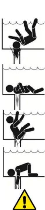

WARNING – Suction Entrapment Hazard. Suction in suction outlets and/or suction outlet covers, which aged, broken, cracked, missing, or unsecured cause severe injury and/or death due to the following entrapment symbols complements of APSP):
Hair Entrapment - Hair can become entangled in suction outlet cover.
Limb Entrapment - Alimb inserted into an opening of a suction outlet sump or suction outlet cover that is damaged, broken, cracked, missing, or not securely attached can result in a mechanical bind or swelling of the limb.
Body Suction Entrapment - Adifferential pressure applied to a large portion of the body or limbs can result in an entrapment.
Evisceration/ Disembowelment - A negative pressure applied directly to the intestines through an unprotected suction outlet sump or suction outlet cover which is damaged, broken, cracked, missing, or unsecured can result in evisceration/disembowelment.
Mechanical Entrapment - There is potential for jewelry, swimsuits, hair decorations, fingers, toes, or knucklesto be caught in an opening of a suction outlet cover resulting in mechanical entrapment.
Note: See section 1.3 for SVRS-related notes.
This is a real risk: in the USA there were 74 documented cases of entrapment and evisceration between 1990 and 2004 (Source: CPSC, USA 2005).
It is therefore obligatory and indispensable to respect all the applicable national and local regulations.

Particular care must be taken in checking periodically that the grids on the suction openings are intact and clean.
Over time, the grids become deteriorated due to age, contact with water and exposure to the sun and to atmospheric agents: they must be checked regularly and with the greatest care, immediately evacuating people from the area if damage is found.
ENGLISH

WARNING- To reduce the risk of entrapment:
To reduce the risk of entrapment the pump must be installed in accordance with the latest federal, state and local swimming pool codes and must be connected to a minimum of two functioning suction outlets per pump or otherwise installed in accordance with the latest APSP-7 standard.
Do not operate pump if any suction outlet cover is damaged, broken, missing or not securely attached.
The use of an approved ASME A 112.19.17 safety vacuum release system (SVRS) is recommended and may be required under federal (U.S.), state or local law.
This pool motor is NOT equipped with a Safety Vacuum Release System (SVRS). SVRS helps prevent drowning due to body entrapment on underwater drains.
In some pool configurations, if a person's body covers the drain, the person can be trapped by suction.
Depending on your pool configuration, a SVRS may be required to meet local, state, and federal requirements.
For information regarding SVRS requirements and the Virginia Graeme Baker Pool and Spa Safety Act visit www.cpsc.gov


Dangerous pressures
During any operation on the system, air can get in and be pressurized. Compressed air can cause the sudden opening of the cover and cause damage, injuries and even death.
DO NOT RELEASE OR WORK ON THE COVER WHEN THE PUMP IS UNDER PRESSURE.

Use only for fixed facilities of swimming pools and bathing pools. Do not use for seasonal facilities that can be dismantled (that is, where the water retaining walls are deflated or disassembled in winter).
RESPONSIBILITY
The Manufacturer does not vouch for correct operation of the electropumps or answer for any damage that they may cause if they have been tampered with, modified and/or run outside the recommended work range or in contrast with other indications given in this manual.
The Manufacturer declines all responsibility for possible errors in this instructions manual, if due to misprints or errors in copying. The Manufacturer reserves the right to make any modifications to products that it may consider necessary or useful, without affecting their essential characteristics.
1 GENERAL
1.1 Description
The system consists of a centrifugal pump and an electronic inverter with advanced control software. It offers a powerful and flexible system for the automation of the water flow for swimming pools, spas, bathing pools and other applications.
The pump is particularly advanced and efficient. The presence of the inverter allows considerable energy saving, and therefore economic advantages and protection for the environment; it also allows the complete automation and programmability of switching on, which can be configured easily and rapidly by means of the wide built-in screen and convenient keyboard.
The "SVRS" version complies with the safety regulations and supplies additional protection against the risks of suction entrapment in swimming pools, bathing pools and similar.
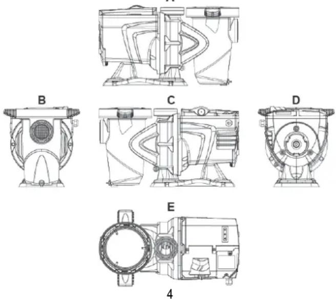
A
ENGLISH
Figure1
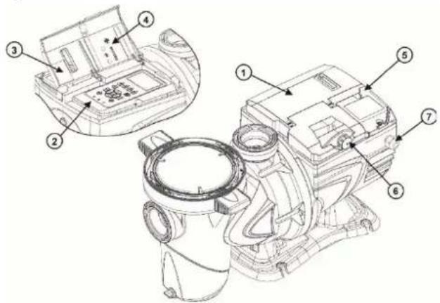
Figure 2
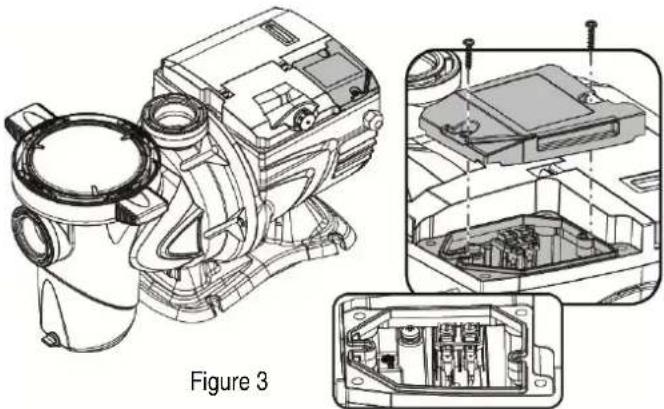
1- User panel cover
2- User panel
3- QR code
4- Quick guide
5- Terminal board cover
6- External connector
7- Power cable inlet
1.2 Technical characteristics
The technical characteristics are summed up in the table below.
| Topic | Parameter | E-SWIM 150 | E-SWIM 300 |
| ELECTRIC POWER SUPPLY | Voltage | 220-240 V +/- 10% | 220-240 V +/- 10% |
| Frequency | 50/60 Hz | 50/60 Hz | |
| Maximum current | 5.6 SFA | 10 SFA | |
| Maximum power | 1250 W | 2250 W | |
| CONSTRUCTION CHARACTERISTICS | Overall dimensions | 550 x 300 x 316 mm / 22.6 x 12.2 x 12.4 in | 574 x 304 x 354 mm / 22,6 x 12 x 13,9 in |
| Empty weight (excluding packaging) | 18 kg / 39 lb | 21,3 kg / 47 lb | |
| Protection class | IP55 | IP55 | |
| Motor insulation class | F | F | |
| HYDRAULIC PERFORMANCE | Maximum head | 16 m / 52 ft | 26 m / 85,3 |
| Maximum flow rate | 32 m3/h / 141 gpm | 42,6 m3/h / 188 gpm | |
| Maximum working pressure | 2,5 bar – 36.2 psi | 2,8 bar – 40.6 psi | |
| WORKING CONDITIONS | Max liquid temperature | 40°C / 104°F | 40°C / 104°F |
| Max ambient temperature | 50°C / 122°F | 50°C / 122°F |
Table 1 – Technical Characteristics
1.3 SVRS Notes (Only applicable to model SVRS)
The Safety Vacuum Release System (SVRS) model is designed to provide an additional layer of protection against body suction entrapment. SVRS model is designed to release body entrapment. It may mitigate evisceration or limb entrapment. It does not prevent hair, mechanical entrapment. It complies with ASME/ANSI A112.19.17 -2010 SVRS standard.
- SVRS devices shall only be installed in conjunction with an ASME A112.19.8 suction fitting, or a 12 in. x 12 in. (305 mm x 305 mm) drain grate or larger, or an approved channel drain system at each suction outlet or drain outlet.
- Check valves and hydrostatic valves shall not be used in suction systems protected by SVRS devices.

WARNING – The presence of a hydrostatic valve in the suction piping has been shown to prolong the high vacuum present at the drain, even though the drain was protected by an SVRS device.
- All SVRS devices shall be factory set or field adjusted to site -specific hydraulic conditions. Once installed, the system shall be tested by simulating an entrapment event.
- All SVRS devices are tested with a single functioning suction outlet.
- A ball, butterfly, or sliding gate valve shall be installed within 2 ft. (0.6 m) upstream from the S VRS (between the SVRS and the protected suction outlet), or a test mat shall be used to cover the suction outlet to simulate an entrapment event. There shall be three simulated
ENGLISH
entrapment tests conducted to verify proper adjustment and operation of the device. Refer to “Suction Blockage” at chapter 9, for the description of two potential checking methods.
- One SVRS device shall be installed for each circulating pump plumbed directly to the suction outlet(s) without the use of valves that could isolate the SVRS device from the suction system.
The reference standard for details and guidelines on how to avoid the risk of entrapment is "ANSI/APSP 7".
Other standards of a local nature may be applicable and obligatory.
In the pump with SVRS, the SVRS function is always active, except for a few moments in particular phases of operation.
It is also possible to disable the SVRS temporarily from the menu (described below); this is useful, for example, when cleaning the pool with a vacuum cleaner.

Before starting the pump with SVRS disabled, always check that there is no one in the pool.
The inactive SVRS condition is indicated by the flashing of the red alarm LED ( ⚠️ ) (fault) and by a flashing message on the display (homepage).
After the SVRS has tripped, it is necessary to ascertain the actual situation in the pool, taking action and providing first aid if needed.
After the SVRS has tripped, the pump can be restarted automatically or by manual RESET (see par. 6.2.1.6).
Pumps with SVRS are sensitive to the presence of air in the pipes, which can cause false tripping of the SVRS. All efforts must therefore be made to limit the presence of air in the system.
2 INSTALLATION

The system must be used preferably in the technical area for installing swimming pool pumps. In no case it must be run if exposed without protection to atmospheric agents.
The place of installation must be well ventilated.
UNPACKING INSTRUCTION
Verify the integrity of the package before opening.
Follow the packing indications for the opening.

- HANDLE WITH CARE

- FRACILE

- THIS SIDE UP

- KEEP AWAY FROM WATER
Remove the pump using the rear handle (under the motor housing) and holding the pump by the suction body.
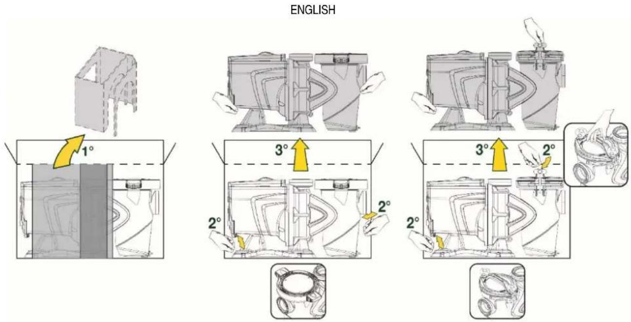
Check the integrity of the pump.
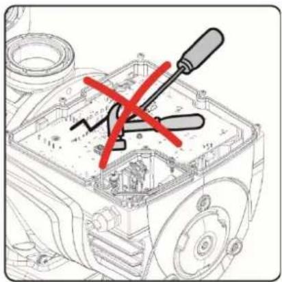
WARNING: Pay attention not to damage the control panel and the electronic board cover. Damaging these two parts could compromise the operation of the pump.
natural_image
Technical diagram of a mechanical assembly with red X marks indicating a disassembled component (no text or symbols present)2.1 Hydraulic connections
Follow these recommendations with care:

- Install the pump horizontally, on a flat and sturdy base, as close as possible to the edge of the pool.
- The pump is able to overcome a maximum difference in level of 4 m (with non-return valve). NOTE: the non-return valve cannot be used in systems with SVRS.
■ Install the filter and the pump in a protected, well ventilated place.
■ Avoid letting the motor be immersed in water.
■ For pump-system connections use only adhesives suitable for plastics.
■ Provide adequate support for the suction and delivery pipes so that they do not weigh down on the pump. - Do not make the couplings between the pipes too tight.
■ Suction pipe diameter > = pump inlet diameter.
■ If a metal pipe is connected, fit a plastic coupling on the pump inlet.
■ The suction pipe must be perfectly airtight.
■ ATTENTION: before connecting the pipes, check that their inside is clean. - ONLY FOR SYSTEMS WITHOUT SVRS PROTECTION: To avoid problems in suction, install a foot valve and make a positive slope of the suction pipe towards the pump.

IMPORTANT: in systems protected with SVRS, neither non-return valves nor hydrostatic valves can be installed (they reduce the efficacy of the protection).
2.2 Pipe Sizing Chart
| MAXIMUMRECOMMENDEDSYSTEMFLOWRATEBYPIPESIZE | ||
| Pipe Size in. [mm] | Maximum Flow Rate GPM [LPM] | Minimum Straight Pipe Length “L” in. [mm]* |
| 1 1⁄2” [50] | 45 [170] | 7 1⁄2” [190] |
| 2” [63] | 80 [300] | 10” [254] |
| 2 1⁄2” [75] | 110 [415] | 12 1⁄2” [317] |
| 3” [90] | 160 [600] | 15” [381] |
* Note: It is recommended that a minimum length of straight piping (shown as "L" in above diagram), equivalent to 5 pipe size diameters, be used between the pump suction inlet and any plumbing fittings (elbows, valves, etc.).
When installing the E.swim, care should be taken to ensure proper pipe and equipment sizing to handle the maximum flow required.
It is recommended to set the maximum flow limit in order to not exceed the maximum flow rate. (See section 6.2.1.5 Pump Limits).
The maximum allowable pipe size is 3" [90 mm].

WARNING – Hazardous Pressure. Pumps, filters, and other equipment/ components of a swimming pool filtration system operate under pressure. Incorrectly installed and/or improperly tested filtration equipment and/or components may fail resulting in severe personal injury or death.
In the case of electropumps without a cable, provide power cables type H05 RN-F for internal use and type H07RN-F for external use, complete with plug (EN 60335-2-41). If the power cable is damaged, it must be replaced by the manufacturer or by their authorised technical assistance service, so as to avoid any risk.
2.3 Plumbing
-
Use Teflon tape to seal threaded connections on molded plastic components. All plastic fittings must be new or thoroughly cleaned before use. NOTE - Do NOT use Plumber's Pipe Dope as it may cause cracking of the plastic components. When applying Teflon tape to plastic threads, wrap the entire threaded portion of the male fitting with one to two layers of tape. Wind the tape clockwise as you face the open end of the fitting, beginning at the end of the fitting. The pump suction and outlet ports have molded -in thread stops. Do NOT attempt to force hose connector fitting past this stop. It is only necessary to tighten fittings enough to prevent leakage. Tighten fitting by hand and then use a tool to engage fitting an additional 1½ turns. Use care when using Teflon tape as friction is reduced considerably; do NOT over -tighten fitting or you may cause damage. If leaks occur, remove connector, clean off old Teflon tape, re -wrap with one to two additional layers of Teflon tape, and re -install connector.
-
Fittings (elbows, tees, valves, etc.) restrict flow. For better efficiency, use the fewest possible fittings. Avoid fittings that could cause an air trap. Pool and spa fitting s MUST conform to the International Association of Plumbing and Mechanical Officials (IAPMO) standards.
2.4 Electrical connection to the supply line
To improve immunity to the possible noise radiated towards other appliances it is recommended to use a separate electrical duct to supply the product.

Attention: always respect the safety regulations! Electrical installation must be carried out by an expert, authorized electrician, who takes on all responsibility.

The system must be correctly and safely earthed as required by the regulations in force.

The mains voltage must be the same as that on the motor data plate. Connect to the mains with a two-pole switch, with contact opening distance of at
natural_image
Technical line drawing of a mechanical device with exploded and assembled views (no text or symbols)least 3 mm. The thermal magnetic circuit breaker and the power cables must be correctly sized. The leakage current to earth is max. 3.5 mA. It is recommended to use a type B differential switch. The system must be adequately sized. The pump must be fed by means of an isolation transformer or a differential switch, which must have a differential operating current no higher than 30 mA.

The mains terminals may still have dangerous voltage when the motor is stopped and for a few minutes after disconnecting from the power mains.
ENGLISH

The line voltage may change when the electropump is started. The line voltage may undergo variations depending on other devices connected to it and on the quality of the line
2.5 Electrical connections for auxiliary inputs and outputs
The pump has a connector for configurable user inputs and outputs.

natural_image
Technical line drawing of a mechanical component with no visible text or symbols
natural_image
Technical line drawing of a mechanical component with a red arrow pointing to a circular feature (no text or symbols present)Figure 4a
The following figure shows the connector contacts, while the table below sums up the arrangement of the signals.
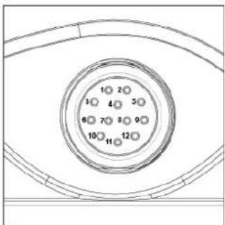
Figure 4b
| PIN | NAME | Wire Color | SIGNAL DESCRIPTION |
| 1 | IN0_D | RED | Digital Input 0 (start/stop) |
| 2 | IN0_A | BROWN | Analog Input 0 (0-10V or 4-20mA) |
| 3 | GND BLACK Earth | ||
| 4 | OUT COM | BLUE | Output relay: Common Contact |
| 5 | OUT NO | WHITE | Output relay: Contact Normally Open |
| 6 | IN1_D | PINK | Digital Input 1 |
| 7 | IN2_D | GREEN | Digital Input 2 |
| 8 | IN3_D | YELLOW | Digital Input 3 |
| 9 | OUT NC | VIOLET | Output relay: Contact Normally Closed |
| 10 | GND GREY Earth | ||
| 11 | IN4_D | RED/BLUE | Digital Input 4 |
| 12 | N.U. PINK/GREY Not used | ||
Tabel 2a – Arrangement of the signals on the connector
The output is made from a relay (clean contact between the RELAY signals pin 1 and pin2), with the following electrical characteristics.
| Characteristics of the output contacts | |
| Type of contact | NO (normally open) |
| Max. bearable voltage [V] 24Vac / 24Vdc | |
| Max. bearable current [A] | 2A -> resistive load 1 A-> inductive load |
| Max. bearable power | 2.5VA / 2W |
Table 2b - Output contact
The functions that can be activated on the output contact are described in paragraph 6.2.5.5.
The following inputs are available (see also par. 6.2.5.4):
- A digital input (between the IN2 and GND signals), with clean contact (maximum voltage 5Vdc, maximum current 1mA); the closed contact means "run", the open contact means "stop".
ENGLISH
- An input for an external analog signal (between the IN1 and GND signals), configurable as 0-10V or 4-20 mA.
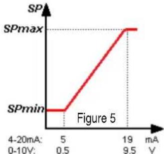
The following figure shows the relationship between the analog signal on input and the setpoint SP to be activated.
See the following parts of this manual for further information on operation.
line
| Voltage (mA) | SP | | ------------ | ------ | | 4-20 | SPmin | | 19 | SPmax |Figure 5

The inputs are not opto-isolated.

To connect to the input and output connector, use only the cable kit DAB.

Attention: keep the cable for the input and output signals well away from the power and alternate supply lines (230V and similar), so as to limit disturbances and interference that can alter the signals.

When it is not in use, the connector on the pump must be kept accurately closed, with the cap well tightened. Only in this way is the necessary resistance to water and damp guaranteed.
3.1 Keyboard and Display
Description of the elements:
- LCD graphic screen
- (Six) LED warning light indicating the active function; each LED indicates the activation of the key next to it.
- LED red warning light ( ), for alarm indication (fault). LED white warning light ( ), lit to indicate that the board is live; if it is blinking, it means that the board is
-
live, but the pump is not enabled (see "RUN/STOP" key below).
-
LED green warning light (C), indicates that the pump is running.
(Four) keys "SET 1-4" for manual control of switching
- on, for directly selecting (or deselecting) a set flow or speed (setpoint).
The table in chapter 8 shows the factory values of the setpoints associated with the keys from "SET1" to "SET4". These values are suitable for most

installations, but they can be easily changed if desired (see 6.2.2)
Key for activating "QuickClean" mode, to command
- quick cleaning or quick recirculating with a high flow rate.
Key for enabling "Auto", mode, for activating the
- automatic control of the pump (which may be timed ("Timers") or given by external signals ("EXT").
Keys for navigating and accessing the menus:
- the "ENTER" key allows you to access the menus and the items on which you are positioned;
- the "arrow" keys allows you to move about on the display or in the active menu, and to select an item; they also allow you to change the value of the selected item.
"OK" key, to confirm and to leave without saving the
-
changes made.
-
"ESC" key, to cancel any changes and leave (without saving).
-
"Reset" key, to cancel the alarms (faults) that may be in progress.
"RUN/STOP" key, to enable or disable running of the
- pump; the pump enabled status is indicated by the steady lighting of the white LED ⏻, which blinks if running of the pump is disabled.
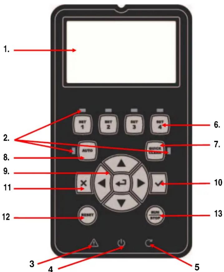
Figure 6

When the pump is running (green LED lit), the pump stops if "RUN/STOP" is pressed, whatever the operating condition, in both "Manual" and "Auto" mode.
However the “RUN/STOP” control is not direct starting control, but only an enabling: if it is pressed with the pump stopped (green LED off), the pump starts only if a mode is active that contemplates switching on at the current moment.
In STOP condition, when the white LED is blinking, the pump can never stop until "RUN/STOP" is pressed.

The only exceptions:
- the "Antifreeze" function can start the pump even in STOP status, to avoid breakages due to frost (see paragraph 6.2.7);
- the "Antilock" function can start the pump even in STOP status, to avoid mechanical blocking of the impeller after long inactivity (paragraph 6.2.8).
The keyboard can be blocked with a "Password", in this way access to the functions can be restricted, to avoid undesired intervention. See paragraph 6.2.1.8.
3.2 Main page of the display (homepage)
This is the appearance of the home page, which appears on the display in normal operating conditions and sums up all the information on system operation.
The information forms three groups:
- The status lines (at the top) provide information on:
o the status (running, stopped) along with the current command (SET1 - SET3, QC, Timer A-H, etc.), or any active Warnings and Faults; in the example in the figure: "System Running" indicates that the system is active, commanded by "TIMER A".
o the active setpoint value ("SP") and the expected time of the end of the active function ("End").

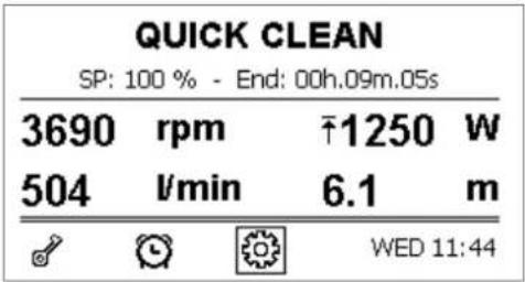
Figure 7a
- The instantaneous values of the electrical and hydraulic magnitudes, which are
grouped in the space in the center of the screen and continuously updated during operation.
The appearance of the symbol (↑) next to a parameter indicates that the parameter has reached its maximum
value, based on current working conditions; the appearance of the symbol ( ) indicates that the parameter has reached its minimum value, based on current working conditions.
- The rapid access bar (at the bottom): contains the date and time with some icons; you navigate on these elements with the right arrow and left arrow keys, and move the selection (highlighted by the box), then press "ENTER" [ ] to go to the selected item.
This gives simple and direct access to the items used most frequently, without having to scroll through the menu. These are the items available and the functions accessed:
- "Configuration" Menu access (see chapter 6),
- Current "Date and time" direct change of date and time (paragraph 6.2.1.3),
- "Timer" 🔊 displays the Timer activation table (paragraph 6.2.5.2),
- "External Control" □ displays the status of the external control (paragraph 6.2.5.3; this symbol is present as an alternative to "Timer" when the external control function has been activated).
- "Key" (or padlock) direct access to the protection system with Password, described in paragraph 6.2.1.8; the symbol represents the current status:
■ (key) Password not entered, free access to all functions;
- (closed padlock) Password entered and active, access to the control keys is prevented;
- (open padlock) Password entered but temporarily deactivated, access is temporarily allowed.
In the case of a pump with SVRS, the homepage shows an additional indication when the pump is running (see figure below).
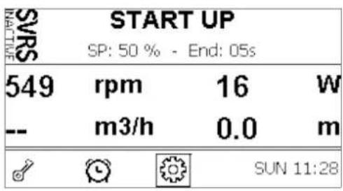
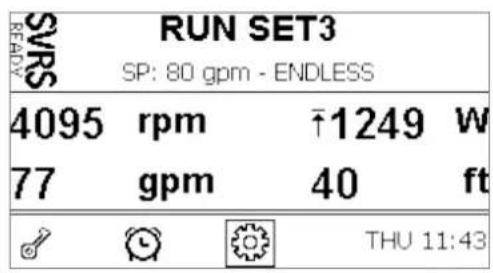
Figure 7b
The figure on the left (where the message "SVRS INACTIVE" is flashing) shows one of the transitory moments when the SVRS is not yet active. In this phase also the red fault LED ⚠️ flashes.
In the case shown in the figure on the right, on the other hand, the SVRS protection is active and ready, as indicated by the message "SVRS READY" (lit with a steady light).
The up arrow symbol, next to the instantaneous power, indicates that a power limitation is in progress. The same symbol can appear in front of other values in the case of active limitations (see paragraph 6.2.1.5).
4 COMMISSIONING
ENGLISH
4.1 Priming
Self-priming can take at least 9.5 minutes to prime to 5 feet at setpoint 150%.
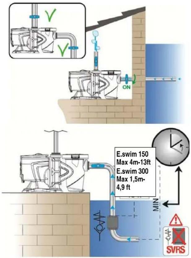
Installation below water level:
Fit one gate valve in the suction pipe and one in the delivery pipe to isolate the pump.
Fill the pump, slowly and completely opening the gate valve in the suction pipe, and keeping the gate valve on delivery open to let the air out.
Figure 8
Installation above water level:
If there are several suction pipes, arrange the pipes and the manifold below water level and reach the pump with only one vertical pipe.
To reduce the priming time, it is recommended to install the pump with as short a suction pipe as possible.
Fill the basket of the filter with water up to the level of the suction mouth.
It is recommended to set the sand filter in backwash mode to speed up priming.
It is strongly recommended to install a check valve on the suction line to facilitate the priming of the pump.
IMPORTANT: non-return valves cannot be installed in systems protected with SVRS.
Figure 9
4.2 Guided configuration (WIZARD)
When switched on for the first time, the device proposes to perform the WIZARD easy configuration, which guides the user in a fast and easy setting of the most important parameters.

It is necessary to perform the WIZARD: the initial system status is that of the factory configuration, and in that the language and the units of measure may not be those used in your country, the weekly clock starts at a random time, and the other parameters may not be suitable for your system.

If you need to revise all these parameters quickly at a later date, you can reload the WIZARD by selecting a specific item on the menu (paragraphs 6.2 and 6.2.1.1).
The WIZARD presents the following pages in sequence:
- Select Language (see also par. 6.2.1.2)
- Select time display mode (24h or am/pm)
- Set current time
- Set current day
- Set Unit of measure of head
- Set Unit of measure of flow
- Set Unit of measure of temperature
- Select Regulating Mode with Keys SET1-SET4 (see also par. 5.1.1)
- Select maximum limit of flow (Qmax) (see also par. 6.2.1.5)
- Select maximum limit of head (Hmax)
- Final confirmation
Each page of the Wizard presents a single parameter to configure, starting from the language.
flowchart
graph LR
    A["Title"] --> B["Key"]
    C["Keys to use (the arrows are not shown)"] --> D["Key"]
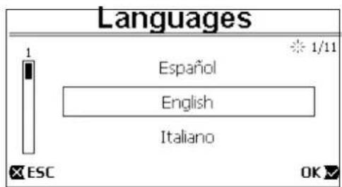
Page in the Wizard (this is page 1 of a total of 11 pages)
Figure 10
ENGLISH
As well as the title, the page shows these indications:
symbol "1/11": indicates the current page number (1), out of the total pages of the WIZARD (11), and of course it changes from one page to the next;
in the centre of the page is the list (or menu) of the various languages available, and the box shows the language currently selected;
the vertical bar, represented on the left, shows the position where we are on the list (or menu) of the languages available; in the example, we are in the first position and the sign on the bar is at the top;
the keys to use are indicated at the bottom (as well as the arrows which, for simplicity, are not shown):
- "OK" key [ OK]: confirms any changes made and allows you to proceed to the nextpage;
- "ESC" key [ ☒ ESC]: cancels any changes made; when you press it again, or if no changes have been made, it returns to the previous page.
As is intuitive, use the up arrow and down arrow keys to scroll through the list of languages to select the one you want, then press "OK" [OK]. The selected language is activated and you proceed to the next page (number 2/11) of the WIZARD.
On some pages, such as the one with hours and minutes, the up and down arrows also allow you to change the value displayed. After having chosen the units of measure and, if necessary, set the limits of the flow rate and head, a page is shown telling you that the Wizard is complete. By pressing "ESC" you can go back to review or change the settings; by pressing "OK" you leave the Wizard and proceed to normal pump operation.
5 SWITCHING ON AND USING THE PUMP
5.1 Operating mode
5.1.1 Regulating modes
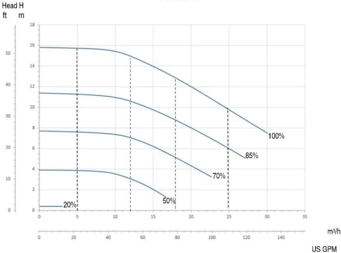
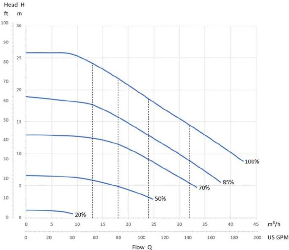
The following diagram shows the indicative curves of the system's hydraulic performances.
E.SWIM 150
line
| US GPM | Head H (ft m) at 20% | Head H (ft m) at 50% | Head H (ft m) at 70% | Head H (ft m) at 85% | Head H (ft m) at 100% | | ------ | --------------------- | --------------------- | --------------------- | --------------------- | ---------------------- | | 0 | 4 | 7.5 | 13 | 16 | 16 | | 5 | 4 | 7.5 | 13 | 16 | 16 | | 10 | 4 | 7.5 | 13 | 16 | 16 | | 15 | 4 | 7.5 | 13 | 16 | 16 | | 20 | 4 | 7.5 | 13 | 16 | 16 | | 25 | 4 | 7.5 | 13 | 16 | 16 | | 30 | 4 | 7.5 | 13 | 16 | 16 | | 35 | 4 | 7.5 | 13 | 16 | 16 |Flow Q
ENGLISH
E.SWIM 300
line
| Flow Q (m³/h) | 20% | 50% | 70% | 85% | 100% | | ------------- | ---- | ---- | ---- | ---- | ---- | | 0 | 3 | 21 | 42 | 61 | 86 | | 40 | 2 | 19 | 41 | 60 | 86 | | 60 | - | - | - | - | - | | 80 | - | - | - | - | - | | 100 | - | - | - | - | - | | 120 | - | - | - | - | - | | 140 | - | - | - | - | - | | 160 | - | - | - | - | - | | 180 | - | - | - | - | - | | 200 | - | - | - | - | - |Figure 11
The inverter automatically regulates the rotation speed of the pump, shifting the work point, as necessary, to any part of the area subtended by the maximum curve (100%).
Regulation during pumping can takes place in flow control mode or in fixed curve mode.
In "flow control" ("Flow") the system assesses the instantaneous flow of water and varies the pump speed so that the flow corresponds to the setpoint, expressed in this case in "m³/h" (cubic metres per hour) or "GPM" (US gallons per minute). In this mode, the work point moves (ideally) on a vertical line, corresponding to the flow value chosen.
In "fixed curve" mode ("Speed %"), the setpoint (expressed as a percentage "%") indicates the operating curve on which you want to be positioned. As can be seen in the figure, the operating point then moves following the trend of the curve chosen, which is similar to the trend of fixed speed curves in traditional pumps.
Generally, when the work point falls below the maximum curve, the system reduces the absorbed power and thus decreases the energy consumption.
The operating software is programmed to limit the motor rpm to a minimum value of 1260; in cases where the system's operating point is theoretically below the range defined by this curve, the software may automatically raise other parameters (e.g. flow rate) above the set value to make the system work within the above-mentioned limits.
5.1.2 Command modes
The system can operate in two control modes: "Manual" mode and "Auto" mode. In "Manual" mode:
- the operator manually commands the switching on of the pup by pressing the keys from "SET1" to "SET4" or "QuickClean";
- the LED next to the key that has been pressed lights up (for example, if "SET1" is pressed the LED above this key is lit).
In "Auto" mode:
- switching on and off are automatically commanded by Timers, which can be programmed as desired on a weekly basis, or by signals arriving from an external control unit ("EXT").
• This mode is disabled when the system leaves the factory.
To activate it, you must first of all configure the necessary parameters (see 6.2.5 and 6.2.6), and then press the "Auto" key (the respective LED lights up).
ENGLISH

"Manual" mode and "Auto" mode can also be used simultaneously; in this case, as will be described better below, the automatism ("Auto") remains active in the background but, if necessary, it can be temporarily overridden by a manual command, which has precedence.
5.2 Rapid starting and stopping of the pump ("Manual" mode).

The pump leaves the factory and is delivered with Priming enabled: if the programming of Priming is not changed (see par. 6.2.6), when switched on for the first time, the pump may start at top speed.
Before pressing "RUN/STOP", make sure that the valves are open, the pipes are not blocked, and keep away from the filter and from parts that can be pressurized.
Check well all the IMPORTANT SAFETY WARNINGS AND RECOMMENDATIONS.
Once the first configuration has been carried out with the WIZARD (in conditions with the white LED ⏻ blinking and the "Auto" LED off), starting the pump is very easy:
- press the key from "SET1" to "SET4" corresponding to the desired setpoint (e.g. "SET1"), or the "QuickClean" key; the LED corresponding to the key pressed lights up, indicating the selection made;
- press "RUN/STOP".
At this point, switching on is enabled and the pump starts; the green running LED lights up, while the white LED is lit with a steady light (indicating that now the system is active).
The system performs startup: the pump starts at a fixed speed (50%) for a few seconds.

Startup is necessary for the pump to switch on correctly, and it is always performed at each start of the motor.
Priming is then performed (par. 6.2.6), if it is enabled (according to factory setting).
After that, the pump continues to run according to the setpoint associated with the "SETx" or "QuickClean" function used (in the example, the "SET1" setpoint).

The factory values are given in chapter 8.
For the “SETx” keys, it is easy to change the setpoint (choosing also between flow or speed) and the other characteristics (duration) by means of the menu (see 6.2.2).
Also the operation associated with the "QuickClean" key can be customized (see 6.2.4).

Pressing a "SETx" or "QuickClean" key puts the pump into "Manual" mode, which has precedence over "Auto" mode: even with "Auto" active ("Auto" LED on), pressing a "SETx" or "QuickClean" key will start the pump with the setpoint associated with the key.
An execution time or duration is also associated with each “SETx” function and with “QuickClean”. The following events may occur while the pump is running:
- the end of the time (or duration) associated with the "SETx" or "QuickClean" key selected previously is reached,
• or the same "SETx" or "QuickClean" key is pressed again;
in both cases, the key function ceases, its LED switches off, and the pump stops.

However, if the "Auto" function was active in the background ("Auto" LED lit), it now takes control of the machine, deciding either to switch off the pump or to switch on with another setpoint, depending on the programming made. So the pump might not switch off.
It is very easy to stop the pump manually: with the pump running, just:
- press "RUN/STOP".
the pump thus stops in any case (*), interrupting all active modes (this means that also "Auto" mode, which may have been active in the background, switches off); the green running LED C switches off. The white LED ⏻ starts to blink, indicating that the system has been disabled.

The SETx setpoint that was active remains if it had the duration "forever" ("ENDLESS"). Otherwise it is deactivated when it is disabled with the "RUN / STOP" button, and its LED turns off.
When "RUN/STOP" is pressed again, the system is re-enabled; the white LED ⏻ is lit with a steady light.
(*) The only exceptions: the Antifreeze and Antilock functions start the pump even if the system is disabled (see paragraphs 6.2.7 and 6.2.8).

After a blackout during operation in Manual mode, the system does not restart unless the SETx key that was lit had the duration "ENDLESS". In this case, the system restarts with the same setpoint as before. Auto mode returns to the status that it was (it is activated if it was active before switching off).
5.3 Rapid changing of the setpoint and of the pre-set parameters
When the pump is running with a "SETx" key pressed (as described above):
- pressing a "SETx" key different from the active one (e.g. "SET3", while "SET1", is active) will perform the setpoint of the new key (for the whole respective duration) and the lighting of the LEDs changes accordingly;
ENGLISH
- instead, by pressing the up arrow and down arrow keys, you can increase of decrease the flow or speed (setpoint) at which the pump is operating. The setpoint value is shown on the display on the homepage (see par. 3.2).
The modified value is stored automatically in the same "SETx" key currently selected (the one with the LED lit).
Also if “QuickClean” has been pressed and the pump is running, the setpoint can be changed with the arrow keys as described above; the new value is saved directly in the “QuickClean” key.

Both a setpoint and an execution time (or duration) are associated with each "SETx" and "QuickClean" key. Unlike the setpoints, the times cannot be changed with the quick method described above; however, they can be changed easily (see 6.2.2 and 6.2.4). The factory values are given in chapter 8.
5.4 Advanced use ("Auto" mode)
On this machine there is a powerful and sophisticated system of timed starting at different setpoints, each with a different duration, which can be planned as preferred on a weekly basis. A simple setting of the parameters is sufficient to perform all the desired cycles completely automatically for seven days. This mode is called “Timers”. (See par. 6.2.5)
It is also possible to have all the pump starts commanded by an external control unit or computer, connected to the input signals (described in 2.3.). This mode is called "EXT", or external (see par. 6.2.5.3). In this case the internal timers do not intervene.
These two modes make up the "Auto" mode.
It is disabled when the pump leaves the factory, because it must be configured specifically for each system (swimming pool, bathing pool, spa, etc.).
To enable "Auto" mode, just go to the menu (par. 6) and, following the indications on the screen, choose the mode (Timers or Ext) and set the values for your system.
After having programmed "Auto" mode, proceed as follows to activate it (in conditions with the white LED ⏻ blinking and the "Auto" LED off):
- with the pump stopped, press the "Auto" key (the LED next to the key lights up),
- then press "RUN/STOP" (the white LED ⏻ lights up with a steady light).
From this moment, the pump starting operations, with their respective setpoints and operating times, will be decided automatically, without requiring any further intervention by the operator.

Even with "Auto" mode active ("Auto" LED on), pressing a "SETx" or "QuickClean" key will start the pump immediately with the setpoint and the duration associated with the key. The pump thus goes into "Manual" mode, which has precedence over "Auto" mode. However, "Auto" mode remains active in the background and resumes control as soon as the function of the key that was pressed ceases.
To deactivate "Auto" mode:
- press the "Auto" key again (the LED next to the key lights up).
If you need to stop the pump manually when it is operating, just:
- press "RUN/STOP".
the pump thus stops in any case (*), interrupting all the active modes.
This means that "Auto" mode stops and also any active manual mode ("SETx" or "QuickClean"); the green running LED C switches off.
The white LED ⏻ starts to blink, indicating that the system has been disabled.
When "RUN/STOP" is pressed again, the system is re-enabled and everything restarts as before. The white LED ⏻ is now lit with a steady light. (*) The only exceptions: the Antifreeze and Antilock functions start the pump even if the system is disabled (see paragraphs 6.2.7 and 6.2.8).
6 SELECTING THE PREFERRED MODES (MENU)
A rapid and intuitive menu system gives access to the various modes, allowing you to activate and configure them as desired.
6.1 Menu access and navigation
The menu is accessed by pressing the "ENTER" key [
bottom of the homepage (par. 3.2).
Enter] when the item "Configuration" is selected in the bar at the
The complete structure of the menu, with all the items of which it is composed, is shown in paragraph 6.2.
6.1.1 Appearance and opening page of the menu
When you enter the menu, the opening page appears, as in the figure:
ENGLISH
The page contains these elements:
- The line at the top shows the page title, in this case "Menu".
- The bar on the left indicates in what position we are with respect to the extension of the menu; in this case we are at the start and the internal sign is at the top end.
- The centre of the page contains a part of the list of items that make up the menu, which we can scroll through with the arrow keys (up and down); the item on which we are positioned is highlighted by 4. — the flashing box (dotted in the figure). The previous menu item (at the top) and the next item (at the bottom) are also shown.
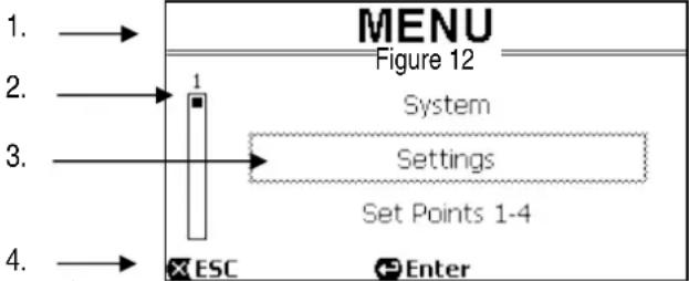
flowchart
graph TD
    A["1. →"] --> B["MENU"]
    C["2. →"] --> D["1"]
    E["3. →"] --> F["System"]
    G["4. →"] --> H["Settings"]
    I["ESC"] --> J["Set Points 1-4"]
    K["Enter"] --> L["Set Points 1-4"]
Figure 12
- The line at the bottom indicates which keys can be used on the page, as well as the arrows (not shown for simplicity). In this case we can press ESC" [ ] to leave, or "ENTER"[ ] to access the selected item.
The following figure shows how the display changes when the down arrow key is pressed.
Now the flashing box (dotted here) highlights the item after the one in the previous situation; in the vertical bar on the left, the internal sign is lower down, showing that we are positioned farther down the items that make up the menu.
When we press the up arrow key, we return to the situation in the previous figure.
The list of items in the menu should by considered as cyclical, that is as a loop: from the last item it returns to the first with the down arrow key. And from the first item it goes to the last with the up arrow key.
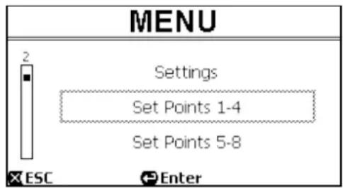
Figure 13
The complete structure of the menu is shown in paragraph 6.2.
6.1.2 Access to a sub-menu
When some items on the menu are accessed, a further menu, or submenu, may open. This happens, for example, on the initial page of the menu, shown above:
Figure 14
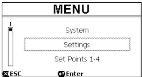
When we press "ENTER" [Enter] to access the "Settings" item, we access the respective "Menu - Settings":
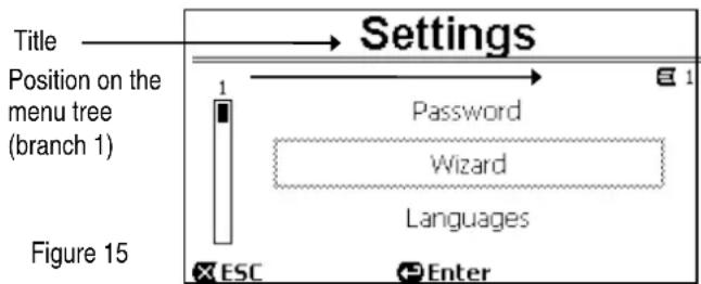
We can also navigate the sub-menus with the arrow keys and access the desired item by pressing "ENTER" [ Enter]. The symbol at top right represents the position on the menu tree; here we are in branch number1.
As well as the complete menu structure, paragraph 6.2 also shows the branch (and item) numbering of all the parts of the menu.
6.1.3 Changing a parameter in the menu
Let us see how to change the value of a parameter, for example the time setting. Suppose we want to set 12:34 as the current time.
ENGLISH
- Navigating in the menu (see table in par. 6.2), we arrive at this page:
- Pressing "ENTER" [Enter] opens the modification of the selected line:
- The figures for the hours are flashing and are changed as desired with the up arrow and down arrowkeys:
- When we reach the desired value, we proceed to the minutes with the right arrow key:
- Now the figures for the minutes are flashing, they too are changed with the up arrow and down arrow keys:
- When the new value is completed (12:34 in the example), we confirm by pressing "OK" [OK], and leave the hour and minute setting, as shown in the following figure. (Instead, if we want to abandon the changes made, we press "ESC" [ESC] to return to the figure in point 1).
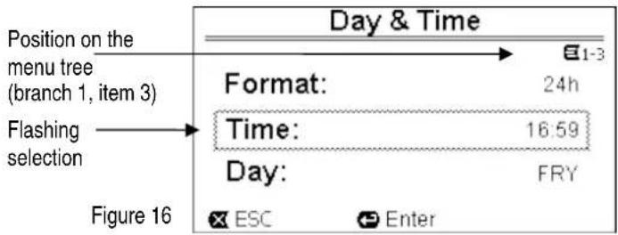
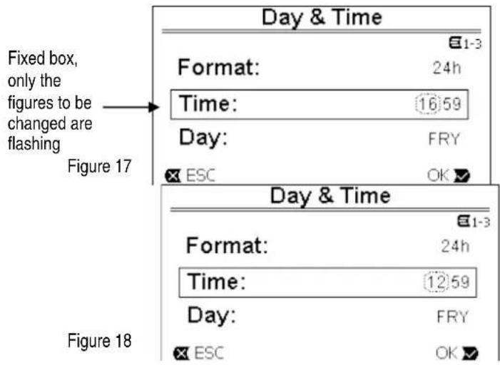
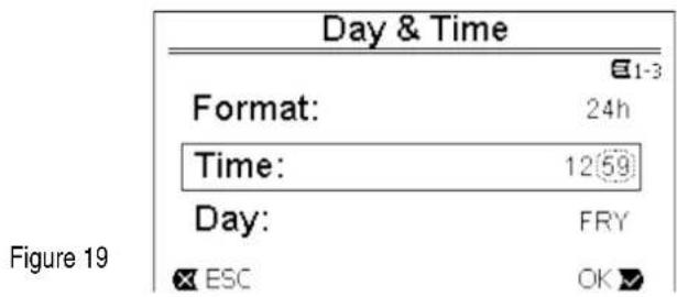
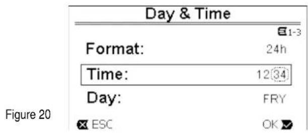
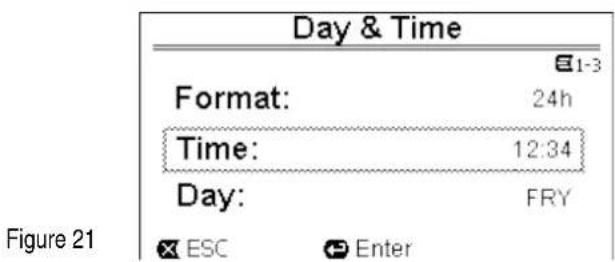
If necessary, we can now move about the page (with the up and down arrow keys) to change the other values (format and day of the week), proceeding in the same way as described so far.
Pressing "ESC" [ ✗ ESC] takes us back in the (sub-) menu structure, and navigation can be continued in each of these. Pressing "ESC" [ ✗ ESC] several times takes us right out of the menu, until we return to the main page (par. 3.2).
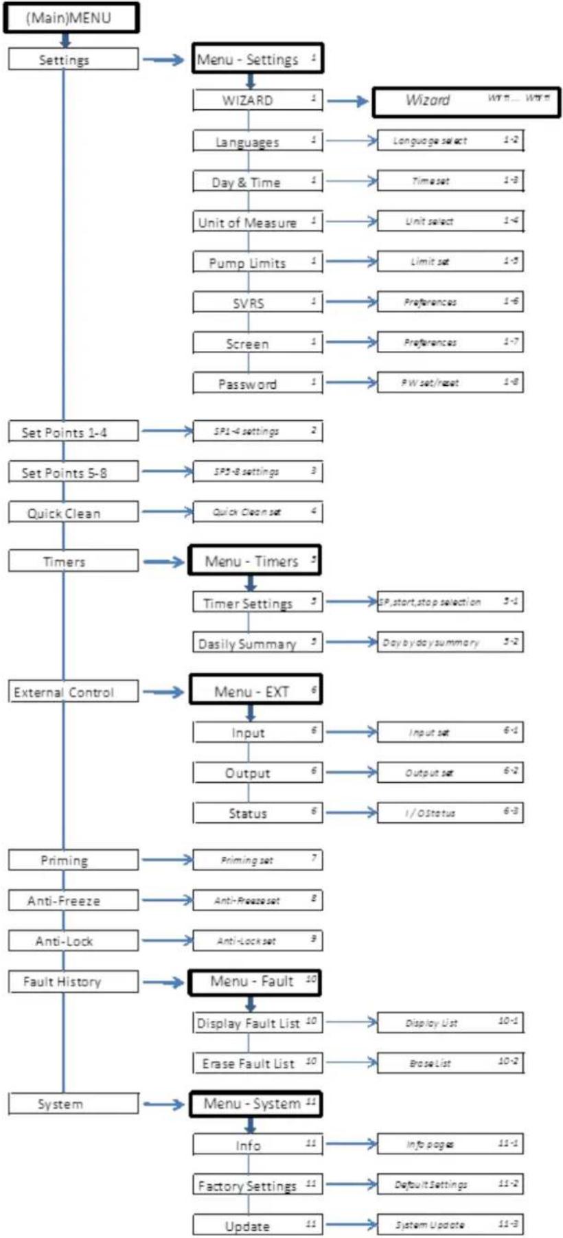
6.2 Menu structure
This is the complete (tree) structure of the menu.
flowchart
graph TD
    A["(Main)MENU"] --> B["Settings"]
    B --> C["Menu - Settings 1"]
    C --> D["WIZARD 1"]
    D --> E["Language 1"]
    E --> F["Day & Time 1"]
    F --> G["Unit of Measure 1"]
    G --> H["Pump Limits 1"]
    H --> I["SVRS 1"]
    I --> J["Screen 1"]
    J --> K["Password 1"]
    K --> L["PW set/reset 1-8"]
    C --> M["Set Points 1-4"]
    M --> N["SP1-4 settings 2"]
    N --> O["Set Points 5-8"]
    O --> P["SP5-8 settings 3"]
    P --> Q["Quick Clean 4"]
    Q --> R["Timers"]
    R --> S["Menu - Timers 5"]
    S --> T["Timer Settings 5"]
    T --> U["Dasily Summary 5"]
    U --> V["Day by day summary 5-2"]
    R --> W["External Control"]
    W --> X["Menu - EXT 6"]
    X --> Y["Input 6"]
    Y --> Z["Output 6"]
    Z --> AA["Status 6"]
    AA --> AB["I/O status 6-3"]
    W --> AC["Priming"]
    AC --> AD["Anti-Freeze set 7"]
    AD --> AE["Anti-Freeze set 8"]
    AE --> AF["Anti-Lock set 9"]
    AF --> AG["Fault History"]
    AG --> AH["Menu - Fault 10"]
    AH --> AI["Display Fault List 10"]
    AI --> AJ["Erase Fault List 10"]
    AJ --> AK["Erase List 10-2"]
    AG --> AL["System"]
    AL --> AM["Menu - System 11"]
    AM --> AN["Info 11"]
    AN --> AO["Factory Settings 11"]
    AO --> AP["Update 11"]
Table 3 Menu Structure
ENGLISH
The numbers, shown on the right in the various boxes, represent the branch and item numbering of the different parts of the menu and are shown on the display (providing a quick reference for the position where we are).
The following paragraphs describe each menu item in detail.
6.2.1 Settings
The “Settings” sub-menu allows us to reactivate the WIZARD (as at the first installation) and to access a series of parameters for customizing the system.
6.2.1.1 WIZARD (loaded from the menu)
The easy configuration Wizard, proposed automatically at the first switch-on (see par. 4.2), can be loaded manually from this menu item.
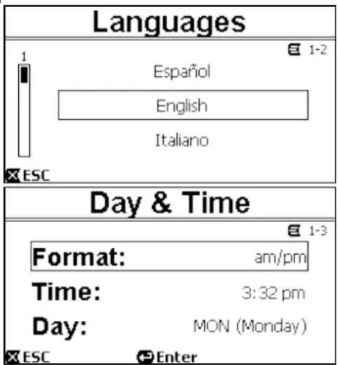
6.2.1.2 Languages
Selection of the language we want to use on the displays.
The choice is made by selecting the desired language (with the up arrow and down arrow keys) and pressing "OK". The factory setting is given in chapter 8.
6.2.1.3 Day & Time
Figure 22
From this page we set the current day of the week and time, along with the preferred format for the hours (that is 1 - 24, or 1 - 12 with AM or PM).
Paragraph 6.1.3 describes in detail how to set the time.
Date and time are not determined when the system leaves the factory.
6.2.1.4 Unit of Measure
Figure 23
Selection of the units of measure used by the machine.
The following table shows the units that can be selected; the choice is separate for each quantity.
| Units of measure displayed | ||
| Quantity | Metric units | Imperial units |
| Head H | m (metres) | ft (feet) |
| Flow Q | m3/h | US GPM |
| Temperature | °C °F | |
Table 4 – Units of measure
The units of measure for flow are “ m^3/h ” (cubic metres per hour) or “GPM” (US gallons per minute). The factory setting is given in chapter 8.
6.2.1.5 Pump Limits
If the system is not able to bear pressures or flows that are too high, it is possible to impose maximum limits on the pump control.
The "MAX" value indicates that there is no active limitation.
The settable upper limits are shown in Table 1.
In the factory setting, these limits are not active, and both parameters are set at "MAX" (see also the table in chapter 8).
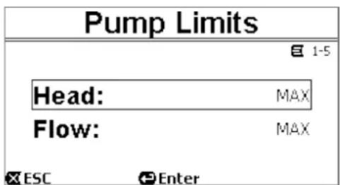
Figure 24

Note: if the upper limits H_max and Q_max are set at values lower than “MAX”, it is possible to set the setpoints even at values larger than the limits; however, during activation these upper limits will never be exceeded (self-limitation of the system) and the setpoints may not be reached.
6.2.1.6 SVRS (only for model with SVRS)
This menu page is dedicated to the "SVRS" function (see also par. 1.3), and it contains the three items shown in the figure.
The factory values of the parameters are given in chapter 8.
The first item allows the automatic restart of the pump after SVRS tripping to be enabled or disabled. Manual restart is always possible by pressing RESET (even with "Auto" set).
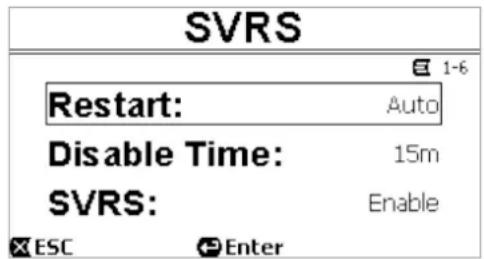
Figure 24A
The second item is used to set the desired time of manual deactivation of the SVRS (between 1 minute and an hour). This is useful, for example, for cleaning the pool with a vacuum cleaner or for other jobs.
The third item allows the start of temporary disabling, which is accomplished:
- by going to the line "SVRS" and pressing Enter,
- changing the value from "Enable" to "Disable" with the vertical arrows
- and then pressing OK.
A countdown shows the time still available before the SVRS is automatically enabled.

Before starting the pump with SVRS disabled, always check that there is no one in the pool.
For example, by pressing the QuickClean button you can now start the pump without the SVRS being able to trip. When the pump is running, the inactive SVRS condition is indicated by the flashing of the red alarm LED ⚠️ (fault) and by a flashing message on the display (homepage).
6.2.1.7 Screen adjustment
The following can be set:
- backlight,
- "Sleep time", that is the time after which, if no buttons are pressed, the display switches off to save energy.
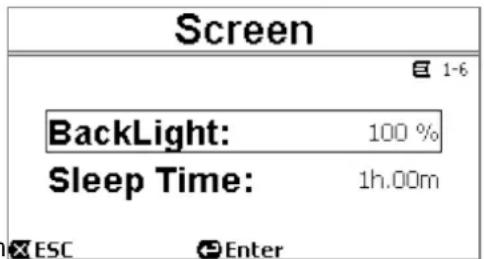
Figure 25
When the display is off (in Sleep mode), pressing a key has the following effect:
- the direct keys (SET1-4, QC, AUTO, RESET, RUN/STOP) perform their function immediately, as well as lighting up the display;
- the navigation keys (ESC, OK, ENTER, arrows) only light up the display and you have to press them again if you want them to be effective (as long as the screen is off, it is not possible to know what effect is really being produced).
When the display switches on, the homepage is always shown. The factory values are given in chapter 8.
6.2.1.8 Password
The inverter has a protection system with a password, with which it is possible to prevent accidental access, or access by unauthorized persons, to the control keys and the programmed parameters.
The password value can be set from the menu page:
- When the password is "0" (as when leaving the factory), all the keys are unlocked and usable and you can freely access the various menus and modify all the parameters. The "key" symbol appears on the homepage (paragraph 3.2).
- When a value other than zero is set in the password field, and confirmed with "OK", the value displayed becomes "XXXX" (hidden) and the protection system is activated. The "closed padlock" symbol appears on the homepage (paragraph 3.2).
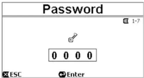
Figure 26
With the protection active, access to all the keys is blocked, except:
- the navigation and menu access keys ("ENTER" key and "arrow" keys): it is possible to navigate in the menu pages and to view the various parameters, but any attempt to change them will require you to enter the password.
When the correct password is entered, the keys are unlocked and the parameters can be changed; the “open padlock” symbol appears on the homepage (paragraph 3.2).
When you have finished changing the parameters, the password can be reactivated from the homepage, by selecting the "open padlock" icon (paragraph 3.2) and pressing "ENTER".
ENGLISH
After eight hours of inactivity (without any keys being pressed), the password will be automatically reactivated anyway.

The password status is always visible, as it is represented with a special page on the homepage; see paragraph 3.2.
The factory value of the password is "0". See also the list of factory values in chapter 8.
If the password is lost, there are two possibilities for editing the parameters of the device:
- Make a note of all the parameter values and reset the device the factory values (see par. 8.1). The reset operation deletes all the device parameters, including the password, and thus re-enables the system.
- Apply to your service centre to receive a code to unlock the device.
6.2.2 Set Points 1-4
The parameters associated with the keys from "SET1" to "SET4" can be viewed and changed under this menu item, through the page shown on the screen.
The first choice to make is whether you want the setpoints "SET1-4" to set the system regulation mode to "Flow" or "Speed %" (see paragraph 5.1.1).
To do this, go to the first parameter shown at the top of the page, press "ENTER" and make the section with the right and left arrow keys, then press "OK" to confirm.
This selection, which is unique for the setpoints 1-4, also modifies the setpoint units of measure, which become respectively:
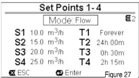
- in Flow: "m³/h" with settable values between 5 and 25 m³/h (or "GPM", between 20 and 110 GPM),
- in Speed: “%” (percent), with settable values between 20% and 100%.
The units of measure and the values assigned to the setpoints (indicated with S1 - S4) are clearly shown on the screen.
To change them, move with the arrows onto the value to be changed, press "ENTER" and change the value with the vertical arrows; press "OK" to confirm the change and move on to the next values.
Each set point has its own duration, indicated on the display with the symbols T1 - T4 and settable between 10 minutes and 18 hours, or "ENDLESS".
The values T1 - T4 are changed in the same way as described above.

The duration value indicates the time that the setpoint remains active, after which it ends; if you want the setpoint to remain always active without interruption, the duration must be programmed as "ENDLESS".
The factory values are given in chapter 8.
6.2.3 Set Points 5-8
This menu items allows you to view and change the parameters associated with the setpoints from 5 to 8.
The setpoints from 5 to 8 cannot be loaded from the keyboard, but they are activated and deactivated only by the TIMERS system (paragraph 6.2.5). Unlike setpoints 1-4, they do not have any associated duration, as the activation time is decided always and only by the TIMERS.
Like the setpoints 1-4, here too you choose the regulation mode by flow or speed (see paragraph 5.1.1) and the setpoint values, indicated with S5 - S8.
The procedure for selection and changing is identical to the one described in the previous paragraph. The factory values are given in chapter 8.
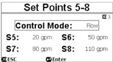
Figure 28

To simplify the use of the Timers, it is recommended to assign increasing values to the setpoints, from Setpoint 5 to Setpoint 8 (see par. 6.2.3 and following).
6.2.4 Quick Clean
The "QuickClean" key allows you to perform a rapid wash of the system or fast recirculation, for example by cleaning, suction, adding chemicals, and so on. Its parameters are:
- setpoint in Speed %, settable between 20% and 100%;
- duration (execution time), settable between 1 minute and 10 hours.
The factory values are: maximum curve 100%, for ten minutes (see also chapter 8).
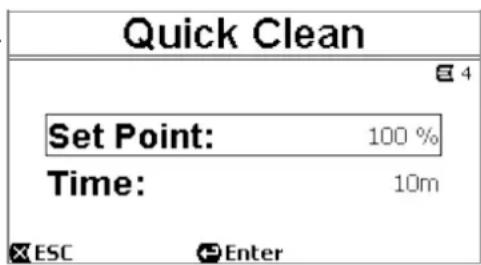
Figure 29
ENGLISH
6.2.5 Timers
There are eight different timers on the machine, from Timer A to Timer H, each of which allows timed starting and stopping, on a weekly basis, of a setpoint chosen from Set Points 5-8. With a simple setting you can thus automatically carry out all the desired cycles, repeated weekly. To use this mode, see also paragraphs 5.1.2 and 5.4.
From this sub-menu you can:
- set the timers,
- view the currently active program.
When the system leaves the factory, the timers are disabled and not programmed.
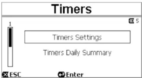
Figure 30
6.2.5.1 Timer Settings
Programming of the timers is carried out in "table" form: a table appears on the display, showing the activation data of each of the eight Timers A - H.
The following are set for each timer:
- the START time,
- the STOP time,
- the desired SET POINT (under the symbol "S"), chosen among the 4 speeds/flows of the Set Points 5-8,
- the days of the week on which the timers are to be activated (the boxes for the days are marked), and lastly it is possible to enable or disable the timer, by marking or not marking the box under the symbol "E".
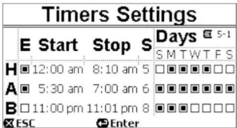
Figure 31
The data are accessed and modified with the “Enter” and arrow keys, etc. following the normal rules applied to all the menus (see an example in par. 6.1.3).
Another special function is available: holding down "Enter" [ Enter] for three seconds makes a copy of the timer on which you are positioned; moving to another timer and holding down "OK" [ OK ] for three seconds pastes the whole configuration of the first timer onto this one; the operation is then confirmed by pressing "OK" [ OK ] or cancelled by pressing "ESC" [ ESC ].
This special function makes it particularly easy to repeat the data of a timer if you want to change, for example, only one parameter, such as the day or the setpoint.
If you want a timer to be activated every day, clearly it is sufficient to mark the boxes of all seven days of the week for that timer.
The possibility of enabling or disabling a timer may be useful, for example, at the change of season, allowing you to exclude a timer but leaving all its data set to be used again later.

If two or more timers have been programmed as “active” at the same time, the one that comes first in alphabetical order will have precedence, that is Timer A will have precedence over Timer B and so on.
6.2.5.2 Timer daily summary
The set timers are displayed like a chrono-thermostat: the profile of the timer used as a function of the time is shown for each day of the week. This offers an immediate check of the operation of each whole day.
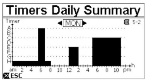
bar
Timers Daily Summary | Hour | Time (h) | |---|---| | am | 0 | | 2 | 0 | | 4 | 0 | | 6 | 1 | | 8 | 0 | | 10 | 0 | | 12 | 1 | | 2 | 0 | | 4 | 0 | | 6 | 0 | | 8 | 0 | | 10 | 1 | MON ESC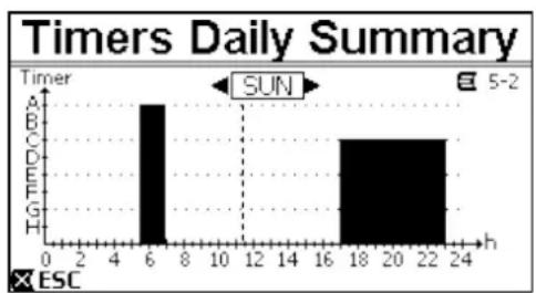
bar
Timers Daily Summary | Hour | Time (h) | | :--- | :--- | | 6 | 6 | | 18 | 18 | | 22 | 22 | | 24 | 24 |Figure 32 A
vertical dotted line indicates the present moment on the graph.

Since the timers are shown with a height decreasing from Timer A to Timer H, it is convenient to associate setpoints decreasing gradually from Timer A to Timer H. In this way the table also becomes indicative of the setpoint value.
6.2.5.3 External Control
The machine can be controlled by an external control unit or by a PC. To use this mode, see also paragraphs 5.1.2 and 5.4.
This function is set by means of this sub-menu, which considers separate items for inputs and outputs, plus an item ("Status") that sums up the current status of the inputs and outputs.
This function is disabled and not configured when the system leaves the factory. The electrical characteristics of the inputs and outputs are given in paragraph 2.3.
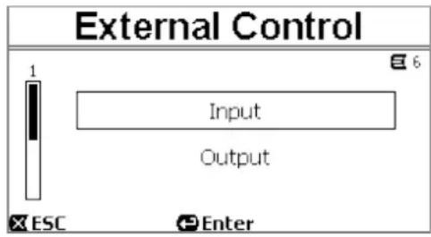
Figure 33
6.2.5.4 Configuration of the Inputs
The inputs are configured from this menu page.
From this item, you first set the general enabling of "EXT External Control" mode. The inputs include:
- a digital input for the START/STOP control;
- an analog input, through which the setpoint to be activated is communicated.
The analog input can be selected "in volgage 0-10 V" or "in current 4-20mA".
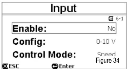
The setpoint to be activated can be chosen for regulation by Flow or regulation by Speed % (see paragraph 5.1.1.)
6.2.5.5 Configuration of the Outputs
A relay output (clean contact), normally open, is available. It can be configured to signal:
- the running status ("RUN") □ When the pump is running the contact closes, and it remains open when the pump is stopped.
- the system block status ("FAULT") L In the case of blocking errors the contact opens, whereas it remains closed when faults are absent.
The outputs are configured from this menu page. The factory values are given in chapter 8.
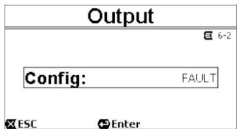
Figure 35
6.2.6 Priming
Each time the pump starts, the system performs the priming procedure (if enabled). Priming consists of two phases:
- At the end of pump startup (as described in par. 5.2), the flow is checked; if it regular, Priming has already been completed and it passes to the conditions of the active setpoint.
- If this is not the case, the system has discharged and must be primed again: it now enters the second phase, where the pump is activated at Maximum Priming Speed, until it is primed or at any rate for all the time specified by the parameter "Max Priming Time".
Here too, if priming has been successful, it proceeds regularly according to the active setpoint.
But if priming has not been successful, it goes into "NoPriming" fault status (block). On blocks and resets, see chapter 7.
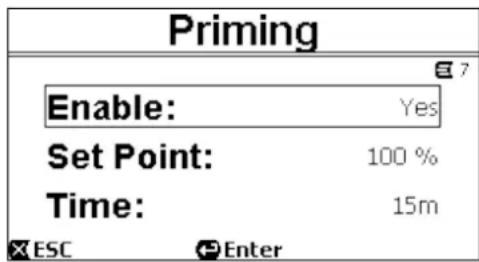
Figure 36
The "Priming" item on the menu allows you to:
- enable or disable the function (factory value: enabled);
- select the setpoint between 50% and 100% (E.swim 150)
- select the setpoint between 50% and 150% (E.swim 300)
- select "Time", between 1 and 30 minutes.
The factory values are given in chapter 8.

In installations below water level, it is not generally necessary to perform Priming each time the pump is started (and it can be disabled).
The maximum speed during priming ("Max Priming Speed") can be reduced in the case of systems that are not able to withstand high speeds.
6.2.7 Antifreeze (Protection against water freezing in the pump)
As is known, the formation of ice, that is the change of state of water from liquid to solid, causes an increase in volume, with the risk of breakages for the systems containing water.
For this reason it is generally recommended to empty any pump and hydraulic system during winter, when the temperatures are close to freezing
point.
However, our system is equipped with the “Antifreeze” function, which automatically rotates the pump if the temperature falls to values close to zero. The water inside the pump is thus kept moving and slightly heated, thus limiting the risk of the formation of ice.

This function protects the pump, but it cannot generally prevent the formation of ice in the swimming pool or in other parts of the system.
The temperature sensor is fitted close to the motor and does not directly feel the water temperature, but that of the pump motor assembly.
If the pump is in a technical room, the outdoor temperature may be lower, even much lower, than the one measured by the sensor.

ATTENTION: The Antifreeze protection works only as long as the system is regularly powered: with the electric power disconnected or in the absence of current (even accidental, such as after a blackout) the protection cannot work. So it is advisable not to leave the system loaded during long periods of frost in winter, but empty it accurately.

In cases of inactivity, it is advised not to disconnect the electric power to keep the antilock protection active (see the following paragraph).

The intervention of the Antifreeze function turns the pump even if the system is in STOP status (white led ⏻ blinking), and is not influenced by the active operating mode (manual or automatic).
If you want to prevent the Antifreeze function intervening and turning on the motor, the function must be disabled.
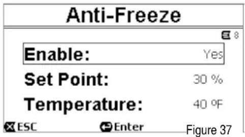
The "Antifreeze" item on the menu allows you to:
- enable or disable the function (factory value: enabled);
- select the pump rotation speed during the intervention of Antifreeze: between 20% and 100%;
- choose the intervention temperature of Antifreeze, between 4°C and 10°C (between 40°F and 50°F).
The factory values are given in chapter 8.
6.2.8 Anti-Lock (Protection against mechanical blocking of the pump)
This function prevents mechanical blocks occurring in the case of long inactivity; it acts by periodically turning the pump, at a very low speed that does not create a head. When the function is enabled, the pump performs an unlocking cycle lasting about one minute every 23 hours (elapsed without any start of the pump).
The "Antilock" item on the menu allows you to enable or disable the function (factory value: enabled).

ATTENTION: The Antilock protection works only as long as the system is regularly powered: with the electric power disconnected or in the absence of current (even accidental, such as if the automatic switches have blown due to a storm) the protection cannot work.

The intervention of the Antilock function turns the pump even if the system is in STOP status (white led ⬆ blinking), and is not influenced by the active operating mode (manual or automatic).
If you want to prevent the Antilock function intervening and turning on the motor, the function must be disabled.
6.2.9 Fault History
This item on the menu allows you to consult the fault history and erase it.
Pressing "ENTER" on the second item gives access to the page that allows you to delete the list.
Instead, if you press "ENTER" on the first item, it gives access to the list of faults in the memory, which you can scroll through with the arrow keys (not indicated on the display).
The faults are shown in chronological order, starting from the most recent one, up to the one that occurred farthest back in time. The list is scrolled with the up arrow and down arrow keys.
The maximum number of faults that can be stored and displayed is 16; when this number is reached, the list starts to overwrite the oldest ones.

Figure 38
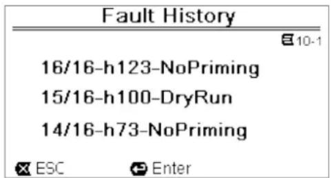
Figure 39
6.2.10 System
This menu item groups together a number of pages for the advanced user.
The "Info" page shows information about the operating status, totals and statistics (operating hours, pumped volume, absorbed energy) and other data (such as firmware version, serial number). The totals and statistics shown are overall and partial; the partial totals can be reset (Reset) by the user (by holding down "OK" [ OK ] for 3 seconds, as indicated on the display).
The "Factory Settings" page allows the resetting of the factory values (see also paragraph 8.1).
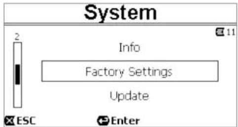
Figure 40
The "Update" page allows the updating of the product firmware, which can be done via wireless using the special device "DAB E.sylink".
7 PROTECTION SYSTEMS - LOCKS (FAULT)
The device is equipped with protection systems to preserve the pump, the motor, the supply line and the inverter. If one or more protections trip, the one with the highest priority is immediately notified on the display.
Faults cause switching off of the motor and lighting of the red warning LED
In some types of fault, the motor restarts as soon as normal conditions are restored; in others, attempts at automatic reset are carried out after a certain space of time.
It is also possible to try to cancel the error condition manually (see the following paragraphs). If the error condition remains, you must take steps to eliminate the cause of the fault.
7.1 Manual reset of error conditions
In block (fault) status, the user can cancel the current error and force a new attempt by pressing and releasing the "Reset" key.
If the action is successful, the red warning LED(⚠️) goes out and the system returns to normal operation. Instead, if the error condition remains, you must take steps to eliminate the cause of the fault.
| Fault No. | Description on the display |
| e1 / e14 | Internal error |
| e15 | Motor phases short circuit |
| e16 | Short circuit to earth |
| e17 / e19 | Internal error |
| e20 / e22 | Electronic excess temperature |
| e23 | Low mains voltage |
| e24 | High mains voltage |
| e25 | Motor excess temperature |
| e26 | Motor blocked |
| e27 Dry operation | |
| e28 | Pump not primed |
| e29 No current | |
| e33 | Tripping of SVRS (“SVRS trip”) |
Table 5 – List of Faults
7.2 Automatic reset of error conditions
For some types of fault, automat reset attempts are contemplated. In particular for:
- e27 Dry operation
- e28 Pump not primed
a new attempt is made after a few minutes, and repeated cyclically.
If an attempt is successful during the reset sequence, the sequence is interrupted, the red warning LED (⚠️) goes out and the system returns to normal operation.
In the case of the “Excess temperature” faults, the system resume operation as soon as the temperature returns within the normal operating range.
For the error "e33 SVRS trip", see paragraphs 1.3 e 7
7.3 Viewing the block history
The list of the faults and blocks that have occurred most recently can be consulted under the menu item "Fault History". See paragraph 6.2.9.
8 FACTORY SETTINGS
The system leaves the factory with a series of preset parameters, which may be changed according to the requirements of the plant and of the user. Each change of the settings is automatically saved in the memory.
The factory (or default) settings are summed up in the following table. You can make a note of the values modified for your own installation in the "MEMO" column.

As indicated in the table, some default values may differ depending on the market for which the system is intended.
If desired, it is possible to restore the default settings, proceeding as described in paragraph 8.1.
ENGLISH
| Factory settings | ||||||
| Menus | Function | Parameter | Value (*) | MEMO | ||
| 1.5 CV | 3 CV | |||||
| 1-2 | Language | English | ||||
| 1-3 | Time format | 24h | AM PM | |||
| 1-4 | Unit of Measure | Head Unit | m (metres) | ft (feet) | ||
| Flow Unit m3/h US GPM | ||||||
| Temperature Unit | °C | °F | ||||
| 1-5 | Pump Limits | H max (head) MAX | ||||
| Q max (flow) | MAX | |||||
| 1-6 | SVRS(only pumps with SVRS | Restart Auto (after 5 min) | ||||
| Disable Time | 15 min | |||||
| SVRS Enable | ||||||
| 1-7 | Screen | Sleep Time | 1:00 h | |||
| 1-8 | Password | value | 0 (not active) | |||
| 2 | Set Points 1-4 | type of setpoint | Speed % | Speed % | ||
| 2 | SET1 | setpoint Q | 5 m3/h | 20 GPM | 13 m3/h | 60 GPM |
| setpoint % | 50% | |||||
| duration | ENDLESS | |||||
| 2 | SET2 | setpoint Q | 12 m3/h | 50 GPM | 18 m3/h | 80 GPM |
| setpoint % | 70% | |||||
| duration | ENDLESS | |||||
| 2 | SET3 | setpoint Q | 18 m3/h | 80 GPM | 24 m3/h | 110 GPM |
| setpoint % | 85% | |||||
| duration | ENDLESS | |||||
| 2 | SET4 | setpoint Q | 25 m3/h | 110 GPM | 32 m3/h | 140 GPM |
| setpoint % | 100% | |||||
| duration | ENDLESS | |||||
| 3 | Set Points 5-8 | type of setpoint | Flow | Flow | ||
| 3 | SET5 | setpoint Q | 5 m3/h | 20 GPM | 13 m3/h | 60 GPM |
| setpoint % | 50% | |||||
| 3 | SET6 | setpoint Q | 12 m3/h | 50 GPM | 18 m3/h | 80 GPM |
| setpoint % 70% | ||||||
| 3 | SET7 | setpoint Q | 18 m3/h | 80 GPM | 24 m3/h | 110 GPM |
| setpoint % | 85% | |||||
| 3 | SET8 | setpoint Q | 25 m3/h | 110 GPM | 32 m3/h | 140 GPM |
| setpoint % | 100% | |||||
| 6 | External Control | Input: Enable | NO | |||
| Config. | 0-10 V | |||||
| Control Mode | Speed % | |||||
| Output: Config. | Fault | |||||
| 4 | Quick Clean | setpoint | 100% | |||
| duration | 10 min | |||||
| 7 | Priming | function | enabled | |||
| Max Priming Speed | 100% | |||||
| Max Priming Time | 15 min | |||||
ENGLISH
| 8 | Anti-Freeze | function | enabled | ||
| speed | 30% | ||||
| temperature | 4 °C | 40 °F | |||
| 9 | Anti-Lock | function | enabled | ||
| (*) Factory value on some markets | |||||
Table 6 – Factory (default) settings
8.1 Restoring the factory settings
To reset the factory values, use the "Factory Settings" page of the "System" menu (par. 6.2.10).
Alternatively, switch off the device, wait until the display has switched off completely, press and hold down simultaneously the two keys "SET1" and "SET4" and turn on the power; release the keys only when the messages appear on the display. This restores the factory settings (consisting of a message and a rereading on EEPROM of the factory settings permanently saved in the FLASH memory and listed in the table above).
Once all the parameters have been set, the device returns to normal operation.

NOTE: this operation obviously deletes all the parameters that have previously been modified by the operator. Once the factory values have been restored, it will therefore be necessary to reset all the parameters that characterise the system, as at the first installation: for the sake of convenience, the system again proposes the WIZARD (paragraph 4.2).
9 TROUBLESHOOTING
9.1 General problems
The pump does not start (display off): No
electric power.
Check that there is voltage and that the connection to the power network is correct.
The pump is not sucking:
No water in the prefilter or clogged prefilter. Closed
valve in the pipes.
Air getting into the suction pipe.
The motor is not working:
The electric power supply or switch are turned off. Motor
electrical connections are faulty.
Impeller blocked by foreign bodies, shaft not turning.
Noisy pump:
Air getting into the suction pipe.
Presence of foreign bodies in the pump body.
Cavitation.
Ball bearing damaged.
Low flow rate: low pressure in the filter. Basket
or impeller clogged.
Air getting into the suction pipe.
Motor turning in the opposite direction.
☐ Low flow rate: high pressure in the filter. Delivery
pipe choked.
Inadequate section of the power supply cables. Pump
filter clogged.
9.2 SVRS problems
• The SVRS has tripped:
Verify if any entrapment occurred, taking action and providing first aid if needed.
After having checked nobody is entraped, the pump can be restarted automatically or by manual RESET.
- False tripping of the SVRS:
ENGLISH
There is presence of air in the pipes
Eliminate the presence of air in the system verifying the suction outlet.
9.2.1 Suction Blockage
When something blocks the suction or the pump fully it will shut off immediately (within 1 second). It will also shut off after a few seconds of dead heading with the same alert. The unit will come back on in five (5) minutes and ramp up slowly. This function should be tested with all new installations. When something fully blocks the suction of the pump it will shut off immediately. It will also shut off after a few seconds of dead heading with the same alert. The unit will reset after five (5) minutes and ramp up to speed slowly. This function should be tested on all new installations.
The operation can be checked in one of two ways.
- The first method requires the system to have a fast closing ball, butterfly of sliding valve in the suction line. This valve should be quickly closed in less than one (1) second.
- The second test method requires the use of a test mat to quickly cover the suction outlet to simulate an entrapment event.

SVRS Blockage:
When the pump is in PRIMING MODE, the SVRS feature is DISABLED.
10 MAINTENANCE

Disconnect the power supply before starting any work on the system.
The system requires no routine maintenance operations. Periodically inspect and clean the pump filter.
We suggest special maintenance at least once a year by qualified personnel.
11 DISPOSAL
This product or its parts must be disposed of in an environment-friendly manner and in compliance with the local regulations concerning the environment. Use public or private local waste collection systems.
12 GUARANTEE
Any use of faulty material or manufacturing defects of the appliance will be eliminated during the guarantee period contemplated by the law in force in the country where the product is purchased, by repair or replacement, as we decide.
The guarantee covers all substantial defects that can be assigned to manufacturing faults or to the material used if the product has been used correctly, in accordance with the instructions.
The guarantee is void in the following cases:
- attempts to repair the appliance,
- technical alterations to the appliance,
- use of non-original spare parts,
- tampering,
- inappropriate use, for example industrial use. Excluded
from the guarantee:
- parts subject to rapid wear.
When making a request under guarantee, apply to an authorized technical assistance service, presenting proof of purchase of the product.
FOR CUSTOMER SERVICE IN ALL U.S. & CANADA AREAS CALL:
+1 843-797-5002
DAB Pumps Inc.
3226 Benchmark Dr
Ladson, SC 29456, USA
FRANÇAIS
SOMMAIRE
1 GÉNÉRALITÉS 34
natural_image
Two black-and-white illustrations showing a person diving into water and another lying on the surface, both without any text or symbols.
natural_image
Two black-and-white illustrations showing a person diving into water and another holding a small object, both without any text or symbols.FRANÇAIS

natural_image
Technical line drawing of a mechanical device with no visible text or symbolsB
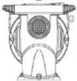
C
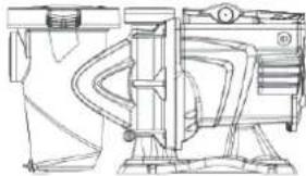
natural_image
Technical line drawing of a mechanical device with internal components and mounting base (no text or symbols)D
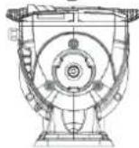
E
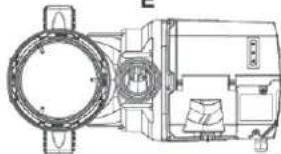
natural_image
Technical line drawing of a mechanical assembly with circular components and housing (no text or symbols)Figure 2
natural_image
Two black-and-white icons: one with hands holding a crystal, the other with a wine glass (no text or symbols)• MANIPULER AVEC SOIN
- FRAGILE

natural_image
Two black-and-white icons: one with two upward arrows and another with an umbrella (no text or symbols)HAUT
• GARDER LOIN DE L'EAU
FRANÇAIS
natural_image
Technical line drawing of a mechanical assembly with a red X mark indicating a disassembled component (no text or symbols present)2.1 Raccords hydrauliques
natural_image
Technical line drawing of a mechanical device with internal components and exploded view (no text or symbols)Figure 3
FRANÇAIS
natural_image
Technical line drawing of a mechanical component with no visible text or symbols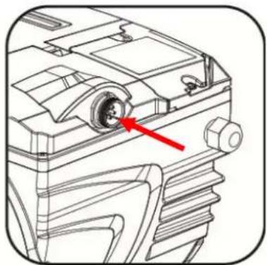
natural_image
Technical line drawing of a mechanical component with a red arrow pointing to a circular feature (no text or symbols present)Figure 4a
Figure 7b
Figure 14
Figure 24

Figure 26
Figure 29
Figure 31
Figure 33
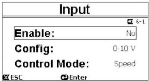
Figure 34
Figure 36
Figure 37
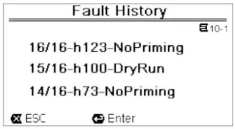
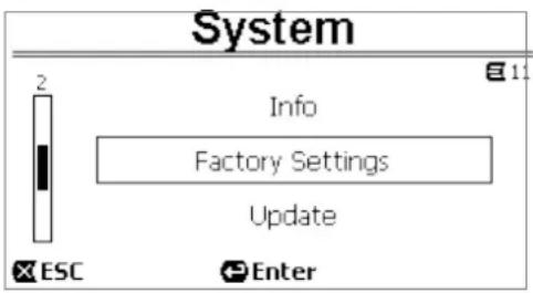
Figure 40
Ladson, SC 29456, USA
ESPAÑOL
ÍNDICE
1 GENERALIDADES......66
natural_image
Two black-and-white illustrations showing a person diving into water and another lying on the surface, both without any text or symbols.
natural_image
Two black-and-white icons: one with hands holding a crystal, the other with a trophy and broken glass (no text or symbols)• MANEJAR CON CUIDADO
- FRÁGIL

natural_image
Two black-and-white icons: one with two upward arrows and another with an umbrella (no text or symbols)• ESTE LADO ARRIBA
natural_image
Technical illustration of a mechanical assembly with red X marks indicating a disassembled component (no text or symbols present)natural_image
Technical illustration of a mechanical device with exploded and assembled views, labeled 'Ilustración 3' (no text or symbols on the diagram itself)ESPAÑOL

natural_image
Technical line drawing of a mechanical device with no visible text or symbols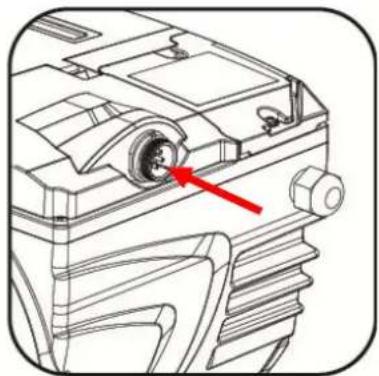
natural_image
Technical line drawing of a mechanical component with a red arrow pointing to a circular feature (no text or symbols present)Ilustración 4a
Ilustración 7b
ESPAÑOL
Ilustración 8
Ilustración 13
Figure 24
Ilustración 28

Ilustración 29
Ilustración 31
Ilustración 33
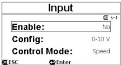
Ilustración 34
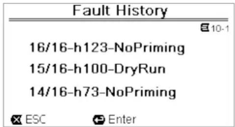
6.2.11 Sistema
Ilustración 40
Ladson, SC 29456, USA
13. REPLACEMENT PARTS - PIÈCES DE RECHANGE - PARTES DE RECAMBIO
13.1 Parts diagram – Pièces diagramme - Diagrama de partes
E.SWIM 150

USE ONLY DAB GENUINE REPLACEMENT PARTS
UTILISEZ UNIQUEMENT DES PIÈCES
D'ORIGINE DAB
UTILICE SÓLO PIEZAS ORIGINALES DAB
E.SWIM 300
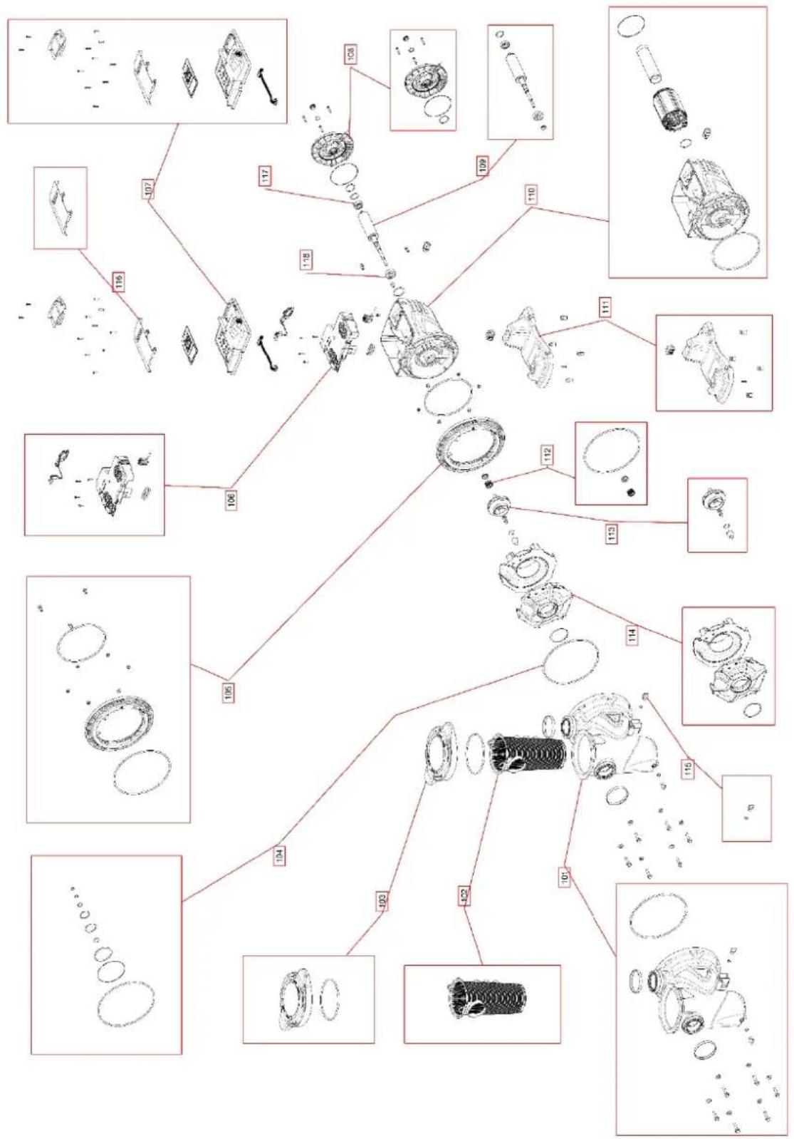
flowchart
graph TD
    A["Component 107"] --> B["Component 117"]
    B --> C["Component 118"]
    C --> D["Component 119"]
    D --> E["Component 110"]
    E --> F["Component 111"]
    F --> G["Component 112"]
    G --> H["Component 113"]
    H --> I["Component 114"]
    I --> J["Component 115"]
    J --> K["Component 101"]
    K --> L["Component 102"]
    L --> M["Component 103"]
    M --> N["Component 104"]
    N --> O["Component 106"]
    O --> P["Component 107"]
    P --> Q["Final Component"]

    style A fill:#f9f,stroke:#333
    style Q fill:#f9f,stroke:#333
USE ONLY DAB GENUINE REPLACEMENT PARTS UTILISEZ UNIQUEMENT DES PIÈCES D'ORIGINE DAB UTILICE SÓLO PIEZAS ORIGINALES DAB
E.SWIM 150
| Reference Designator | Number Description Quantity | ||
| 1 | SP00002548 | PUMP BODY NPT | 1 |
| 2 | SP00005931 | FILTER | 1 |
| 3 | R00010358 | NUT RING | 1 |
| 4 | R00010367 | DISCHARGE CAP | 1 |
| 5 | SP00006672 | INTERNAL VOLUTE | 1 |
| 6 | SP00002539 | KIT O-RINGS | 1 |
| 7 | SP00002540 | IMPELLER ∅78 | 1 |
| 8 | SP00007125 | SHAFT SEAL D.15 | 1 |
| 9 | SP00002541 | MAIN PCB E-SWIM | 1 |
| 10 | SP00002542 | LOW VOLTAGE COMPLETE BOARD | 1 |
| 10 | SP00005999 | LOW VOLTAGE COMPLETE BOARD US SVRS | 1 |
| 11 | SP00002543 | POOL ROTOR W SHAFT H100 | 1 |
| 12 | R00010356 | BALL BEARINGS 6302-2RSH | 1 |
| 13 | R00010751 | BALL BEARING 6202-2RSH | 1 |
| 14 | SP00002544 | MOTOR COVER | 1 |
| 15 | SP00002545 | STATOR HOUSING + WOUD STATOR | 1 |
| 16 | R00010366 | BASE | 1 |
| 90 | SP00003548 | E-SWIM USER PANEL COVER | 1 |
E.SWIM 300
| Reference Designator | Number Description | Quantity | |
| 1 | SP00006975 | PUMP BODY ASS.Y EURO-PRO-E_SWIM | 1 |
| 2 | R00010389 | FILTER | 1 |
| 3 | SP00005920 | FILTER COVER EUROSWIM 150-300-E-SWIM 300 | 1 |
| 4 | R00010367 | DISCHARGE CAP | 1 |
| 5 | SP00006673 | INTERNAL VOLUTE E-SWIM 300 | 1 |
| 6 | SP00005922 | KIT O-RINGS E-SWIM 300 | 1 |
| 7 | SP00005923 | IMPELLER ∅78 | 1 |
| 8 | SP00007166 | SHAFT SEAL D.15 E-SWIM BT | 1 |
| 9 | SP00005925 | MAIN PCB E-SWIM 300 | 1 |
| 10 | SP00002542 | LOW VOLTAGE COMPLETE BOARD | 1 |
| 11 | SP00005926 | POOL ROTOR W SHAFT H120 | 1 |
| 12 | R00010356 | BALL BEARINGS 6302-2RSH | 1 |
| 13 | R00010751 | BALL BEARING 6202-2RSH | 1 |
| 14 | SP00002544 | MOTOR COVER | 1 |
| 15 | SP00005927 | STATOR HOUSING + WOUND STATOR H120 | 1 |
| 16 | R00010366 | BASE | 1 |
| 17 | SP00003548 | E-SWIM USER PANEL COVER | 1 |
| 18 | SP00005928 | FLANGE E-SWIM 300 | 1 |
DAB PUMPS LTD.
6 Gilbert Court
Newcomen Way
Severalls Business Park
Colchester
Essex
C04 9WN - UK
salesuk@dwtgroup.com
Tel. +44 0333 777 5010
DAB PUMPS BV
'tHofveld 6 C1
info.belgium@dwtgroup.com
Tel. +32 2 4668353
DAB PUMPS INC.
3226 Benchmark Drive
Ladson, SC 29456 - USA
info.usa@dwtgroup.com
Tel. 1-843-797-5002
Fax 1-843-797-3366
000 DAB PUMPS
Novgorodskaya str. 1, block G
office 308, 127247, Moscow - Russia
info.russia@dwtgroup.com
Tel. +7 495 122 0035
Fax +7 495 122 0036
DAB PUMPS POLAND SP. z.o.o.
No.40 Kaituo Road, Qingdao Economic &
Technological Development Zone
Qingdao City, Shandong Province - China
PC: 266500
sales.cn@dwtgroup.com
Tel. +86 400 186 8280
Fax +86 53286812210
DAB PUMPS IBERICA S.L.
Calle Verano 18-20-22
28850 - Torrejón de Ardoz - Madrid
Spain
Info.spain@dwtgroup.com
Tel. +34 91 6569545
Fax: + 34 91 6569676
DAB PUMPS B.V.
Twenty One industrial Estate,
16 Purlin Street, Unit B, Warehouse 4
Olifantsfontein - 1666 - South Africa
info.sa@dwtgroup.com
Tel. +27 12 361 3997
DAB PUMPS GmbH
Am Nordpark 3
41069 Mönchengladbach, Germany
info.germany@dwtgroup.com
Tel. +49 2161 47 388 0
Fax +49 2161 47 388 36
DAB PUMPS HUNGARY KFT.
H-8800
Nagykanizsa, Buda Ernő u.5
Hungary
Tel. +36 93501700
426 South Gippsland Hwy,
Dandenong South VIC 3175 – Australia
info.oceania@dwtgroup.com
Tel. +61 1300 373 677

WATER•TECHNOLOGY
DAB PUMPS S.p.A.
Via M. Polo, 14 - 35035 Mestrino (PD) - Italy
Tel. +39 049 5125000 - Fax +39 049 5125950
www.dabpumps.com

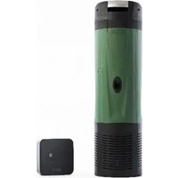
- IMPORTANT WARNINGS AND SAFETY RECOMMENDATIONS....2
- GENERAL 4
- INSTALLATION....6
- THE OPERATOR PANEL....11
- COMMISSIONING....13
- SWITCHING ON AND USING THE PUMP....14
- SELECTING THE PREFERRED MODES (MENU)....17
- PROTECTION SYSTEMS - LOCKS (FAULT)......27
- FACTORY SETTINGS....27
- TROUBLESHOOTING 29
- MAINTENANCE 30
- DISPOSAL 30
- GUARANTEE....30
- PARTS LISTING....95
- ENGLISH
- KEY
- IMPORTANT WARNINGS AND SAFETY RECOMMENDATIONS
- GENERAL RISK FACTORS
- INSTALLATION AND MAINTENANCE BY QUALIFIED PERSONNEL
- USE ONLY BY COMPETENT PERSONS
- MECHANICAL SAFETY
- NEVER LET THE PUMP RUN WITHOUT WATER.
- ELECTRICAL SAFETY
- RISKS LINKED TO HEATING
- TYPES OF PUMPED LIQUIDS ALLOWED
- DO NOT USE THE PUMP WITH LIQUIDS WITH DIFFERENT CHARACTERISTICS!
- SPECIFIC RISKS FOR SWIMMING POOLS, BATHING POOLS AND SIMILAR
- WARNING- To reduce the risk of entrapment:
- Dangerous pressures
- RESPONSIBILITY
- GENERAL
- Description
- Technical characteristics
- SVRS Notes (Only applicable to model SVRS)
- INSTALLATION
- UNPACKING INSTRUCTION
- Hydraulic connections
- Pipe Sizing Chart
- Plumbing
- Electrical connection to the supply line
- Electrical connections for auxiliary inputs and outputs
- Keyboard and Display
- Description of the elements:
- Main page of the display (homepage)
- COMMISSIONING
- Priming
- Guided configuration (WIZARD)
- SWITCHING ON AND USING THE PUMP
- Operating mode
- Regulating modes
- E.SWIM 300
- Command modes
- Rapid starting and stopping of the pump ("Manual" mode).
- Check well all the IMPORTANT SAFETY WARNINGS AND RECOMMENDATIONS.
- Rapid changing of the setpoint and of the pre-set parameters
- Advanced use ("Auto" mode)
- SELECTING THE PREFERRED MODES (MENU)
- Menu access and navigation
- The page contains these elements:
- Access to a sub-menu
- Changing a parameter in the menu
- Menu structure
- Settings
- WIZARD (loaded from the menu)
- Languages
- Day & Time
- Unit of Measure
- Pump Limits
- SVRS (only for model with SVRS)
- Screen adjustment
- Password
- Set Points 1-4
- Set Points 5-8
- Quick Clean
- Timers
- Timer Settings
- Timer daily summary
- External Control
- Configuration of the Inputs
- Configuration of the Outputs
- Priming
- Antifreeze (Protection against water freezing in the pump)
- Anti-Lock (Protection against mechanical blocking of the pump)
- Fault History
- System
- PROTECTION SYSTEMS - LOCKS (FAULT)
- Manual reset of error conditions
- Automatic reset of error conditions
- Viewing the block history
- FACTORY SETTINGS
- Restoring the factory settings
- TROUBLESHOOTING
- General problems
- SVRS problems
- Suction Blockage
- SVRS Blockage:
- MAINTENANCE
- DISPOSAL
- GUARANTEE
- FOR CUSTOMER SERVICE IN ALL U.S. & CANADA AREAS CALL:
- FRANÇAIS
- SOMMAIRE
- GÉNÉRALITÉS 34
- Raccords hydrauliques
- ESPAÑOL
- ÍNDICE
- GENERALIDADES......66
- Sistema
- REPLACEMENT PARTS - PIÈCES DE RECHANGE - PARTES DE RECAMBIO
- Parts diagram – Pièces diagramme - Diagrama de partes
- DAB PUMPS LTD.
- DAB PUMPS BV
- DAB PUMPS INC.
- DAB PUMPS
- DAB PUMPS POLAND SP. z.o.o.
- DAB PUMPS IBERICA S.L.
- DAB PUMPS B.V.
- DAB PUMPS GmbH
- DAB PUMPS HUNGARY KFT.
- DAB PUMPS S.p.A.
Brand : DAB
Model : ESwim
Category : Pump