
WGen18000DFc - Generator WESTINGHOUSE - Free user manual and instructions
Find the device manual for free WGen18000DFc WESTINGHOUSE in PDF.

User questions about WGen18000DFc WESTINGHOUSE
0 question about this device. Answer the ones you know or ask your own.
Ask a new question about this device
Download the instructions for your Generator in PDF format for free! Find your manual WGen18000DFc - WESTINGHOUSE and take your electronic device back in hand. On this page are published all the documents necessary for the use of your device. WGen18000DFc by WESTINGHOUSE.
USER MANUAL WGen18000DFc WESTINGHOUSE
natural_image
Blue circular icon with a white crown symbol (no text or numbers)User Manual
WGen12000DFc
natural_image
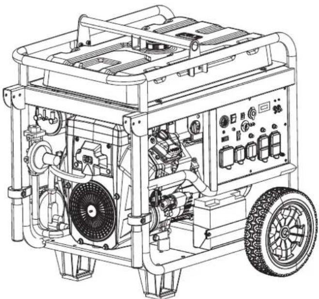
Technical line drawing of a portable gas generator with visible motors, wheels, and control panel (no text or labels)TABLE OF CONTENTS
INTRODUCTION
DISCLAIMERS....2
ALL RIGHTS RESERVED....2
SPECIFICATIONS....3
SAFETY
SAFETY DEFINITIONS....4
SAFETY SYMBOLS....4
SAFETY INSTRUCTIONS....5
CO SENSOR....8
SAFETY LABELS AND DECALS....9
COMPONENTS
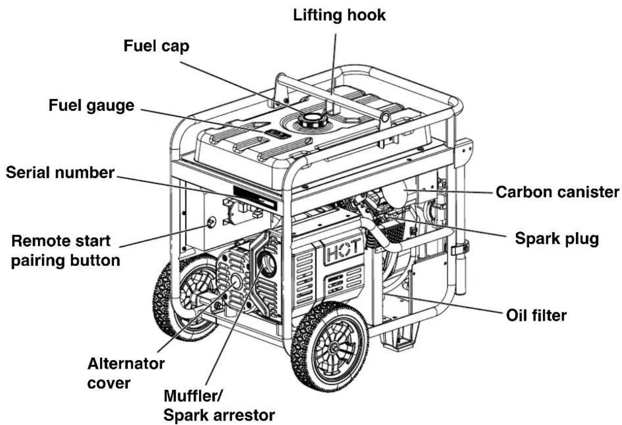
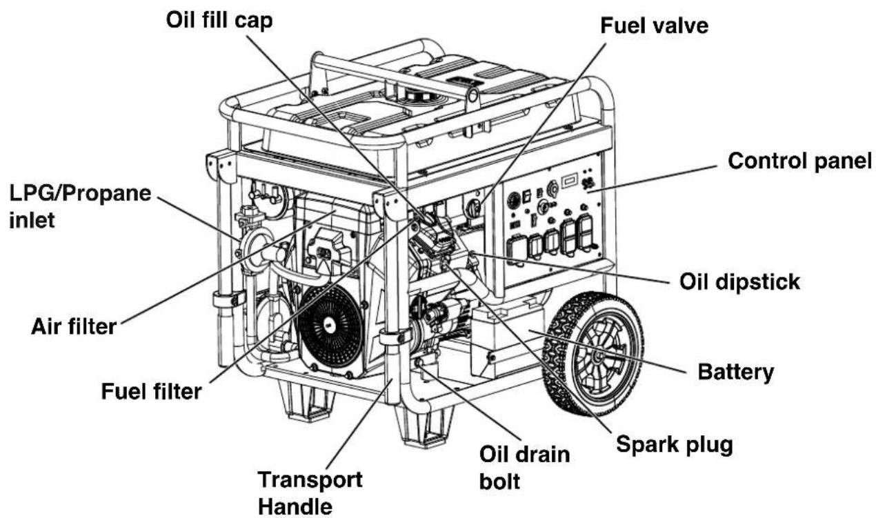
GENERATOR COMPONENTS....10
CONTROL PANEL COMPONENTS....11
DATA CENTER....12
MAINTENANCE REMINDERS ....12
ASSEMBLY
CARTON CONTENTS 13
INSTALL WHEELS AND LIFTING BRACKET....13
INITIAL OIL FILL....14
BATTERY INSTALLATION....14
FUEL....14
CONNECT AN LPG/PROPANE TANK....15
OPERATION
GENERATOR LOCATION....17
GROUNDING....17
HIGH ALTITUDE OPERATION....18
REMOTE START....18
FUEL SELECTOR SWITCH 19
BREAK-IN PERIOD 19
LOW IDLE....19
BEFORE STARTING THE GENERATOR....19
STARTING THE ENGINE: GASOLINE....19
STARTING THE ENGINE: PROPANE....20
SWITCHING FUEL SOURCES....20
STOPPING THE ENGINE....20
FREQUENCY OF USE 20
AC CIRCUIT BREAKERS ....20
POWER MANAGEMENT....21
EXTENSION CORDS 22
ST SWITCH....22
TRANSPORTING....23
LIFTING HOOK....23
MAINTENANCE
MAINTENANCE SCHEDULE 24
MAINTENANCE REPLACEMENT PARTS....24
AIR FILTER MAINTENANCE....24
ENGINE OIL LEVEL CHECK....24
ENGINE OIL CHANGE ....25
SPARK PLUG MAINTENANCE....26
SPARK ARRESTOR SERVICE....26
FUEL FILTER....26
BATTERY MAINTENANCE....27
BATTERY REPLACEMENT....27
STORAGE....27
VALVE CLEARANCE....28
TROUBLESHOOTING
TROUBLESHOOTING....29
SCHEMATICS
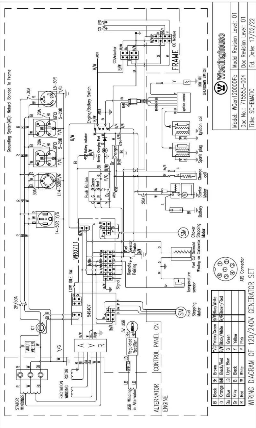
SCHEMATICS....31
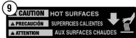
⚠ WARNING: Operating, servicing, and maintaining this equipment can expose you to chemicals including engine exhaust, carbon monoxide, phthalates, and lead, which are known to the State of California to cause cancer and birth defects or other reproductive harm. To minimize exposure, avoid breathing exhaust, and wear gloves or wash your hands frequently when servicing this equipment. For more information go to www.P65warnings.ca.gov.
DISCLAIMERS
All information, illustrations, and specifications in this manual were in effect at the time of publishing. The illustrations used in this manual are intended as representative reference views only. We reserve the right to make any specification or design change without notice.
ALL RIGHTS RESERVED
All rights reserved. No reproduction allowed in any form without written permission from Westinghouse Outdoor Power Equipment, LLC.
▲ DANGER

Read this manual before using or performing maintenance on this product. Failure to follow the instructions and safety precautions in this manual can result in serious injury or death.
SAVE THESE INSTRUCTIONS
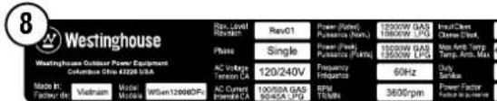
| SPECIFICATIONS | |
| Running Watts: | 12,000 Gas / 10,800 LPG |
| Peak Watts: | 15,000 Gas / 13,500 LPG |
| Rated Voltage: | 120/240V |
| Rated frequency: | 60 Hz @ 3600 RPM |
| Phase: | Single phase |
| Total Harmonic Distortion: | ≤ 5% |
| Engine Displacement: | 713 cc |
| Starting Type: | Recoil, Electric Start, Remote |
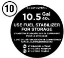
| Fuel Capacity: | 10.5 Gallons (40 Liters) |
| Fuel Type: | • Unleaded gasoline 87–93 octane* • HD-5 Propane |
| Oil Capacity: | 1.7 US Quart (1.6 Liter) |
| Oil Type: | SAE 10W-30 |
| Spark Plug: | 97110 (5357) |
| Spark Plug Gap: | 0.024 – 0.032 in. (0.60 – 0.80 mm) |
| Valve Intake Clearance: | 0.0031 – 0.0047 in. (0.08 – 0.12 mm) |
| Valve Exhaust Clearance: | 0.0051 – 0.0067 in. (0.13 – 0.17 mm) |
| AC Grounding System: | Bonded to frame |
| Voltage Regulator: | AVR |
| Alternator Type: | Brushed |
| Maximum Ambient Temperature: | 104°F (40°C) |
| Certifications: | • EPA • CARB |
*Ethanol content of 10% or less. DO NOT use E15 or E85.
UPDATES
The latest User Manual for your Westinghouse generator can be found under our support tab. https://westinghouseoutdoorpower.com/pages/manuals
Or scan the following QR code with your smartphone camera to be directed to the link.

NOTICE
This product is designed and rated for continuous operation at ambient temperatures up to 104^ F ( 40^ C). If needed, this product can be operated at temperatures ranging from 5^ F ( 15^ C)– 122^ F ( 50^ C) for short periods. If the product is exposed to temperatures outside of this range during storage, it should be brought back within this range before operation. This product must always be operated outdoors in a well-ventilated area and far away from doors, windows, and other vents.
Maximum wattage and current are subject to and limited by such factors as fuel BTU content, ambient temperature, altitude, engine conditions, etc. Maximum power decreases about 3.5% for each 1,000 feet above sea level, and will also decrease about 1% for each 10°F (6°C) above 60°F (16°C) ambient temperature.
PRODUCT REGISTRATION
For trouble-free warranty coverage, it is important to register your Westinghouse generator.
You can register by:
- Completing and mailing the product registration card included in the carton.
- Registering your product online at: https://westinghouseoutdoorpower.com/pages/warranty-registration
- Scan the following QR code with your smartphone camera to be directed to the mobile registration link.

- Sending the following product information to:
Westinghouse Outdoor Power
Warranty registration
777 Manor Park Drive
Columbus, OH 43228
For Your Records
Date of Purchase: ____
Model Number: ____
Serial Number:
Place of Purchase: ____
IMPORTANT: Keep your purchase receipt for trouble-free warranty coverage.
SAFETY DEFINITIONS
The words DANGER, WARNING, CAUTION, and NOTICE are used throughout this manual to highlight important information. Make sure that the meanings of this safety information is known to all who operate, perform maintenance on, or are near the generator.

This safety alert symbol appears with most safety statements. It means attention, be alert, your safety is involved! Please read and abide by the message that follows the safety alerts symbol.
▲ DANGER
Indicates a hazardous situation which, if not avoided, will result in death or serious injury.
▲ WARNING
Indicates a hazardous situation which, if not avoided, could result in death or serious injury.
▲ CAUTION
Indicates a hazardous situation which, if not avoided, could result in minor or moderate injury.
NOTICE
Indicates a situation which can cause damage to the generator, personal property, and/or the environment, or cause the equipment to operate improperly.
Note: Indicates a procedure, practice or condition that should be followed for the generator to function in the manner intended.
SAFETY SYMBOLS
Follow all safety information contained in this manual and on the generator.
| Symbol Description | |
 | Safety Alert Symbol |
 | Electrocution Hazard |
 | Asphyxiation Hazard |
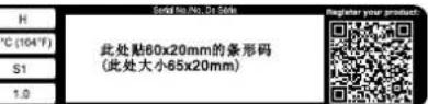
 | Burn Hazard. Do not touch hot surfaces. |
 | Electrical Shock Hazard |
 | Fire Hazard |
 | Maintain Safe Distance |
 | Lifting Hazard |
 | Read Manufacturer's Instructions |
 | Do Not Operate in Wet Conditions |
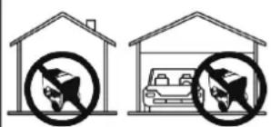
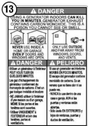
! DANGER
Using a generator indoors CAN KILL YOU IN MINUTES. Generator exhaust contains carbon monoxide. This is a poison you cannot see or smell.

NEVER use inside a home or garage, EVEN IF doors and windows are open.
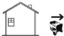
Only use OUTSIDE and far away from windows, doors, and vents.
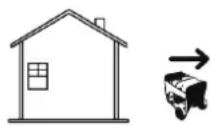
CORRECT USE
Example location to reduce risk of carbon monoxide poisoning ONLY use outside and downwind, far away from windows, doors and vents. Direct exhaust away from occupied spaces
flowchart
graph TD
    A["Location to reduce risk of carbon monoxide poisoning"] --> B["Exhaust (CO)"]
    B --> C["Only use OUTSIDE and FAR AWAY from windows, doors, and vents."]
    C --> D["CO Detectors in living areas"]
    D --> E["Living Area"]
    E --> F["Basement Crawlspace"]
    F --> G["Entryway Porch Mud Room"]
    G --> H["Garage"]
    H --> I["INCORRECT USE"]
    I --> J["Do not operate in any of the following locations: Near any door, window, or vent"]
    J --> K["Garage"]
    J --> L["Basement"]
    J --> M["Crawl Space"]
    J --> N["Living Area"]
    J --> O["Attic"]
    J --> P["Entry Way"]
    J --> Q["Porch"]
    J --> R["Mudroom"]
NOTICE
Install battery-powered carbon monoxide detectors or plug-in carbon monoxide detectors with battery back-up in living areas.
▲ DANGER
Fire and electrocution hazard. Do not connect to a building's electrical system unless the generator and transfer switch have been properly installed and the electrical output has been verified by a qualified electrician. The connection must isolate the generator power from utility power and must comply with all applicable laws and electrical codes.
▲ DANGER
Electrocution hazard. Never use the generator in a location that is wet or damp. Never expose the generator to rain, snow, water spray, or standing water while in use. Protect the generator from all hazardous weather conditions. Moisture or ice can cause a short circuit or other malfunction in the electrical circuit.
GENERAL SAFETY PRECAUTIONS
- Never use the generator to power medical support equipment.
- Do not operate the generator when you are tired or under the influence of drugs, alcohol, or medication.
- Do not use generator with electrical cords which are worn, frayed, bare, or otherwise damaged.
- All electrical tools and appliances operated from this generator must be properly grounded by use of a third wire or be double-insulated.
- When this generator is used to supply a building wiring system the generator must be installed by a qualified electrician and connected to a transfer switch as a separately derived system in accordance with NFPA 70, National Electrical Code.
- If you begin to feel sick, dizzy, or weak while using the generator, move to fresh air IMMEDIATELY. See a doctor, as you can have carbon monoxide poisoning.
- Only use OUTSIDE and far away from windows, doors, and vents as recommended by the US Department of Health and Human Services Centers for Disease Control and Prevention. Your specific home and/or wind conditions may require additional distance.
- While operating and storing, keep at least five feet of clearance on all sides of the generator, including overhead. Allow the generator to cool a minimum of 30 minutes before storage. Heat created by the muffler and exhaust gases could be hot enough to cause serious burns and/or ignite combustible objects.
- Do not touch the muffler or engine. They are very HOT and will cause severe burns. Do not put body parts or any flammable or combustible materials in the direct path of the exhaust.
- Always remove any tools or other service equipment used during maintenance away from the generator before operating.
- Avoid skin contact with engine oil or gasoline. Wear protective clothing and equipment. Wash all exposed skin with soap and water.
FUEL SAFETY
- Store fuel in a container approved for gasoline.
- Do not smoke when filling the generator with gasoline.
- Do not allow the generator's gas tank to overflow when filling.
- Shut down the engine and allow it to cool for two minutes before adding gasoline or oil to the generator.
- Never remove the fuel cap when the generator is running. Shut off the engine and allow the unit to cool at least two minutes. Remove the fuel cap slowly to release pressure, keep fuel from escaping around the cap, and to avoid the heat from the muffler igniting fuel vapors. Tighten the fuel cap securely after refueling.
- Wipe spilled fuel from the unit.
- Never attempt to burn off spilled fuel.
- Never overfill the fuel tank. Leave room for fuel to expand. Overfilling the fuel tank can result in a sudden overflow of gasoline and result in spilled gasoline coming in contact with HOT surfaces.
- Spilled fuel can ignite. If fuel is spilled on the generator, wipe up any spills immediately. Dispose of rag properly. Allow area of spilled fuel to dry before operating the generator.
- Wear eye protection while refueling.
- Never use gasoline as a cleaning agent.
- Store any containers containing gasoline or LPG/propane in a well-ventilated area, away from any combustibles or source of ignition.
Fire and explosion hazard. Gasoline and LPG/propane are highly explosive and flammable and can cause severe burns or death.
- In case of a gas fire, do not attempt to extinguish the flame if the fuel tank valve is in the ON position. Introducing an extinguisher to a generator with an open fuel valve could create an explosion hazard.
- Gas has a distinctive odor, this will help detect potential leaks quickly.
• Gas vapors can cause a fire if ignited. - Gasoline is a skin irritant and needs to be cleaned up immediately if it comes in contact with the skin.
LIQUID PETROLEUM GAS (LPG/PROPANE)
WARNING
Fire and explosion hazard. Never use a gas container, LPG/propane connector hose, LPG/propane tank or any other fuel item that appears to be damaged.
▲ CAUTION
Fire and explosion hazard. Only use approved LPG/propane tanks with an Overfilling Prevention Device (OPD) valve. Always keep the tank in a vertical position with the valve on top and placed at ground level on a flat surface. Do not allow tanks to be near any heat source. When transporting and storing, turn the propane tank valve to the fully closed position and disconnect the tank. Make sure to always cover the generator inlet and tank outlet with protective plastic caps.
• LPG/Propane is highly flammable and explosive.
- Flammable gas under pressure can cause a fire or explosion if ignited.
- LPG/Propane can settle in low places because it is heavier than air.
- LPG/Propane has a distinctive odor added to help detect potential leaks.
• Always keep a LPG/Propane tank in an upright position.
- When exchanging LPG/propane tanks, be sure the tank valve is the same type.
- In case of a LPG/propane fire, do not attempt to extinguish unless the fuel supply can be shut off safely.
- LPG/propane will burn the skin. Prevent skin contact at all times.
- Keep the propane tank away from the generator exhaust.
- A step down regulator is required when using LPG/propane tanks over 100 gallons. The pressure as measured at the regulator mounted to the generator must be 7" to 14" of water column.
- Large (500–1000 gallon) LPG/propane tanks will require a certified plumber to install the fuel line to the generator and the loose regulator is not used (the regulator that is attached to the fuel tank). The pressure as measured at the regulator mounted to the generator must be 7" to 14" of water column. A certified plumber must ensure that the pressure is correct or install a step down regulator if needed.
▲ WARNING
Fire and explosion hazard. If there is a strong smell of propane while operating the generator, fully close the LPG/propane tank valve immediately. Once the propane is off, use soapy water to check for leaks on the hose and connections on the tank valve and the generator. Do not smoke or light a cigarette or check for leaks using any open flame source such as a match or lighter. If a leak is found, contact a qualified technician to inspect and repair the LPG/propane system before using the generator.
When starting the generator:
- Make sure that the fuel cap, air filter, spark plug, fuel lines, and exhaust system are properly in place.
- If you spill any gasoline on the tank, allow it to fully evaporate before operating.
- Make sure the generator and LPG/propane tank are on a flat surface before operating.
- If there is a propane odor do not start the unit because there may be a potential leak. Never place a LPG/propane tank near the engine exhaust.
When transporting or servicing the generator:
- Make sure the LPG/propane tank and LPG/propane hose are not attached to the generator.
- Disconnect the spark boot to prevent accidental starting.
When storing the generator:
- Store away from sparks, open flames, pilot lights, heat, and other sources of ignition.
- Do not store gas or a LPG/propane tank near furnaces, water heaters, or any other appliances that produce heat or have automatic ignitions.
CO SENSOR
The CO Sensor monitors for the accumulation of poisonous carbon monoxide gas around the generator when the engine is running. If increasing levels of CO gas are detected, the CO Sensor automatically shuts down the engine.
The CO Sensor will also detect the accumulation of carbon monoxide from other fuel burning sources used in the area of operation. For example, if the exhaust of fuel burning tools is pointed at a CO Sensor-equipped generator, a shut-off may be initiated due to rising CO levels. This is not an error. Hazardous carbon monoxide has been detected. Move and redirect any additional fuel burning sources to dissipate carbon monoxide away from personnel and occupied buildings.
Note: Remote start-equipped generators must be restarted with the START/STOP button on the control panel after an automatic shut-down occurs.
Generators are intended to be used outdoors, far from occupied buildings and the exhaust pointed away from personnel and buildings. If misused and operated in a location that results in the accumulation of CO, like in a partially enclosed area, the CO Sensor shuts off the engine, notifies the user with a RED indicator light, and directs the user to read the Action Label for steps to take. The CO Sensor DOES NOT replace carbon monoxide alarms. Install battery-powered carbon monoxide alarm(s) in your home.
WARNING
Automatic shutoff accompanied with a flashing RED light in the CO Sensor portion of the control panel is an indication that the generator was improperly located. If you start to feel sick, dizzy, weak, or carbon monoxide detectors in your home indicate an alarm, get to fresh air immediately. Call emergency services. You may have carbon monoxide poisoning.
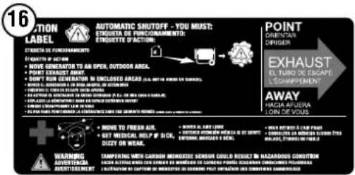
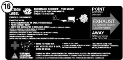
ACTION LABEL
CONTROL PANEL CO AUTO-SHUTOFF
CARBON MONOXIDE AUTO-SHUTOFF

SERVICE GENERATOR
REALICE UN SERVICIO
DEL GENERADOR

AUTOMATIC SHUTOFF
SEE MANUAL
CORTE AUTOMÁTICO
LEER EL MANUAL
CO SENSOR INDICATOR LIGHTS
Color Description
| RED | Carbon monoxide accumulated around the generator. After shut-off, the RED indicator light in the CO Sensor area of the control panel will flash to provide notification that the generator was shut-off due to an accumulating CO hazard. The RED light will flash for at least five minutes after a CO shut-off.Move the generator to an open, outdoor area far away from occupied spaces with exhaust pointed away. Once relocated to a safe area, the generator can be restarted. Introduce fresh air and ventilate the area where the generator had shut down. |
| YELLOW | A CO sensor system fault occurred. When a system fault occurs, the generator is automatically shut down and the YELLOW indicator light in the CO auto-shutoff area of the control panel will flash to provide notification that a fault has occurred. The YELLOW light will flash for at least five minutes after a fault. The generator can be re-started, but may continue to shutoff. A CO sensor fault can only be diagnosed and repaired by an authorized Westinghouse service center. |
ACTION
LABEL
ETIQUETA DE FUNCIONAMIENTO
ÉTIQUETTE D'ACTION
• MOVE GENERATOR TO AN OPEN OUTDOOR AREA
• MOVE GENERATION TO A
• POINT EXHAUST AWAY
• DON'T RUN GENERATOR IN ENCLOSED AREAS (E.G. NOT IN HOUSE OR GARAGE)
• MOVER EL GENERADOR A UN ÁREA AMERTA, EN EXTERIORES
- ORIENTAR EL TUBO DE ESCAPE HACIA AFUERA
- NO ACTIVAR EL GENERADOR EN ÁREAS CERRADAS (P. EJ.: EN UNA CASA O GARAJE)
- DÉPLACER LA GÉNÉRATRICE DANS UN ESPACE EXTÉRIEUR OUVERT
• DIRIGER L'ECHAPPEMENT LOIN DE VOUS
• NE PAS FAIRE FONCTOINIER LA GENERATRICE DANS DES ENDROITS FERMES (DOMME DANS LA HANSON OU LE CAVAIRE)


• MOVE TO FRESH AIR.
• GET MEDICAL HELP IF SICK, DIZZY OR WEAK.
TAMPERING WITH CARBON MO HACER ALTERACIONES CON SENSOR DE L'ALTÉRATION DE CAPTEUR DE MONOXY
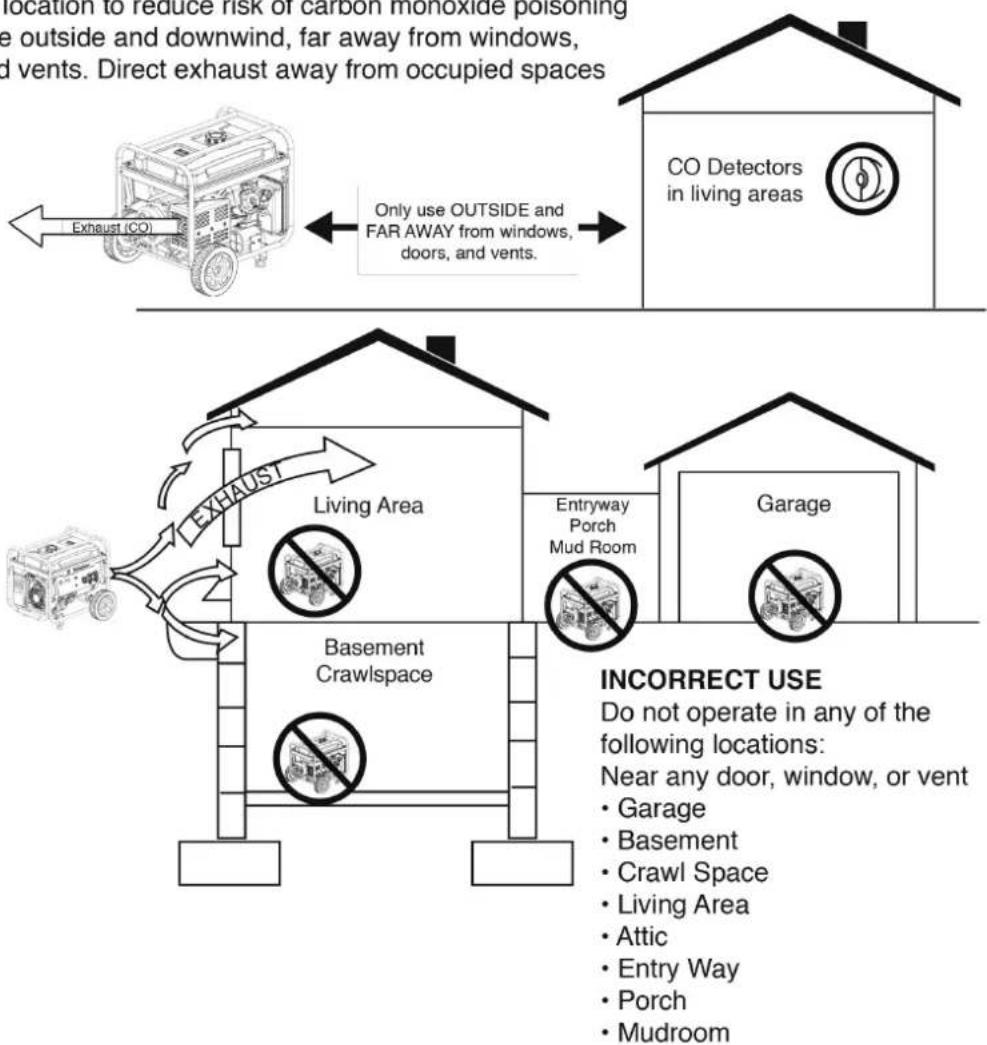
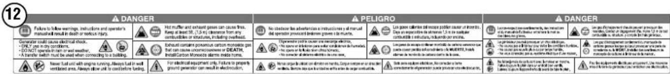
SAFETY LABELS AND DECALS
FUEL SOURCE CANNOT BE SWITCHED WHILE RUNNING, SHUT DOWN, SWITCH FUEL SOURCE, AND RESTART TO AVOID DAMAGING GENEARTOR. LA FUENTE DE COMBUSTIBLE NO PUEDE SER CONMUTADA MIENTRAS FUNCIONA, APAGUE, APAGUE LA FUENTE DE COMBUSTI- BLE Y REINCIE PARA EVITAR EL GENEARTOR DANADO.
LA SOURCE DE CARBURANT NE PEUT PAS ÊTRE COMMUTÉE PENDANT LE FONCTIONNEMENT, FERMEZ, COMMUTEZ LA SOURCE DE CARBURANT ET REDÉMARREZ POUR ÉVITER D'ENDOMMAGER LE GÉNÉTATEUR.


GENERATOR COMPONENTS
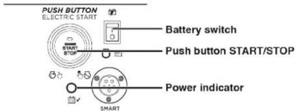
CONTROL PANEL
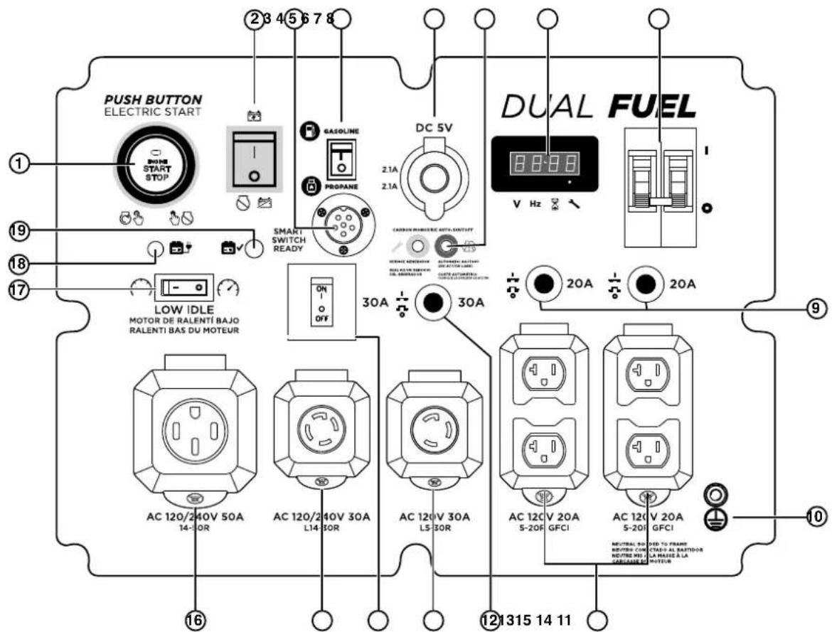
- Push-Button START/STOP: Push once to automatically start the engine. Push again to stop the engine.
- Battery Switch: Turns battery ON and OFF. Must be ON before electric or remote start.
- Smart Switch Outlet: Connects the Westinghouse ST Switch (sold separately) to the control panel.
- Fuel Selector Switch: Used to select gas or propane operation.
- USB Ports: Two-port 5V/2.1A USB outlet. Accepts Type A USB plugs.
- CO Sensor indicator lights: The CO Sensor monitors for the accumulation of poisonous carbon monoxide gas. If increasing levels of CO gas are detected, the CO Sensor automatically shuts down the engine.
- Data Center: Displays voltage, frequency, total hour meter, and run/maintenance timer.
- Main Circuit Breaker: The main circuit breaker controls total output of all outlets to protect the generator from overload or short circuit.
- 20 Amp AC Circuit Breakers: Circuit breakers limits the current that can be delivered through each NEMA 5-20R receptacle to 20 Amps.
-
Ground Terminal: The ground terminal is used to externally ground the generator.
-
120-Volt AC, 20-Amp NEMA 5-20R GFCI Receptacles: Each receptacle is capable of carrying a maximum of 20 amps on a single receptacle or a combination of both receptacles.
- 30 Amp AC Circuit Breaker: Circuit breaker limits the current that can be delivered through the NEMA L14-30R receptacle to 30 amps.
- 120-Volt AC, 30-Amp NEMA L5-30R Receptacle: Receptacle can supply a maximum of 30 Amps.
- 30 Amp AC Circuit Breaker: Circuit breaker limits the current that can be delivered through the NEMA L5-30R receptacle to 30 amps.
- 120/240-Volt AC, 30-Amp NEMA L14-30R Receptacle: Receptacle can supply either 120V or 240V up to 30 amps.
- 120/240-Volt AC, 50-Amp NEMA 14-50R Receptacle: Receptacle can supply either 120V or 240V up to 50 amps.
- Low Idle: Low Idle minimizes fuel consumption, noise, and engine wear by lowering the engine RPM during intermittent use. See LOW IDLE section for important use considerations.
- Battery Charging Port: Used to charge the battery with the included battery charger.
- Battery Indicator: Indicates that power is ON. Light will remain illuminated while the unit is ON.
DATA CENTER
Use the Mode button on the Data Center to switch between displays.
DATA CENTER
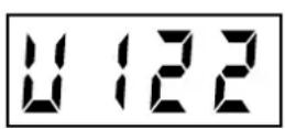
Voltage:
Displays current voltage output.
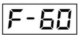
Frequency (Hz):
Displays power output frequency in Hertz.
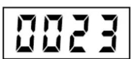
Lifetime Hours:
Displays the lifetime run hours.
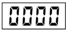
Run Time/Maintenance:
Displays current run time. Resets to zero when shut down. Maintenance reminder displayed when required.
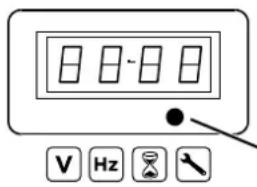
Push the Mode button to cycle through the data display modes.
Mode Button
Maintenance reminder codes will be shown on the Data Display based on unit lifetime hours. The maintenance codes will be displayed until the unit is turned off. Refer to the Maintenance section for specific procedures.
| Maintenance Code Required Maintenance | |
| P25 Change | engine oil |
| P50 Change | engine oil, clean air filter |
| P100 Change | engine oil, clean air filter, replace fuel filter |
CARTON CONTENTS
▲ CAUTION
Weight hazard. Always have assistance when lifting the generator.
- Carefully open the carton.
- Remove and save the carton contents.
- Remove and discard the packing tray.
- Unfold the top of the plastic bag enclosing the generator.
- Carefully cut the vertical corners of the carton to access the generator.
- Recycle or dispose of the packaging materials properly.
CARTON CONTENTS
- User manual
- Quick Start Guide/Maintenance Schedule
• LPG/propane hose with regulator - Remote start key fob
• Bottle of SAE 10W-30 Oil - Battery charger
- Spark plug socket wrench
- Oil Funnel
- Assembly wrench
• Wheel and lifting hook components
Item Quantity
- Lifting hook 1
- Flange bolt, M8 4
- Wheel 2
- Axle pin 2
- Washer 4
- Cotter pin 4
If any parts are missing, contact our service team at service@wpowereq.com or call 1-855-944-3571.
INSTALL WHEELS AND LIFTING BRACKET
NOTICE
Assembling the generator will require lifting the unit on one side. Install the wheels before adding fuel or oil.
▲ CAUTION
Lifting hazard. Use two people when installing the wheels. Refer to LIFTING HOOK in the OPERATION section.
- Place generator on a flat surface.
- Align the lifting hook bracket with the mounting brackets on the top of the fuel tank. Secure with four M8 flange bolts.
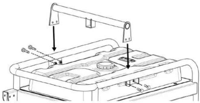
natural_image
Technical line drawing of a mechanical assembly with mounting bracket and internal components (no text or symbols)- Use the Lifting Hook to raise the unit enough to install the wheels as shown.
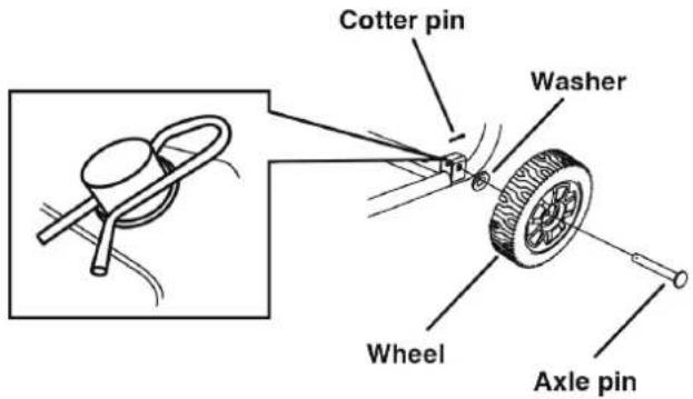
Note: The wheels are only intended for hand transport. The wheels are not suitable for towing the generator either on or off-road.
INITIAL OIL FILL
NOTICE
THIS GENERATOR HAS BEEN SHIPPED WITHOUT OIL. Do not attempt to crank or start engine before it has been properly serviced with recommended oil. Failure to add engine oil before starting will result in serious engine damage.
NOTICE
Use of 2-stroke/cycle oil or other unapproved oil types can cause severe engine damage that is not covered under warranty.
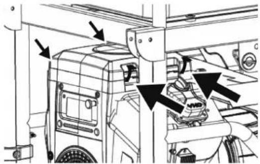
The included, recommended oil type for typical use is 10W-30 engine oil. If running the generator in extreme temperatures, refer to the following chart.
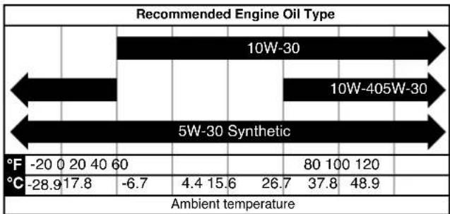
bar
Recommended Engine Oil Type | Category | Ambient temperature | |---|---| | 10W-30 | -20 0 20 40 60 | | 10W-405W-30 | -28.9 17.8 -6.7 | | Synthetic | 80 100 120 | | Ambient temperature | 4.4 15.6 26.7 37.8 48.9 |- On a level surface, remove the oil fill cap.
natural_image
Technical diagram of a mechanical assembly with no visible text or symbols-
Using the supplied funnel and oil, add the oil into the engine.
-
Replace the oil fill cap and tighten securely.
BATTERY INSTALLATION
CAUTION
Battery posts, terminals contain lead and lead compounds. Wash hands after handling.
The battery shipped with the generator has been fully charged. A battery may lose some charge when not in use for prolonged periods of time. See the BATTERY MAINTENANCE section for battery charging procedure.
Note: Once started, the generator will charge the battery after 30–60 minutes of use.
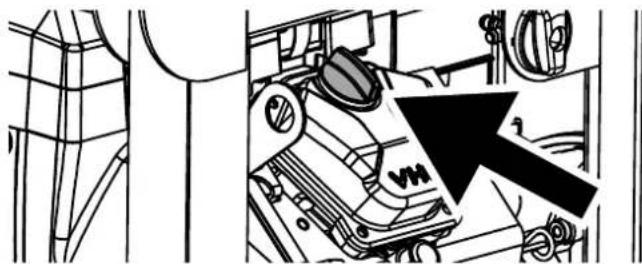
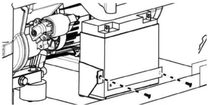
- Remove the two battery plate bolts and battery plate. Tilt the battery forward and remove.
natural_image
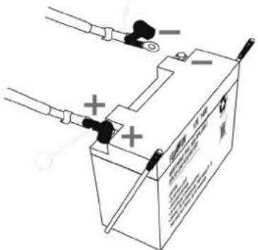
Technical line drawing of a mechanical assembly with gears and housing (no text or symbols)- Connect the positive (+) battery cable (red boot) to the positive (+) battery post. Secure the boot over the battery post.
-
Connect the negative (-) cable (black boot) to the negative (-) battery post. Secure the boot over the battery post.
-
Install the battery in the battery tray. Install the battery plate and bolts. Tighten the bolts securely.
FUEL
▲ WARNING
Fire and explosion hazard. Never use a gasoline container, gasoline tank, propane connector hose, propane tanks, or any other fuel item that is broken, cut, torn or damaged.
▲ DANGER
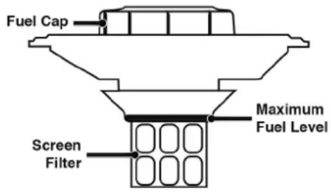
Fire and explosion hazard. Do not overfill fuel tank. Fill only to the red fill ring located in the in-tank fuel screen filter. Overfilling may cause fuel to spill onto engine causing a fire or explosion hazard.
▲ DANGER
Fire and explosion hazard. Never refuel the generator while the engine is running. Always turn the engine off and allow the generator to cool for two minutes before refueling.
NOTICE

Do not use E15 or E85 fuel in this product. Engine or equipment damage caused by stale fuel or the use of unapproved fuels (such as E15 or E85 ethanol blends) is not covered by warranty. Only use unleaded gasoline containing up to 10% ethanol.
FUEL REQUIREMENTS
- CLEAN, FRESH, unleaded gasoline, 87–93 octane.
- Up to 10% ethanol (gasohol) is acceptable (where available; non-ethanol fuel is recommended).
• DO NOT use E85 or E15.
• DO NOT use a gas oil mix. - DO NOT modify the engine to run on alternate fuels.
• DO NOT fuel indoors. - DO NOT create a spark or flame while fueling.
USING FUEL STABILIZER
Adding a fuel stabilizer (not included) extends the usable life of fuel and helps prevent deposits from forming that can clog the fuel system. Follow the manufacturer's instructions for use.
Always mix the correct amount of fuel stabilizer to gasoline in an approved gasoline container before fueling the generator. Run the generator for five minutes to allow the stabilizer to treat the entire fuel system.
FILLING THE FUEL TANK
- Turn the generator OFF and allow to cool for a minimum of two minutes before fueling.
- Place the generator on level ground in a well ventilated area.
- Clean area around fuel cap and remove the cap slowly.
NOTICE
Only fill the tank from an approved gasoline container. Make sure the gasoline container is internally clean and in good condition to prevent fuel system contamination.
- Slowly add the recommended fuel. Do not overfill. Fill only to the red maximum fill ring on the fuel screen filter visible in the filler neck.
- Install the fuel cap.
NOTICE
Fuel can damage paint and plastic. Use caution when filling the fuel tank. Damage caused by spilled fuel is not covered under warranty.
NOTICE
Clean the fuel screen filter of debris before and after each fueling. Remove the fuel screen filter by slightly compressing it while removing it from the fuel tank.
CONNECT AN LPG/PROPANE TANK
NOTICE
- The LPG/propane tank can be of any capacity but the tank must conform to the standard as listed in Fuel Safety section.
- Propane tanks that use liquid withdrawal system can not be used on these models.
- Verify the re-qualification date on the tank has not expired.
- Do not use included LPG/propane hose for any other appliances.
NOTICE
- All new tanks must be purged of air and moisture prior to filling. Used tanks that have not been plugged or kept closed must also be purged. The purging process should be done by a propane supplier (Tanks from an exchange supplier should have been purged and filled properly).
- Always position the tank so the connection between the valve and the gas inlet will not cause sharp bends or kinks in the hose.
WARNING
Explosion hazard. Do not start generator if you smell LPG. Always fully close the propane tank valve and disconnect the LPG/propane hose from the generator when not in use.
- Turn the generator OFF and place on a flat surface in a well ventilated area.
ASSEMBLY
- Verify that the propane tank valve is in the fully closed position.
- Remove the cover on the generator propane inlet valve.
- Use your fingers to hand thread the LPG/propane hose (included) to the propane inlet on the generator.
IMPORTANT: DO NOT use thread seal tape or any other type of sealant to seal the LPG/propane hose connection.
- Tighten the LPG/propane hose connector to the generator with a 19 mm or adjustable wrench. DO NOT over-tighten.
Torque: 5-10 lb-ft.
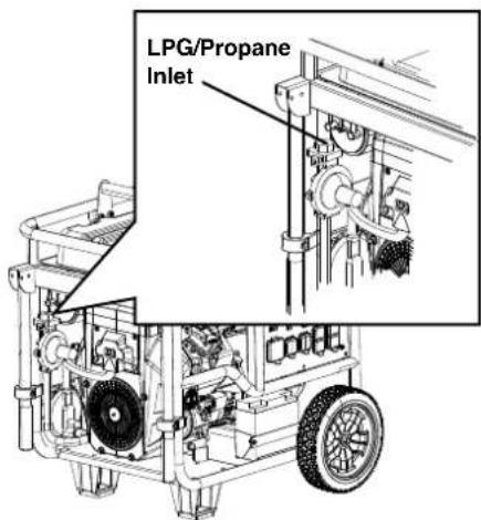
- Remove the safety plug or cap from the propane tank valve and attach the other end of the hose to the LPG/propane connector on the tank. Hand tighten.
- Turn the propane tank valve to the fully open position. Check all connections for leaks by wetting the fittings with a solution of soap and water. Bubbles which appear or bubbles which grow indicate that a leak exists. If a leak exists at a fitting, turn the propane tank valve to the fully closed position and tighten the fitting. Open the propane tank valve and recheck the fitting with the soap and water solution. If the leak continues or if the leak is not at a fitting then do not use the generator and contact customer service.
IMPORTANT: Keep the propane tank valve in the fully closed position unless in use.
GENERATOR LOCATION
Read and understand all safety information before starting the generator.
⚠️ DANGER
Using a generator indoors CAN KILL YOU IN MINUTES. Generator exhaust contains carbon monoxide. This is a poison you cannot see or smell.
NEVER use inside a home or garage, EVEN IF doors and windows are open.
Only use OUTSIDE and far away from windows, doors, and vents.
NEVER operate the generator inside any building, including garages, basements, crawlspaces, sheds, enclosure, or compartment, including the generator compartment of a recreational vehicle.
▲ DANGER
Electrocution hazard. Never use the generator in a location that is wet or damp. Never expose the generator to rain, snow, water spray, or standing water while in use. Protect the generator from all hazardous weather conditions. Moisture or ice can cause a short circuit or other malfunction in the electrical circuit. Using a generator or electrical appliance in wet conditions, such as rain or snow, or near a pool or sprinkler system, or when your hands are wet, could result in electrocution
▲ WARNING
Fire hazard. Only operate the generator on a solid, level surface. Operating the generator on a surface with loose material such as sand or grass clippings can cause debris to be ingested by the generator that could block cooling vents or the air intake system. Allow the generator to cool for 30 minutes before transport or storage.
The generator should be on a flat, level surface at all times (Even while not in operation). The generator must have at least 5 ft. (1.5 m) of clearance from all combustible material.
Do not operate the generator in the back of a SUV, camper, trailer, truck bed (regular, flat, or otherwise), under stairs, next to walls or buildings, or in any other location that will not allow for adequate cooling of the generator and/or the muffler. DO NOT contain generators during operation.
▲ DANGER
Asphyxiation hazard. Place the generator in a well-ventilated area. DO NOT place the generator near vents or intakes where exhaust fumes could be drawn into occupied or confined spaces. Carefully consider wind and air currents when positioning the generator.
GROUNDING
▲ WARNING
Shock hazard. Failure to properly ground the generator can result in electric shock.
NOTICE
Only use grounded 3-prong extension cords, tools, and appliances, or double-insulated tools and appliances.
The generator neutral is bonded to the frame. There is a permanent conductor between the generator (stator wire) and the frame. If this generator will be used only with cord and plug equipment connected to the receptacles mounted on the generator, National Electric Code does not require that the unit be grounded. However, other methods of using the generator may require grounding to reduce the risk of shock or electrocution.
Before using the ground terminal, consult a qualified electrician, electrical inspector, or local agency having jurisdiction for local codes or ordinances that apply to the intended use of the generator.
DISCONNECTING THE BONDED NEUTRAL
Removing the bonded neutral disables the GFCI protection from the 5-20R receptacles. The bonded neutral should only be removed under specific circumstances. Consult a qualified electrician to determine if your situation requires disconnecting the bonded neutral.
- Remove the alternator cover.
- Remove the bonded jumper wire and reinstall the nut.
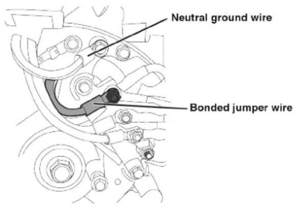
- Remove the nut securing the neutral ground wire and attach the bonded jumper wire. Reinstall the nut.
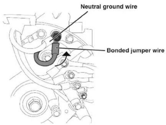
- Reinstall the alternator cover.
IMPORTANT: Apply a new "NEUTRAL UNBONDED" Label over the "NEUTRAL BONDED TO FRAME" label on the front of the control panel.
Engine power is reduced the higher you operate above sea level. Output will be reduced approximately 3.5% for every 1,000 feet of increased altitude from sea level.
High altitude adjustment is required for operation at altitudes over 2,000 ft. (762 m). Operation without this adjustment will cause decreased performance, increased fuel consumption, and increased emissions.
NOTICE
Do not operate the generator at altitudes below 2,000 ft. (762 m) with the high altitude kit installed. Engine damage may occur.
High Altitude Carburetor Kit Part# 518904
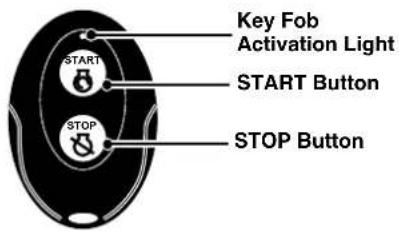
REMOTE START
WARNING
Verify that the area around the generator is clear before remote starting the generator.
The remote start key fob included with the generator should be attached to the recoil handle or control panel. If your unit was shipped without a key fob, contact Westinghouse customer service.
The generator can be started remotely from up to 99 feet (30 meter) using the remote start key fob.
Note: As the batteries in the remote start key fob drain, operational distance will decrease.
PAIRING THE REMOTE START
Remote replacement batteries: (2) CR2016
If the remote start key fob is replaced or needs re-paired to the generator, follow this procedure.
- Turn the generator battery switch to the ON position. The power indicator light will illuminate.
- Push and hold the red Pairing button on the back of the control panel until the START/STOP button illuminates.
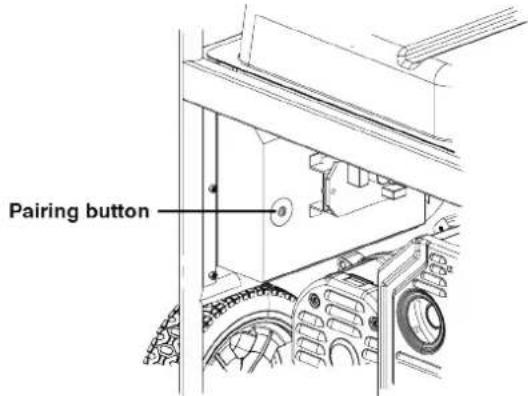
- Push and hold the STOP button on the key fob until the START/STOP button illumination turns OFF. Release the button. The START/STOP button will illuminate after the button is released.
-
Push and hold the START button on the key fob until the START/STOP button illumination turns OFF. Release the button. The START/STOP button will illuminate after the button is released.
-
Push the Pairing button on the side of the control panel until the START/STOP button illumination turns OFF. Release the button.
-
Turn the generator battery switch to the OFF position. The remote is now paired.
FUEL SELECTOR SWITCH
Position the fuel selector switch on the front control panel to the desired fuel choice.

GASOLINE
GASOLINA
DE L'ESSENCE


PROPANE PROPANO
Push the fuel selector switch fully upward for gasoline operation.
Push the fuel selector switch fully downward for propane operation.
BREAK-IN PERIOD
For proper break-in, do not exceed 50% of the rated running watts (6000 watts) during the first five hours operation.
Vary the load occasionally to allow stator windings to heat and cool and help seat the piston rings.
LOW IDLE
NOTICE
Always start the generator with Low Idle OFF. Allow the engine speed to stabilize before switching Low Idle ON.
NOTICE
Frequency output of the generator is dependent on engine speed. DO NOT use Low Idle when powering sensitive electronics or large surge loads, such as an air conditioner, electric pump, refrigerator, or when connected to a home transfer switch.
Low Idle minimizes fuel consumption, noise, and engine wear by lowering the engine RPM to idle (2400 RPM) when electrical loads have been turned off and automatically returns to rated speed when loads are turned back on.
Turn Low Idle ON when powering intermittent, non-electronic loads, such as power tools at a construction site.
BEFORE STARTING THE GENERATOR
Verify that:
- The generator is placed in an safe, appropriate location.
- The generator is on a dry, flat, and level surface.
• The engine is filled with oil. - All loads are disconnected.
▲ DANGER
Fire and explosion hazard. DO NOT move or tip the generator during operation.
STARTING THE ENGINE: GASOLINE
During Push-Button or Remote Start the engine will automatically set the choke and begin the start sequence. If the engine fails to start, the generator will attempt to start the engine two more times. The battery switch can be turned off at any time during the automatic start sequence to abort the engine start attempt.
If the cranking speed drops after each unsuccessful attempt, then the battery may not be adequately charged. See BATTERY MAINTENANCE section.
- Verify that fuel is in the gas tank.
- Turn the fuel selector switch to gasoline operation.
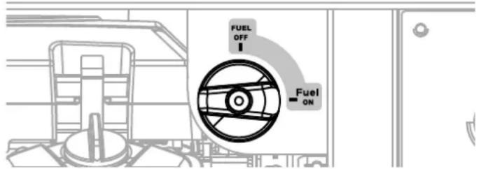
- Turn the fuel tank valve to the ON position.
- Push the battery switch to the ON position.
- Choose the starting method:
a. Remote Start: Push and hold the START button on the remote start key fob for one second.
b. Push-Button Start: Push and hold the engine START/STOP button for two seconds.
STARTING THE ENGINE: PROPANE
▲ DANGER
Fire and explosion hazard. Always turn the propane tank valve to the fully closed position if not operating the generator on propane.
- Make sure the LPG/propane hose is correctly connected to the generator and propane tank.
- Turn the fuel selector switch to propane operation.
- Fully open the valve on the propane tank.
- Push the battery switch to the ON position.
- Choose the starting method:
a. Remote Start: Push and hold the START button on the remote start key fob for one second.
b. Push-Button Start: Push and hold the engine START/STOP button for two seconds.
SWITCHING FUEL SOURCES
▲ DANGER
Fire and explosion hazard. DO NOT add gasoline to the fuel tank or connect the LPG/propane hose to the generator while the generator is in operation.
GASOLINE TO PROPANE
IMPORTANT: Load capacity is reduced when running on propane. Make sure the generator can supply enough (running) and surge (starting) watts for the items you are powering before switching to propane.
- Fully open the valve on the propane tank.
- Turn the fuel selector switch to propane operation.
- Turn the fuel tank valve to the OFF position.
PROPANE TO GASOLINE
- Turn the fuel tank valve to the ON position.
- Turn the fuel selector switch to gasoline operation.
- Turn the propane tank valve to the fully closed position.
Note: When switching to propane operation the engine may run rough for a few seconds while it purges gasoline in the carburetor.
STOPPING THE ENGINE
- Turn off and unplug all connected electrical loads.
IMPORTANT: Never start or stop the generator with electrical devices connected. - Let the generator run with no load for several minutes to stabilize internal temperatures of the engine.
- Push and hold the START/STOP button for one second or push STOP on the remote start key fob for one second.
Note: Alternately, if the generator is used infrequently, turn the fuel tank valve to the OFF position to limit the residual fuel remaining in the system. The engine will stop when fuel in the carburetor and fuel line is exhausted. - Push the battery switch to the OFF position.
- If operating on propane, turn the propane tank valve to the fully closed position.
FREQUENCY OF USE
If the generator will be used on an infrequent or intermittent basis (more than one month before next use), refer to the Battery Maintenance and Storage sections of this manual for information regarding battery charging and fuel deterioration.
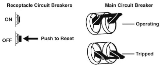
AC CIRCUIT BREAKERS
The circuit breakers will automatically switch OFF if there is a short circuit or a significant overload of the generator at each receptacle.
If an AC circuit breaker switches OFF automatically, check that the appliance is working correctly and it does not exceed the rated load capacity of the circuit before resetting the AC circuit breaker ON.
The main circuit breaker controls total output of all outlets to protect the generator from overload or short circuit.
GENERATOR CAPACITY
NOTICE
Do not overload the generator's capacity. Exceeding the generator's wattage/amperage capacity can damage the generator and/or electrical devices connected to it.
Make sure the generator can supply enough continuous (running) and surge (starting) watts for the items you will power at the same time.
The total power requirements (Volts x Amps = Watts) of all appliances connected must be considered. Appliance and power tool manufacturers usually list rating information near the model or serial number.
To determine power requirements:
- Select the items you will power at the same time.
- Total the continuous (running) watts of these items. This is the amount of power the generator must produce to keep the items running. See the wattage reference chart on the next page.
- Estimate how many surge (starting) watts you will need. Surge wattage is the short burst of power needed to start electric motor-driven tools or appliances such as a circular saw or refrigerator. Because not all motors start at the same time, total surge watts can be estimated by adding only the item(s) with the highest additional surge watts to the total rated watts from step 2.
Example:
| Tool or Appliance | Running Watts* | Starting Watts* |
| RV Air Conditioner (11,000 BTU) 1010 1600 | ||
| TV (Tube Type) 300 0 | ||
| RV Refrigerator 180 600 | ||
| Radio 200 0 | ||
| Light (75 Watts) 300 0 | ||
| Coffee Maker 600 0 | ||
| 2590 Total | 1600 | |
| Running Watts* | Highest Starting Watts* | |
| Total Running Watts 2590 | ||
| Highest Starting Watts + 1600 | ||
| Total Starting Watts Needed 4190 | ||
*Wattages listed are approximate. Verify actual wattage.
POWER MANAGEMENT
To prolong the life of the generator and attached devices, use care when adding electrical loads to the generator. There should be nothing connected to the generator outlets before starting the engine. The correct and safe way to manage generator power is to sequentially add loads as follows:
- With nothing connected to the generator, start the engine as described in this manual.
- Plug in and turn on the first load, preferably the largest load you have.
- Permit the generator output to stabilize (engine runs smoothly and attached device operates properly).
- Plug in and turn on the next load.
- Again, permit the generator to stabilize.
- Repeat steps 4 and 5 for each additional load.
Wattage Reference
| Tool or Appliance | Estimated Running Watts* | Estimated Starting Watts* |
| Incandescent Lights(4 Quantity x 75 Watts) | 300 0 | |
| TV (Tube Type) 300 0 | ||
| Sump Pump (1/3 hp) 800 1300 | ||
| Refrigerator or Freezer | 700 2200 | |
| Well Pump (1/3 hp) | 1000 | 2000 |
| Furnace (1/2 hp) | 800 2350 | |
| Radio | 200 0 | |
| Drill (3/8", 4 amps) | 440 | 600 |
| Circular Saw(Heavy Duty, 7-1/4") | 1400 | 2300 |
| Miter Saw (10") | 1800 | 1800 |
| Table Saw (10") | 2000 | 2000 |
*Wattages listed are approximate. Verify actual wattage.
EXTENSION CORDS
▲ WARNING
Asphyxiation hazard. Extension cords running directly into the home increase the risk of carbon monoxide poisoning through any openings. If an extension cord running directly into your home is used to power indoor items, there is a risk of carbon monoxide poisoning to people inside the home. Always use battery-powered carbon monoxide detector (s) that meet current UL 2034 safety standards when running the generator. Regularly check the detector (s) battery.
▲ WARNING
Asphyxiation hazard. When operating the generator with extension cords, make sure the generator is located in an open, outdoor area, far away from occupied spaces with exhaust pointed away.
▲ WARNING
Fire and electrocution hazard. Never use worn or damaged extension cords. Damaged or overloaded extension cords could overheat, arc, and burn resulting in death or serious injury.
Before connecting an AC appliance or power cord to the generator:
- Use grounded 3-prong extension cords, tools, and appliances, or double-insulated tools and appliances.
- Make sure the tool or appliance is in good working order. Faulty appliances or power cords can create a potential for electric shock.
- Make sure the electrical rating of the tool or appliance does not exceed the rated power of the generator or the receptacle being used.
EXTENSION CORD SIZING
Only use grounded 3-prong extension cords marked for outdoor use that are rated for the electrical load.
| Total Amperage | Minimum Gauge, Outdoor Rated | |
| Up to 50 FT (15 M) | Up to 100 FT (30 M) | |
| Up to 10A |  |  |
| Up to 15A |  |  |
| Up to 20A |  |  |
| Up to 30A |  |  |
| Up to 35A |  |  |
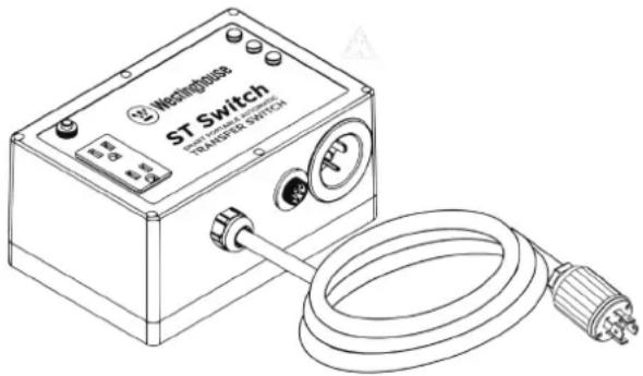
ST SWITCH
The generator is compatible with the Westinghouse ST Switch, purchased separately. When utility power is on it will provide power (up to 120V @ 20A) to the appliances plugged into the 5-20R receptacle on the ST Switch. When utility power is lost the ST Switch automatically transfers input power from utility to generator power. When utility power is restored, the ST Switch transfers input power back to utility. Visit www.westinghouseoutdoorpower.com for more information.
TRANSPORTING
▲ CAUTION
Weight hazard. Always have assistance when lifting the generator.
- Allow the generator to cool a minimum of 30 minutes before transporting.
- If operating on propane, turn the propane tank valve to the fully closed position.
- Disconnect the LPG/propane hose from the generator and propane tank.
- Replace all protective covers on the generator control panel.
- Keep the unit level during transport to minimize the possibility of fuel leakage or, if possible, drain the fuel or run the engine until the fuel tank is empty before transport.
- The generator wheels are only intended for hand transport. The wheels are not suitable for towing the generator either on or off-road.
- Use the extendable handle for hand transport. Only use the handle while the generator is OFF, stationary, and resting on a horizontal surface. Do not use the handle to lift the generator entirely off the ground, tow it, or up-end it.
▲ CAUTION
Fire hazard. Do not up-end the generator or place it on its side. Fuel or oil can leak and damage to the generator may occur.
LIFTING HOOK
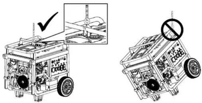
Only use the lifting hook to lift the unit or attach any load restraints such as ropes or tie-down straps. Do not attempt to lift or secure the generator by holding onto any of its other components.
Before lifting the generator, inspect the bracket and make sure it is securely fastened to the generator. Do not lift the generator unless the lifting bracket is securely fastened.
- Hook a chain or strap through the eye on the lifting hook and make sure it is securely fastened.
- Connect a suitable lifting device to the chain or strap. Inspect chain and hook for any damaged links or any defects that could cause failure. It is recommended to use hooks with safety latches installed.
- Lift the generator slightly to ensure it is lifting straight and level.
▲ WARNING
Accidental start-up. Disconnect the spark plug boot from the spark plugs when performing maintenance on the generator.
MAINTENANCE SCHEDULE
Regular maintenance will improve performance and extend the service life of the generator. Follow the hourly or calendar intervals, whichever occurs first. More frequent service is required when operating in adverse conditions as noted below.
Before Each Use
Check engine oil Check air filter
After First 20 Hours or First Month
Change engine oil ^1
After 50 Hours or Every 3 Months
Clean air filter ^2
After 100 Hours or Every 6 Months
Change engine oil ^1 Inspect/clean spark arrestor Inspect/clean spark plug Replace fuel filter Clean float bowl ^8
After 300 Hours or Every Year
Replace spark plug Replace air filter Replace fine oil filter Inspect/adjust valve clearance ^3
Every 2 years
Replace fuel pipe
1 Change oil every month when operating under heavy load or in high temperatures.
^2 Clean more often under dirty or dusty conditions. Replace air filter if it cannot be adequately cleaned.
^3 Recommend service to be performed by authorized Westinghouse service dealer.
MAINTENANCE REPLACEMENT PARTS
| Description Part Number | |
| Air filter 5061 | |
| Oil drain bolt crush washer 942 | 42 |
| Battery, 21 AH 511015 | |
| Fuel filter 516401 | |
| Spark plug 97110 (5357) | |
AIR FILTER MAINTENANCE
The air filter must be cleaned after every 50 hours of use or six months (frequency should be increased if the generator is operated in a dusty environment).
- Place the generator on a level surface and allow the engine to cool for several minutes.
- Release the four clips then remove the air filter cover.
- Remove the air filter and clean using compressed air. DO NOT submerge the filter in liquids or add oil.
- Install the air filter in the housing, making sure it is correctly oriented and seated in the housing.
TopBottom

natural_image
Two 3D block diagrams showing different surface patterns: one with a black top and one with a grid-patterned bottom (no text or symbols)- Install the air cleaner cover and secure with the cover clips.
ENGINE OIL LEVEL CHECK
CAUTION
Avoid skin contact with engine oil. Wear protective clothing and equipment. Wash all exposed skin with soap and water.
NOTICE
Always use the specified engine oil. Failure to use the specified engine oil can cause accelerated wear and/or shorten the life of the engine.
When using the generator in dusty conditions or in extremely hot weather, change the oil more frequently.
Ambient air temperature will affect engine oil performance. Change the type of engine oil used based on weather conditions.
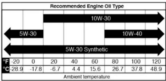
heatmap
Recommended Engine Oil Type | Category | 5W-30 (°F) | 5W-30 (°C) | 10W-30 (°F) | 10W-30 (°C) | 5W-30 Synthetic (°F) | 5W-30 Synthetic (°C) | |---|---|---|---|---|---|---| | Ambient temperature | -20 | -28.9 | 0 | -17.8 | 20 | -6.7 | | Ambient temperature | 40 | 4.4 | 60 | 15.6 | 80 | 26.7 | | Ambient temperature | 80 | 26.7 | 100 | 37.8 | 120 | 48.9 | The chart displays a single bar representing the combined value of 5W-30 and 10W-30 for Ambient temperature. The 'Recommended Engine Oil Type' column is not explicitly labeled in the image but corresponds to the color scale on the right.Check the engine oil level before each use or every 8 hours of operation.
- Place the generator on a level surface and allow the engine to cool for several minutes.
- Remove the oil dipstick and wipe the dipstick clean.
- Insert, then remove the oil dipstick.
Acceptable Oil Level – On the flat side of the dipstick, oil is visible up to the first notch.
Low Oil – Oil is below the first notch on the dipstick
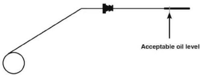
- If low, remove the oil fill cap and add the recommended engine oil incrementally and recheck until the level is at the top notch on the dipstick. DO NOT overfill. If over the top notch on the dipstick, drain the oil to reduce the oil level to the full mark.
- Replace the oil dipstick and oil fill cap.
ENGINE OIL CHANGE
When using the generator in dusty conditions or extremely hot weather, change the oil more frequently. Change the oil while the engine is still warm from operation.
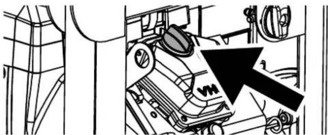
- Place the generator on a level surface and allow the engine to cool for several minutes.
- With a damp rag, clean around the oil fill cap. Remove the oil fill cap.
- Place an oil pan (or suitable container) under the oil drain hose.
- Unclip the oil drain hose and twist the cap counterclockwise to allow the oil the to drain.
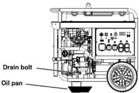
- Twist the cap clockwise to close. Secure the hose in the hose clip.
- Place the oil pan under the oil filter. Remove the oil filter by rotating it counterclockwise. Allow the oil to drain completely. Clean the area where the oil filter contacts the engine.
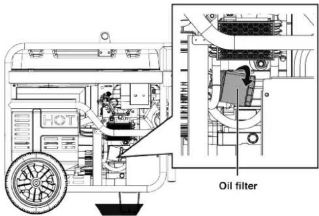
- Apply clean oil to the rubber seal on the new oil filter. Install by hand, turning clockwise until the seal contacts the engine then turn another 3/4 turn. DO NOT over tighten.
- Fill with the recommended oil. Stop frequently to check the oil level. Do not overfill. If the engine is overfilled, the excess oil may get transferred to the air cleaner housing and air filter. An indication of overfilling is white or blue smoke coming from the muffler when the engine is running.
natural_image
Technical diagram of a mechanical assembly with no visible text or symbolsMaximum oil capacity: 1.7 Quart (1.6 Liter)
- Install the oil dipstick. Screw in the oil fill cap securely.
NOTICE
Do not pollute. Follow the guidelines of the EPA or other governmental agencies for proper disposal of hazardous materials. Consult local authorities or reclamation facility.
SPARK PLUG MAINTENANCE
NOTICE
Always use the Westinghouse OEM or compatible non-resistor-type spark plug. Use of resistor-type spark plug can result in rough idling, misfire, or may prevent the engine from starting.
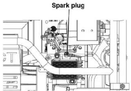
Inspect and clean the spark plugs after every 100 hours of use or six months. Replace the spark plugs after 300 hours of use or every year.
-
Place the generator on a level surface and allow the engine to cool.
-
Remove the spark plug boots by firmly pulling the boot directly away from the engine.
-
Clean the area around the spark plugs.
-
Remove the spark plugs with the included spark plug socket wrench.
NOTICE
Never apply any side load or move the spark plug laterally when removing the spark plug.
-
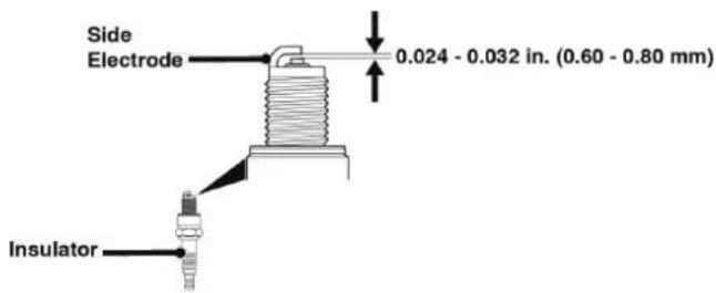
Inspect the spark plugs. Replace if electrodes are pitted, burned, or the insulator is cracked. Only use a recommended replacement plug.
-
Measure the spark plug electrode gap with a wire-type feeler gauge. If necessary, correct the gap by carefully bending the side electrode.
Spark plug gap: 0.024 - 0.032 in. (0.60 - 0.80 mm)
-
Carefully install each spark plug finger tight, then tighten as additional 3/8 to 1/2 turn with the spark plug wrench.
-
Attach the spark plug boots.
SPARK ARRESTOR SERVICE
Allow the muffler to cool completely before servicing the spark arrestor. Check and clean the spark arrestor after every 100 hours of use or six months. Failure to clean the spark arrestor will result in degraded engine performance.
-
Place the generator on a level surface.
-
Carefully remove the carbon deposits from the spark arrestor screen with a wire brush. The spark arrestor must be free of breaks and tears. Use compressed air to clear removed deposits.
natural_image
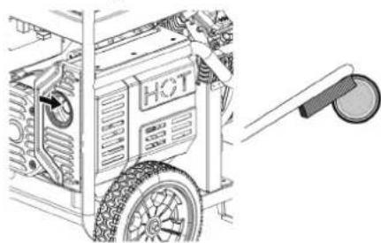
Technical line drawing of a hot water heater with visible fan and control panel (no text or symbols)FUEL FILTER
Replace the fuel filter after 100 hours of use.
Note: Have an appropriate gasoline container and rags ready to catch residual fuel in the filter and fuel line.
-
Allow the generator to cool completely.
-
Turn the fuel valve to the OFF position.

-
Note the orientation of the fuel filter. Using pliers, remove the fuel line clamps and remove the fuel filter.
-
Install the new fuel filter in the reverse order of removal.
BATTERY MAINTENANCE
WARNING
The battery gives off explosive hydrogen gas during normal operation. A spark or flame can cause the battery to explode with enough force to kill or seriously hurt you. Wear protective clothing and a face shield, or have a skilled technician perform battery maintenance.
WARNING
Burn hazard. The battery contains sulfuric acid (electrolyte) which is highly corrosive and poisonous. Wear protective clothing and eye protection when working near the battery. Keep children away from the battery.
WARNING
NEVER smoke or work near sparks or other sources of ignition. NEVER touch both battery terminals at the same time with your hand or any non-insulated tools. If battery acid contacts skin or clothing, flush immediately with water and neutralize with baking soda.
The battery shipped with the generator has been fully charged. A battery may lose some charge when not in use for prolonged periods of time.
Note: Once started, the generator will charge the battery after 30–60 minutes of use.
When the generator is not running, the included trickle charger can remain connected and will maintain the battery for an indefinite period of time. A red light on the charger indicates charging in progress. A green light indicates charging complete. Charge in a dry location.
- Plug the charger into the battery charging port on the control panel.
- Plug the wall receptacle end of the battery charger into a 120 Volt AC wall outlet.
BATTERY REPLACEMENT
CAUTION
Battery posts, terminals contain lead and lead compounds. Wash hands after handling.
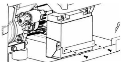
- Remove the two battery plate bolts and battery plate. Tilt the battery forward and remove.
natural_image
Technical line drawing of a mechanical assembly with gears and housing (no text or symbols)- Disconnect the negative (−) cable (black boot) from the negative (−) battery post.
- Disconnect the positive (+) battery cable (red boot) from the positive (+) battery post.
NOTICE
Always connect the cables in the following sequence to avoid possible shock.
- On the replacement battery, connect the positive (+) battery cable (red boot) to the battery positive (+) terminal. Secure the boot over the battery post.
- Connect the negative (−) battery cable (black boot) to the negative (−) positive terminal. Secure the boot over the battery post.
- Install the battery in the battery tray. Install the battery plate and bolts. Tighten the bolts securely.
NOTICE
Dispose of the used battery properly according to the guidelines established by your local or state government.
STORAGE
Proper storage preparation is required for trouble-free operation and generator longevity.
NOTICE
Gasoline stored for as little as 30 days can deteriorate, causing gum, varnish, and corrosive buildup in fuel lines, fuel passages, and the engine. This corrosive buildup restricts the flow of fuel, which can prevent the engine from starting after a prolonged storage period. The use of fuel stabilizer significantly increases the storage life of gasoline. Full-time use of fuel stabilizer is recommended. Follow the manufacturer's instructions for use.
STORAGE TIME RECOMMENDED PROCEDURE
| Less than 1 month No | service required. |
| 2 to 6 months | Fill with fresh gasoline and add gasoline stabilizer. Drain the carburetor float bowl. |
| 6 months or longer | Drain the fuel tank and carburetor float bowl. |
SHORT TERM STORAGE
- Allow the generator to cool a minimum of 30 minutes before storage.
- If operating on propane, turn the propane tank valve to the fully closed position and disconnect the LPG/propane hose from the generator and propane tank.
- Replace all protective covers on the generator control panel.
- Wipe the generator with a moist cloth. Clean any debris from the muffler cooling vents.
- Store the generator in a well-ventilated, dry location away from sparks, open flames, pilot lights, heat, and other sources of ignition such as areas with a spark-producing electric motor or where power tools are operated.
- Do not store the generator, gasoline, or propane tanks near furnaces, water heaters, or any other appliances that produce heat or have automatic ignitions.
- With the engine and exhaust system cool and all surfaces dry, cover the generator to keep out dust. Do not use a plastic sheet as a dust cover. Non-porous materials trap moisture and promote rust and corrosion.
LONG TERM STORAGE
Even properly stabilized fuel can leave residue and cause corrosion if left long term. If storing the generator for over six months, drain the fuel tank.
DRAINING THE FUEL TANK
If storing the generator for longer than six months, drain the fuel tank to prevent fuel separation, deterioration, and deposits in the fuel system.
- Unscrew the fuel tank cap. Remove the fuel screen filter by slightly compressing it while removing it from the tank.
-
Using a commercially available gasoline hand pump (not included), siphon the gasoline from the fuel tank into an approved gasoline container. DO NOT use an electric pump.
OR
Disconnect the fuel line from the bottom of the fuel tank and allow the fuel to drain into an approved gasoline container. Reinstall the fuel line. -
Reinstall the fuel screen filter and the fuel tank cap.
-
Start the generator and allow it to run until the generator engine stops.
-
Push the battery switch to the OFF position.
-
Disconnect the battery.
VALVE CLEARANCE
NOTICE
Checking and adjusting valve clearance must be done when the engine is cold.
Perform this procedure on both cylinders.
- Remove the rocker arm cover and carefully remove the gasket. If the gasket is torn or damaged, it must be replaced.
- Remove the spark plug so the engine can be rotated more easily.
- Rotate the engine to Top Dead Center (TDC) by momentarily pushing the Start button. Looking through the spark plug hole, the piston should be at the top (both valves are closed).
- Both the rocker arms should be loose at TDC on the compression stroke. If they are not, rotate the engine 360°.
- Insert a feeler gauge between the rocker arm and the valve stem to measure valve clearance.
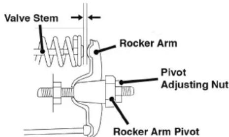
Intake Valve Exhaust Valve
| Valve Clearance | 0.0031 – 0.0047 in(0.08 – 0.12 mm) | 0.0051 – 0.0067 in(0.13 – 0.17 mm) |
| Torque 8-12 N·m 8-12 N·m | ||
- If an adjustment is necessary, hold the rocker arm pivot and loosen the pivot adjusting nut.
- Turn the rocker arm pivot to obtain the specified clearance. Hold the rocker arm pivot and re-tighten the pivot adjusting nut to the specified torque.
Torque: 106 inch-pound (12 N·m)
- Perform this procedure for the other valve.
- Install the gasket, rocker arm cover, and spark plug.
| PROBLEM POSSIBLE CAUSE CORRECTION | ||
| Engine will not start | Battery switch in the OFF position. Turn battery switch to the ON position. | |
| Out of fuel. Refuel. | ||
| Bad fuel, generator stored without treating or draining gasoline, or refueled with bad gasoline. | Drain the fuel tank. Refuel with fresh gasoline. | |
| Dirty air filter. Clean the air filter. | ||
| Low engine oil level stopped generator. If low oil LED illuminated, turn battery switch to the OFF position. Add engine oil. | ||
| Spark plug wet with fuel (flooded engine). | Wait five minutes. Turn battery switch to the OFF position. Pull recoil handle rapidly several times. If the generator does not start, remove spark plug and dry. | |
| Spark plug faulty, fouled, or improperly gapped. | Gap or replace the spark plug. Reinstall. | |
| Fuel filter restricted, fuel system malfunction, fuel pump failure, ignition malfunction, valves stuck, etc. | Contact Westinghouse customer service toll-free at 1 (855) 944-3571. | |
| Battery drained. Use the recoil handle to start the generator. | ||
| Choke partially open or closed due to weak or disconnected battery. | Manually set the choke. See Maintenance section. | |
| CO sensor removed or modified. Return to original configuration. | ||
| CO sensor activated or system fault occurred. | Relocate generator / Contact Westinghouse customer service toll-free at 1 (855) 944-3571. | |
| Engine starts, then shuts down | Out of fuel. Refuel. | |
| Incorrect engine oil level. Check engine oil level. | ||
| Dirty air filter. Clean the air filter. | ||
| Contaminated fuel. Drain the fuel tank. Refuel with fresh gasoline. | ||
| Defective low oil level switch. Contact Westinghouse customer service toll-free at 1 (855) 944-3571. | ||
| Engine lacks power | Air filter restricted. Clean or replace air filter. | |
| Bad fuel, generator stored without treating or draining gasoline, or refueled with bad gasoline. | Drain the fuel tank. Refuel with fresh gasoline. | |
| Fuel filter restricted, fuel system malfunction, fuel pump failure, ignition malfunction, valves stuck, etc. | Contact Westinghouse customer service toll-free at 1 (855) 944-3571. | |
| Engine runs rough or bogs when load applied | Dirty air filter. Clean the air filter. | |
| Generator overloaded. Unplug some devices. | ||
| Faulty power tool or appliance. Replace or repair tool or appliance. Stop and restart the engine. | ||
| Fuel filter restricted, fuel system malfunction, fuel pump failure, ignition malfunction, valves stuck, etc. | Contact Westinghouse customer service toll-free at 1 (855) 944-3571. | |
| No power at AC receptacles | OUTPUT READY LED is OFF and OVERLOAD LED is ON. | Check AC load. Stop and restart engine. |
| Check the air inlet. Stop and restart the engine. | ||
| AC circuit breaker/s tripped. Check AC loads and reset circuit breaker/s. | ||
| Faulty power tool or appliance. Replace or repair tool or appliance. Stop and restart the engine. | ||
| Faulty generator. Contact Westinghouse customer service toll-free at 1 (855) 944-3571. | ||
| Frost on the propane tank or regulator | If the temperature of the propane tank drops below the dew point, condensation on the tank may turn to frost or ice. This typically occurs in humid conditions. | Providing all the propane fuel handling equipment is functioning normally, no correction is needed. |
| The Propane tank is not equipped with an Overfilling Prevention Device (OPD). | If you suspect your propane fuel tank is not equipped with an OPD device, discontinue operation immediately and replace the propane fuel tank with a propane tank equipped with a an OPD. | |
| Propane fuel tank overfilled. If you suspect your propane fuel tank has been overfilled, discontinue operation immediately and return the propane fuel tank to the place of purchase or refilling. | ||
| Propane fuel smell | Fuel regulator or fuel hose and fittings not securely sealed. | Using a soap solution check each connection and tighten as needed. |
| Propane fuel regulator vent active. The propane fuel regulator is equipped with a vent that will allow a small amount of propane fuel vapor to escape from the regulator when the propane tank valve is opened. This can be normal providing the venting of the propane is brief. If you suspect that this is abnormal, immediately discontinue use and have the propane regulator inspected by a qualified technician. | ||
| Residual fuel from the carburetor dispersing after operation. | Normal, no correction is needed. | |
| Poor performance or engine stalling on Propane | Propane fuel line kinked or crushed. Inspect propane fuel line and remove kinks or other obstructions. | |
| Fuel selector valve not properly positioned. | Rotate the fuel valve fully until the pointer is directly in line with the desired fuel. | |
| Gasoline not purged from the carburetor before switching to propane. | Close the propane fuel tank valve. Move the fuel selector switch to gas. Start the engine and allow the engine to run until the gasoline has been consumed in the carburetor. Begin propane start up procedure. | |
WGen12000DFc
Generador Portátil de Combustible Dual
Gasolina: 12,000 Vatios en Funcionamiento | 15,000 Vatios de arranque
Propano: 10,800 Vatios en Funcionamiento | 13,500 Vatios de arranque
MANUAL DE USUARIO
NO DEVUELVA ESTE PRODUCTO A LA TIENDA
Westinghouse Outdoor Power
Warranty registration
777 Manor Park Drive
Columbus, OH 43228
Para su archivo
https://westinghouseoutdoorpower.com/pages/manuals


natural_image
Technical line drawing of a mechanical assembly with no visible text or symbolsnatural_image
Technical line drawing of a mechanical assembly with no visible text or symbolsnatural_image
Technical line drawing of a mechanical assembly with gears and housing (no text or symbols)natural_image
Technical line drawing of a mechanical assembly with no visible text or symbolsnatural_image
Technical line drawing of a portable gas stove with wheels and a labeled component (no text or symbols present)natural_image
Technical line drawing of a mechanical assembly with gears and housing (no text or symbols)NE PAS RETOURNER CE PRODUIT AU MAGASIN
CENTRE DE DONNÉES....13
RAPPELS D'ENTRETIEN....13
ASSEMBLÉ
INSTALLER LES ROUES ET LE SUPPORT DE LEVAGE .... 14
REMLISSAGE D'HUILE INITIAL....14
INSTALLATION DE LA BATTERIE....15
CARBURANT....15
REMLIR LE RÉSERVOIR DE CARBURANT ....16
CONNEXION D'UN RÉSERVOIR DE GPL/PROPANE ..... 16
OPÉRATION
EMPLACEMENT DU GÉNÉRATEUR....17
MISE À LA TERREMISE À LA TERRE....18
FONCTIONNEMENT À HAUTE ALTITUDE....18
DÉMARRAGE À DISTANCE....19
SÉLECTEUR DE CARBURANT ....19
PÉRIODE DE RODAGE 19
AVANT DE DÉMARRER LE GÉNÉRATEUR ......19
DÉMARRAGE DU MOTEUR: ESSENCE....20
DÉMARRAGE DU MOTEUR: PROPANE....20
CHANGEMENT DE SOURCE DE CARBURANT ....20
ARRÊT DU MOTEUR 21
FRÉQUENCE D'UTILISATION ....21
DISJONCTEURS AC 21
CAPACITÉ DU GÉNÉRATEUR....21
GESTION DE L'ALIMENTATION ......22
RALLONGES 22
DIMENSIONS DU CORDON D'EXTENSION....23
INTERRUPTEUR ST....23
TRANSPORT 23
ENTRETIEN
CALENDRIER DE MAINTENANCE....25
RAPPELS D'ENTRETIEN....25
PIÈCES DE RECHANGE D'ENTRETIEN....25
Westinghouse Outdoor Power
Warranty registration
777 Manor Park Drive
Columbus, OH 43228
Pour vos dossiers
Date d'achat:
- Disconnect the spark plug wire to prevent accidental starting.

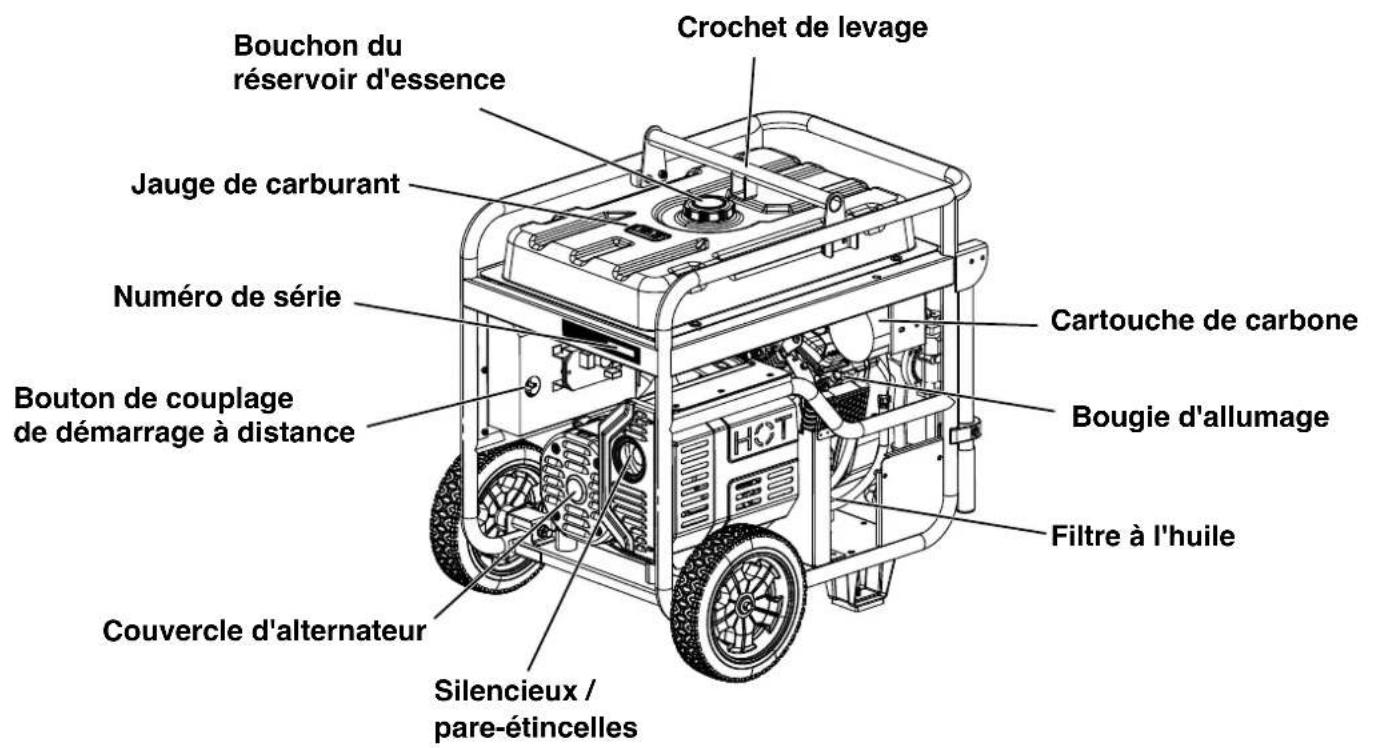
COMPOSANTS DU GÉNÉRATEUR
natural_image
Technical line drawing of a mechanical assembly with mounting bracket and internal components (no text or symbols)natural_image
Technical line drawing of a mechanical assembly with no visible text or symbolsnatural_image
Technical line drawing of a mechanical assembly with gears and housing (no text or symbols)DIMENSIONS DU CORDON D'EXTENSION
natural_image
Two 3D block diagrams showing different surface patterns: one with black top and one with grid-like structure (no text or symbols)natural_image
Technical line drawing of a mechanical assembly with no visible text or symbolsnatural_image
Technical line drawing of a portable electricity generator with visible fan and wheels (no text or symbols)FILTRE À CARBURANT
Note : Once started, the generator will charge the battery after 30–60 minutes of use.
natural_image
Technical line drawing of a mechanical assembly with gears and housing (no text or symbols)Couple: 106 inch-pound (12 N·m)
natural_image
Blue circular icon with a white crown symbol (no text or numbers)www.WestinghouseOutdoorPower.com
Service Hotline (855) 944-3571
777 Manor Park Drive, Columbus, OH 43228
and Westinghouse are trademarks of Westinghouse Electric Corporation.
Used under license by Westinghouse Outdoor Power Equipment.
© 2023 MWE Investments, LLC All Rights Reserved.