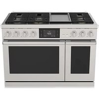
DOP48T963DS - Cooker Dacor - Free user manual and instructions
Find the device manual for free DOP48T963DS Dacor in PDF.


| Product Type | Dual Fuel Range (Gas/Electric) |
| Brand | Dacor |
| Model | DOP48T963DS |
| Dimensions (W x H x D) | 1216 x 946 x 750 mm (without grate) |
| Electrical Supply | 240 V, 60 Hz, 50 A, Single Phase |
| Gas Type | Natural Gas (convertible to LPG) |
| Surface Burners | 6 burners: left front 18,000 BTU, right front 16,000 BTU, left rear 16,000 BTU, right rear 16,000 BTU, center front 22,000 BTU, center rear 9,000 BTU (NG) |
| Oven Functions | Convection, broil, bake, roast |
| Self-Cleaning | Yes, high-temperature self-cleaning cycle |
| Cooktop Material | Stainless steel with cast-iron grates |
| Oven Door | Double-glazed, removable for cleaning |
| Controls | Rotary knobs for burners, electronic display for oven |
| Safety | Anti-tip device, control and door lock |
| Included Accessories | 3 racks, 1 metal grid, 2 temperature probes, 1 wok ring, 1 fry pan tray |
| Maintenance and Cleaning | Manual cleaning of burners, oven self-cleaning cycle, wiping stainless steel surfaces |
| Spare Parts | Available through Dacor after-sales service (LPG nozzle kit, burner caps, etc.) |
| General Information | For indoor domestic use, installation by a qualified professional recommended |
Frequently Asked Questions - DOP48T963DS Dacor
User questions about DOP48T963DS Dacor
0 question about this device. Answer the ones you know or ask your own.
Ask a new question about this device
Download the instructions for your Cooker in PDF format for free! Find your manual DOP48T963DS - Dacor and take your electronic device back in hand. On this page are published all the documents necessary for the use of your device. DOP48T963DS by Dacor.
USER MANUAL DOP48T963DS Dacor
Never Operate the Top Surface Cooking Section of this Appliance Unattended
- Failure to follow this warning statement could result in fire, explosion, or burn hazard that could cause property damage, personal injury, or death.
- If a fire should occur, keep away from the appliance and immediately call your fire department.
DO NOT ATTEMPT TO EXTINGUISH AN OIL / GREASE FIRE WITH WATER.
WARNING: If the information in this manual is not followed exactly, a fire or explosion may result causing property damage, personal injury or death.
- DO NOT store or use gasoline or other flammable vapors and liquids in the vicinity of this or any other appliance.
- DO NOT install this product with an air curtain hood or other range hood that operates by blowing air down on the cooktop. This airflow may interfere with operation of the gas burners resulting in fire or explosion hazard.
• WHAT TO DO IF YOU SMELL GAS:
- DO NOT try to light any appliance.
- DO NOT touch any electrical switch.
- DO NOT use any phone in your building.
- Immediately call your gas supplier from a neighbor's phone. Follow the gas supplier's instructions.
- If you cannot reach your gas supplier, call the fire department.
• Installation and service must be performed by a qualified installer, service agency, or the gas supplier.
ANTI-TIP DEVICE


WARNING
ALL RANGES CAN TIP, RESULTING IN PERSONAL INJURY. TIPPING RANGES CAN CAUSE BURNS FROM SPILLS, PERSONAL INJURY, AND/OR DEATH.
INSTALL AND CHECK THE ANTI-TIP BRACKET FOLLOWING THE INSTRUCTIONS AND TEMPLATE SUPPLIED WITH THE BRACKET.
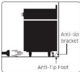
- To prevent accidental tipping of the range, attach an approved anti-tip device to the floor. (See Installing the Anti-Tip Device in the Installation Instructions.) Check for proper installation by carefully tipping the range forward. The anti-tip device should engage and prevent the range from tipping over.
- If the range is pulled out away from the wall for any reason, make sure the anti-tip device is reengaged after the range has been pushed back into place.
- Follow the installation instructions found in the Installation Manual. Failure to follow these instructions can result in death, serious personal injury, and / or property damage.
- DO NOT step / sit / lean on the door or drawer to prevent accidental tipping of the range.
Contents
Before you begin 4
About this manual 4
Important safety information 4
Read all instructions before using this appliance 4
Symbols used in this manual 4
California Proposition 65 Warning 5
Commonwealth of Massachusetts 5
General safety 5
Fire safety 6
Gas safety 6
Electrical and grounding safety 7
Installation safety 7
Location safety 8
Cooktop safety 8
Oven safety 9
Self-cleaning oven safety 10
Dual fuel range components 10
Dual fuel range specifications 10
Installation requirements 12
Location requirements 12
Installation guide 13
To remove safely from the pallet 14
To avoid breakage 14
Gas requirements 15
Special gas requirements (gas models sold in Massachusetts) 16
Electrical requirements 16
Tools and materials 18
What's in the box 18
Installation instructions 19
Installing your Dual fuel range 19
English 3
Before you begin
About this manual
Read these instructions completely and carefully.
Important note to the installer
- Read all instructions contained in these installation instructions before installing the range.
- Remove all packing materials from the oven compartments before connecting the electric and gas supply to the range.
- Observe all governing codes and ordinances.
- Be sure to leave these instructions with the consumer.
• Installation of this appliance requires basic mechanical skills.
• Proper installation is the responsibility of the installer. - Product failure due to improper installation is not covered under the Warranty.
Important note to the consumer
Keep these instructions with your user manual for future reference.
- As when using any appliance generating heat, there are certain safety precautions you should follow.
- Be sure your range is installed and grounded properly by a qualified installer or service technician.
- Make sure the wall coverings around the range can withstand the heat generated by the range.
- Cabinet storage space above the surface burners should be a minimum of 30 in (76.2 cm).
Important note to the servicer
The electrical diagram is in an envelope attached to the back of the range.
Important safety information
Read all instructions before using this appliance
- All electrical and gas equipment with moving parts can be dangerous. Please read the important safety instructions for this appliance in this manual. The instructions must be followed to minimize the risk of injury, death, or property damage.
- Save this manual. Please Do Not Discard.
Symbols used in this manual
WARNING
Hazards or unsafe practices that may result in severe personal injury or death.
CAUTION
Hazards or unsafe practices that may result in electric shock, personal injury or property damage
NOTE
Useful tips and instructions
These warning icons and symbols are here to prevent injury to you and others. Please follow them explicitly. After reading this section, keep it in a safe place for future reference.
4 English
California Proposition 65 Warning

WARNING
Cancer and Reproductive Harm - www.P65Warnings.ca.gov.
Commonwealth of Massachusetts
This product must be installed by a licensed plumber or gas fitter qualified or licensed by the State of Massachusetts. When using ball-type gas shut-off valves, you must use the T-handle type. Multiple flexible gas lines must not be connected in series.
General safety

WARNING
To reduce the risk of fire, electric shock, personal injuries, and/or death, obey the following precautions.
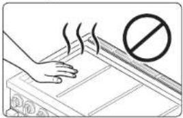
- Do not touch any part of the range, including but not limited to, oven burners, surface burners, or interior surfaces during or immediately after cooking.
-
Know the location of the gas shut-off valve and how to shut it off.
-
Make sure the anti-tip device is properly installed on the range. See the installation instructions for more information.
- Do not let children near, in, or on the range. Do not let children play with the range or any part(s) of the range. Do not leave children unattended in an area where the range is in use. For children's safety, we recommend utilizing the control/door lockout feature.
-
Remove all packaging materials from the range before operating to prevent ignition of these materials. Keep all packaging materials out of children's reach. Properly dispose the packaging materials after the range is unpacked.
-
Do not store any object of interest to children on the cooktop or backguard of the range. Children climbing on the range to reach items could be killed or seriously injured.
- Do not operate the range if the range or any part of the range is damaged, malfunctioning, or missing parts.
- Do not use the range as a space heater. This range is to be used for cooking purposes only.
- Do not use oven cleaners or oven liners in or around any part of the oven.
• Use only dry pot holders. - Do not use the range to heat unopened food containers.
- Do not strike the oven glass.
- When disposing of the range, cut off the power cord and remove the door.
• Unplug or disconnect power before servicing. - Make sure all meat and poultry is cooked thoroughly. Meat should always be cooked to an internal temperature of 160 °F (71 °C). Poultry should always be cooked to an internal temperature of 180 °F (82 °C).
English 5
Important safety information
Fire safety
WARNING
To reduce the risk of fire, electric shock, personal injuries, and/or death, obey the following precautions.
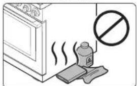
natural_image
Illustration of a kitchen with a bottle and cloth, emitting steam, accompanied by a prohibition symbol (no text or labels)- Do not store, place, or use flammable or combustible materials such as charcoal, paper, plastic, pot holders, linens, curtains, gasoline or other flammable vapors or liquids near or inside the range.
- Do not wear loose fitting or hanging garments while using the range.
• To avoid grease buildup, regularly clean the vents.
- Do not let pot holders or other flammable materials touch a heating element. Do not use a towel or other bulky cloths in place of a pot holder.
- Do not use water on a grease fire. To put out a grease fire, turn off the heat source and smother the fire with a tight-fitting lid or use a multipurpose dry chemical or foam-type fire extinguisher.
- If a grease fire should occur in the oven, turn off the oven by rotating the mode selector knob to the Off position. Keep the oven door closed until the fire goes out. If necessary, use a multipurpose dry chemical or foam-type fire extinguisher.
- Do not heat unopened food containers - buildup of pressure may cause container to burst and result in injury.
Gas safety
WARNING
To reduce the risk of fire, electric shock, personal injuries, and/or death, obey the following precautions.
If you smell gas:
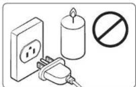
- Close the valve and do not use the range.
- Do not light a match, candle, or cigarette.
- Do not turn on any gas or electric appliances.
-
Do not touch any electrical switches or plug a power cord into an outlet.
-
Do not use any phone in your building.
• Evacuate the room, building, or area of all occupants. - Immediately call your gas supplier from a neighbor's phone. Follow the gas supplier's instructions.
- If you cannot reach your gas supplier, call the fire department.
Checking for gas leaks
Leak testing of the appliance shall be conducted according to the manufacturer's instructions. Do not use a flame to check for gas leaks. Use a brush to spread a soapy water mixture around the area you are checking. If there is a gas leak, you will see small bubbles in the soapy water mixture at the leak point.
6 English
Electrical and grounding safety

WARNING
To reduce the risk of fire, electric shock, personal injuries, and/or death, obey the following precautions.
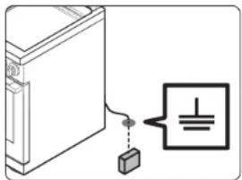
natural_image
Simple line drawing of a server unit connected to a battery with a symbol (no text or labels)- Plug into a grounded 3-prong outlet.
- Do not remove the ground prong.
- Do not use an adapter or an extension cord.
- Do not use a damaged power plug, power cord, or loose power outlet.
- Do not modify the power plug, power cord, or power outlet in any way.
- Do not put a fuse in a neutral or ground circuit.
- Use a dedicated 240-volt, 60-Hz, 50-amp, AC, fused electrical circuit for this range. A time-delay fuse or circuit breaker is recommended. Do not plug more than one appliance into this circuit.
- Do not connect the ground wire to plastic plumbing lines, gas lines, or hot water pipes.
- This range must be Earth grounded. In the event of a malfunction or breakdown, grounding will reduce the risk of electrical shock by providing a path for the electric current. This range is equipped with a cord having a grounding plug. The plug must be firmly plugged into an outlet that is properly installed and grounded in accordance with the local codes and ordinances. If you are unsure whether your electrical outlet is properly grounded, have it checked by a licensed electrician.
- Electrical service to the range must conform to local codes. Barring local codes, it should meet the latest ANSI/NFPA No. 70 - Latest Revision (for the U.S.) or the Canadian Electrical Code CSA C22.1 - Latest Revisions.
- It is the personal responsibility of the range owner to provide the correct electrical service for this range.
Installation safety

WARNING
To reduce the risk of fire, electric shock, personal injuries, and/or death, obey the following precautions.
natural_image
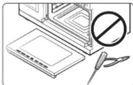
Illustration of a kitchen counter with a prohibition symbol (no text or labels)Have your range installed and properly grounded by a qualified Installer, in accordance with the installation instructions. Any adjustment and service should be performed only by qualified gas range installers or service technicians.
- Do not attempt to service, modify, or replace your range or any part of your range unless it is specifically recommended in this manual. All other service should be referred to a qualified technician.
- Always use new flexible connectors when installing a gas appliance. Do not use old flexible connectors.
• Make sure the anti-tip device is properly installed on the range. See the installation instructions for more information. - Due to the size and weight of the range, have two or more people move the range.
- Remove all tape and packaging materials.
- Remove all accessories from the cooktop and oven. Crates are heavy. Use caution when handling them.
• Make sure no parts came loose during shipping.
English 7
Important safety information
- Make sure your range is correctly installed and adjusted by a qualified service technician or installer for the type of gas (natural or LP) you will use. For your range to utilize LP gas, the installer must replace the 6 surface burner orifices and 2 oven orifices with the provided LP orifice set, and reverse the GPR adapter. These adjustments must be made by a qualified service technician in accordance with the manufacturer's instructions and all codes and requirements of the authority having jurisdiction. The qualified agency performing this work assumes the gas conversion responsibility.
- Installation of this range must conform with local codes or, in the absence of local codes, with the National Fuel Gas Code, ANSI Z223.1/NFPA.54, latest edition. In Canada, installation must conform with the current Natural Gas Installation Code, CAN/CGA-B149.1, or the current Propane Installation Code, CAN/CGA-B149.2, and with local codes where applicable. This range has been design-certified by ETL according to ANSI Z21.1, latest edition, and Canadian Gas Association according to CAN/CGA-1.1, latest edition.
Location safety

WARNING
To reduce the risk of fire, electric shock, personal injuries, and/or death, obey the following precautions.
natural_image
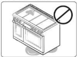
Illustration of a kitchen appliance with a prohibition symbol (no text or labels)- This range is for indoor, household use only. Do not install the range in areas exposed to the weather and/or water.
- Do not install the range in a place which is exposed to a strong draft.
- Select a level, well-constructed floor that can support the range's weight. Synthetic flooring, such as linoleum, must withstand 180 °F (82 °C) temperatures without shrinking, warping, or discoloring. Do not install the range directly over interior kitchen carpeting unless a sheet of ¼ inch plywood or a similar insulator is placed between the range and carpeting.
- Select a location where a grounded, 4-prong outlet is easily accessible.
- If the range is located near a window, do not hang long curtains or paper blinds on that window.
- For the range to ventilate properly, make sure the range's vents are not blocked or covered, and that there is enough clearance at the top, back, sides, and underneath the range. The vents allow the necessary exhaust for the range to operate properly with correct combustion and get the good cooking result.
- Make sure the wall coverings around the range can withstand heat up to 194 °F (90 °C) generated by the range.
- Cabinet storage above the surface of the range should be avoided. If cabinet storage above the range is necessary, allow a minimum clearance of 30 inches (76.2 cm) between the cooking surface and the bottom of cabinets. For detail information, please refer to the Minimum dimensions section on page 13.
Cooktop safety

WARNING
To reduce the risk of fire, electric shock, personal injuries, and/or death, obey the following precautions.
natural_image
Diagram of a device with a prohibition symbol (no text or labels present)• Make sure all burners are off when not in use.
- Do not use aluminium foil to line the grates or any part of the cooktop.
- Do not leave burners unattended on medium or high heat settings.
- Before igniting, make sure all burner caps are properly in place and all burners are level.
- Always use the Lite position when igniting the burners and make sure the burners have ignited. If ignition fails, turn the knob to Off and wait until the gas has dissipated.
- When you set a burner to simmer, do not turn the knob quickly. Make sure the flame stays on.
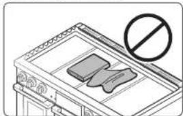
- Do not place any objects other than cookware on the cooktop.
- This cooktop is designed to cook with a wok or wok ring attachment. If foods are flamed, they should only be flamed under a ventilation hood that is on.
8 English
- Before removing or changing cookware, turn off the burners.
- Remove food and cookware immediately after cooking.
- Before removing any parts of the burner for cleaning, make sure the range is off and completely cool.
• After cleaning the burner spreader, make sure it is completely dry before reassembling.
• Make sure the spark mark on the dual burner spreader is placed beside the electrode when it is assembled. - To avoid carbon monoxide poisoning, do not pour water into the cooktop well while cleaning.
- Select cookware that is designed for top-range cooking. Use cookware that is large enough to cover the burner grates. Adjust the burner flames so that the flames do not extend beyond the bottom of the cookware.
- To avoid cookware discoloration, deformity, and/or carbon monoxide poisoning, do not use cookware that is exceedingly larger than the grate.
- Make sure cookware handles are turned to the side or rear of the cooktop, but not over other surface burners.
- Stand away from the range while frying.
- Always heat frying oils slowly, and watch as they heat. If you are frying foods at high heat, carefully watch during the cooking process. If a combination of fats or oils is to be used during frying, mix them together before heating.
- Use a deep-fryer thermometer whenever possible. This prevents overheating the fryer beyond the smoking point.
- Use a minimum amount of oil when shallow pan-frying or deep-frying. Avoid cooking unthawed food or food with excessive amounts of ice.
- Before moving cookware full of fats or oils, make sure it has completely cooled.
- To prevent delayed eruptive boiling, always allow heated liquids to stand at least 20 seconds after you have turned off the burner so that the temperature in the liquid can stabilize. In the event of scalding, follow these first aid instructions:
- Immerse the scaled area in cool or lukewarm water for at least 10 minutes.
- Do not apply any creams, oils, or lotions.
- Cover with a clean, dry cloth.
Oven safety
WARNING
To reduce the risk of fire, electric shock, personal injuries, and/or death, obey the following precautions.
natural_image
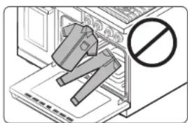
Diagram of a device with a prohibition symbol (no text or labels present)- Do not use the oven for non-cooking purposes such as drying clothes or storage. Use the oven for cooking purposes only.
- Make sure the inner portion of the split oven-rack is in the proper position within the outer rack.
• Make sure the oven racks are placed on the same level on each side.
- Do not damage, move, or clean the door gasket.
- Do not spray water on the oven glass while the oven is on or just after you have turned it off.
- Do not use aluminium foil or foil liners anywhere in the oven. Do not use aluminium foil or like material to cover any holes or passages in the oven bottom or to cover an oven rack.
- Stand away from the oven when opening the oven door.
- Keep the oven free from grease buildup.
- When repositioning the oven racks, make sure the oven is completely cool.
- To avoid damaging the burner control knobs, always bake and/or broil with the oven door closed.
- Do not broil meat too close to the burner flame (or heater). Trim excess fat from meat before cooking.
- When using cooking or roasting bags in the oven, follow the manufacturer's directions.
English 9
Important safety information
Self-cleaning oven safety

WARNING
To reduce the risk of fire, electric shock, personal injuries, and/or death, obey the following precautions.
natural_image
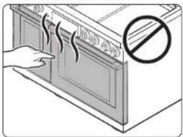
Illustration of a hand opening a kitchen appliance with a prohibition symbol (no text or labels)The self-cleaning feature operates the oven at temperatures high enough to burn away food soils in the oven. The range is extremely hot during a self-cleaning cycle. Do not touch any surfaces of the range during a self-cleaning cycle.
- Keep children away from the oven during a self-cleaning cycle.
- Before starting a self-cleaning cycle, remove all racks, cookware, and utensils from the oven. Only porcelain-coated oven racks may be left in the oven.
- Before starting a self-cleaning cycle, wipe grease and food soils from the oven.
- When opening the door after a self cleaning cycle, stand away from the oven.
- If the self-cleaning cycle malfunctions, turn off the oven, disconnect the power supply, and contact a qualified service technician.
Dual fuel range components
Dual fuel range specifications
MODEL DOP48*96*D*
| Description Dual fuel Range | |
| Overall dimensions 47 18 in (W) × 37 14 in (H) × 29 12 in (D)1216 mm (W) × 946 mm (H) × 750 mm (D) | |
| Electrical Refer to the rating label. | |
| Gas, ng (natural gas) 5 - 13 in WC | |
| Gas, Ip (liquid propane) 10 - 13 in WC | |
| Surface burners (NG)DOP48*960D* | (LF) - 22,000 BTU / (LR) - 16,000 BTU(RF) - 22,000 BTU / (RR) - 9,000 BTU(CF) - 16,000 BTU / (CR) - 16,000 BTU |
| Surface burners (LP)DOP48*960D* | (LF) - 16,000 BTU / (LR) - 15,000 BTU(RF) - 16,000 BTU / (RR) - 9,500 BTU(CF) - 15,000 BTU / (CR) - 15,000 BTU |
| Burner Location (NG)DOP48*963D* | (LF) - 18,000 BTU / (LR) - 16,000 BTU(RF) - 16,000 BTU / (RR) - 16,000 BTU(CF) - 22,000 BTU / (CR) - 9,000 BTU |
| Burner Location (LP)DOP48*963D* | (LF) - 16,000 BTU / (LR) - 15,000 BTU(RF) - 15,000 BTU / (RR) - 15,000 BTU(CF) - 16,000 BTU / (CR) - 9,500 BTU |
| Oven heater 36" Convection - 1,300 W + 1,300 W36" Broil - 4,400 W36" Bake - 3,000 W12" Convection - 1,300 W12" Broil - 2,400 W12" Bake - 1,000 W | |
10 English
DOP48*960D* DOP48*963D*
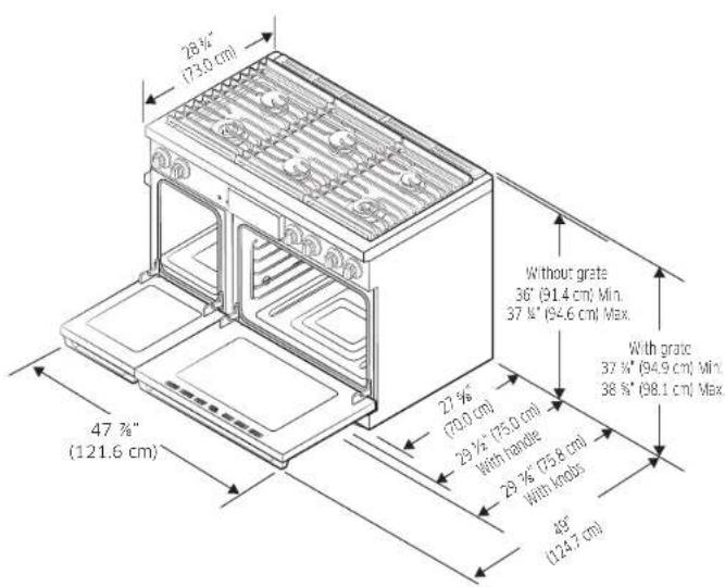
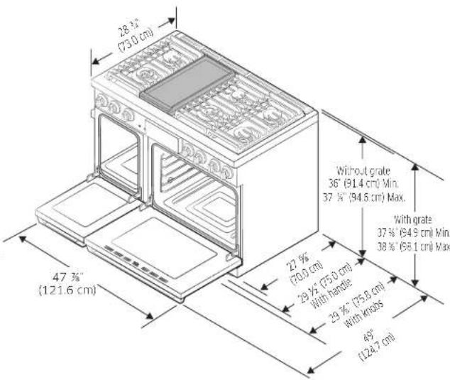
Dual fuel range components
English 11
Installation requirements
Location requirements
Clearances and dimensions
NOTE
- For QTR over Gas Stove, please follow local GAS CODE.
- BEFORE YOU BEGIN to install this appliance, refer to the following information, dimensions, and clearances. Do not locate the range where it may be subject to strong drafts. Provide adequate clearances between the range and adjacent combustible surfaces. These dimensions must be met for safe use of the range. The location of the electrical outlet and gas piping may be adjusted to meet the following dimensions and clearances.
- For installation in Canada, a free-standing range is not to be installed closer than 4.7 in (12 cm) from any adjacent surface.
- Installations without a hood require 48" minimum to combustibles. A custom hood installation with exposed horizontal combustible surfaces must have an Auto On feature. Refer to hood installation instructions for specific hood clearances.
CAUTION
This range has been designed to comply with the maximum allowable wood cabinet temperature of 194 °F (90 °C). Make sure the wall covering, countertops, and cabinets around the range can withstand the heat (up to 194 °F [90 °C]) generated by the range. If not, discoloration, delamination, or melting may occur.
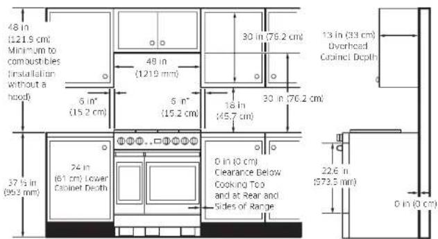
* Side clearance above cooking surface to any objects, i.e., wall.
12 English
Minimum dimensions
CAUTION
- If overhead cabinets are installed, a range hood should also be installed and project horizontally a minimum of 5" (12.7 cm) beyond the front of the cabinets. Hood is necessary to dissipate any heat buildup in the overhead cabinets to prevent possibility of fire, personal injury and/or death. The ventilating hood must be constructed of sheet metal not less than 0.0122" thick and installed above the cooktop with a clearance of not less than ¼" between the hood and the underside of the combustible material or metal cabinet. The hood must be at least as wide as the appliance and centered over the appliance. Clearance between the cooking surface and the ventilation hood surface must never be less than 24".
- Exception 1: Installation of a listed microwave oven or cooking appliance over the cooktop shall conform to the installation manual provided with the appliance.
30" (76.2 cm) minimum clearance between the top of the cooking surface and the bottom of an unprotected wood or metal cabinet; or if 30" (76.2 cm) clearance is not possible, minimum of 24" (61 cm) can be used when the bottom of the wood or metal cabinet is protected by not less than ¼" (0.64 cm) flame-retardant millboard covered with not less than no. 28 MSG sheet steel, 0.015" (0.038 cm) stainless steel, 0.024" (0.061 cm) aluminum, or 0.020" (0.051 cm) copper.
18" (45.7 cm) of minimum clearance between the countertop and the adjacent cabinet bottom.
- Exception 2: For island installation, maintain 2 12 minimum from cutout to back edge of countertop and 4 minimum from cutout to side edges of countertop.
Installation guide
Recommended locations for gas piping and electrical outlets
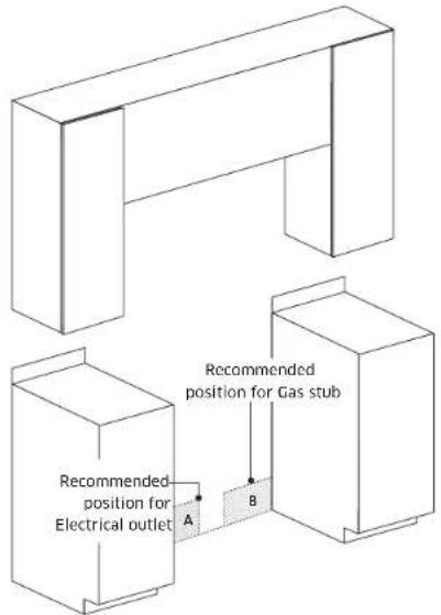
| Model DOP48°96"D* | |
| A | Electrical outlet 9^7/_8''(W) × 6^7/_8''(H) (25.1 cm x 17.5 cm) |
| B | Gas piping 17^13/_15''(W) × 5^3/_8''(H) (45.5 cm x 13.8 cm) |
English 13
Installation requirements
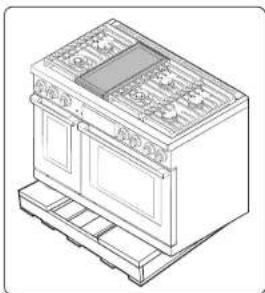
To remove safely from the pallet
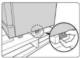
natural_image
Technical diagram showing a mechanical assembly with an inset close-up of a component detail (no text or symbols visible)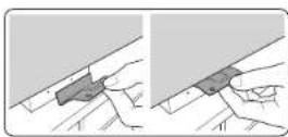
natural_image
Line drawing of a vintage kitchen appliance with cabinetry and grilles (no text or symbols)-
Remove the screws from the bottom bracket on either side and rear side of the unit.
-
Press the bracket on either side to pull out.
-
Remove pallet and packing material. Use caution not to hold the door handle.
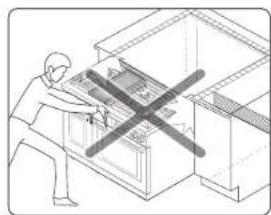
To avoid breakage
natural_image
Illustration of a person using a computer with a 'X' symbol crossed out, no text or symbols present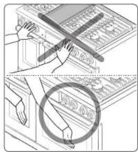
CAUTION
- Please DO NOT push the unit strongly when you install. These actions can cause the damage to the unit.
- Hold the upper left/right area of the door (not the door handle) with both hands and push the unit in. Do not grab the door handle.
14 English
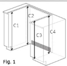
- The counter top around the cut-out should be flat and leveled (see hatched area on Fig. 1).
- Before installing the unit, measure the heights of the two cabinet sides (C1–C4), front and back (See Fig. 1) from the floor to the top of the counter.
- Level the range using the four leveling legs so that the height from the floor to the top of the cooktop frame is level with a countertop.
- Slide the unit into the cabinet (DO NOT PUSH THE UNIT HARD). Make sure the center of the unit aligns with the center of the cabinet cut-out.
Gas requirements
Provide adequate gas supply
This range is designed to operate at a pressure of 5 in (13 cm) of water column on natural gas or 10 in (25 cm) of water column on LP gas (propane or butane). Make sure you are supplying your range with the type of gas for which it is designed.
Do not attempt to convert the appliance from the gas specified in this manual to a different gas without consulting the gas supplier.
This range is convertible for use on natural or propane gas. If you decide to use this range on LP gas, conversion must be made by a qualified LP installer before attempting to operate the range.
For proper operation, the pressure of natural gas supplied to the regulator must be between 6 in and 13 in (13 cm and 33 cm) of water column.
For LP gas, the pressure supplied must be between 11 in and 13 in (25 cm and 33 cm) of water column.
When checking for proper operation of the regulator, the inlet pressure must be at least 1 in (2.5 cm) greater than the operating (manifold) pressure as given.
The pressure regulator located at the inlet of the range manifold must remain in the supply line regardless of whether natural or LP gas is being used.
A flexible-metal appliance connector used to connect the range to the gas supply line should have an I.D. of 0.5 in (1.3 cm) and be 5 ft (152 cm) in length for ease of installation. In Canada, flexible connectors must be single-wall metal connectors no longer than 6 ft (183 cm) in length.
Do not kink or damage the flexible metal tubing when moving the range.
English 15
Installation requirements
Special gas requirements (gas models sold in Massachusetts)
COMMONWEALTH OF MASSACHUSETTS REQUIREMENTS:
WARNING
- Gas leaks may occur in your system, creating a dangerous situation. Gas leaks may not be detected by smell alone.
- Gas suppliers recommend you purchase and install a UL-approved gas detector. Gas detector should be installed in accordance with the manufacturers instructions.
- Range must be installed by a qualified plumber or gas fitter by the State of Massachusetts.
- A T-handle manual gas valve MUST be installed in the gas supply line to your range.
- If a flexible gas connector is used to install your range, multiple flexible gas lines must not be connected in series.
Electrical requirements

WARNING
To reduce the risk of fire, electric shock, or personal injury:
All ranges
- Do not use an extension cord or adapter plug with this range.
• This range must be properly grounded. - Check with a qualified electrician if you are in doubt as to whether your range is properly grounded.
- All wiring and grounding must be done in accordance with local codes or, in the absence of local codes, with the National Electrical Code, ANSI/NFPA No. 70 – Latest Revision (for the U.S.) or the Canadian Electrical Code CSA C22.1 – Latest Revisions and local codes and ordinances.
- Wiring diagram is located on the back of the range. (Inside of the cover back wire)
- This range is equipped with an electronic ignition system that will not operate if plugged into an outlet that is not properly polarized.
Dual fuel models
- A 240 Volt. 60 Hz, AC, approved electrical service with 50 amp circuit breaker or time-delay fuse is required for all U.S. and Canadian models.
- Check for 14 -in (1.9-cm) UL-listed strain relief where the power cord comes out of the range cabinet.
- Do not reuse a power supply cord from an old range or other appliance.
- The power cord electric supply wiring must be retained at the range cabinet with a suitable UL-listed strain relief.
- A time-delay fuse or circuit breaker is also recommended.
16 English
Grounding
- All ranges must be grounded for personal safety.
- The plug must be firmly plugged into a 3-prong or 4-prong outlet that is properly installed and grounded in accordance with all local codes and ordinances. In the event of a malfunction or breakdown, grounding will decrease the risk of electrical shock by providing a path for the electric current.
- Do not use a damaged power plug or loose wall outlet.
- Do not use an extension cord or adapter with this appliance.
- Do not, under any circumstances, cut, modify, remove, or otherwise defeat the grounding if quipped. If the plug and the outlet do not match or you have any doubt, have a qualified electrician install the proper outlet.
The customer should have the wall receptacle and circuit checked by a qualified electrician to make sure the receptacle is properly grounded. Ground Fault Circuit Interrupters(GFCIs) are not required or recommended for range receptacles.
- NEVER connect ground wire to plastic plumbing lines, gas lines, or water pipes.

CAUTION
Failure to follow these instructions can result in death, fire, or electrical shock.
Usage situations where appliance power cord will be disconnected frequently
Do not use an adapter plug in these situations because disconnecting of the power cord places under strain on the adapter and leads to eventual failure of the adapter ground terminal. 240 V plug have 3 or 4 prongs and are not supplied with a unit.
Additional installation requirements for mobile homes
The installation of appliances designed for mobile home installation must conform with the Manufactured Home Construction and Safety Standard, Title 24 CFR, Part 3280 (formerly the Federal Standard for Mobile Home Construction and Safety. Title 24. HUD, Part 280) or, when such standard is not applicable, the Standard for Manufactured Home Installations, latest edition (Manufactured Home Sites, Communities and Set-Ups), ANSI A225.1, latest edition, or with local codes. In Canada, mobile home installation must be in accordance with the current CAN/CSA Z240/MH Mobile Home Installation Code.
Power cord location

natural_image
Pure technical diagram of a mechanical component with no text, numbers, or symbolsThe power cord for this appliance is located on the back of the range, near the bottom left corner.
English 17
Tools and materials
What's in the box
Parts supplied
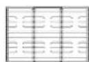
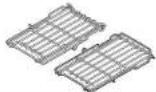
Grates (3) Burner heads (6) and
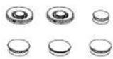
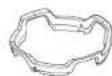
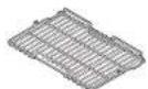
Wire rack (1)
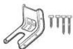
Anti-tip bracket kit Wok ring (1) Gliding racks (2)
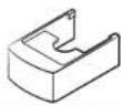
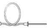
Temp. Probes (2) Front leg covers (3) Brass burner caps (8)

Convection filters (3) Air Fry tray (1) Small racks (2)
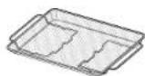
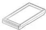
Griddle (1)*
* DOP48^963*D model only.
18 English
NOTE
• Make sure you have received all of the supplied parts shown above.
- If your range was damaged during shipping or you do not have all of the supplied parts, contact your local retailer.
Parts needed

Gas line shut-off valve
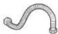
Flexible metal appliance connector 12 " (ID) x 5 ft

Flare union adapter 34 " or 12 " (NPT) x 12 " (ID)
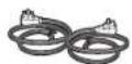
4-wire cord or 3-wire cord

Flare union adapter 12 " (NPT) x 12 " (ID)

135-degree elbow (optional)

Lag bolt or 1½ (OD) sleeve anchor
Tools needed

Flat-blade screwdriver

Phillips screwdriver
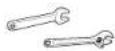
Open-end or adjustable wrench

Pipe wrenches (2)

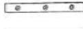
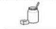

Nut driver
Pencil and ruler Level Pipe joint

Utility knife Soapy water solution

compound
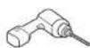
Drill with 18 " or 316 " bit
Installation instructions
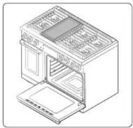
Installing your Dual fuel range

NOTE
- IMPORTANT: Please read the following instructions, as well as the Important Safety Instructions section at the front of this manual, completely and carefully BEFORE installing and/or operating the dual fuel range. Improper installation, adjustment, service, or maintenance can cause personal injury or property damage.
natural_image
Line drawing of an oven with doors open and a side panel on top (no text or symbols)• To order parts or accessories, contact your local retailer or refer to the last page.
• To ensure proper installation, we strongly recommend that you hire a professional installer.
Step 1. Unpack the range
Remove all packaging materials. Failure to remove packaging materials could result in damage to the appliance.
Inventory all loose parts against the 'Parts supplied' overview on page 18. Check for shipping damage and/or missing parts. Any damage and/or missing parts should be reported to your local retailer.
Step 2. Meeting electrical connection requirements

CAUTION
For personal safety, do not use an extension cord with this appliance. Remove house fuse or open circuit breaker before beginning installation.
This appliance must be supplied with the proper voltage and frequency, and connected to an individual properly grounded branch circuit, protected by a circuit breaker or fuse having amperage as specified on the rating plate. The rating plate is located below the control chassis on the oven frame.
We recommend you have the electrical wiring and hookup of your range connected by a qualified electrician. After installation, have the electrician show you where your main range disconnect is located.
Check with your local utilities for electrical codes which apply in your area. Failure to wire your oven according to governing codes could result in a hazardous condition.
If there are no local codes, your range must be wired and fused to meet the requirements of the National Electrical Code, ANSI/NFPA No. 70-Latest Edition. You can get a copy by writing:
National Fire Protection Association
Batterymarch Park
Quincy, MA 02269
Effective January 1, 1996, the National Electrical Code requires that new construction (not existing) utilize a 4-conductor connection to an electric range. When installing an electric range in new construction, follow Steps 2 and 3 for 4-wire connection.
You must use a 3-wire or 4-wire, single-phase A.C. 208/120 Volt or 240/120 Volt, 60 hertz electrical system.
If the electrical service provided does not meet the above specifications, have a licensed electrician install an approved outlet.
Use only a 3-conductor or a 4-conductor UL-listed range cord. These cords may be provided with ring terminals on wire and a strain relief device.
A range cord rated at 40 amps with 125/250 minimum volt range is required.
English 19
Installation instructions
A 50 amp range cord is not recommended but if used, it should be marked for use with nominal 1 ^3/8 " diameter connection openings. Care should be taken to center the cable and strain relief within the knockout hole to keep the edge from damaging the cable.
Because range terminals are not accessible after range is in position, flexible service conduit or cord must be used.

NOTE
If conduit is being used, go to Step 5 on pages 22-23.

ALL NEW BRANCH-CIRCUIT CONSTRUCTIONS, MOBILE HOMES, RECREATIONAL VEHICLES AND INSTALLATIONS WHERE LOCAL CODES DO NOT ALLOW GROUNDING THROUGH NEUTRAL, REQUIRE A 4-CONDUCTOR UL-LISTED RANGE CORD.
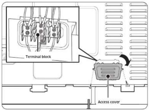
Step 3. Accessing the power cord connection
Remove the rear access cover and loosen the screw with a screwdriver. The terminal block will then be accessible.
20 English
Specified power-supply-cord kit rating
| Range rating, watts | Specified rating of power-supply cord kit, amperes | Diameter (inches) of range connection opening | ||
| 120/240 volts 3-wire | 120/208 volts 3-wire | Power cord | Conduit | |
| 8750 - 16500 | 7801 - 12500 | 40 or 50 A 112 " 112 " | ||
Step 4. Installing the power cord
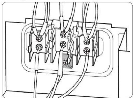
For power cord installations, hook the strain relief over the power cord hole (1%") located below the rear of the drawer body. Insert the power cord through the strain relief and tighten the device.
natural_image
Pure electrical circuit lines without any symbols- You must install the power cord with a strain relief.
- Attach the strain relief to the 1 12 opening in conduit connection plate.
Installing a 3-wire power cord
WARNING
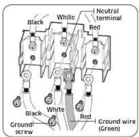
The neutral or ground wire of the power cord must be connected to the neutral terminal located in the center of the terminal block. The power leads must be connected to the lower left and the lower right terminals of the terminal block.
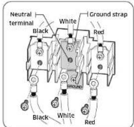
- Remove the 3 lower terminal screws from the terminal block.
- Insert the 3 terminal screws through each power cord terminal ring and into the lower terminals of the terminal block. Be certain that the center wire (white/neutral) is connected to the center lower position of the terminal block.
- Tighten screws securely into the terminal block, DO NOT remove the ground strap connection.
- Go to Step 6 on page 23 and proceed with the installation.
Installing a 4-wire power cord
WARNING
The neutral wire of the supply circuit must be connected to the neutral terminal located in the lower center of the terminal block. The power leads must be connected to the lower left and the lower right terminals of the terminal block. The 4th grounding lead must be connected to the frame of the range with the ground plate and the ground screw.
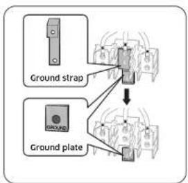
- Remove the 3 lower terminal screws from the terminal block. Remove the ground screw and ground plate and retain them.
- Cut and discard the ground strap. Do not discard any screws.
- Insert the one ground screw into the power cord ground wire terminal ring, through the ground plate, and into the frame of the range.
- Insert the 3 terminal screws (removed earlier) through each power cord terminal ring and into the lower terminals of the terminal block. Be certain that the center wire (white/neutral) is connected to the center lower position of the terminal block. Tighten screws securely into the terminal block.
- Go to Step 6 on page 23 and proceed with the installation.
English 21
Installation instructions
Step 5. Installing the conduit
Remove the conduit connection plate from the rear of the drawer body and rotate it as shown below.
The conduit hole (1½") must be used.
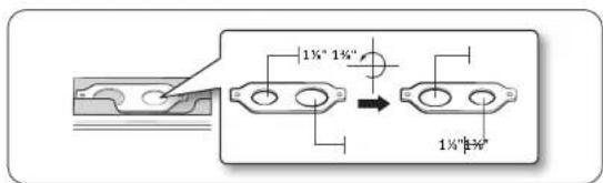
- Prepare the conduit cord shown in Figure 1.
- Install the conduit cord as shown in Figure 2.
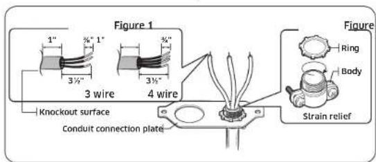
For conduit installations, insert the strain relief (not included) into the conduit hole (1½"). Then thread the conduit cord through the body of the strain relief and fasten the ring. Reinstall the bracket.
Installing a 3-wire conduit
- Aluminum building wire may be used but it must be rated for the correct amperage and voltage to make the connection. Connect wires according to Step 4 depending on the number of wires.
- Wire used, location and enclosure of splices, etc., must conform to good wiring practices and local codes.
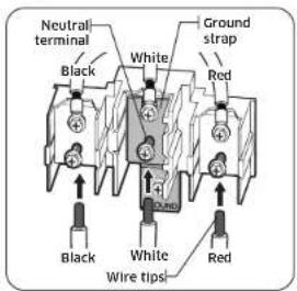
- Loosen the 3 lower terminal screws from the terminal block.
- Insert the center bare wire (white/neutral) tip through the bottom center terminal block opening. On certain models, the wire will need to be inserted through the ground strap opening and then into the bottom center block opening.
- Insert the two side bare wire tips into the lower left and the lower right terminal block openings.
- Tighten the screws until the wire is firmly secured (35 to 50 inch-lbs). Do not over-tighten the screws since it could damage the wires.
- Go to Step 6 on page 23 and proceed with the installation.
22 English
Installing a 4-wire conduit
- Aluminum building wire may be used but it must be rated for the correct amperage and voltage to make the connection. Connect wires according to this Step 4 depending on the number of wires.
- Wire used, location and enclosure of splices, etc., must conform to good wiring practices and local codes.
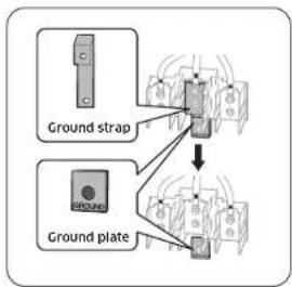
flowchart
graph TD
    A["Ground strap"] --> B["Top panel"]
    C["Ground plate"] --> B
    B --> D["Output"]
- Loosen the 3 lower terminal screws from the terminal block. Remove the ground screw and ground plate and retain them.
- Cut and discard the ground strap. Do not discard any screws.
- Insert the ground bare wire tip between the range frame and the ground plate (removed earlier) and secure it in place with the ground screw (removed earlier).
- Insert the bare wire (white/neutral) tip through the bottom center of the terminal block opening.
- Insert the two side bare wire tips into the lower left and the lower right terminal block openings.
- Tighten the screws until the wire is firmly secured (35 to 50 inch-lbs.). Do not over tighten the screws since it could damage the wires.
- Go to Step 6 and proceed with the installation.
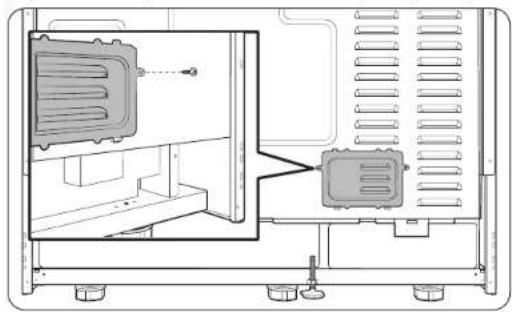
Step 6. Replacing the access cover
Replace the access cover on the range back. To replace the wire cover, insert double projections in the pockets located below the opening and tighten the screw.
natural_image
Technical line drawing of an electrical enclosure showing internal components and wiring (no text or symbols)
English 23
Installation instructions
Step 7. Connect the range to gas supply
Shut off the main gas supply valve before disconnecting the old range and leave it off until the new hookup has been completed. Don't forget to relight the pilot on other gas appliances when you turn the gas back on.
Because hard piping restricts movement of the range, the use of a CSA International-certified flexible metal appliance connector is recommended unless local codes require a hard-piped connection.
WARNING
If the information in this manual is not followed exactly, a fire or explosion may result, causing death, personal injury, or property damage.
-
Do not store or use gasoline or other flammable vapors and liquids in the vicinity of this or any other appliance.
• WHAT TO DO IF YOU SMELL GAS: -
DO NOT light a match, candle, or cigarette.
- DO NOT try to light any appliance.
- DO NOT touch any electrical switch.
- DO NOT use any phone in your building.
- Clear the room, building, or area of all occupants.
- Immediately call your gas supplier from a neighbor's phone. Follow the gas supplier's instructions.
If you cannot reach your gas supplier, call the fire department.
- Installation and service must be performed by a qualified installer, service agency, or gas supplier.
Never use an old connector when installing a new range. If the hard-piping method is used, you must carefully align the pipe; the range cannot be moved after the connection is made.
To prevent gas leaks, apply pipe-joint compound or wrap pipe-thread tape with Teflon on all male (external) pipe threads.
- Install a manual gas line shut-off valve in the gas line in an easily accessed location outside of the range. Make sure everyone operating the range knows where and how to shut off the gas supply to the range.
- Install male 0.5 in (1.3 cm) flare union adapter to the 0.5 in (1.3 cm) NPT internal thread at the regulator inlet. Use a backup wrench on the regulator fitting to avoid damage. When installing the range from the front, remove the 90° elbow for easier installation.
- Install male 0.5-in (1.3-cm) or 0.75-in (1.9-cm) flare union adapter to the NPT internal thread of the manual shut-off valve, taking care to back up the shut off valve to keep it from turning.
- Connect flexible metal appliance connector to the adapter on the range. Position range to permit connection at the shut-off valve.
- When all connections have been made, make sure all range controls are in the off position and turn on the main gas supply valve. Use a liquid leak detector at all joints and connections to check for leaks in the system.
WARNING
To prevent death, personal injury, explosion, and/or fire hazard, DO NOT use a flame to check for gas leaks.
When using test pressures greater than 12 psig to pressure test the gas supply system of the residence, disconnect the range and individual shut-off valve from the gas supply piping. When using test pressures of 12 psig or less to test the gas supply system, simply isolate the range from the gas supply system by closing the individual shut-off valve.
24 English
WARNING
Do not exceed 25 ft-lbs of torque when making gas line connections. Overtightening may crack the pressure regulator resulting in gas leak.
Flexible connector hookup
Installer: Inform the consumer of the location of the gas shut-off valve.
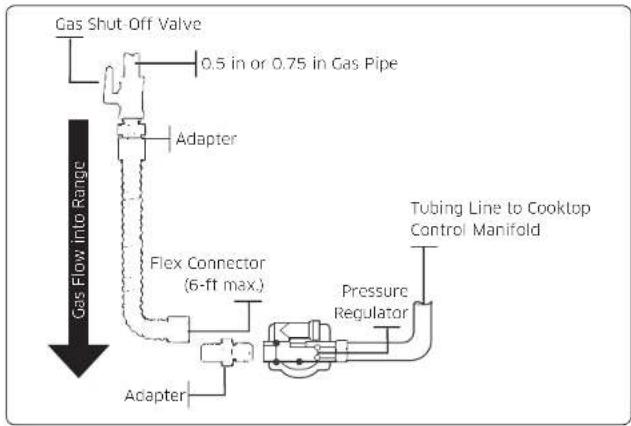

NOTE
- If your area requires a rigid pipe hookup, contact a qualified installer, service agency, or gas supplier.
- The gas shut-off valve should be installed in an accessible location in the gas piping, external to the appliance, for the purpose of turning on or shutting off the gas to the appliance.
Step 8. Convert to Ip gas (optional)
All new dual fuel ranges are shipped from the factory set up to use natural gas. This Dacor dual fuel ranges can be converted to use LP gas. (Contact a qualified service technician.)
The conversion process should only be performed by a qualified LP gas installer. Conversion instructions and LP orifices will be supplied with the LP conversion kit. The conversion to LP requires all burner orifices to be changed (6 surface burners and 2 oven burners).
In addition, the nozzle on the gas pressure regulator needs to be reversed. All replaced orifices must be left with the consumer, including the instructions and retrofit sizes and orifice indication.
DOP48*960D*
| BURNER ORIFICE SIZES AND OUTPUT RATINGS(LP Gas [Propane] 10 In WCP) | ||
| Burner Location | BTU Rate Orifice Size [mm] | |
| LF 16,000 | In 0.46 / Out 0.78*2 | |
| LR 15,000 | 1.04 / 0.50 | |
| RF 16,000 | In 0.46 / Out 0.78*2 | |
| RR 9,500 | 0.78 / 0.50 | |
| CF 15,000 | 1.04 / 0.50 | |
| CR 15,000 | 1.04 / 0.50 | |
| BURNER ORIFICE SIZES AND OUTPUT RATINGS(Natural Gas 5 in WCP) | ||
| Burner Location | BTU Rate Orifice Size [mm] | |
| LF 22,000 | In 0.85 / Out 1.36*2 | |
| LR 16,000 | 1.60 / 0.68 | |
| RF 22,000 | In 0.85 / Out 1.36*2 | |
| RR 9,000 | 1.20 / 0.61 | |
| CF 16,000 | 1.60 / 0.68 | |
| CR 16,000 | 1.60 / 0.68 | |
English 25
Installation instructions
DOP48*963D*
| BURNER ORIFICE SIZES AND OUTPUT RATINGS(LP Gas [Propane] 10 in WCP) | ||
| Burner Location | BTU Rate Orifice Size [mm] | |
| LF 16,000 | In 0.46 / Out 0.78*2 | |
| LR 15,000 | 1.04 / 0.50 | |
| RF 15,000 | 1.04 / 0.50 | |
| RR 15,000 | 1.04 / 0.50 | |
| CF 16,000 | In 0.46 / Out 0.78*2 | |
| CR 9,500 | 0.78 / 0.50 | |
| BURNER ORIFICE SIZES AND OUTPUT RATINGS(Natural Gas 5 in WCP) | ||
| Burner Location | BTU Rate Orifice Size [mm] | |
| LF 18,000 | In 0.70 / Out 1.27*2 | |
| LR 16,000 | 1.60 / 0.68 | |
| RF 16,000 | 1.60 / 0.68 | |
| RR 16,000 | 1.60 / 0.68 | |
| CF 22,000 | In 0.85 / Out 1.36*2 | |
| CR 9,000 | 1.20 / 0.61 | |
Step 9. Install the anti-tip device
WARNING
- To reduce the risk of tipping, the appliance must be secured by properly installing the anti-tip device packed with the appliance.
- All ranges can tip, resulting in personal injury.
- Tipping ranges can cause burns from spills, personal injury, and/or death.
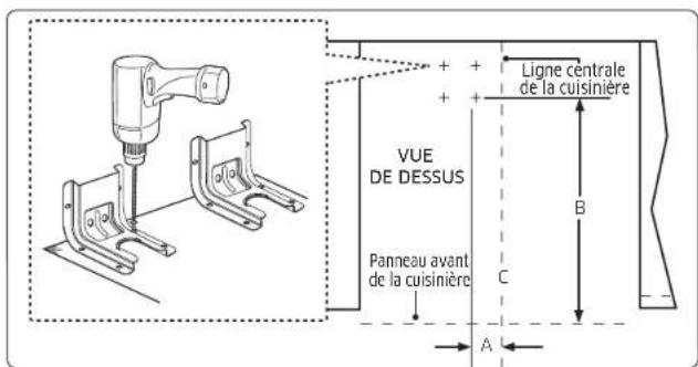
- To prevent accidental tipping, install and check the anti-tip bracket following the instructions and template supplied with the bracket.
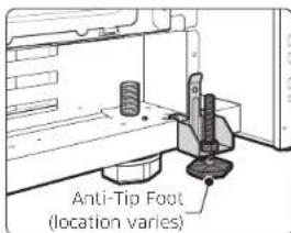
An anti-tip bracket and screws, installation instructions, and template are shipped with every range (PN 114475). The instructions include information necessary to complete the installation of the anti-tip bracket. Read and follow the instructions on the sheet and use the template for anti-tip bracket installation. If not properly installed, the range could be tipped by you or a child standing, sitting, or leaning on an open oven door.
26 English
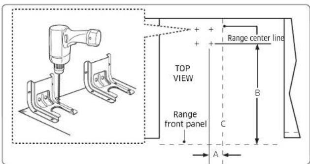
- If bracket is to be mounted to wood floor, use a drill with a 1/8" drill bit to drill the four holes. If bracket is to be mounted to cement or ceramic floor, use a drill with a 3/16" drill bit to drill the four holes.
| ANTI-TIP BRACKET PLACEMENT |
| Dim. DOP48*96*D* |
| A 6 1/4" (15.9 cm) |
| B 23 7/8" (60.7 cm) |
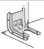
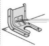
Option 1
(Using the short
2 screws.)
Option 2
(Using the long
2 screws.)
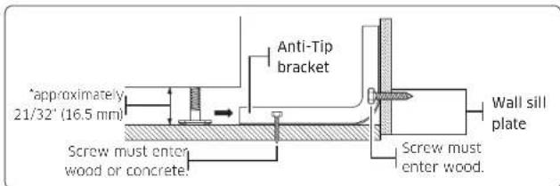
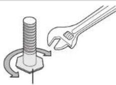
- Level range by adjusting the leveling legs with a wrench. Use a spirit level to check your adjustments. Plug the power supply cord into the grounded outlet. Slide range back into position. To check visually that rear leveling leg is inserted into bracket, grasp the top rear edge of the range and carefully attempt to tilt it forward.
natural_image
Illustration of a wrench turning a bolt with a curved arrow indicating rotation (no text or symbols)Leveling leg
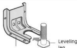
Anti-Tip bracket
NOTE
To install the Anti-tip bracket, release the leveling leg using pipe wrench because Loctite is applied on Bolt for vibration unlocking. A minimum clearance of 316 (35.1 mm) is required between the range bottom and the kitchen floor. To check if the bracket is installed and engaged properly, remove the kick panel and look underneath the range to see that the leveling leg is engaged in the bracket. Carefully tip the range forward. The bracket should stop the range within 4 inches (10.2 cm) of tipping. If it does not, the bracket must be reinstalled. If the range is pulled from the wall for any reason, always repeat this procedure to verify the range is properly secured by the anti-tip bracket. Never completely remove the leveling legs or the range will not be secured to the anti-tip device properly.
English 27
Installation instructions
Step 10. Plug in and place
WARNING
- BEFORE OPERATING OR TESTING, follow the grounding requirements on pages 16-17 in this manual. Improper connection of the grounding plug can result in a risk of electric shock.
Please review "Electrical requirements" on pages 16-17. - Altering any part of this system may result in a short or overload.
- Plug in the power cord. Make sure the outlet meets local or national electrical codes as referenced on pages 16-17.
- Slide the range into place.
- Check the gas supply line to make sure it did not get damaged and it stayed connected during positioning.
- Check to make sure the back leg of the range has slid into the anti-tip bracket. Carefully tip the range forward to ensure that the anti-tip bracket engages the back brace and prevents tip-over.
NOTE
If the power cord is plugged in improperly, the following message appears on the display.
• LCD, PMOLED: Wire installation fail
- LED : bAd LinE
Reconnect the power cord properly, and the message disappears. Step 11. Moving and placing the range
Step 11. Moving and placing the range
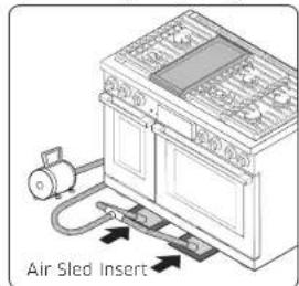
- Due to the weight, heavy equipment movers such as Air Sled should be used to move this unit. The weight must be supported uniformly across the bottom.
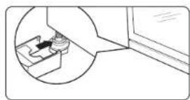
- After transporting the range by Air Sled where you want, the range can be leveled by adjusting the legs with a wrench while Air Sled is supported. Using a wrench, level the range by turning the front leveling legs in or out as necessary. Counterclockwise shortens the leg and lowers the range. Clockwise lengthens the leg and raises the range.
NOTE
Adjust the leveling legs only as far as necessary to level the range. Extending the leveling legs more than necessary or removing legs can cause the range to be unstable.
natural_image
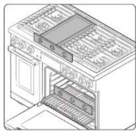
Line drawing of an open kitchen appliance with grilles and a stove (no text or symbols)- If range is next to or between cabinets, make sure the cooktop (without the surface burner grates) is level with the countertops.
- Position an oven rack in the center rack position.
- Check the level of the range with a carpenter level using the two positions shown on the left.
- After the range becomes level, Use Air Sled to move the range away from the wall so that the anti-tip bracket can be installed.
- After installing and leveling the range, carefully remove Air Sled and install front leg covers (right, center and left).
28 English
Step 12. Assemble the surface burners

CAUTION
Do not operate the surface burners without all burner parts in place.
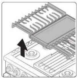
- Position surface burner heads on top of the surface burner manifolds as shown in the picture on the right. The electrodes will fit into the slot in the bottom of the heads. Make sure the surface burner heads are flat and parallel with the cooktop.
- Place the matching size caps on top of each surface burner head.
| Top Bottom | |
natural_image
Technical diagram of a mechanical assembly with no visible text or symbols- Place the left and right surface burner grates on the cooktop. The edges of the grates should match up with the edges of the cooktop.
NOTE
- Grates should be placed on its own position because they are not interchangeable.
- You can recognize the right position of the grates by checking the bottom side of each. Look for engraved position on right and left grate, RIGHT FRONT and LEFT FRONT respectively.
- The grates are heavy. Be careful while handling the grates.
Step 13. Check the ignition of surface burners and oven burners
Check the operation of all cooktop and oven burners after the range has been installed and assembled, gas supply lines have been carefully checked for leaks, and electrical power cord has been plugged in.
All surface and oven burners have electronic ignition.
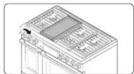
To turn on a surface burner:
natural_image
Technical line drawing of a mechanical or electrical component with no visible text or symbols- Push in the control knob, and then turn it to the Lite position. You will hear a 'clicking' sound indicating the electronic ignition system is working properly.
- Turn the control knob to adjust the flame level.
English 29
Installation instructions
Checking the flame quality:
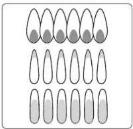
All combustion flames need to be visually checked to determine their flame quality.
natural_image
Illustration of ten identical teardrop-shaped objects arranged in a grid, with no text or symbols present.- Prevailing soft blue flames—Normal for natural gas operation.
- Yellow tips on outer cones-Normal for LP gas operation.
- Yellow flames—Abnormal for any gas operation; call for service.
NOTE
If burner flame looks like 3, the range should not be used until it is serviced. Call Dacor for service. Normal burner flames shall look like 1 or 2, depending on the gas type you use.
Step 14. Final installation checklist
You have just completed installing your range. Make sure all controls are in the Off position and the flow of ventilation air to the range is unobstructed. The following is a checklist to confirm your range is safely installed and ready for operation.
- Gas line has been properly connected to the range. The gas has been turned on. All connections have been checked for leaks.
- Range is plugged into the properly grounded electrical receptacle.
- Approved anti-tip bracket is properly installed and engaged with the range.
- Range is leveled and is firmly sitting on a solid, level floor.
- All burners have been tested for proper operation.
To adjust flame low setting
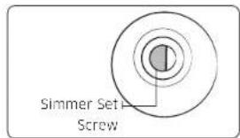
Identify which burner is exhibiting too high or too low simmer flame size, adjust as necessary by following steps below:
-
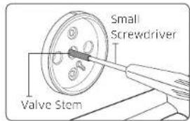
Rotate a knob to Lo position and remove the knob from the valve stem while the flame is lit.
-
Carefully push the screw driver into the stem of the valve, until it hits the simmer set screw. Make sure the screwdriver flathead is seated into the set screw groove.
-
Rotate valve set screw clockwise to decrease Lo setting flame output, or rotate set screw counter clockwise to increase Lo setting flame output.
WARNING
- Do not completely remove the valve set screw from the valve stem. The valve set screw is an integral part of the gas valve assembly. Removing the valve set screw will cause gas to leak.
- After adjusting the valve set screw, inspect the assembly for gas leaks.
30 English
Memo
dacor

DG68-01554A-00
Dacor • Phone: 833-353-5483(USA), 844-509-4659(CANADA) • www.dacor.com
dacor
natural_image
Simple line drawing of a server unit connected to a battery with a symbol (no text or labels)natural_image
Illustration of a kitchen counter with a no-smoking symbol and tools (no text or labels)natural_image
Diagram of a kitchen counter with a prohibition symbol (no text or labels)natural_image
Illustration of a device with a bag and switch inside, showing no text or symbols on the device itself.natural_image
Illustration of a hand opening a cabinet with a prohibition symbol (no text or labels)natural_image
Technical diagram showing a mechanical assembly with an inset close-up of a component (no text or symbols visible)natural_image
Line drawing of a kitchen appliance with front panel and side shelves (no text or symbols)natural_image
Illustration of a person using a computer with a red X mark overlay (no text or symbols)PRECAUCIÓN
natural_image
Pure technical diagram of a mechanical component with no text, numbers, or symbolsnatural_image
Isometric line drawing of a kitchen oven with doors and grilles (no text or symbols)Paso 1. Desembale la estufa.
National Fire Protection Association
Batterymarch Park
Quincy, MA 02269
natural_image
Pure electrical circuit lines without any symbolsnatural_image
Technical line drawing of a device interior showing a vent and socket (no text or symbols)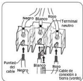
natural_image
Isometric line drawing of an oven with grilles and a side panel (no text or symbols)natural_image
Two identical circular diagrams side by side, one with a gradient fill and the other with concentric rings (no text or symbols)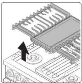
natural_image
Mechanical assembly diagram showing a component with a black arrow pointing to a specific area (no text or symbols present)
natural_image
Isometric line drawing of a kitchen appliance with a tray and side panels (no text or symbols)natural_image
Isometric line drawing of a kitchen appliance with a tray and side panels (no text or symbols)Español 29
natural_image
Illustration of ten identical teardrop-shaped objects arranged in a grid, with no text or symbols present.natural_image
Illustration of a kitchen counter with a no-smoking symbol and tools (no text or labels)natural_image
Illustration of a storefront with a stop sign symbol (no text or labels present)natural_image
Illustration of a window with a prohibition symbol (no text or labels)natural_image
Diagram of a device with a switch and a prohibition symbol (no text or labels)natural_image
Illustration of a hand opening a kitchen appliance with a prohibition symbol (no text or labels)natural_image
Technical diagram showing a mechanical assembly with an inset close-up of a component (no text or symbols visible)natural_image
Line drawing of a kitchen appliance with front panel and side shelves (no text or symbols)natural_image
Illustration of a person using a computer with a red X mark overlay (no text or symbols)ATTENTION
natural_image
Illustration of a person using a tool to adjust or install a furniture cabinet (no text or symbols present)natural_image
Pure technical diagram of a mechanical component with no text, numbers, or symbolsnatural_image
Line drawing of an open kitchen oven with doors and grilles (no text or symbols)National Fire Protection Association
Batterymarch Park
Quincy, MA 02269
natural_image
Pure electrical circuit lines without any symbolsnatural_image
Technical line drawing of a device interior showing internal components and mounting points (no text or symbols)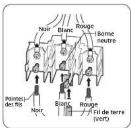
26 Français
natural_image
Isometric line drawing of an oven with grilles and doors (no text or symbols)natural_image
Technical diagram of a mechanical assembly with no visible text or symbolsnatural_image
Technical line drawing of a mechanical or electrical component with no visible text or symbolsnatural_image
Illustration of ten identical teardrop-shaped objects arranged in a grid, with no text or symbols present.- ANTI-TIP DEVICE
- WARNING
- Contents
- Before you begin 4
- Important safety information 4
- Dual fuel range components 10
- Installation requirements 12
- Tools and materials 18
- Installation instructions 19
- Before you begin
- About this manual
- Read these instructions completely and carefully.
- Important note to the installer
- Important note to the consumer
- Important note to the servicer
- Important safety information
- Read all instructions before using this appliance
- Symbols used in this manual
- CAUTION
- NOTE
- California Proposition 65 Warning
- Commonwealth of Massachusetts
- General safety
- Fire safety
- Gas safety
- Checking for gas leaks
- Electrical and grounding safety
- Installation safety
- Location safety
- Cooktop safety
- Oven safety
- Self-cleaning oven safety
- Dual fuel range components
- Installation requirements
- Location requirements
- Clearances and dimensions
- English
- Minimum dimensions
- Installation guide
- To remove safely from the pallet
- To avoid breakage
- Gas requirements
- Provide adequate gas supply
- Special gas requirements (gas models sold in Massachusetts)
- COMMONWEALTH OF MASSACHUSETTS REQUIREMENTS:
- Electrical requirements
- All ranges
- Dual fuel models
- Grounding
- Usage situations where appliance power cord will be disconnected frequently
- Additional installation requirements for mobile homes
- Tools and materials
- What's in the box
- Installation instructions
- Installing your Dual fuel range
- Step 1. Unpack the range
- Step 2. Meeting electrical connection requirements
- Effective January 1, 1996, the National Electrical Code requires that new construction (not existing) utilize a 4-conductor connection to an electric range. When installing an electric range in new construction, follow Steps 2 and 3 for 4-wire connection.
- Step 3. Accessing the power cord connection
- Step 4. Installing the power cord
- Installing a 3-wire power cord
- Installing a 4-wire power cord
- Step 5. Installing the conduit
- Step 6. Replacing the access cover
- Step 7. Connect the range to gas supply
- Flexible connector hookup
- Step 8. Convert to Ip gas (optional)
- Step 9. Install the anti-tip device
- Step 10. Plug in and place
- English
- Step 12. Assemble the surface burners
- Step 13. Check the ignition of surface burners and oven burners
- To turn on a surface burner:
- Checking the flame quality:
- Step 14. Final installation checklist
- To adjust flame low setting
- Memo
- PRECAUCIÓN
- Paso 1. Desembale la estufa.
- ATTENTION
Brand : Dacor
Model : DOP48T963DS
Category : Cooker