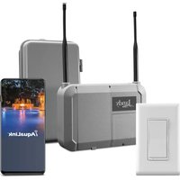
AquaLink TCX - Smart Home Jandy - Free user manual and instructions
Find the device manual for free AquaLink TCX Jandy in PDF.


| Product Type | Pool Automation Power Center |
| Brand | JANDY |
| Model | AquaLink TCX |
| Intended Use | Residential pools, spas, and hot tubs |
| Power Supply | 240/120 VAC, 60/50 Hz, 0.5 A |
| High Voltage Contact Rating | 25 A; 3 HP @ 240 VAC, 1 1/2 HP @ 120 VAC; 1500 W incandescent |
| Low Voltage Contact Rating | Class 2, 1 A @ 24 VAC |
| Main Functions | Control and programming of pumps, heating, lighting, valves, salt chlorinator, and other pool equipment |
| Package Contents | Enclosure (model TCXP), mounting hardware, outdoor temperature sensor, wireless light switch, command center |
| Sensors | Outdoor air temperature sensor (black/red wires on terminals 7 and 8) |
| Connectivity | Low voltage RS-485 communication; compatible with iAquaLink app |
| Compatibility | Single-speed and variable-speed pumps, Jandy valve actuators (JVA), salt chlorinator, lighting |
| Safety Distance (U.S.) | At least 1.5 m (5 ft) from the inner wall of the pool |
| Safety Distance (Canada) | At least 3 m (9.8 ft) from the inner wall of the pool |
| Recommended Mounting Height | At least 61 cm (2 ft) above ground |
| Required Electrical Protection | Ground Fault Circuit Interrupter (GFCI) for submersible lighting |
| Installation | By a qualified professional; comply with national and local electrical codes |
| Materials Provided by Installer | Flexible conduit, high and low voltage cables, circuit breakers, GFCI receptacle or breaker |
| Dimensions (approximate) | Approximately 30 x 30 x 15 cm (typical enclosure) |
| Weight (approximate) | Approximately 2.5 kg |
| Warranty | Manufacturer's express warranty; improper installation voids it |
| Maintenance and Cleaning | Keep dry and protected from water splashes; check connections regularly |
| Safety | Disconnect power before maintenance; equipotential bonding required; risk of electric shock; do not allow children to use without supervision |
| Spare Parts and Repairability | 5 A/125 V fuse; O-rings; contact technical support for other parts |
Frequently Asked Questions - AquaLink TCX Jandy
User questions about AquaLink TCX Jandy
0 question about this device. Answer the ones you know or ask your own.
Ask a new question about this device
Download the instructions for your Smart Home in PDF format for free! Find your manual AquaLink TCX - Jandy and take your electronic device back in hand. On this page are published all the documents necessary for the use of your device. AquaLink TCX by Jandy.
USER MANUAL AquaLink TCX Jandy
natural_image
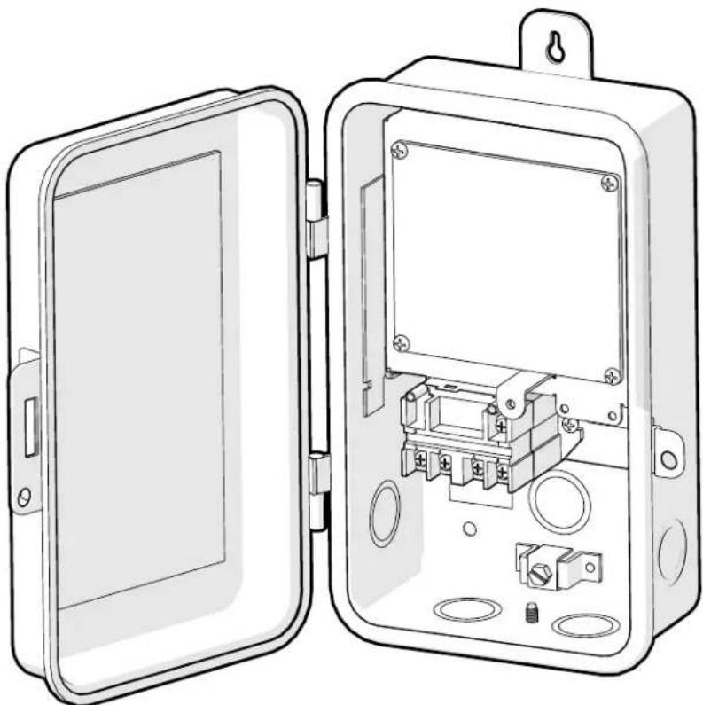
Technical line drawing of an open electrical enclosure with internal components (no text or symbols)AquaLink® TCX™ Power Center
Pool Only
WARNING
FOR YOUR SAFETY - This product must be installed and serviced by a contractor who is licensed and qualified in pool equipment by the jurisdiction in which the product will be installed, where such state or local or provincial requirements exist. In the event no such state or local requirement exists, the individual in charge of installation must be a professional with sufficient experience in pool equipment installation and maintenance, so that all of the instructions in this manual can be followed exactly. Improper installation and/or operation can create dangerous electrical hazards, which can cause high voltages to run through the electrical system. Before installing this product, read and follow all warning notices and instructions that accompany this product. Failure to follow warning notices and instructions may result in property damage, personal injury, or death. Improper installation and/or operation will void the warranty.

If these instructions are not followed exactly, a fire or explosion may result, causing property damage, personal injury, or death.
ATTENTION INSTALLER: This manual contains important information about the installation, operation and safe use of this product. This information should be given to the owner/operator of this equipment.
Table of Contents
Section 1. IMPORTANT SAFETY INSTRUCTIONS .... 3
1.1 Safety Instructions....3
1.2 Pool Pump Suction Entrapment
Prevention Guideline....5
1.3 Required Tools and Equipment......6
1.4 Materials Supplied by the Installer ..... 7
1.5 Specifications....7
Section 2. System Overview ...... 7
2.1 Package Contents....7
2.2 Location Requirements 7
Section 3. AquaLink TCX Power Center Installation .... 7
3.1 Mounting 7
3.2 Wiring 8
3.3 Installing the Air Temperature Sensor ..11
3.4 Installing and Wiring the Command Hub ....11
3.5 Installing Wireless Light Switch.....11
3.6 Bonding....11
Section 4. AquaLink TCX™ Retro Fit Installation ....11
4.1 Wiring....11
4.2 Installing the Air Temperature Sensor .. 14
4.3 Installing and Wiring the Command Hub 14
4.4 Installing Wireless Light Switch.....14
4.5 Bonding 14
Section 1. IMPORTANT SAFETY INSTRUCTIONS
READ AND FOLLOW ALL INSTRUCTIONS
1.1 Safety Instructions
All electrical work must be performed by a licensed electrician and conform to all national, state, provincial and local codes. When installing and using this electrical equipment, basic safety precautions should always be followed, including the following:
WARNING
EQUIPMENT UNDER PRESSURE: Always turn pump off prior to installation or service. Your pump/filter system is operated under pressure and the pressure must be released before you begin work. Please see your pump/filter owner's manual for further instructions.
WARNING
To reduce the risk of electric shock, fire or injury, service should only be attempted by a qualified pool service professional.
Risk of electric shock: Install the power center at least five (5) feet (1.52 m) from the inside wall of the pool and/or hot tub using non-metallic plumbing. Canadian installations must be at least three (3) meters from the water.
WARNING
Risk of electric shock which can result in serious injury or death: Before attempting to install or service, ensure that all power to the circuit supplying power to the system is disconnected or turned off at the circuit breaker. All wiring must be done in accordance with the National Electrical Code ^® (NEC) ^® , NFPA-70 ^® , including those in Article 680 - Swimming Pools, Fountains, and Similar Installations.
In Canada, the Canadian Electrical Code (CEC), CSA C22.1, must be followed. All applicable local installation codes and regulations must be followed.
ATTENTION: This power center and the chlorine generator control center are not to be considered as suitable for use as service equipment. Therefore, it is required to have the appropriate means of disconnection, circuit isolation, and/or branch circuit protection installed upstream of the power/control center
WARNING
To reduce the risk of injury do not permit children to use this product unless they are closely supervised at all times
WARNING
Risk of Accidental Drowning. Extreme caution must be exercised to prevent unauthorized access by children. To avoid accidents, ensure that children cannot use a spa or hot tub unless they are closely supervised at all times
This appliance is not intended for use by persons (including children) with reduced physical, sensory or mental capabilities, or lack of experience and knowledge, unless they have been given supervision or instruction concerning use of the appliance by a person responsible for their safety.
PREVENT CHILD DROWNING: Do not let anyone, especially small children, sit, step, lean or climb on any equipment installed as part of your pool's operational system. Locate the components of your operational system at least 1 m (3 ft 3 in) from the pool so children cannot use the equipment to access the pool and be injured or drown.
To reduce the risk of injury, do not remove the suction fittings of your spa or hot tub. Never operate a spa or hot tub if the suction fittings are broken or missing. Never replace a suction fitting with one rated less than the flow rate marked on the equipment assembly.
WARNING
To avoid injury ensure that you use this control system to control only packaged pool/spa heaters which have built-in operating and high limit controls to limit water temperature for pool/spa applications. This device should not be relied upon as a safety limit control. Water temperature in excess of 100^ F ( 38^ C) may be hazardous to your health.
WARNING
A terminal bar marked "GROUND" is provided within the power center. To reduce the risk of electrical shock, connect this terminal bar to the grounding terminal of your electric service or supply panel with a continuous copper conductor having green insulation and one that is equivalent in size to the circuit conductors supplying this equipment, but no smaller than no. 12 AWG (3.3 mm2). In addition, a second wire connector should be bonded with a no. 8 AWG (8.4 mm2) copper wire to any metal ladders, water pipes, or other metal within five (5) feet (1.52 m) of the pool/spa. In Canada, the bonding wire must be minimum 6 AWG (13,3 mm2).
WARNING
A ground-fault circuit-interrupter must be provided if this device is used to control underwater lighting fixtures. The conductors on the load side of the ground-fault circuit-interrupter shall not occupy conduit, boxes, or enclosures containing other conductors unless the additional conductors are also protected by a ground-fault circuit-interrupter. Refer to local codes for complete details.
CAUTION: This device is intended for use with permanent swimming pools and may also be used with hot tubs and spas if so marked. Do not use with storable pools. A permanently-installed pool is constructed in or on the ground or in a building such that it cannot be readily disassembled for storage. A storable pool is constructed so that it is capable of being readily disassembled for storage and reassembled to its original integrity.
When mixing acid or other chemicals with water, ALWAYS ADD THE ACID OR CHEMICALS TO WATER. NEVER ADD WATER TO THE ACID OR CHEMICALS.
CAUTION: It is important to note that certain materials used in and around swimming pools and spas may not be compatible with chemicals commonly used to purify pool and spa water (e.g. acids, chlorine, salt, stabilizers, etc.).
Zodiac Pool Systems LLC does not warrant or guarantee that the chlorinated water generated by the Jandy Pro Series chlorine generating device will not damage or destroy certain types of plants, decking, coping and other materials in and around your pool and/or spa. Before selecting materials to be used in and around your pool and/or spa, please discuss all options with your contractor to assess the compatibility of such materials and chemicals.
Some helpful considerations may include:
- Choosing plants that can withstand splash out of pool water containing chlorine and/or salt and other water purification chemicals.
- All metal components used in and around a pool should be of a high grade, quality stainless steel.
- Careful selection of masonry products. The porosity and hardness of natural stones varies greatly. Therefore we recommend you consult with your builder or stone contractor on the best choice for stone materials around your pool or spa.
- Sealing all masonry products. Professionals in the stone industry specify that even natural stone, especially when used outdoors, be sealed to prevent weathering, staining, and premature degradation. Consult with your stone or deck contractor for the proper sealer for the masonry products you have selected to use around your pool or spa.
- For optimal results, sealers should be reapplied on a regular basis. Reapply the protective sealer on a schedule per the manufacturer's instructions.
- Use of chemicals other than those recommended may be hazardous. Follow the chemical manufacturers instructions.
WARNING
Prolonged immersion in hot water may induce hyperthermia. Hyperthermia occurs when the internal temperature of the body reaches a level several degrees above the normal body temperature of 37 °C (98.6 °F). The symptoms of hyperthermia include dizziness, fainting, drowsiness, lethargy, and an increase in the internal temperature of the body. The effects of hyperthermia include:
• Unawareness of impending danger
- Failure to perceive heat
- Failure to recognize the need to exit spa
• Physical inability to exit spa
• Fetal damage in pregnant women
- Unconsciousness resulting in a danger of drowning
To Reduce the Risk of Injury:
- The water in a spa should never exceed 40°C (104°F). Water temperatures between 38°C (100°F) and 40°C (104°F) are considered safe for a healthy adult. Lower water temperatures are recommended for young children and when spa use exceeds 10 minutes.
- Since excessive water temperatures have a high potential for causing fetal damage during the early months of pregnancy, pregnant or possibly pregnant women should limit spa water temperatures to 38°C (100°F).
- Before entering a spa or hot tub, the user should measure the water temperature with an accurate thermometer since the tolerance of water temperature-regulating devices varies.
- The use of alcohol, drugs, or medication before or during spa or hot tub use may lead to unconsciousness with the possibility of drowning.
- Obese persons and persons with a history of heart disease, low or high blood pressure, circulatory system problems, or diabetes should consult a physician before using a spa.
- Persons using medication should consult a physician before using a spa or hot tub since some medication may induce drowsiness while other medication may affect heart rate, blood pressure, and circulation.
• People with infectious diseases should not use a spa or hot tub.
- To avoid injury, exercise care when entering or exiting the spa or hot tub.
- Do not use drugs or alcohol before or during the use of a spa or hot tub to avoid unconsciousness and possible drowning.
- Pregnant or possibly pregnant women should consult a physician before using a spa or hot tub.
- Water temperature in excess of 38°C (100°F) may be injurious to your health.
- Before entering a spa or hot tub measure the water temperature with an accurate thermometer.
- Do not use a spa or hot tub immediately following strenuous exercise.
- Prolonged immersion in a spa or hot tub may be injurious to your health.
- Do not permit any electric appliance (such as a light, telephone, radio, or television) within 1.5 m (5 ft.) of a spa or hot tub.
- The use of alcohol, drugs or medication can greatly increase the risk of fatal hyperthermia in hot tubs and spas.
WARNING
Improper gas heater installation or maintenance can cause nausea or asphyxiation from carbon monoxide in flue gases which could result in severe injury, or death. For indoor installations, as an additional measure of safety, Zodiac Pool Systems LLC strongly recommends installation of suitable Carbon Monoxide detectors in the vicinity of this appliance and in any adjacent occupied spaces.
WARNING
Jandy Pro Series chlorine generating devices are designed for domestic (residential) swimming pool use only. Contrary use could affect performance, void warranty, and may result in property damage, serious injury, or death.
- Operating a chlorine generator without water flowing through the cell may cause a build up of flammable gases, resulting in fire or explosion.
- Keep equipment out of reach of children.
- A damaged supply cord should only be replaced by the manufacturer, service agent or electrician.
- When installing and using this electrical equipment, always follow basic safety precautions.
- Before performing installation, disconnect all power.
- Connect to a circuit that is protected by a ground-fault circuit interrupter (GFCI).
- Do not install within an outer enclosure or beneath the skirt of a hot tub or spa.
ATTENTION: This device complies with part 15 of the FCC Rules. Operation is subject to the following two conditions: (1) This device may not cause harmful interference, and (2) this device must accept any interference received, including interference that may cause undesired operation.
NOTE: This equipment has been tested and found to comply with the limits for a Class B digital device, pursuant to part 15 of the FCC Rules. These limits are designed to provide reasonable protection against harmful interference in a residential installation. This equipment generates, uses and can radiate radio frequency energy and, if not installed and used in accordance with the instructions, may cause harmful interference to radio communications. However, there is no guarantee that interference will not occur in a particular installation. If this equipment does cause harmful interference to radio or television reception, which can be determined by turning the equipment off and on, the user is encouraged to try to correct the interference by one or more of the following measures:
- Reorient or relocate the receiving antenna.
- Increase the separation between the equipment and receiver.
- Connect the equipment to an electrical source on a circuit different from that to which the receiver is connected.
- Consult the dealer or an experienced radio/TV technician for help.
Modifications made to this equipment, which are not authorized by the manufacturer, may void the user's authority to operate this equipment.
1.2 Pool Pump Suction Entrapment Prevention Guideline

WARNING
Pump suction is hazardous and can trap and drown or disembowel bathers. Do not use or operate swimming pools, spa, or hot tubs if a suction outlet cover missing, broken, or loose: The following guidelines provide information for pump installation that minimizes the risk of injury to users of pools, spas, and hot tubs:
Entrapment Protection: The pump suction system must provide protection against the hazards of suction entrapment.
Suction Outlet Covers: All suction outlets must have correctly installed, screw-fastened covers in place. All suction outlet (drain) covers must be maintained. Drain covers must be listed/certified to the latest version of ANSI®/ASME® A112.19.8 or its successor standard, ANSI/APSP-16. They must be replaced if cracked, broken, or missing.
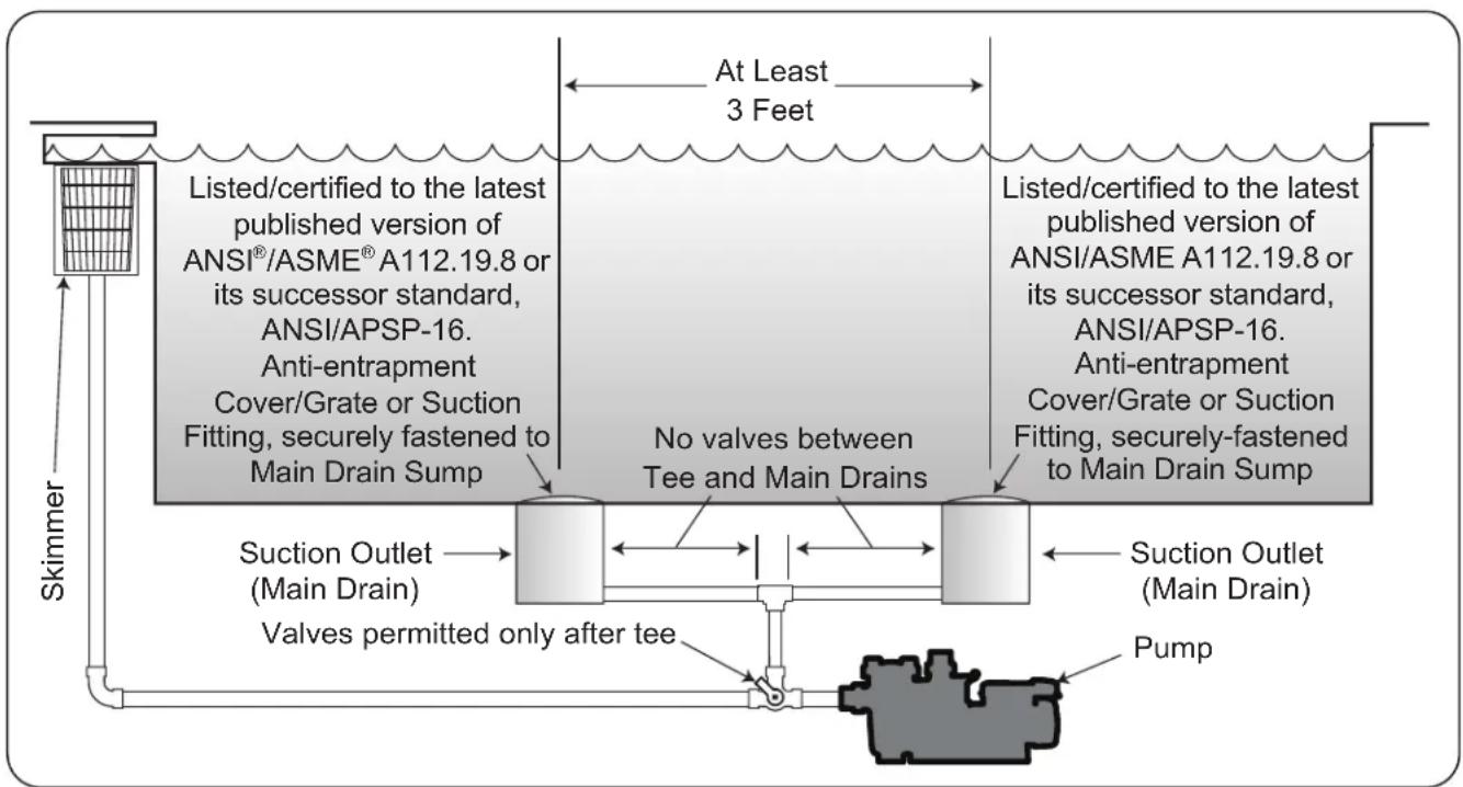
Number of Suction Outlets Per Pump: Provide at least two (2) hydraulically-balanced main drains, with covers, as suction outlets for each circulating pump suction line. The centers of the main drains (suction outlets) on any one (1) suction line must be at least three (3) feet apart, center to center. See Figure 1.
The system must be built to include at least two (2) suction outlets (drains) connected to the pump whenever the pump is running. However, if two (2) main drains run into a single suction line, the single suction line may be equipped with a valve that will shut off both main drains from the pump. The system shall be constructed such that it shall not allow for separate or independent shutoff or isolation of each drain. See Figure 1.
More than one (1) pump can be connected to a single suction line as long as the requirements above are met.
Water Velocity: The maximum water velocity through the suction fitting or cover for any suction outlet must be 1.5 feet per second unless the outlet complies with the latest version of ANSI/ASME A112.19.8 or its successor standard, ANSI/APSP-16, the standard for Suction Fittings For Use in Swimming Pools, Wading Pools, Spas, and Hot Tubs. In any case, do not exceed the suction fitting's maximum designed flow rate.
If 100% of the pump's flow comes from the main drain system, the maximum water velocity in the pump suction hydraulic system must be six (6) feet per second or less, even if one (1) main drain (suction outlet) is completely blocked. The flow through the remaining main drain(s) must comply with the latest version of ANSI/ASME A112.19.8 or its successor standard, ANSI/APSP-16, the standard for Suction Fittings For Use in Swimming Pools, Wading Pools, Spas, and Hot Tubs.
Testing and Certification: Suction outlet covers must have been tested by a nationally recognized testing laboratory and found to comply with the latest version of ANSI/ASME A112.19.8 or its successor standard, ANSI/APSP-16, the standard for Suction Fittings For Use in Swimming Pools, Wading Pools, Spas, and Hot Tubs.
Fittings: Fittings restrict flow; for best efficiency use fewest possible fittings (but at least two (2) suction outlets).
Avoid fittings which could cause an air trap.
Pool cleaner suction fittings must conform to applicable International Association of Plumbing and Mechanical Officials (IAPMO ^® ) standards.
flowchart
graph TD
    A["Skimmer"] --> B["Listed/certified to the latest published version of ANSI®/ASME® A112.19.8 or its successor standard, ANSI/APSP-16. Anti-entrapment Cover/Grate or Suction Fitting, securely fastened to Main Drain Sump"]
    B --> C["Listed/certified to the latest published version of ANSI/ASME A112.19.8 or its successor standard, ANSI/APSP-16. Anti-entrapment Cover/Grate or Suction Fitting, securely fastened to Main Drain Sump"]
    C --> D["Suction Outlet (Main Drain)"]
    D --> E["Valves permitted only after tee"]
    E --> F["Pump"]
    F --> G["Suction Outlet (Main Drain)"]
    G --> H["No valves between Tee and Main Drains"]
    H --> I["At Least 3 Feet"]
    I --> J["At Least 3 Feet"]
Figure 1. Number of Suction Outlets Per Pump
SAVE THESE INSTRUCTIONS

ZODIAC®
ZODIAC
FAMILY OF BRANDS | Heritage of Excellence
Quality Promise
As industry leaders committed to giving you the perfect pool experience, we-
Promise to maintain the highest quality standards in all areas of operation.
Promise to use high quality materials and world-class processes to manufacture our products.
Promise that your equipment will arrive completely tested in pool environments, inspected and quality-assured for reliability and durability.
We stand by our promise.
Our promise is backed by dedicated support and our written express product warranty.
For technical assistance please call 1-800-822-7933
What you say matters. Tell us what you think by calling 1-760-734-8844 or email feedback@zodiac.com for questions or input.

Jandy
Polaris
ZODIAC
1.3 Required Tools and Equipment
Please ensure that the following list of tools and equipment are available to the installer at the time of install


Smart Device with iAquaLink App
Drill/Impact Driver
Safety Eyewear Gloves Screwdrivers*



Combination/ Diagonal Pliers**
Tape Measure Voltage Meter Hammer 1/4" Hex Driver
1.4 Materials Supplied by the Installer
- Flexible Conduit
- Conduit Connectors
• Wire High Voltage #12 AWG Minimum
• Wire Low Voltage - 4 conductor
Min. #22 AWG Communication Cable
(Insulation Colors: Red, Black, Yellow, Green)
• Wire Connectors (wire nuts)
• High Voltage Breakers
• GFCI Receptacle or GFCI Breaker
1.5 Specifications
| Power Supply | ||
| USA | 240/120VAC; 60/50 Hz; 0.5 A | |
| CAN | 240/120VAC; 60/50 Hz; 0.5 A | |
| Contact Rating | ||
| USA | High Voltage | 25 A; 3HP @ 240VAC1 1/2 HP @ 120VAC1500 Watts Incandescent |
| Low Voltage Class 2, 1 A @ 24VAC | ||
| CAN | High Voltage | 25 A; 3HP @ 240VAC1 1/2 HP @ 120VAC1500 Watts Incandescent |
| Low Voltage Class 2, 1 A @ 24VAC | ||

WARNING
The AquaLink TCX power center should not be considered suitable for use as service equipment. Therefore, it is required to have the appropriate means of disconnection, circuit isolation, and/or branch circuit protection installed upstream of the power center.
Section 2. System Overview
This manual provides installation and basic operational instructions for the Jandy AquaLink TCX power center. The AquaLink TCX is an integrated automation system capable of controlling and scheduling a wide array of equipment for residential pools.
Read the installation and operation instructions completely before proceeding with the installation. Keep this manual in a safe place for future reference when inspecting or servicing the power center.
Before starting, check that you have the correct parts as indicated below. If any parts are missing or incorrect, please call your local distributor or technical support at 1-800-822-7933 for assistance.
2.1 Package Contents
Package contents will vary depending on which AquaLink TCX configuration you are installing.
| AquaLink TCX Pool Only W/Automation |
| Enclosure* and PIB |
| Mounting HardwareScrew #8-15 X 1 1/4” (Qty 3)Wall Anchor #8 1” (Qty 3) |
| Screw And Fuse Goody BagFuse 5A/125VO-Ring 5/32” IDScrew #8-32 X 3/8” |
| Wire Cover Tube Kit24” TubingBushing 20.4mmBonding LugScrew #10-24 X 5/8”Nut 10-24 |
| Air Temperautre Sensor |
| Wireless Light Switch/Wallplate |
| Command Hub |
| *Note: Enclosure only included on TCXP model. Conversion Kit model does not include enclosure. |
2.2 Location Requirements
In order to protect the AquaLink TCX power center from pressurized water spray (such as that from irrigation sprinklers) and from mechanical impacts and/or damage, it should be located:
• Near the primary equipment pad.
- At least 2^ (61 cm) above the ground.
- At least 5' (1.5 ~m) away from the inside edge of the pool or spa in the US.
- At least 3 m (9.8') away from the inside edge of the pool or spa in Canada.
Section 3. AquaLink TCX Power Center Installation
3.1 Mounting
The AquaLink TCX power center is shipped with mounting brackets fastened on the back.
- Turn the power center over and inspect the brackets installed on the back.
-
If any parts are missing or damaged, please call your local distributor or technical support at 1-800-822-7933 for assistance.
-
Measure Distance From Breaker (refer to Location Requirements and your equipment manual).
- Measure Distance To Equipment (refer to Location Requirements and your equipment manual).
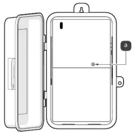
- Open up the AquaLink TCX enclosure and remove the metal dead front. The dead front is held in place by one screw, see Figure 1 (a).
natural_image
Diagram of a door panel with open lid and internal compartments, showing no text or symbolsFigure 1. Remove Dead Front Screw
- Mark the location for the mounting screws. One is located on top of the enclosure and two are located inside the enclosure towards the bottom.
- Drill holes where the mounting screws will be installed.
- Secure screws (or other hardware appropriate for the mounting surface) through the mounting holes of the AquaLink TCX enclosure.
3.2 Wiring

WARNING
Risk of electric shock which can result in serious injury or death: Before attempting to install or service, ensure that all power to the circuit supplying power to the system is disconnected or turned off at the circuit breaker. All wiring must be done in accordance with the National Electrical Code ^® (NEC(R)) ^® , NFPA70 ^® .
In Canada, the Canadian Electrical Code (CEC), CSA C22.1, must be followed. All applicable local installation codes and regulations must be followed.
Wiring connections must be made exactly as shown in the wiring diagram found on the inside of the power center door panel. The NEC and CEC also require that the equipment and/or appliances associated with the pool water circulating system, including, but not limited to, pump motors and
heaters, be bonded together as part of the equipotential bonding grid. Zodiac Pool Systems LLC provides a labeled bonding lug on the bottom of the power center to accommodate this requirement.
3.2.1 High Voltage Wiring (Single Speed Pumps)
NOTE: For single speed pumps the filter pump breaker will be used to power TCX. Relay cannot be configured for use with other equipment due to being in use for the pump.
- Turn off power at the breaker panel.
- Remove two of the knockouts from the enclosure. One knockout will lead to the breaker panel and the other will lead to the pool equipment.
-
Thread a 1/2" MPT terminal adapter into the knockouts on the enclosure.
-
Cut and run conduit. Measure the distance from the filter pump breaker to the enclosure.
-
Cut a piece of 1/2" electrical conduit to match the distance from the filter pump breaker to the enclosure..
-
Feed cables from the filter pump breaker through the conduit and into the AquaLink TCX enclosure.
-
Press the conduit into the terminal adapter.
-
Locate the two input power cables that come from the filter pump breaker.
-
Connect one 'Line' input to Terminal 1 and the other to Terminal 3, see Figure 2 (a).
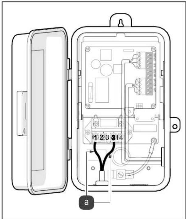
Figure 2. Connect Input Cables
- Connect single speed filter pump to load side of relay, use terminals 2 and 4, see Figure 3 (a).
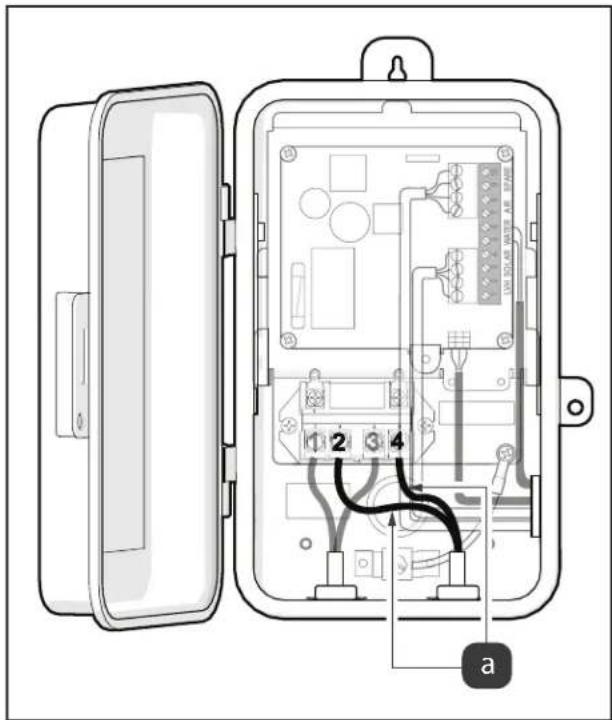
Figure 3. Connect Load Input Cables
3.2.2 High Voltage Wiring (Variable Speed Pumps)
NOTE: The variable speed pump must be wired "hot".
- Turn off power at the breaker panel.
- Remove two of the knockouts from the enclosure. One knockout will lead to the breaker panel and the other will lead to the pool equipment.
- If relay is not to be used for a Saltwater Chlorinator, connect Equipment (Lighting/Water Feature Pump/Booster Pump/Solar Pump). Measure the distance from the equipment to the enclosure.
- If relay will be used for Saltwater Chlorinator, pull lines from Filter Pump breaker to line side of relay and wire pump on line side of the relay. Wire the Saltwater Chlorinator to load side.
- Cut a piece of 1/2" electrical conduit to match this distance.
- Feed the cables from the equipment through the conduit and into the AquaLink TCX enclosure.
- Press the conduit into the terminal adapter.
- Connect the ground wire to the green screw located on the AquaLink TCX chassis. The ground wire will be green/yellow.
- Connect one "Load" input to Terminal 2 and the other to Terminal 4, see Figure 4 (a).
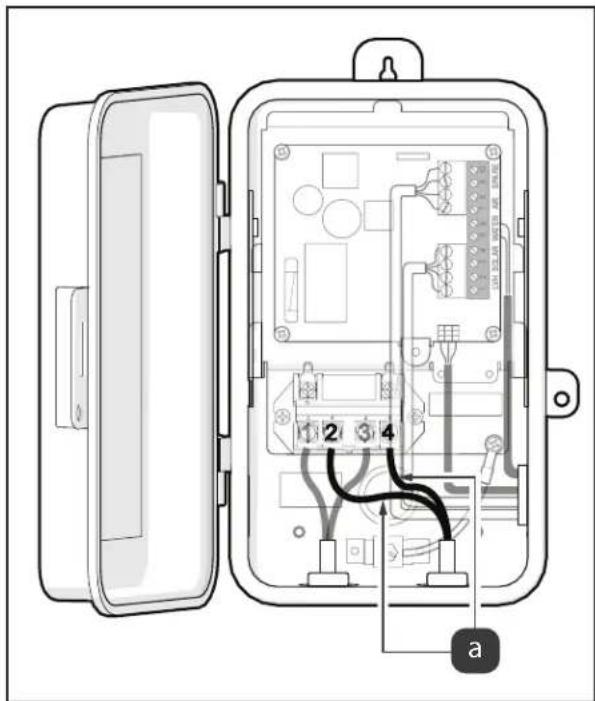
Figure 4. Connect Load Input Cables
3.3.2 Low Voltage Wiring
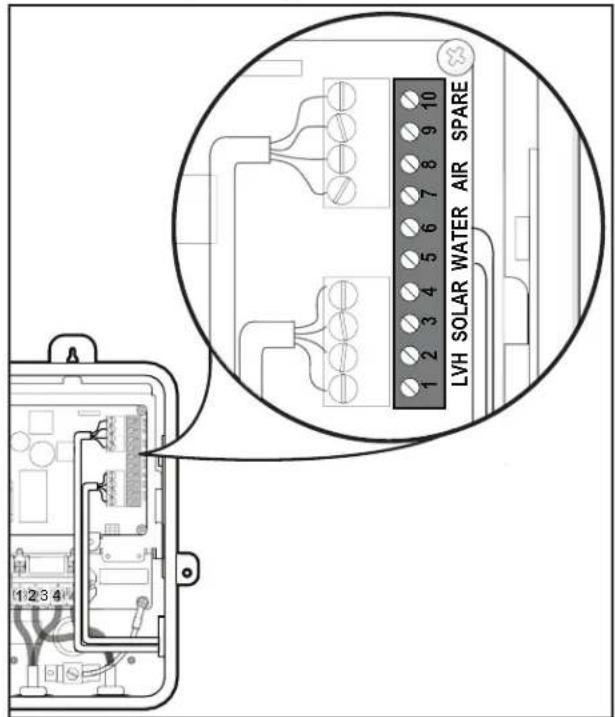
Figure 5. Green 10 Pin Connector Close Up
NOTE: Permanently separate high and low voltage wiring by using corrugated tubing.
- Connect the low voltage RS-485 communication wires.
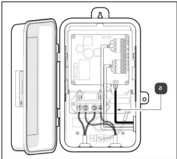
- If JVA is present, thread JVA connector through the lower right corner of the board, through the side knockout and strain relief fitting.
- Connect JVA cable, see Figure 6 (a).
natural_image
Interior view of an electrical enclosure showing internal components and wiring (no text or labels)Figure 6. Pool Only Version, Connect Line Inputs & JVA Cable
- Install Low Voltage Wires. Install the wires for the temperature sensor connections through the side knockout, see Figure 7 (a).
- Connect wires in the order listed on the board.
- Check all connection points and wiring for secure connections.
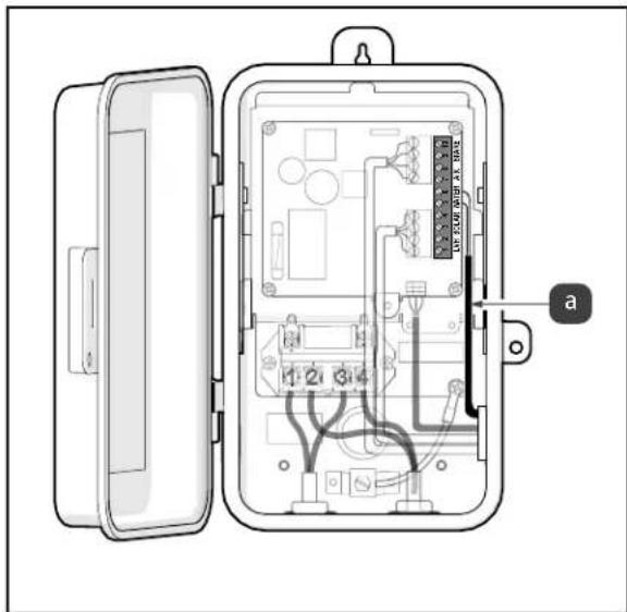
natural_image
Interior view of an electrical meter box showing internal circuitry and wiring (no text or labels visible)Figure 7. Connect Low Voltage Wires
- If bottom half of dead panel needs to be removed use some diagonal pliers to cut the two rear tabs, see Figure 8 (a).
- Cut dead panel label across dead panel opening, see Figure 8 (b).
- Swing dead panel bottom back and forth until front tabs break off, see Figure 8 (c).
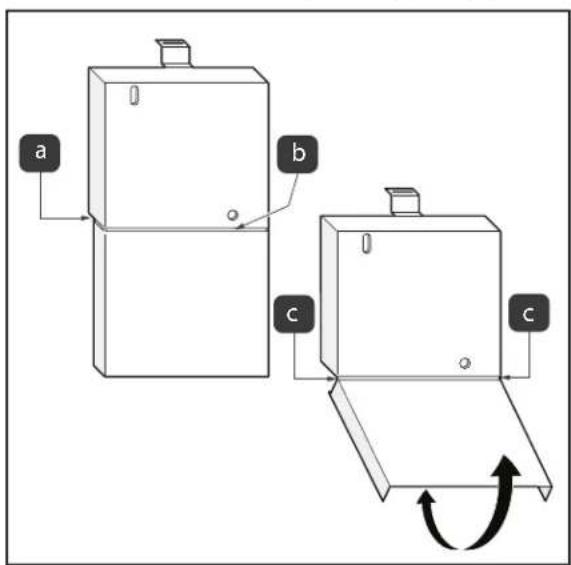
Figure 8. Reinstall Dead Front
- Reinstall the dead front panel with the screw provided
- Close the enclosure door.
- Turn on the breaker to restore power.
3.3 Installing the Air Temperature Sensor
NOTE: DO NOT place the sensor in direct sunlight.
- Install the Air Temperature Sensor in a convenient location exposed to outdoor temperatures.
- Run the sensor wire to the Aqualink TCX power center through the low voltage raceway (See wiring diagram on Power Center door).
NOTE: Determine the length the sensor wire needs to be. Cut the end of the wire off, DO NOT splice this wire.
- Remove the green 10-pin terminal bar from the Power Center Board.
- Place the BLACK wire in terminal #7 and the RED wire in terminal #8.
- Replace the green 10-pin terminal bar on the Power Center Board.
- Turn on the breaker to restore power.
3.4 Installing and Wiring the Command Hub
- See Command Hub Installation Manual for detailed instructions.
3.5 Installing Wireless Light Switch
- Follow the app and the included instructions to pair your wireless light switch.
- Compatible with Jandy part number WLS4INF
3.6 Bonding
Zodiac Pool Systems LLC, requires that the AquaLink TCX power center be connected to a “bonding loop” that includes all electrical equipment in the system and on the equipment pad. Bonding lugs must be connected with a solid copper wire not smaller than 8 AWG (6 AWG in Canada). Failure to do so may void the Zodiac Pool Systems LLC warranty.
CAUTION
To prevent premature failure of the equipment resulting from stray voltages and voltage differentials, the AquaLink TCX power center must be bonded to other equipment which is part of the pool plumbing system with a solid copper wire not smaller in diameter than 8 AWG (6 AWG in Canada).
Additionally, in the United States the National Electrical Code ^® (NEC ^® ) and in Canada the Canadian Electrical Code (CEC), require that all metallic components of a pool structure, including reinforcing steel, metal fittings and above ground components be bonded together (forming an equipotential bonding grid) with a solid copper conductor not smaller than an 8 AWG (6 AWG in Canada).
The NEC and CEC also require that the equipment and/or appliances associated with the pool water circulating system, including, but not limited to, pump motors and heaters, be bonded together as part of the equipotential bonding grid. Zodiac Pool Systems LLC provides special labeled bonding lugs on the bottom of the power center to accommodate this requirement.
After bonding the electronics to the grounding lug, installer must verify ground continuity using a multimeter.
Bonding lug is provided with kit and should be installed no higher than 2 inches from the bottom of the enclosure. Use a 1/8" drill bit to install hardware.
Section 4. AquaLink TCX™ Retro Fit Installation
4.1 Wiring
The AquaLink TCX chassis and PIB has been designed to easily install into the Intermatic® T104R and T30004R metal enclosures.
- Installer must ensure that the Intermatic ^ enclosure is in acceptable working condition; including all seals/gaskets must be in place and functional; door/hinges/locks must be functional; grounding lug must be present, functional, and bonded; and corrosion must not compromise ingress protection against weather. Otherwise a new enclosure must be used.
WARNING
Risk of electric shock which can result in serious injury or loss of life: Before attempting to install or service, ensure that all power to the circuit supplying power to the system is disconnected or turned off at the circuit breaker. All wiring must be done in accordance with the National Electrical Code® (NEC)®, NFPA-70®.
In Canada, the Canadian Electrical Code (CEC), CSA C22.1, must be followed. All applicable local installation codes and regulations must be followed.
Wiring connections must be made exactly as shown in the wiring diagram found on the inside of the power center door panel. The NEC and CEC also require that the equipment and/or appliances associated with the pool water circulating system, including, but not limited to, pump motors and heaters, be bonded together as part of the equipotential bonding grid. Zodiac Pool Systems LLC. provides a labeled bonding lug on the bottom of the power center to accommodate this requirement.
- Turn power off at breaker panel.
- Disconnect high voltage wiring.
- Remove time clock by pressing mounting tab down and pulling out the clock assembly, see Figure 9 (a)
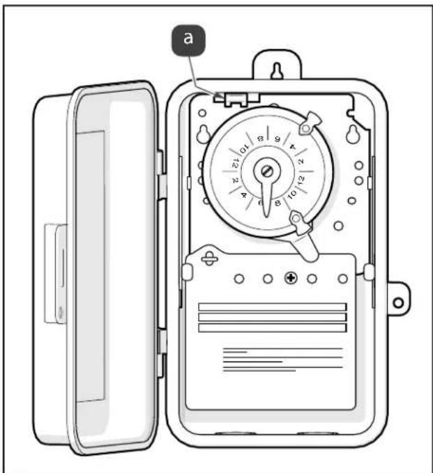
Figure 9. Remove Time Clock from Intermatic ^® Unit
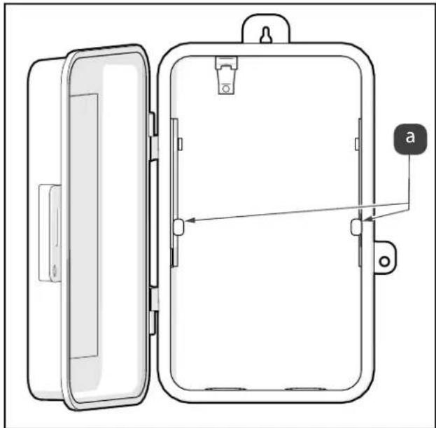
- Lower AquaLink TCX chassis into empty Intermatic® box, slide under retainer ears, see Figure 10 (a)
natural_image
Technical line drawing of a rectangular enclosure with open lid and internal components, no text or symbols presentFigure 10. Intermatic® Retaining Ears Location
- Push AquaLink TCX chassis until it locks into place under the mounting tab see Figure 11 (a)
- Connect the ground wire to the green screw located on the AquaLink TCX mechanism see Figure 11 (b).
- Install bonding lug if one doesn't already exist. (See section 4.3)
- If there is no spring clip, secure TCX chassis with retention screw, see Figure 11 (c).
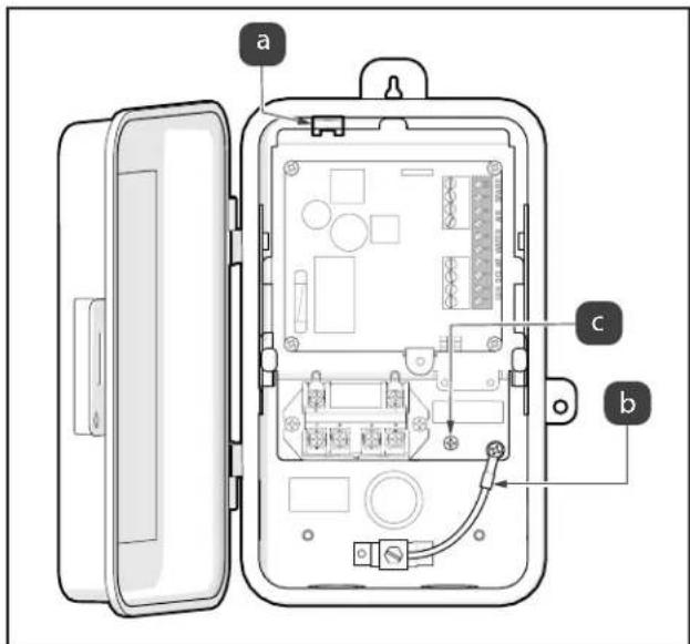
Figure 11. Mounting and Grounding TCX Chassis
4.1.1 Low Voltage Wiring
NOTE: Permanently separate high and low voltage wiring by using corrugated tubing.
- Connect the low voltage RS-485 communication wires.
- Locate the two input power cables that come from the breaker, see Figure 12 (a).
- Connect one 'Line' input to Terminal 1 and the other to Terminal 3, see Figure 12 (b).
- If JVA is present, thread JVA connector through the lower right corner of the board, through the side knockout and strain relief fitting.
- Connect JVA cable, see Figure 12 (c).
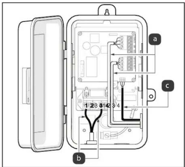
Figure 12. Pool Only Version, Connect Line Inputs & JVA Cable
- Install Low Voltage Wires. Install the wires for the temperature sensor connections through the side knockout, see Figure 13 (a).
- Connect wires in the order listed on the board.
- Connect Equipment (Lighting/Salt/Pump). Measure the distance from the equipment to the enclosure.
- Cut a piece of 1/2" electrical conduit to match this distance.
- Feed the cables from the equipment through the conduit and into the AquaLink TCX enclosure.
-
Press the conduit into the terminal adapter.
-
Connect the ground wire to the green screw located on the AquaLink TCX chassis. The ground wire will be green/yellow.
- Locate the two input cables that come from the equipment.
- Connect one "Load" input to Terminal 2 and the other to Terminal 4, see Figure 13 (b).
- Check all connection points and wiring for secure connections.
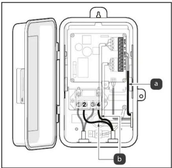
Figure 13. Connect Load Input Cables
- If bottom half of dead panel needs to be removed use some diagonal pliers to cut the two rear tabs, see Figure 14 (a).
- Cut dead panel label across dead panel opening, see Figure 14 (b).
- Swing dead panel bottom back and forth until front tabs break off, see Figure 14 (c).
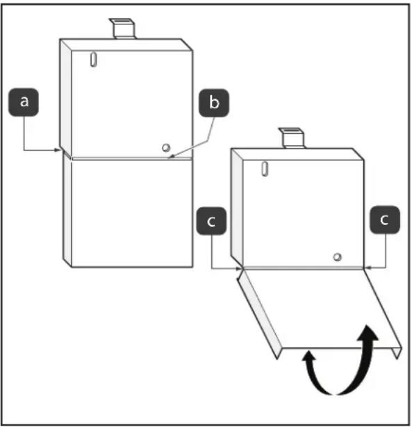
Figure 14. Reinstall Dead Front
- Install the dead front panel with the screw provided.
- Close the enclosure door.
- Turn on the breaker to restore power.
4.2 Installing the Air Temperature Sensor
NOTE: DO NOT place the sensor in direct sunlight.
- Install the Air Temperature Sensor in a convenient location exposed to outdoor temperatures.
- Run the sensor wire to the Aqualink TCX power center through the low voltage raceway (See wiring diagram on Power Center door).
NOTE: Determine the length the sensor wire needs to be. Cut the end of the wire off, DO NOT splice this wire.
- Remove the green 10-pin terminal bar from the Power Center Board.
- Place the BLACK wire in terminal #7 and the RED wire in terminal #8.
- Replace the green 10-pin terminal bar on the Power Center Board.
- Turn on the breaker to restore power.
4.3 Installing and Wiring the Command Hub
• See Command Hub Installation Manual for detailed instructions.
4.4 Installing Wireless Light Switch
- Follow the app and the included instructions to pair your wireless light switch.
- Compatible with Jandy part number WLS4INF
4.5 Bonding
Zodiac Pool Systems LLC., requires that the AquaLink TCX power center be connected to a “bonding loop” that includes all electrical equipment in the system and on the equipment pad. Bonding lugs must be connected with a solid copper wire not smaller than 8 AWG (6 AWG in Canada). Failure to do so may void the Zodiac Pool Systems LLC warranty.
CAUTION
To prevent premature failure of the equipment resulting from stray voltages and voltage differentials, the AquaLink TCX power center must be bonded to other equipment which is part of the pool plumbing system with a solid copper wire not smaller in diameter than 8 AWG (6 AWG in Canada).
Additionally, in the United States the National Electrical Code® (NEC®) and in Canada the Canadian Electrical Code (CEC), require that all metallic components of a pool structure, including reinforcing steel, metal fittings and above ground components be bonded together (forming an equipotential bonding grid) with a solid copper conductor not smaller than an 8 AWG (6 AWG in Canada).
The NEC and CEC also require that the equipment and/or appliances associated with the pool water circulating system, including, but not limited to, pump motors and heaters, be bonded together as part of the equipotential bonding grid. Zodiac Pool Systems LLC provides special labeled bonding lugs on the bottom of the power center to accommodate this requirement.
After bonding the electronics to the grounding lug, installer must verify ground continuity using a multimeter.
Bonding lug is provided with kit and should be installed no higher than 2 inches from the bottom of the enclosure. Use a 1/8" drill bit to intall hardware.
NOTES
Zodiac Pool Systems LLC
2882 Whiptail Loop # 100, Carlsbad CA 92010
1.800.822.7933 | Jandy.com
Zodiac Pool Systems Canada, Inc
3365 Mainway, Unit 2
Burlington, Ontario L7M 1A6
1-888-647-4004 | Jandy.ca
ZODIAC ^® is a registered trademark of Zodiac International, S.A.S.U., used under license. All other trademarks referenced herein are the property of their respective owners.
©2020 Zodiac Pool Systems LLC H0666500_REVE
natural_image
Technical line drawing of an open industrial enclosure with internal components (no text or symbols)FAMILY OF BRANDS | Heritage of Excellence
Promesse de qualité
natural_image
Diagram of a door panel with open lid and internal structure, showing no text or symbolsFigure 1. Retirez la vis de la face neutre
natural_image
Interior view of an electrical enclosure showing internal components and wiring (no text or symbols visible)natural_image
Technical line drawing of a rectangular enclosure with open lid and internal components, showing internal structure and mounting points (no text or symbols)Zodiac Pool Systems LLC
Zodiac Pool Systems Canada, Inc
3365 Mainway, Bureau 2
Burlington (Ontario) L7M 1A6
1-888-647-4004 | Jandy.ca
©2020 Zodiac Pool Systems LLC H0666500_REVE
natural_image
Technical line drawing of an open industrial enclosure with internal components (no text or symbols)Centro de energía
AquaLink® TCX™
Piscinas únicamente
ADVERTENCIA
FAMILY OF BRANDS | Heritage of Excellence
natural_image
Diagram of a door panel with open lid and internal compartments, showing no text or symbolsnatural_image
Interior view of an electrical enclosure showing internal components and wiring (no text or symbols visible)natural_image
Technical line drawing of a rectangular enclosure with open lid and internal components, showing internal structure and mounting bracket (no text or symbols)Zodiac Pool Systems LLC
2882 Whiptail Loop # 100, Carlsbad CA 92010
1.800.822.7933 | Jandy.com
Zodiac Pool Systems Canada, Inc
3365 Mainway, Unit 2
Burlington, Ontario L7M 1A6
1-888-647-4004 | Jandy.ca
©2020 Zodiac Pool Systems LLC H0666500_REVE
- AquaLink® TCX™ Power Center
- WARNING
- Table of Contents
- Section 1. IMPORTANT SAFETY INSTRUCTIONS .... 3
- Section 2. System Overview ...... 7
- Section 3. AquaLink TCX Power Center Installation .... 7
- Section 4. AquaLink TCX™ Retro Fit Installation ....11
- Section 1. IMPORTANT SAFETY INSTRUCTIONS
- READ AND FOLLOW ALL INSTRUCTIONS
- Safety Instructions
- To Reduce the Risk of Injury:
- Pool Pump Suction Entrapment Prevention Guideline
- SAVE THESE INSTRUCTIONS
- Quality Promise
- Required Tools and Equipment
- Materials Supplied by the Installer
- Specifications
- Section 2. System Overview
- Package Contents
- Location Requirements
- Section 3. AquaLink TCX Power Center Installation
- Mounting
- Wiring
- High Voltage Wiring (Single Speed Pumps)
- High Voltage Wiring (Variable Speed Pumps)
- Low Voltage Wiring
- Installing the Air Temperature Sensor
- Installing and Wiring the Command Hub
- Installing Wireless Light Switch
- Bonding
- CAUTION
- Section 4. AquaLink TCX™ Retro Fit Installation
- Wiring
- Low Voltage Wiring
- Installing the Air Temperature Sensor
- Installing and Wiring the Command Hub
- Installing Wireless Light Switch
- Bonding
- NOTES
- Promesse de qualité
- Centro de energía
- AquaLink® TCX™
- ADVERTENCIA
Brand : Jandy
Model : AquaLink TCX
Category : Smart Home