E30574 - Electrical assembly kit IFM - Free user manual and instructions
Find the device manual for free E30574 IFM in PDF.


User questions about E30574 IFM
0 question about this device. Answer the ones you know or ask your own.
Ask a new question about this device
Download the instructions for your Electrical assembly kit in PDF format for free! Find your manual E30574 - IFM and take your electronic device back in hand. On this page are published all the documents necessary for the use of your device. E30574 by IFM.
USER MANUAL E30574 IFM
Installation instructions
Mounting set for panel mounting
E30574
1 Safety instructions
- The product described is a subcomponent for integration into a system.
- The system architect is responsible for the safety of the system.
-
The system architect undertakes to perform a risk assessment and to create documentation in accordance with legal and normative requirements to be provided to the operator and user of the system. This documentation must contain all necessary information and safety instructions for the operator, the user and, if applicable, for any service personnel authorised by the architect of the system.
-
Read this document before setting up the product and keep it during the entire service life.
- The product must be suitable for the corresponding applications and environmental conditions without any restrictions.
- Only use the product for its intended purpose (→ Intended use).
- If the operating instructions or the technical data are not adhered to, personal injury and/or damage to property may occur.
- The manufacturer assumes no liability or warranty for any consequences caused by tampering with the product or incorrect use by the operator.
- Installation, set-up, operation and maintenance of the product must be carried out by qualified personnel authorised by the machine operator.
- Protect the product against damage.
• Store the product in its original packaging.
2 Intended use
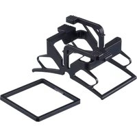
The mounting set makes it possible to install ifm sensors of types PQSxxx and PQCxxx in a panel.
3 Installation
▶ In a panel with a maximum thickness of 6 mm, make a 31 mm x 31 mm cutout (-0.4 mm tolerance each).

Fig. 1: Panel mounting using a fixing clamp (panel cutout; front view; rear view)
▶ Insert the device into the cutout in the panel from the back.
▶ Slide the frame of the mounting set (1) over the device from the front and attach it by engaging the two lateral protruding sections (2) into the recesses (3) on both sides of the device.
▶ Slide the fixing clamp of the mounting set onto the device from behind. The locating lugs of the fixing clamp (4) will latch in the jagged recesses on both sides of the device (5). Push until the device is firmly in place.

Fig. 2: Panel mounting with mounting set
Removal:
▶ Press the levers (6) and (7) of the fixing clamp together on both sides in the direction of the arrows and remove the fixing clamp.
▶ Lever off the frame (1) at the front.
▶ Remove the device from the wall fixture.

Fig. 3: Removal
Panel mounting of multiple devices:

Fig. 4: Horizontal installation for devices with M8 connector; n = number of devices
The dimensions apply to the use of ifm connectors with angled M8 sockets. If straight cable sockets are used, the distance must be increased.

Fig. 5: Horizontal installation for devices with M8 connector; n = number of devices
The dimensions apply to the use of ifm connectors with straight M8 sockets. Angled sockets cannot be used.
Brand : IFM
Model : E30574
Category : Electrical assembly kit