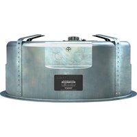
CMS 801 PI 8 OHM BACKCAN - Speaker TANNOY - Free user manual and instructions
Find the device manual for free CMS 801 PI 8 OHM BACKCAN TANNOY in PDF.


| Product Type | In-ceiling speaker (ceiling loudspeaker) |
| Brand | Tannoy |
| Model | CMS 801 PI 8 OHM BACKCAN |
| Category | Audio speaker |
| Cutout diameter | 295 mm |
| Rated power (transformer) | 60 W, selectable at 60/30/15 W (7.5 W at 70.7 V) |
| Impedance | 8 ohms (low impedance mode) or distributed line 70/100 V |
| Approximate weight | 4.5 kg (with back can) |
| Chassis material | Steel with resistant finish |
| Supplied accessories | C-ring, tile bridge, grille, cutout template, paint mask |
| Additional options | Mud ring, pre-installation back can (PI) |
| Installation | Suspended ceilings or drywall (SheetRock) |
| Recommended torque | 1.5 Nm (do not overtighten) |
| Connectivity | 4-pin Euroblock connector (pin 1 +, pin 2 -, pins 3/4 parallel) |
| Power | Passive (powered by external amplifier) |
| Safety instructions | Do not open, do not expose to water, use BX conduit for grounding, secondary attachment mandatory per local codes |
| Maintenance | Clean with a dry cloth, do not use solvents |
| Warranty | Music Tribe limited warranty (see musictribe.com/warranty) |
| Compliance | UL1480 (BX conduit required for grounding), WEEE directive 2012/19/EU |
Frequently Asked Questions - CMS 801 PI 8 OHM BACKCAN TANNOY
User questions about CMS 801 PI 8 OHM BACKCAN TANNOY
0 question about this device. Answer the ones you know or ask your own.
Ask a new question about this device
Download the instructions for your Speaker in PDF format for free! Find your manual CMS 801 PI 8 OHM BACKCAN - TANNOY and take your electronic device back in hand. On this page are published all the documents necessary for the use of your device. CMS 801 PI 8 OHM BACKCAN by TANNOY.
USER MANUAL CMS 801 PI 8 OHM BACKCAN TANNOY
EN
ES
FR
DE
PT
IT
NL
SE
PL
CMS 801 Series
CMS 801 SUB BM/CMS 801 SUB PI
8" Compact Ceiling Mounted Subwoofer for Installation Applications
(Blind Mount)/(Pre-Install)
CMS 801 PI 8 OHM BACKCAN
Back Can for CMS 801 PI Series Ceiling Loudspeakers (Pre-Install)
2 CMS 801 Series Quick Start Guide 3
EN
ES
EN Important Safety Instructions

Terminals marked with this symbol carry electrical current of sufficient magnitude to constitute risk of electric shock. the only high quality professional speaker tables with 15" TS or twist-locking plugs pre installed. All other installation or modification should be performed only by qualified personnel.
This symbol, wherever it appears, alerts you to the presence of uninsulated dangerous voltage inside the enclosure – voltage that may be sufficient to constitute a risk of shock.
This symbol, wherever it appears, alerts you to important operating and maintenance instructions in the accompanying literature. Please read the manual.
Caution To reduce the risk of electric shock, do not remove the top cover (or the rear section). No user serviceable parts include. Refer servicing to qualified personnel.
Caution To reduce the risk of fire or electric shock, do not expose this appliance to rain and moisture. The apparatus shall not be exposed to dripping or splashing liquids and no objects filled with liquids, such as wares, shall be placed on the apparatus.
Caution These service instructions are for use by qualified service personnel only. To reduce the risk of electric shock do not perform any servicing other than that contained in the operation instructions. Repairs have to be performed by qualified service personnel.
- Read these instructions.
- Keep these instructions.
- Here all warnings.
- Follow all instructions.
- Do not use this apparatus near water.
- Clean only with dry cloth.
- Do not have any ventilation openings, install in accordance with the manufacturer's instructions.
-
Do not install near any heat sources such as rotators, heat registers, stoves, or other apparatus (including amplifiers) that produce heat.
-
Do not defeat the safety purpose of the polarized or grounding-type plug. A polarized plug has two blades with one wider than the other. A grounding-type plug has two blades and a third grounding proing. The wide blade or the third proing are provided for your safety. If the provided plug does not fit into your outlet, consult an electrician for replacement of the obsolete outlet.
-
Protect the power card from being walked on or pinched particularly at plugs, convenience receptacles, and the point where they exit from the apparatus.
- Use only attachments/accessories specified by the manufacturer.

- Use only with the cart, stand, tripod, bracket, or table specified by the manufacturer, or sold with the apparatus. When a cart is used, use caution when moving the cart/apparatus combination to avoid
injury from tip-over
-
Unplug this apparatus during lightning storms or when unused for long periods of time.
-
Refer all servicing to qualified service personnel. Servicing is required when the apparatus has been damaged in any way, such as power supply cord or plug in damaged, liquid has been spilled or objects have fallen into the apparatus, the apparatus has been exposed to rain or moisture, does not operate normally, or has been dropped.
-
The apparatus shall be connected to a MUNG socket outlet with a protective earthing connection.
-
Where the MAINS plug or an appliance coupler is used as the disconnect device, the disconnect device shall remain nearly operable.

- Correct disposal of this product: This symbol indicates that this product must not be disposed at with household waste, according to the WEE Directive (2012/19/EU) and
should be taken to a collection center formed for the recycling of waste electrical and electronic equipment (EEL). The misunderstanding of this type of waste could have a possible negative impact on the environment and human health due to potentially hazardous substances that are generally associated with EEL. At the same time, your cooperation in the correct disposal of this product will contribute to the efficient use of natural resources. For more information about where you can take your waste equipment for recycling, please contact your local city office, or your household waste collection service. 18. Do not install in a confined space, such as a book case or similar unit.
-
Do not place naked flame sources, such as lighted candles, on the apparatus.
-
Please keep the environmental aspects of battery disposal in mind. Batteries must be disposed-of at a battery collection point.
-
This apparatus may be used in tropical and moderate climates up to 45°C.
LEGAL DISCLAIMER
Music Tribe accepts no liability for any loss which may be suffered by any person who relies either wholly or in part upon any description, photograph, or statement contained herein. Technical specifications, appearances and other information are subject to change without notice. All trademarks are the property of their respective owners. Vidas, Klark Teknik, Lab Suggers, Lake, Tanney, Turbosound, TC Electronic, TC Helicon, Behringes, Sugera, Osterheim, Auratone, Aston Microphones and Coledudio are trademarks or registered trademarks of Music in The Global Brands Ltd. © Music Tribe Global Brands Ltd. 2021 All rights reserved.
LIMITED WARRANTY
For the applicable warranty terms and conditions and additional information regarding Music Tribe's Limited Warranty, please see complete details online at musictribe.com/warranty.
ES
BESCHRÄNKTE GARANTIE
Thank you for purchasing this Tannoy Ceiling Monitor System product. This product range is suited for high-level music and speech reinforcement applications requiring exceptional sonic quality with uncompromised reliability.
Unpacking
Every Tannoy product and accessory is carefully inspected before packing. After unpacking, please inspect your product to make sure no damage has occurred in transit. In the unlikely event of any damage, would you please notify your dealer immediately and retain your shipping carton, as your dealer may ask you to return the faulty unit to him for inspection.
Each CMS loudspeaker is packed in pairs and provided with the following accessories as standard: C Ring, tile-bridge kit, grille, cut-out template, and paint mask. A plaster (mud) ring is also available as an optional extra.
Safety Notices
Some regional construction codes require the use of a secondary method of securing loudspeakers in ceiling to provide security of a backup support. A secondary support line should be attached from the safety loop on the rear of the product to a source point on the ceiling. Please consult the relevant construction codes in your region.
When using a power driver to install the product it is essential to use the correct torque level settings to avoid over tightening and damage to the ceiling material or clamps. Recommended torque setting: 1.5km
Tamnoy will not be held responsible for any damages caused by the improper installation of these loudspeakers.
Electrical Safety Notice: In comply with the standard UL1480, metal - dad flexible conduit (BK) is required for connection to the terminal block for proper earth grounding. In order to comply with UL regulations, the PI back can must always be used with the GAS PI models.
WHAT
In order to comply with the authority for the 2017-28, described that it was required for the last time of which the payment amount was assumed at the date being the balance reserve value of the interest and the current tax rate may be further included in this case. For example, the amount of tax revenue is not defined as a result of the expected tax rate of 5% or 3%.
Introducción
The following table provides the information in English:
Introduction
The following table provides the results of the 2018 and 2019 results: (1) 1/2 for the 2018 results, and (2) for the 2019 results. The results are presented in Table 4.
Einführung
The use of the first part of the first part of the second part of the third part of the fourth part of the fifth part of the sixth part of the seventh part of the eighth part of the fifth part of the sixth part of the seventh part of the eighth part of the sixth part of the seventh part of the eighth part of the sixth part of the seventh part of the eighth part of the sixth part of the seventh part of the eighth part of the sixth part of the seventh part of the eighth part of the sixth part of the seventh part of the eighth part of the sixth part of the seventh part of the eighth part of the sixth part of the seventh part of the eighth part of the sixth part of the seventh part of the eighth part of the seventh part of the sixth part of the seventh part of the eighth part of the sixth part of the seventh part of the eighth part of the sixth part of the seventh part of the eighth part of the sixth part of the seventh part of the eighth part of the sixth part of the seventh part of the eighth part of the sixth part of the seventh part of the eighth part of the sixth part of the seventh part of the eighth part of the sixth part of the seventh part of the eighth part of the fifth part of the fifth part of the fifth part of the fifth part of the fifth part of the fifth part of the fifth part of the fifth part of the fifth part of the fifth part of the fifth part of the fifth part of the fifth part of the fifth part of the fifth part of the fifth part of the fifth part of the fifth part of the fifth part of the fifth part of the fifth part of the fifth part of the fifth part of the fifth part of the fifth part of the fourth part and then, for which all parts are not included in any particular section.
Introdução
In addition, the case design may be used to define the point of the 1980s. The case is currently, which is not possible to be used in the case of the 1980s. The case is also necessary to use a point of the 1980s. The case is also necessary to use a point of the 1980s.
Introduzione
For the following table, there are two sets of data points (e.g., 1502.893, 167.400, 170.400) and a set of data points (e.g., 1502.893, 167.400, 170.400) for the first three data points. The first three data points are set in the first three data points. For the second three data points, there are four sets of data points (e.g., 1502.893, 167.400, 170.400) and a set of data points (e.g., 1502.893, 167.400, 170.400) for the third three data points. For the fourth three data points, there are four sets of data points (e.g., 1502.893, 167.400, 170.400) and a set of data points (e.g., 1502.893, 167.400, 170.400) for the fourth three data points.
Introduktion
For the following described information, we have been obtained from the research of the research of the research of the research of the research of the research of the research of the research of the research of the research of the research of the research of the research of the research of the research of the research of the research of the research of the research of the research of the research of the research of the research of the research of the research of the research of the research of the research of the research of the research of the research of the research of the research of the research of
Wprowadzenie
A. In fact, the following example of the 1980s: (1) being a new, deepening tool, deepening tool, deepening tool, deepening tool, deepening tool, deepening tool, deepening tool, deepening tool, deepening tool, deepening tool, deepening tool, deepening tool, deepening tool, deepening tool, deepening tool, deepening tool, deepening tool, deepening tool, deepening tool, deepening tool, deepening tool, deepening tool, deepening tool, deepening tool, deepening tool, deepening tools, deepening tools, deepening tools, deepening tools, deepening tools, deepening tools, deepening tools, deepening tools, deepening tools, deepening tools, deepening tools, deepening tools, deepening tools, deepening tools, deepening tools, deepening tools, deepening tools, deepening tools, deepening tools, deepening tools, deepening tools, deepening tools, deepening tools, deepening tools, deepening tools, deepening tool
Product Feature Identification
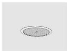
Fig 1.1: The blind-mount [BM] models come with a pre-fitted back can
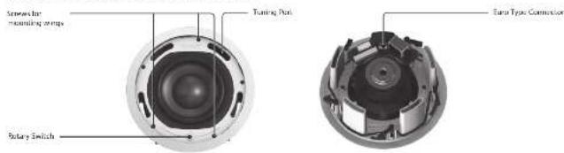
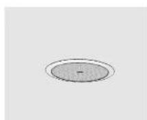
Fig 1.2: A pre-install [PI] model shown without optional pre-install back can
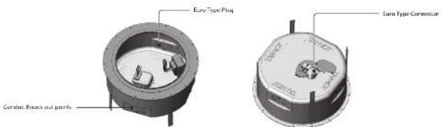
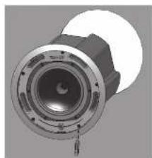
Fig 1.3: Optional pre-install (PI) back can for PI models
Note that the CMS 801 PI model's transformer is pre-attached to the CMS 801 PI back can for easy install.
Quick Star Guide
Accessories
Each product is supplied with the following accessories as standard:
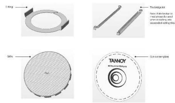
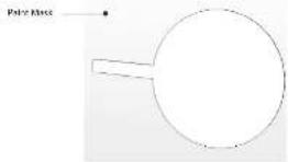
Optional accessories:
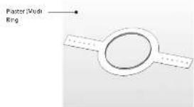
18 CMS BDI Series
Quick Star Guide 19
Mechanical Installation Guide for Suspended Ceilings Mechanical Installation Guide for SheetRock (Plasterboard) Ceilings
- Remove the ceiling tile from its frame and place it on a flat surface. Mark the cut-out area on the ceiling tile by tracing around the template provided.
- Cut out the hole in the ceiling tile using a circular save or pad saw.
- Place the C-ring and tile-bridge on top of the ceiling panel, aligning the C-ring over the hole, and screw the C-ring to the tile bridge using the fixings provided.
- Slide the speaker assembly through the hole and turn the screws on the front of the speaker to extend the mounting wings. Tighten the screws until a firm grip is achieved. If using a power driver, Tannoy recommends a torque setting of 1.5 km.
DO NOT OVERTIGHTEN!
- Slide the tie panel back into the suspended ceiling. The Tie bridge ends will catch over the railings, supporting the weight of the speaker.
Go to the 'Wiring and Setting Up' section for instructions on wiring and set-up instructions.
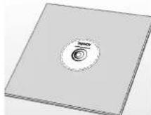
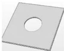
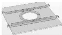
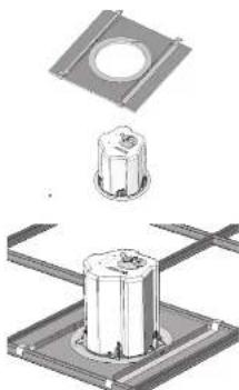
- Mark the cut-out area on the ceiling by tracing around the template provided.
- Cut out the hole in the ceiling using a circular saw or pad saw, then slide the C-ring into the ceiling, aligning it over the cut-out hole).
- Go to the 'Wiring and Setting Up' section for wiring and set-up instructions then return to point 4 below.
- Slide the speaker assembly through the hole and turn the screws to extend the mounting wings. Tighten the screws until a firm grip is achieved.
If using a power driver, Tannoy recommends a torque setting of 1.5 Nm. DO NOT OVERTIGHTEN! - Insert grille by pushing it onto the speaker.

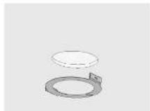
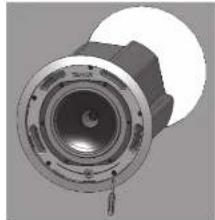
Mechanical Installation Instructions for Optional Plaster Ring:
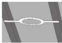
An optional plaster (mud) ring bracket is available from Tannoy. This bracket is designed to be pre-installed into newly constructed, non-suspended ceilings.
- Rail or screw the plaster ring to the joists.
-
Lay the speaker wiring to where the speaker will be fitted and complete the plastering work on the ceiling.
-
Cut out the hole in the ceiling using a circular saw or pad saw.

-
Go to the 'Wiring and Setting Up' section for instructions on wiring then return to point 5 below.
-
Slide the speaker assembly through the hole and turn the screws to extend the mounting wings. Tighten the screws until a firm grip is achieved.
If using a power driver, Tannoy recommends a torque setting of 1.5 Nm.
DO NOT OVERTIGHTEN!
- Insert grille by pushing it onto the speaker.
Instructions for Optional Pre-Installation Back can (Pi Models Only):
An optional pre-install back can is available for all pi (pre-install) models. This back can be designed to be pre-installed into newly constructed, non-suspended ceilings. Note that the CMS 801 PI model's transformer is pre-attached to CMS 801 PI back can for easy install.
- Attach the back can to the installed conduit. This can be attached in two ways:
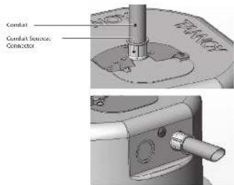
a. You can use the clamp at the back of the pre-install back can. The product will accept a squeeze connector with a thread size of up to 22 mm. To remove the cable clamp, simply uncrew the threaded washer (under the wiring cover) which holds the cable clamp in place and replace it with a conduit squeeze connector.
b. You can use any of the three knock-out points at the sides of the P1 back can (19 mm, 22 mm or 28 mm diameter);
-
Lay the speaker wiring to where the speaker will be fitted and complete the plastering work on the ceiling.
-
Cut out the hole in the ceiling using a circular saw or pad saw
-
Go to the 'Wiring and Setting Up' section for instructions on wiring and setting up then return to point S below.
-
Slide the speaker assembly through the hole and burn the screws to extend the mounting wings. Tighten the screws until a firm grip is achieved. If using a power driver, Tamnoy recommends a torque setting of 1.5 Nm.
DO NOT OVERTIGHTEN!
Wiring And Setting Up: CMS 801 sub BM Dimensions:
-
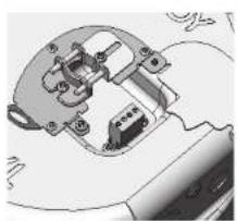
Open the wiring cover at the back of the speaker can to access the Euro type connector plug and socket.
-
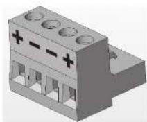
For connection to an amplifier, use pins 1 and 2:
- Pin 1 is positive
- Pin 2 is negative
For conversion to additional speakers in a distributed line, pins 3 and 4 are in parallel where:
• Pin 3 is negative
- Pin 4 is positive
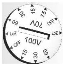
- Close the wiring cover and tighten both screws on the cable clamp. Use the rotary switch located on the front of the unit to select whether you wish to use the speaker in a low-impedance or distributed-line application.
THE SPEAKER IS SUPPLIED IN LOW IMPEDANCE MODE. NEVER CONNECT THE SPEAKER TO A 70/100 VOLT AMPLIFIER WHILE IT IS SET FOR LOW IMPEDANCE.
All CWS 801 models use a 60 W transformer. When using distributed-line systems, the transformer can be tapped at 60 W, 30 W and 15 W, with an additional 7.5 W tapping for 70.7 V line systems.
Template hole cutout size: 295 mm
![310.5 [72.22] 18.5 [0.79] 327.8 [12.07]](/content/2026/04/701194/images/463d97ab2b64c2342ca9ce983899ac418f02a3367deb983cf28be39bbc1707bf.jpg)
![2086.4 [1:27]](/content/2026/04/701194/images/14a3d882d3f360fee573c71b314e0f0d4293eeded8d85b0e84c5d4b6f77b0b16.jpg)
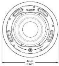
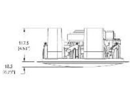
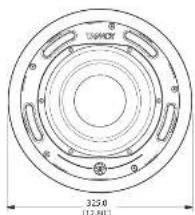
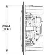
CMS 801 sub PI Dimensions:
Template hole cutout size: 295 mm
CMS 801 PI Back Can Dimensions:
Template hole cutout size: 295 mm
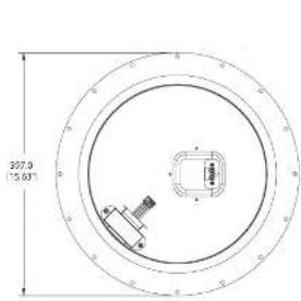
![198.5 [6.63] 291.4 [17.47] 365.0 [14.37] 8.8 [0.33] 151.2 [3.97]](/content/2026/04/701194/images/ebc2be4d12602b58a2c4e8903049e16704ba891a90002056601d15bbdaf12058.jpg)
24 CMS 801 Series Quick Start Guide 25
CMS 801 PI Back Can Dimensions:
Template hole cutout size: 295 mm
Product Feature Identification
| System | |
| Frequency response (1-3 dB) * 56 Hz = 160 Hz | |
| Frequency range: 1.10 dB* 47 Hz = 100 Hz | |
| System sensitivity (1 V*2 h)* m*2 | 92 dB (1W = 2.45 V for 8 Chms) |
| Rated maximum SPL * | 112 dB (average) 116 dB (peak) |
| With THP-60 | 110 dB (average) |
| Power Handling* | |
| Average 100 W | |
| Programme 250 W | |
| Peak 400 W | |
| Recommended amplifier power 200 V @ 8 Ohms | |
| Nominal Impedance 8 Ohms | |
| Transformer Taps (via front rotary switch) | |
| Input signal frequency range: 58 Hz = 20 Hz | |
| 70 V 60 V/30 V/13 5V/7.5 V/OFF & Low impedance operation * Refer to note 4* | |
| 100 V 60 V/30 V/13 5V/OFF & Low impedance operation * Refer to Noise 4* | |
| Crossover | Integral 2nd order passive, 160 Hz |
| Transducers | |
| Low frequency | 1x 200 mm (8.0V) long throw wooder with multi fibre paper pulp cone |
| High frequency | |
| Endosure | |
| Back can | Zinc plated steel |
| Brillie | Reflex bandot UL 54V-8 rodent ABS |
| Grelle | Steel, with weather resistant coating |
| Safety Features | Safety ring located at rear of maximum-for load heating safety bond |
| Camping Design | Security toggle clamp |
| Transducers | |
| Backcan Options | |
| Blind Island (BNK) | Complete with fixed back can |
| Pre install (PS) | Separate back can for pre installation |
| Cable Entry Options | Cable clamp & sourceze connector for conduct up to 22mm |
| Conduit Resinouts | 3 Sets of horizontal positions 19 / 22 / 28 mm (0.75 / 0.87 / 1.1*) |
| Connectors | Retrotable locking connector with screw terminals with "loop through" facility |
| Safety agency micings (pending) | UL-1490, UL-2040, CE |
| BMC cable cutout diameter | 295 mm (11.6") |
| P Chile cable diameter | 295 mm (11.6") |
| Dimensions | |
| Bezel diameter | 325 mm (12.68") |
| Front of ceiling to rear of back can (BM) | 310.5 mm (13.32") |
| Front of ceiling to top of safety loop (BM) | 327.8 mm (12.92") |
| Back of ceiling surface to rear of back can (PI) | 151.2 mm (5.95") |
| Back of ceiling surface to top of safety loop (PI) | 168.5 mm (6.63") |
| Front of ceiling to rear of basic parts (no back can PI) | 123.7 mm (4.87") |
| Net Weight (kg) | |
| CKS 501 BM | 8.4 kg (18.48 lbs) |
| CKS 501 PI | 4.7 kg (10.34 lbs) |
| PI back can | 4.2 kg (9.25 lbs) |
| Included Accessories | C Ring, tile bridge, paint mask, outlet template, grille |
| Optional Accessories | Plaster (Msd) Ring |
(1)
[1] The following table provides the information in English:
(1) We group some of us, we and an all-branded unaided common. The draper in place with the same system [7], means of the secret, but minimum 30 can be set. (2) We view some brader property for this: 4-W (not a) described security, perform data, and low levels of household environment.
SOTIC TATIXV2,okem,etin 0153017m,dibie w,mudie 4.optional (PbJou)
for any time, the time is not to be taken. The time is not to be taken.
We are by the best spot for a new setting with a location
| Ordering Information | |||
| Model name | Baffle / Grille Colour | Packed Quantity | Packed weight kg (lbs) |
| CMS-801 SUB BIA | WHITE | 2 | 20.2 (24.44) |
| CMS-801 SUB PII | WHITE | 2 | 12.2 (26.64) |
Other important information

Important information
- Register online. Please register your new Music Tribe equipment right after you purchase it by visiting musichibe.com. Registering your purchase using our simple online form helps us to process your repair claims more quietly and efficiently. Also, read the terms and conditions of our warranty, if applicable.
- Malfunction. Should your Music Tribe Authorized Reveller not be listed in your vicinity, you may contact the Music Tribe Authorized Further for your country listed under "Support" at musicitibe.com. Should your country not be listed, please check if your problem can be dealt with by our "Online Support" which may also be found under "Support" at musicitibe.com. Alternatively, please submit an online warranty claim at musicitibe.com BEFORE returning the product.
- Power Connections, before plugging the unit into a power socket, please make sure you are using the correct mains voltage for your particular model. Equity lines must be replaced with fuses of the same type and rating without exception.

Hereby, Music Tribe declares that this product is in compliance with Directive
2011/65/EU and Amendment 2015/B63/EU, Directive 2012/19/EU, Regulation
519/2012 REACH SWHC and Directive 1907/2006/LC, and this passive product is not
applicable to EMC Directive 2014/30/EU, LV Directive 2014/35/EU.
Full text of ELLoC is available at https://community.musicribe.com/
EU Representative. Music Tribe Brands DKA/S
Address: In Spang Olsens Gade 17, DK - 3200 Aarhus N, Denmark
EN

- CMS 801 SERIES
- LEGAL DISCLAIMER
- LIMITED WARRANTY
- BESCHRÄNKTE GARANTIE
- UNPACKING
- SAFETY NOTICES
- INTRODUCCIÓN
- INTRODUCTION
- EINFÜHRUNG
- INTRODUÇÃO
- INTRODUZIONE
- INTRODUKTION
- WPROWADZENIE
- PRODUCT FEATURE IDENTIFICATION
- ACCESSORIES
- MECHANICAL INSTALLATION GUIDE FOR SUSPENDED CEILINGS MECHANICAL INSTALLATION GUIDE FOR SHEETROCK (PLASTERBOARD) CEILINGS
- DO NOT OVERTIGHTEN
- MECHANICAL INSTALLATION INSTRUCTIONS FOR OPTIONAL PLASTER RING
- INSTRUCTIONS FOR OPTIONAL PRE-INSTALLATION BACK CAN (PI MODELS ONLY)
- WIRING AND SETTING UP: CMS 801 SUB BM DIMENSIONS
- CMS 801 PI BACK CAN DIMENSIONS
- OTHER IMPORTANT INFORMATION
- IMPORTANT INFORMATION
Brand : TANNOY
Model : CMS 801 PI 8 OHM BACKCAN
Category : Speaker