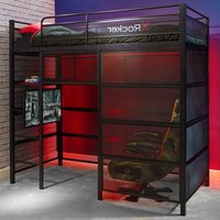
Battle Den - Bed X Rocker - Free user manual and instructions
Find the device manual for free Battle Den X Rocker in PDF.


| Product Type | Bunk bed |
| Brand | X Rocker |
| Model | Battle Den |
| Recommended Use | Domestic, children aged 6 and up for the top bunk |
| Mattress dimensions (top bunk) | Length: 74-75 inches (188-191 cm); Width: 37.5-38.5 inches (95-98 cm); Thickness: 4 to 6 inches (10-15 cm) |
| Main material | Wood or metal (not specified, to be confirmed) |
| Estimated assembly time | Approximately 3 hours |
| Recommended number of people for assembly | 2 (ideally 3) |
| Maximum supported weight (top bunk) | Not specified, but designed for children and teenagers |
| Product weight | Estimated: 50-80 kg (not provided) |
| Safety features | Guardrails on both sides of the top bunk; safety bars; included ladder; warning labels |
| Maintenance and cleaning | Periodically check bolts and nuts; clean with a damp cloth; avoid abrasive products |
| Spare parts and repairability | Pre-assembled parts available for replacement; contact customer service at 866-969-2603 |
| Important warnings | Do not use for children under 6 on the top bunk; do not jump; use the ladder; do not hang objects from the guardrails |
| Warranty | Not specified in the manual |
Frequently Asked Questions - Battle Den X Rocker
User questions about Battle Den X Rocker
0 question about this device. Answer the ones you know or ask your own.
Ask a new question about this device
Download the instructions for your Bed in PDF format for free! Find your manual Battle Den - X Rocker and take your electronic device back in hand. On this page are published all the documents necessary for the use of your device. Battle Den by X Rocker.
USER MANUAL Battle Den X Rocker
natural_image
Isometric line drawing of a multi-level metal shelving unit with perforated panels and grid patterns (no text or symbols)Dimensions
Width -77.7in
Depth - 41.3in
Height - 72in
NEED HELP?
EMAIL:SUPPORT@XROCKERGAMING.COM
BESOIN D'AIDE?
COURRIEL:SUPPORT@XROCKERGAMING.COM
¿NECESITAS AYUDA?
CORREO ELECTRÓNICO:SUPPORT@XROCKERGAMING.COM
IMPORTANT: You must keep your original retail receipt as proof of purchase.
Read Before Beginning Assembly
- Call 866-969-2603 if you need assistance.
- Work in a spacious area and near where the unit will be used, preferably on a carpet, or use a piece of the cardboard packaging to protect your floor and product.
- Recommended # of people needed for assembly: 2 (however it is always better to have an extra hand).
• Estimated assembly time is 3 hours. - Make sure all parts are included. Most parts are labeled or stamped on the raw edge.
- Read each step carefully. It is very important that each step of the instructions is performed in the correct order. If these steps are not followed in sequence, assembly difficulties will occur.
Caution
- This product is designed for home use and not intended for commercial use.
- This product contains small components. Please ensure that they are kept away from small children.
- Clean the product with a soft damp cloth. DO NOT use harsh chemicals or abrasive cleaners.
- Periodically check and ensure that the guardrail, ladder, and other components are in their proper position, free from damage, and that all connectors are tight.
Handy Hints
- Move your new furniture carefully, with two people lifting and carrying the unit to its new location.
- Your furniture can be disassembled and reassembled to move.
- Assemble all parts and bolts loosely during assembly, only once the product is complete should you fully tighten the bolts
- Regularly check and ensure that all bolts and fittings are tightened properly.
WARNINGS
- Follow the information on the warnings appearing on the upper bunk end structure and on the carton. Do not remove warning label from bed.
- Always use the recommended size mattresses or mattress supports, or both, to help prevent the likelihood of entrapment or falls.
- Use only a mattress which is 74"-75" long and 37 12 " - 38 12 " wide on upper bunk.
- Ensure thickness of mattress on upper bunk is greater than 4" and that it does not exceed 6".
- Surface of mattress must be at least 5" (127 mm) below the upper edge of guardrails.
- Do not allow children under 6 years of age to use the upper bunk.
- Do not allow horseplay on or under the bed and prohibit jumping on the bed.
- Prohibit more than one person on upper bunk.
- Always use the ladder for entering and leaving the upper bunk.
- Do not use substitute parts. Contact the manufacturer or dealer for replacement parts.
- Use of a night light may provide added safety precaution for a child using the upper bunk.
- Always use guardrails on both long sides of the upper bunk. If the bunk bed will be placed next to the wall, the guardrail that runs the full length of the bed should be placed, against the wall to prevent entrapment between the bed and wall.
- The use of water or sleep flotation mattresses is prohibited.
- STRANGULATION HAZARD-Never attach or hang items to any part of the bunk bed that are not designed for use with the bed; for example, but not limited to, hooks, belts and jump ropes.
- Keep these instructions for future reference.
Please check you have all the panels listed below
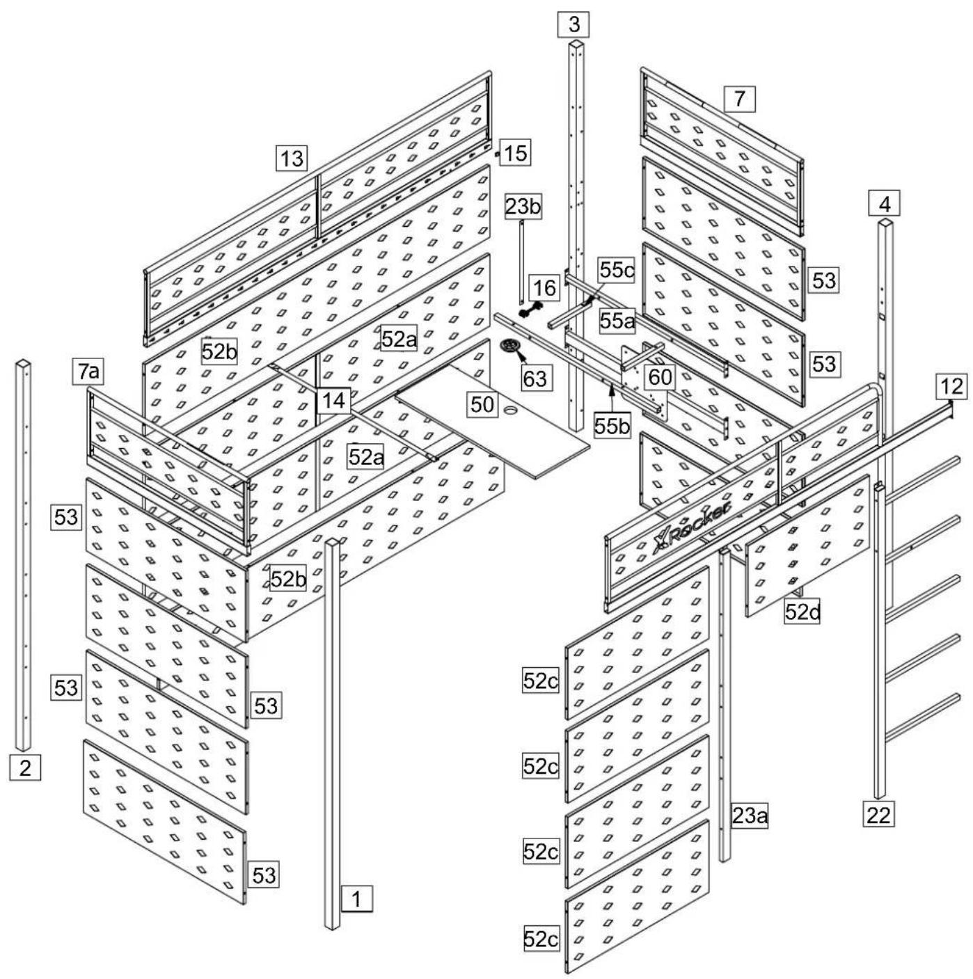
Components - Panels
Please check you have all the panels listed below
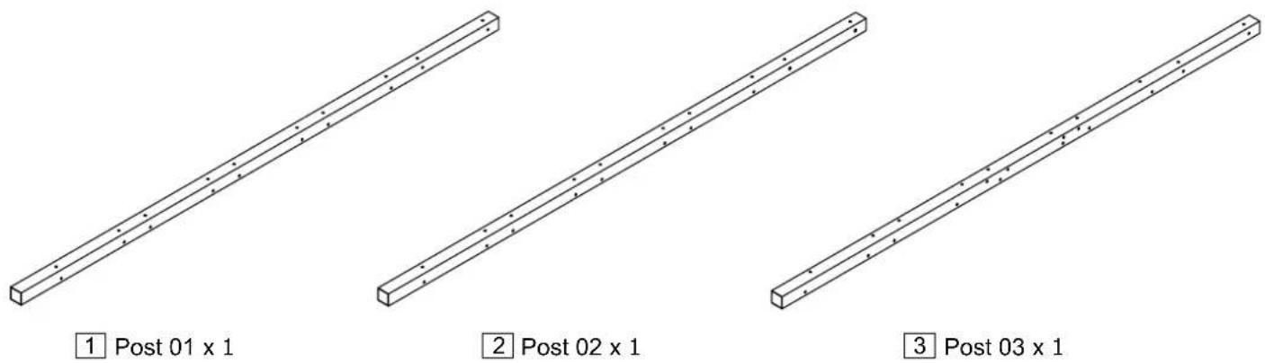
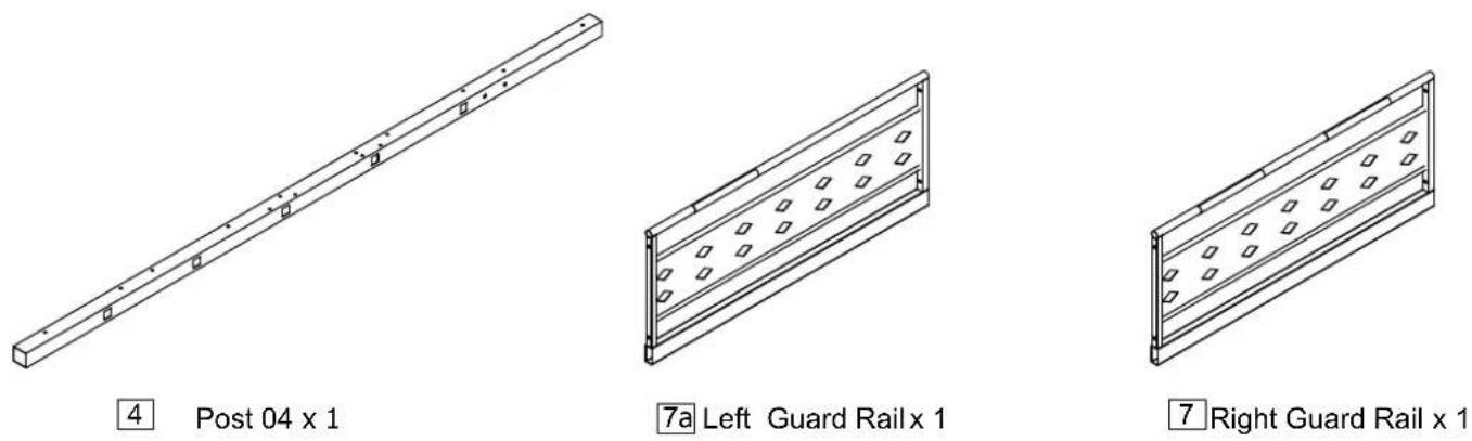
Components - Panels
Please check you have all the panels listed below
natural_image
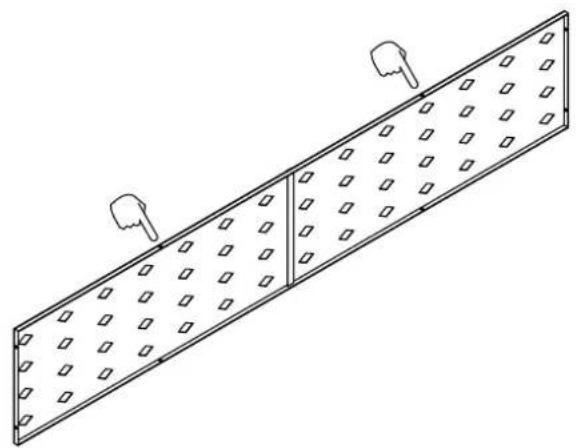
Isometric line drawing of a rectangular plate with perforated sides and two small circular objects on top (no text or symbols)52a Rear Mesh Panel 01 x 2
natural_image
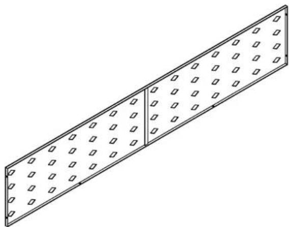
Isometric line drawing of a rectangular plate with perforated edges and square holes (no text or symbols)52b Rear Mesh Panel 02 x 2

natural_image
Isometric line drawing of a rectangular plate with evenly spaced square holes (no text or symbols)52c Front Mesh Panel 01 x 4
natural_image
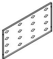
Isometric view of a rectangular panel with evenly spaced square holes (no text or symbols)52d Front Mesh Panel 02 x 1
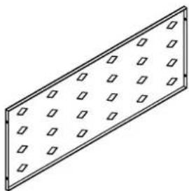
natural_image
Isometric view of a rectangular plate with evenly spaced square holes (no text or symbols)53 Side Mesh Panel x 8
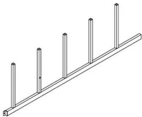
natural_image
Isometric line drawing of a wooden beam with five vertical posts (no text or symbols)22 Ladder x 1
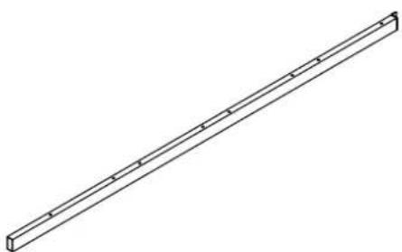
natural_image
Isometric line drawing of a long rectangular beam with evenly spaced notches (no text or symbols)23a Support Post 01 x 1
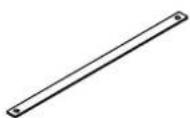
23b Support Post 02 x 1
Components - Panels
Please check you have all the panels listed below
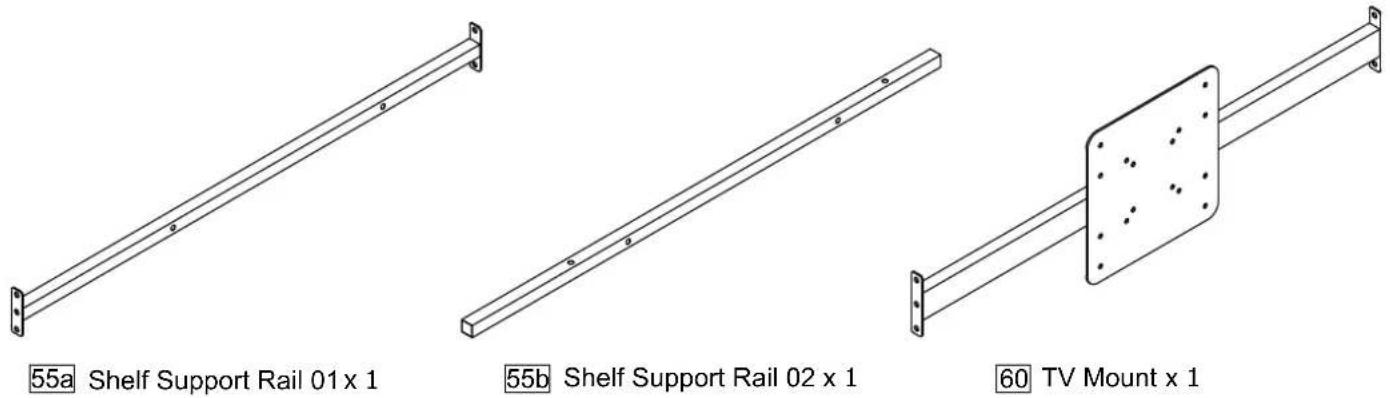
55c Shelf Support Rail 03 x 2

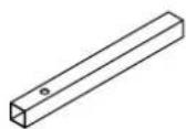
63 Cable Cap x 1
natural_image
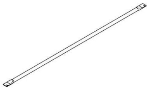
Simple line drawing of a straight diagonal line with two small square end markers at both ends (no text or symbols)14 Slats x 24

15 Plastic Plug x 48
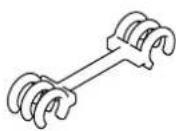
16 Slat Spacer x 23
Components - Fittings
Please check you have all the panels listed below
Note: The quantities below are the correct amount to complete the assembly. In some cases more fittings may be supplied are required.
A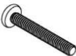 45mm M6 Bolt x 5 45mm M6 Bolt x 5 | C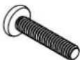 30mm M6 Bolt x 15 30mm M6 Bolt x 15 | E 25mm M6 Bolt x 11 25mm M6 Bolt x 11 |
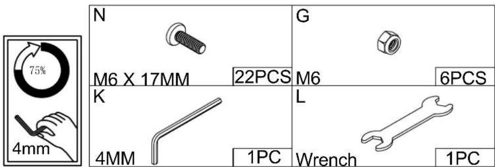
N 17mm M6 Bolt x 85 17mm M6 Bolt x 85 | G[24CG]M6 x 6 | H M6 Spring Washer x 8 M6 Spring Washer x 8 |
| I[3T32]M6 Metal Washer x 8 | J M6 Plastic Washer x 8 M6 Plastic Washer x 8 | K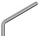 Allen Key 4mm x 1 Allen Key 4mm x 1 |
L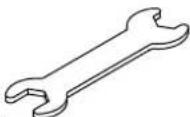 Wrench x 1 Wrench x 1 | M M4 Metal Washer x 4 M4 Metal Washer x 4 |
Tools required

Ruler/tape measure
| 0 | 5 | 10 | 15 | 20 | 25 | 30 | 35 | 40 | 45 | 50 | 55 | 60 | 65 | 70 | 75 | 80 | 85 | 90 | 95 | 100 | 105 | 110 | 115 | 120 | 125 | 130 | 135 | 140 | 145 | 150 | 155 | 160 | 165 | 170 |
Assembly Instructions
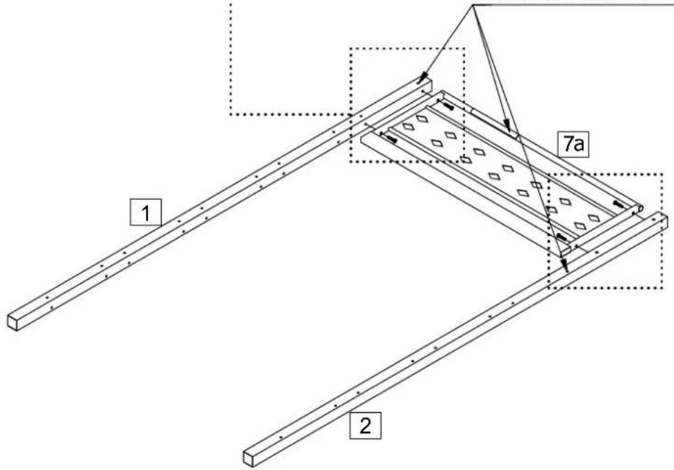
Step 1
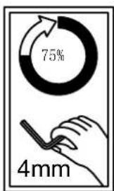
Attach Left Guard Rail 7a x 1 to Post 01 1 and Post 02 2 with C.
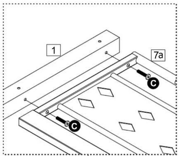
Warning label on 7a must be oriented on the same side as the side rail holes

Assembly Instructions
Step 2
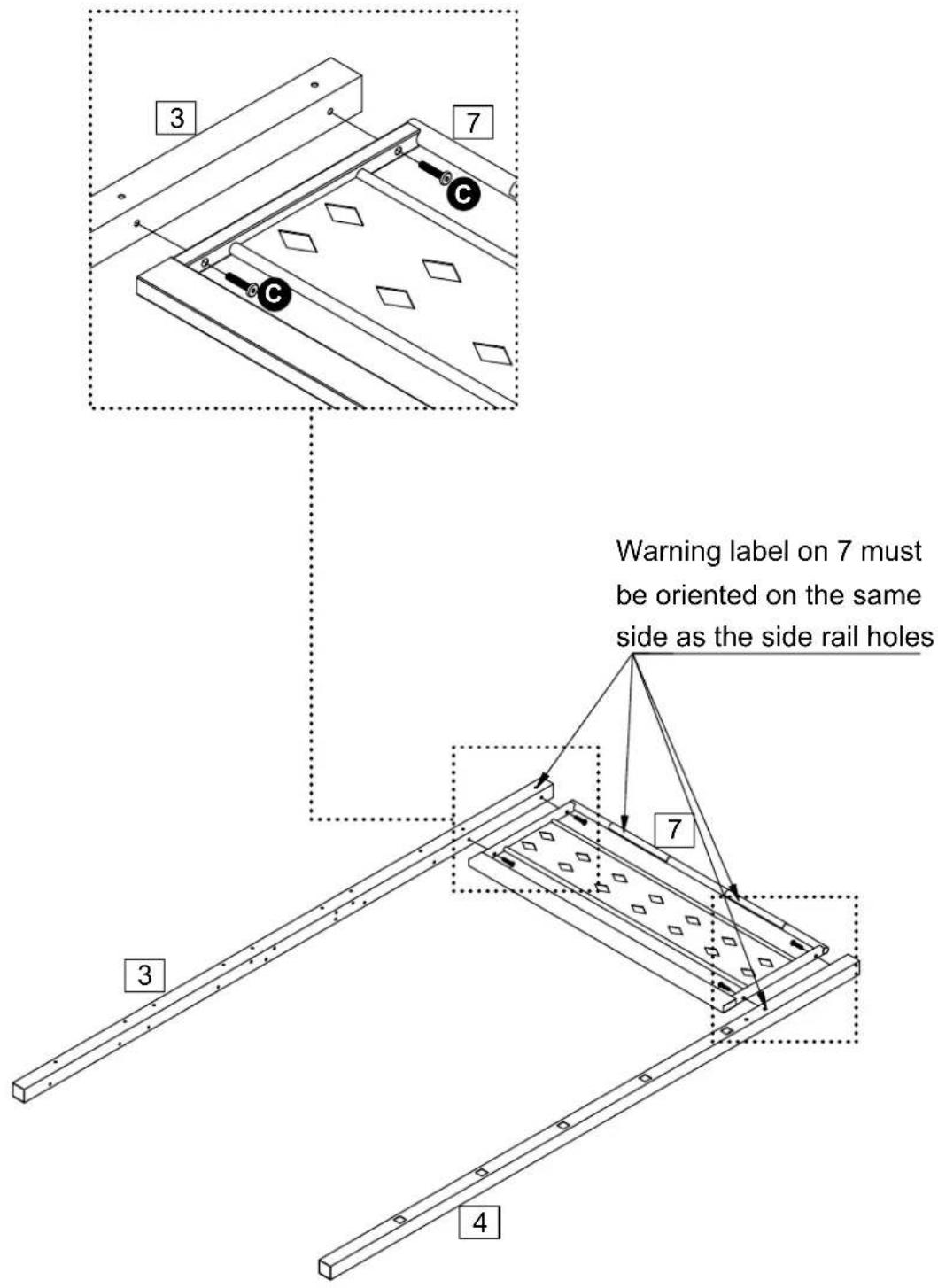
Attach Right Guard Rail 7 x 1 to Post 03 3 and Post 04 4 with C.
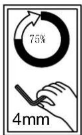
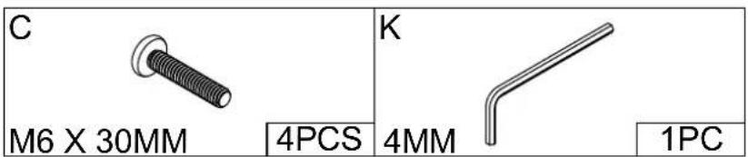
Assembly Instructions
Step 3
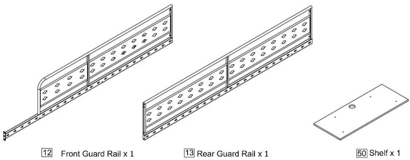
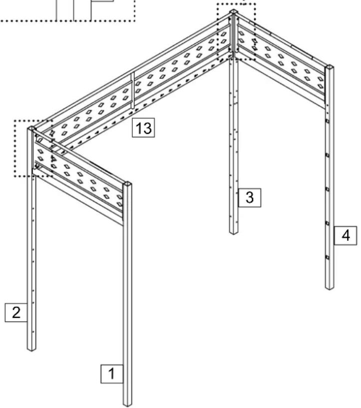
Attach Rear Guard Rail 13
to Post 02 2 and Post 03
3 with C, H, I, J.
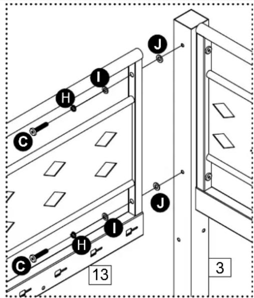
C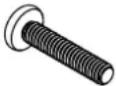 M6 X 30MM M6 X 30MM | 4PCS | H[IMAGE]M6Spring Washer | 4PCS |
I M6Metal Washer M6Metal Washer | 4PCS | JM6Plastic Washer | 4PCS |
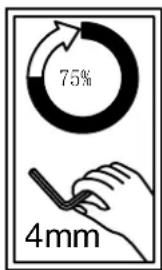
K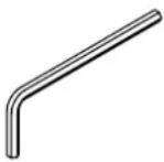 4MM 4MM | 1PC | ||
Assembly Instructions
Step 4
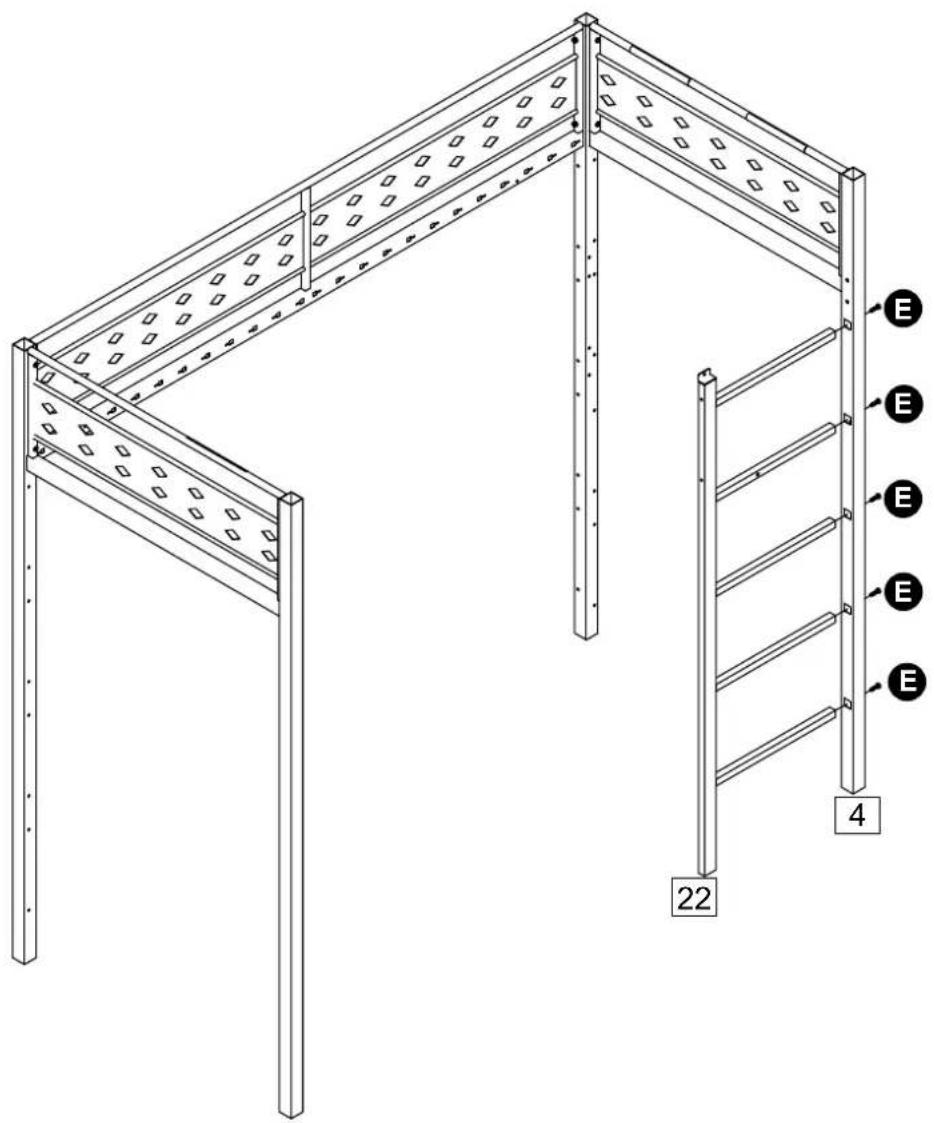
Attach Ladder 22 to Post 04 4 with E.
Assembly Instructions
Step 5
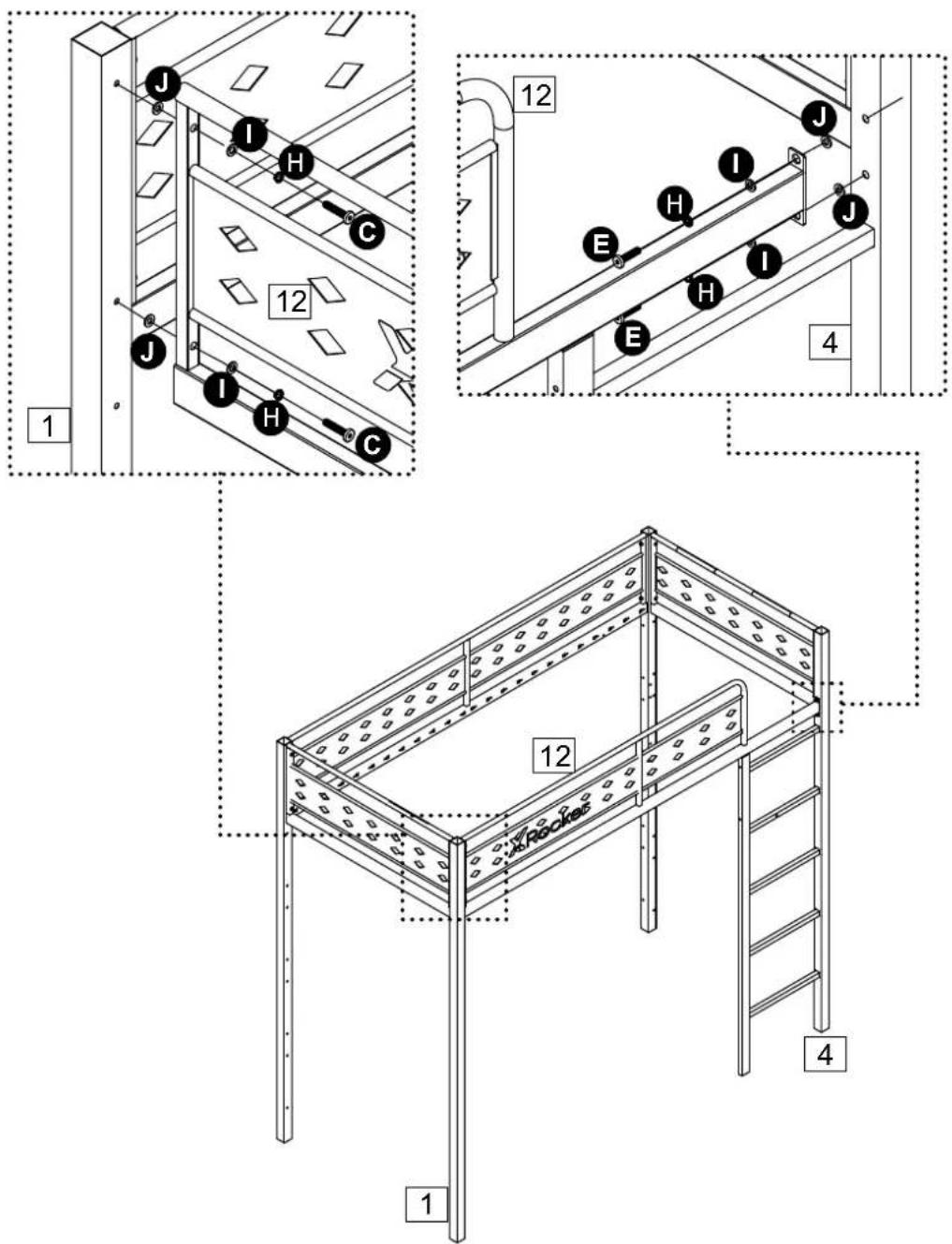
Attach Front Guard Rail 12
to Post 01 1 with C, H,
I, J and Post 04 4
with E, H, I, J.
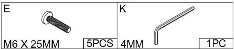
C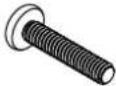 | E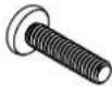 | ||
| M6 X 30MM | 2PCS | M6 X 25MM | 2PCS |
| H[57x2] | I | ||
| M6Spring Washer | 4PCS | M6Metal Washer | 4PCS |
J | K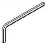 | ||
| M6Plastic Washer | 4PCS | 4MM | 1PC |
Assembly Instructions
Step 6
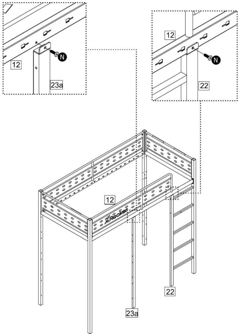
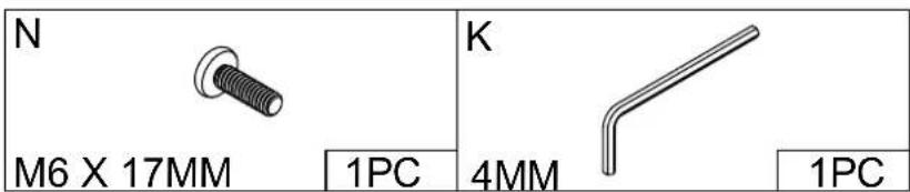
Attach Support Post 0123a to Front Guard Rail12 with N.
Then screw N to Ladder 22 .
Assembly Instructions
Step 7
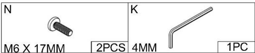
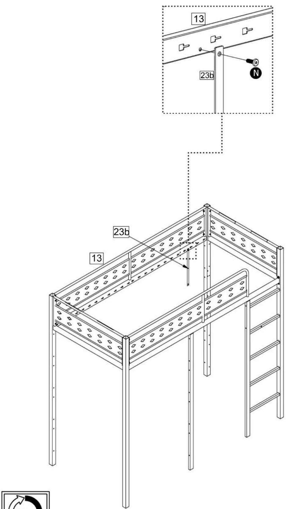
Attach Support Post 0223b to Rear Guard Rail 13 with N.
Assembly Instructions
Step 8
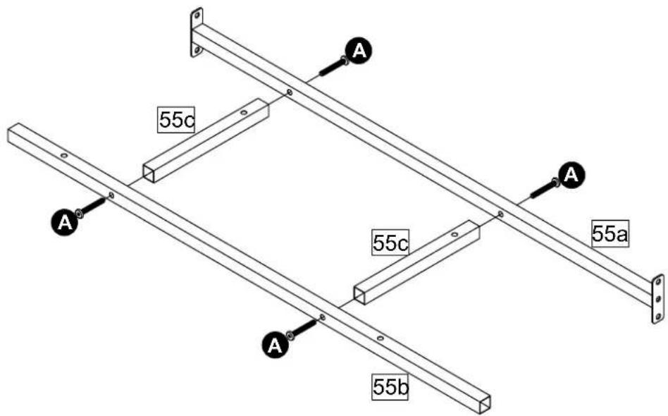
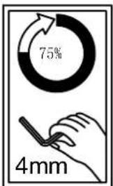
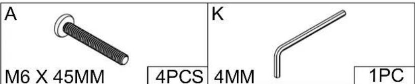
Attach Shelf Support Rail 03 55c x 2 to Shelf Support Rail 01 55a and Shelf Support Rail 02 55b with A.
Assembly Instructions
Step 9
Attach Shelf Support Rail 0155a to Post 033 and Post 044 with N, then Shelf Support Rail 0255b to Support Post 0223b and Ladder22 with C, A
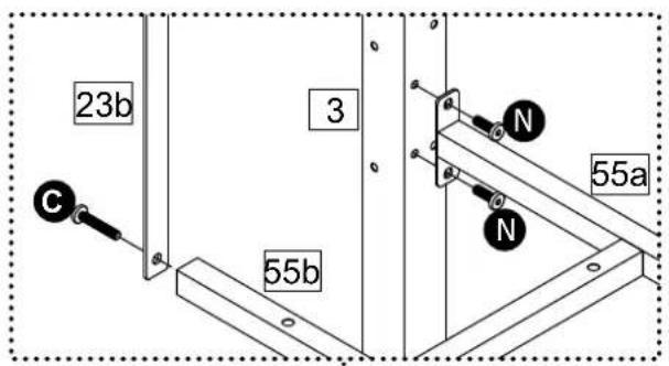
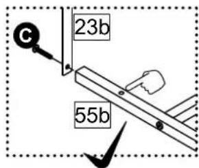
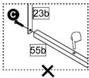
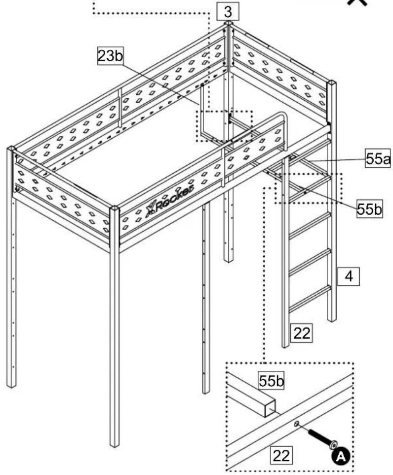
A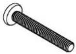 | C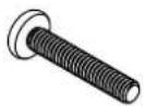 | ||
| M6 X 45MM | 1PC | M6 X 30MM | 1PC |
N | K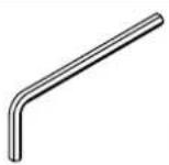 | ||
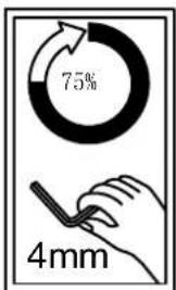
| M6 X 17MM | 4PCS | 4MM | 1PC |
Assembly Instructions
Step 10
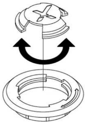
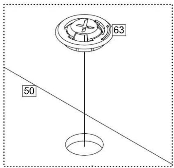
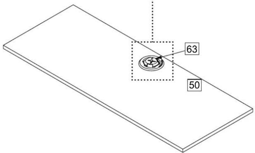
Attach Cable Cap 63 to Shelf 50.
natural_image
Diagram of a mechanical component with arrows indicating rotation or assembly (no text or symbols)The cover could be removed before passing through the cable and assembled back when finished.
Assembly Instructions
Step 11
Attach Shelf 50 to Shelf
Support Rail 03 55c x 2 and
Support Rail 02 55b with E.
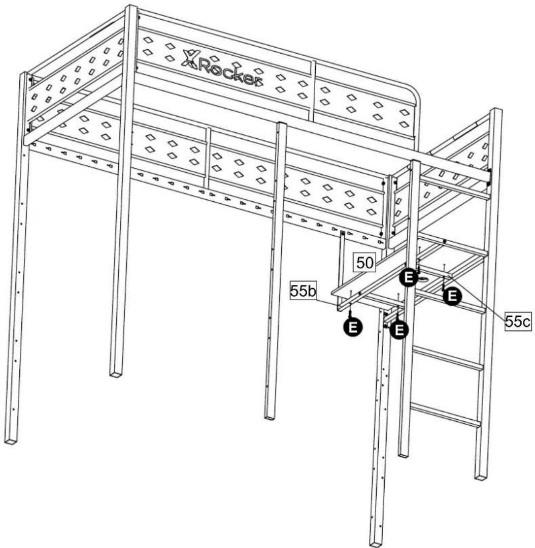
| E | M6 X 25MM | 4PCS | K | 4MM | 1PC |
Assembly Instructions
Step 12
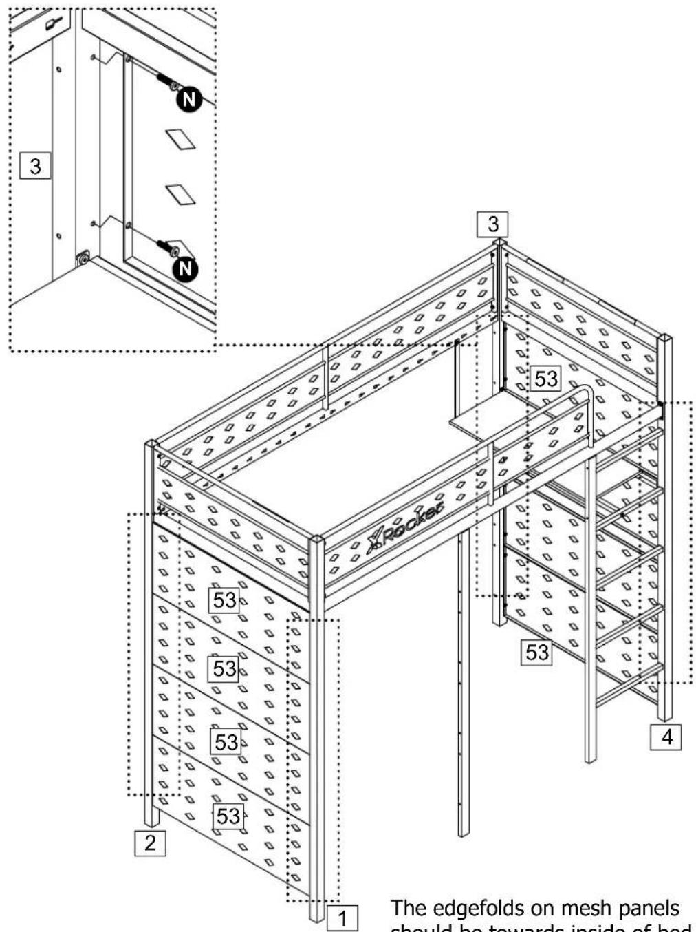
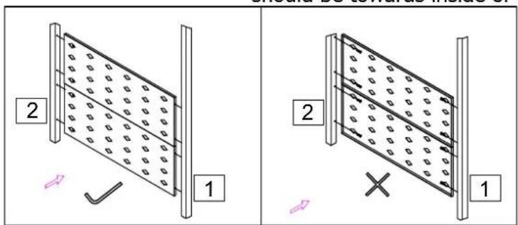
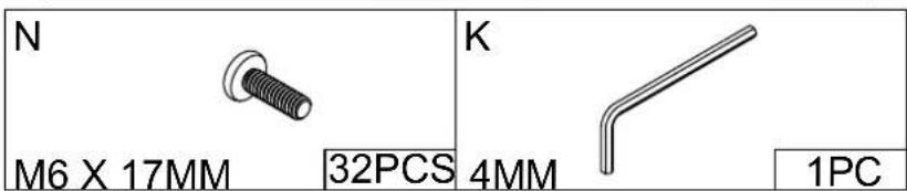
Attach Side Mesh Panel 53 x 8 to Post 01 1 , Post 02 2 and Post 03 3 , Post 04 4 with N .
Assembly Instructions
Step 13
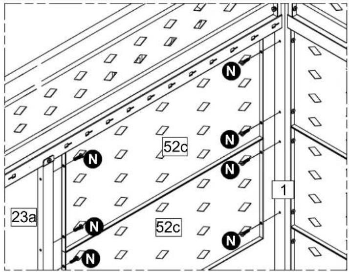
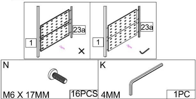
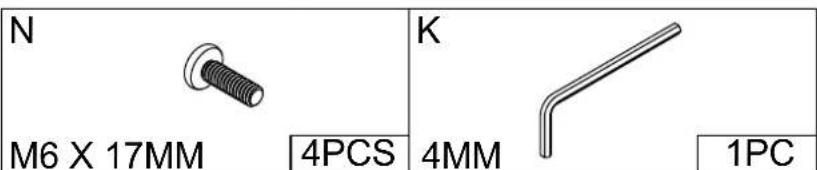
Attach Front Mesh Panel 01
52c x 4 to Post 01 1 and
Support Post 01 23a with
N
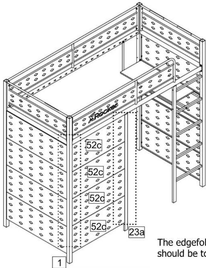
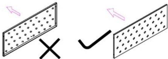
The edgefolds on mesh panels should be towards inside of bed.
Assembly Instructions
Step 14
Attach Front Mesh Panel 02 52d to Support Post 01 23a and Ladder 22 with N.
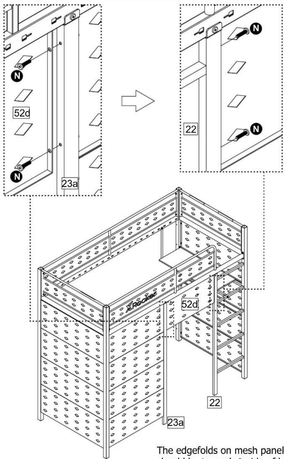
The edgefolds on mesh panels should be towards inside of bed.
Assembly Instructions
Step 15
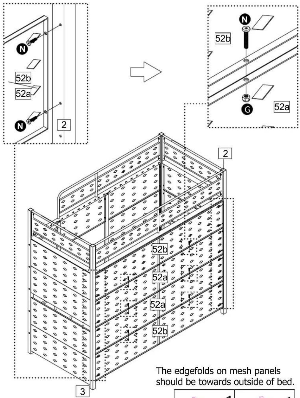
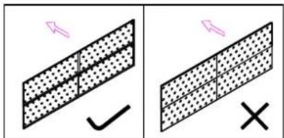
Attach Rear Mesh Panel 01
52a x 2 and Rear Mesh
Panel 02 52b x 2 to Post 02
2 and Post 03 3 with N.
Attach Rear Mesh Panel 02
52b x 2 to Rear Mesh Panel
01 52a x 2 with N, G.
Attach Rear Mesh Panel 01
52a x2 together with N G.
Assembly Instructions
Step 16
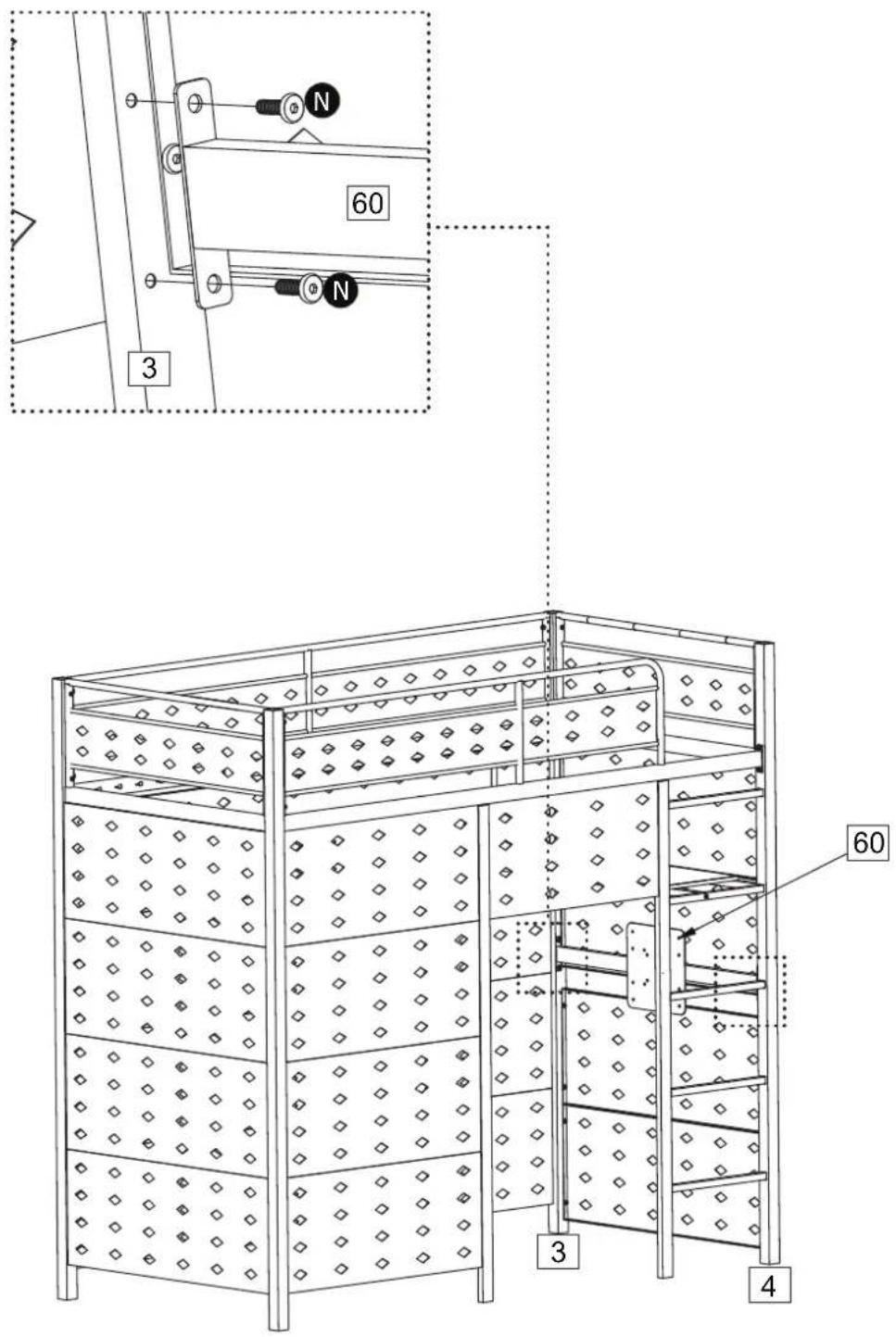
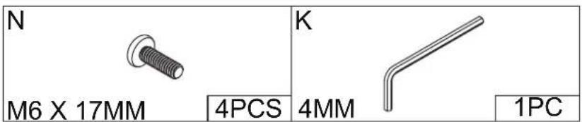
Attach TV Mount 60 to Post 03 3 and Post 04 4 with N.
Note: attach the TV first to the TV mount before you implement this step! It should be a 2 person task for this step to lift and screw the TV/TV mount in place.
Assembly Instructions
Step 17
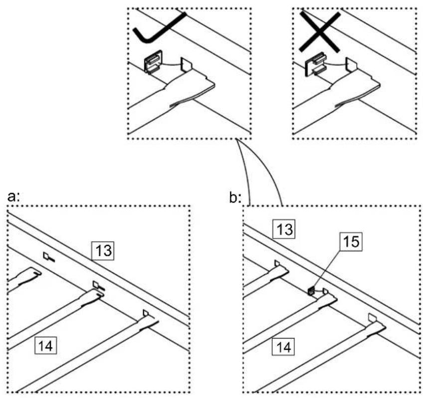
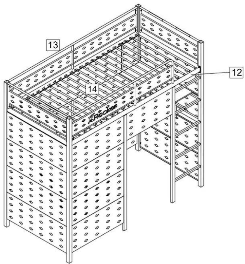
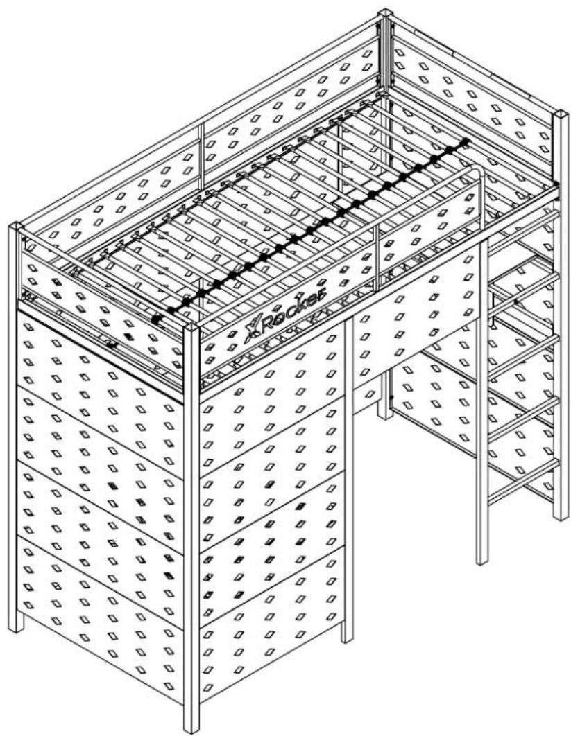
a: Secure the Slats 14 to Rear Guard Rail 13 and Front Guard Rail 12.
b: Secure the Plastic Plug 15 to Rear Guard Rail 13 and Front Guard Rail 12.
Assembly Instructions
Step 18
Assembly Instructions
Step 19
natural_image
Isometric line drawing of a multi-tiered metal shelving unit with perforated panels and a central rack (no text or symbols)Assembly is complete
Note: The TV mount mates with M6 screw. If you're using M4 screw to assemble the TV screen, please use part M washer as provided to make sure M4 screw could be also workable for it.



Brand : X Rocker
Model : Battle Den
Category : Bed