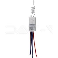
VT-5129 - Smart Home V-TAC - Free user manual and instructions
Find the device manual for free VT-5129 V-TAC in PDF.


| Product Type | Wireless Switch and Receiver Kit |
| Brand | V-TAC |
| Model | VT-5129 |
| Category | Smart Home |
| Switch Power Supply | Button Cell Battery (type not specified) |
| Receiver Power Supply | AC 110-240V, 50/60Hz |
| Maximum Receiver Load | 1000W (LED lamps, incandescent, fans, etc.) |
| Operating Frequency | Radio Frequency (RF), 433 MHz (estimated) |
| Wireless Range | Up to 100 m in open space |
| Number of Switches per Receiver | Up to 8 wireless switches |
| Number of Receivers per Switch | 1 (single group) or 2/3 (multi-group) |
| Switch Dimensions | Approximately 86 x 86 mm (European standard) |
| Receiver Dimensions | Approximately 45 x 45 x 20 mm |
| Switch Weight | Approximately 50 g (with battery) |
| Receiver Weight | Approximately 40 g |
| Material | Durable plastic |
| Protection Rating | IP20 (indoor use) |
| Operating Temperature | -20°C to 45°C |
| Main Functions | Wireless on/off, multiple control, pairing, deletion |
| Maintenance and Cleaning | Clean with a damp cloth, replace battery if necessary |
| Safety | Cut power before installation, installation by an electrician |
| Spare Parts and Repairability | Replaceable button cell battery |
| Warranty | 2 years (excluding normal wear and incorrect installation) |
Frequently Asked Questions - VT-5129 V-TAC
User questions about VT-5129 V-TAC
0 question about this device. Answer the ones you know or ask your own.
Ask a new question about this device
Download the instructions for your Smart Home in PDF format for free! Find your manual VT-5129 - V-TAC and take your electronic device back in hand. On this page are published all the documents necessary for the use of your device. VT-5129 by V-TAC.
USER MANUAL VT-5129 V-TAC
INSTALLATION INSTRUCTION
WIFI RECEIVER
natural_image
Simple geometric diagram with a square frame and a small horizontal line inside (no text or symbols)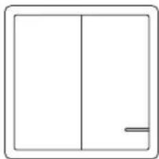
natural_image
Simple line drawing of a two-panel cabinet or panel with a handle (no text or symbols)Wireless Switch
natural_image
Simple line drawing of a rectangular frame with vertical and horizontal lines, no text or symbols present.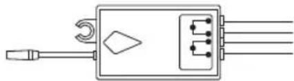
natural_image
Pure electrical circuit lines without any symbolsReceiver
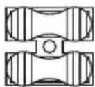
Wire Connector
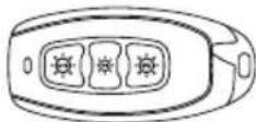
Hand Remote Control

INTRODUCTION & WARRANTY
Thank you for selecting and buying V-TAC Product. V-TAC will serve you the best. Please read these instructions carefully before starting the installation and keep this manual handy for future reference. If you have any other query, please contact our dealer or local vendor from whom you have purchased the product. They are trained and ready to serve you at the best. The warranty is valid for 2 years from the date of purchase. The warranty does not apply to damage caused by incorrect installation or abnormal wear and tear. The company gives no warranty against damage to any surface due to incorrect removal and installation of the product. This product is warranted for manufacturing defects only.
*Note: The product depicted in this manual may appear slightly different from what you receive in the box
MULTI-LANGUAGE MANUAL - QR CODE
Please scan the QR code to access the manual in multiple languages.

INTRODUCTION
Based on radio frequency (RF) and energy harvesting technology, wireless switch does not need external power supply to control. When pressing the button, the mechanical energy automatically converts into electrical energy. Meanwhile the switch will send out radio signals to control the receiver on/off.
WARNING
- Please switch off the power before starting the installation.
- Installation must be performed by a certified electrician/person.
This marking indicates that this product should not be disposed of with other household wastes.

Caution, risk of electric shock.
RECEIVER INSTALLATION
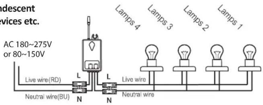
Please follow the below installation diagram to install the receiver.

FIGURE 1
NOTES
A. The integrated load of the wireless receiver is 1000W.
Lamps can be: LED lights, incandescent bulbs, exhaust fans, or WIFI devices etc.
FIGURE 2
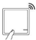
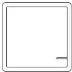
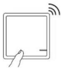
B. A one-gang wireless switch controls a wireless receiver
natural_image
Simple line drawing of a hand pressing a button on a square device with wireless signal waves (no text or symbols)
natural_image
Simple line drawing of an electrical circuit with a light bulb and switch (no text or symbols)FIGURE 3
C. A two-gang wireless switch controls 2 wireless receivers
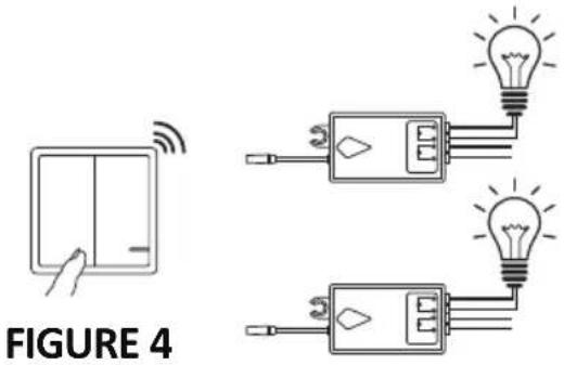
APPLICATION (HOME,HOTEL,INN OR FACTORY ETC.)
D. A receiver can be controlled by 8pcs of wireless switch panels at the most.
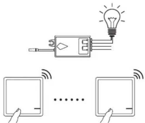
FIGURE 5
E. Three two-gang wireless switch controls 3 wireless receivers

FIGURE 6
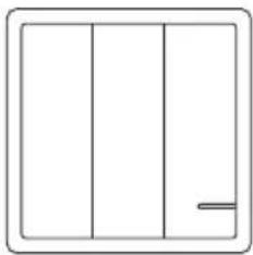
F. A three-gang wireless switch controls 3 wireless receivers
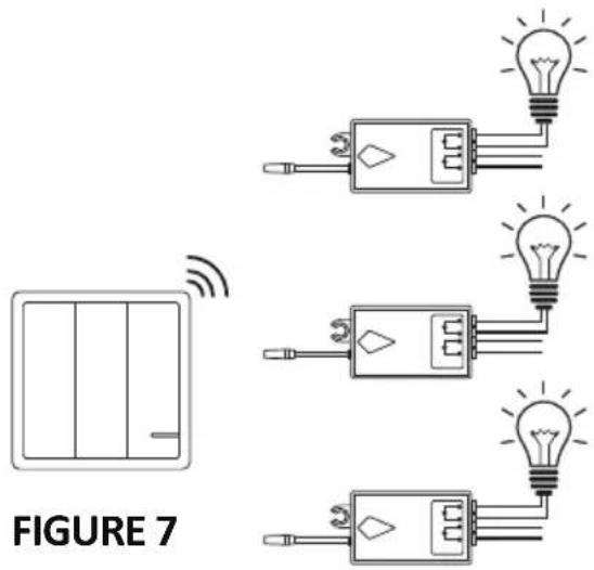
G. A hand remote control switch controls 3 wireless receiver.
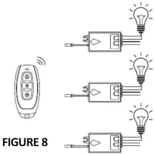
CODE OPERATION
PAIRING THE SWITCH & THE RECEIVER
- Connect the receiver between the light and the power source.
- Power on electricity, press and hold the setting button for 2 seconds. When the indicator light flashes, it enters the matching code mode, then loosen your finger.
- Press the wireless switch button that you want to pair. Use the wireless switch to control the light on or off, indicating that the learning code is successful.
NOTE:
(a) Not recommended that 1 switch controls many receivers.
(b) Ensure that there is no other pairing within 100 mtrs range to avoid interface.
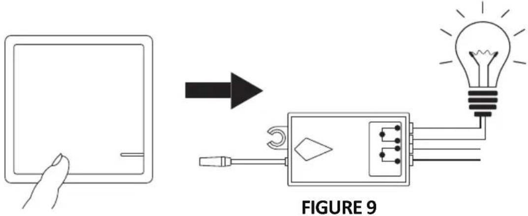
ADDING ANOTHER SWITCH TO A PAIRED SWITCH
Press and hold paired switch panel for about 20s till LED initiator on switch blinks rapidly, then loosen your finger, press the new one, finally test whether it can turn on/off the lamps.
DELETING ADDITIONAL SWITCH FROM A PAIRED SWITCH
Press and hold paired switch panel for about 60s, during which LED indicator on switch changes from: firstly blinks rapidly; secondly blinks 8 times slowly, thirdly blinks 9 times at slower speed, finally blinks once at slowest speed, then loosen
FIGURE 9
UNPAIRING THE RECEIVER
Press and hold the receiver button for about 10s, loosen you finger when indicator light changes from rapid blinks to slower, press the paired switch panel cannot control the lamps
FIGURE 10
HOW TO SET OPEN/CLOSE STATE OF RECEIVER TO MAKE WIRELESS SWITCH COMPATIBLE WITH TRADITIONAL SWITCH
Note: The receiver is default in Close state.
- Power off the electricity, install the receiver as the diagram, and distinguish live from neutral lines.
- Power on the electricity, then program receiver with the switch according to the Learning code Operation chapter
TRADITIONAL SWITCH
FIGURE 11
WIRELESS SWITCH
WIRING DIAGRAM OF ADD WIRELESS SWITCH TO TRADITIONAL SWITCH.
IF THE RECEIVER IS IN OPEN STATE,
- Turn on the traditional switch to light the lamps, the wireless switch can control the lamps.
- Turn off the traditional switch to light the lamps, the wireless switch cannot control the lamps.
METHOD OF SETTING THE RECEIVER IN OPEN STATE
Press and hold switch button for 16s, loosen your finger when the indicator light is continuously bright. (During the 16s, the indicator light will change from quick flash to slower flash, after that, the indicator light will be off, then will be on.)
METHOD OF SETTING THE RECEIVER IN CLOSE STATE
Press and hold switch button for 16s, loosen your finger when the indicator light is continuously bright.
REPLACE THE BATTERY

flowchart
graph LR
    A["Device housing"] --> B["Add device"]
    B --> C["Packaging with grid and buttons"]
    C --> D["Final packaging"]
FIGURE 12
- Remove switch frame and panel with hand or screwdriver.
- Remove 4 screws with screwdriver, take off the battery cover
- Replace the old battery with the new one, pay attention to the positive and negative poles of the battery;
- Install the panel and frame again.
WIRELESS SWITCH INSTALLATION
The switch can be surface mounted with screws or double-sided stickers or set it on the table.
- Install with Double-sided adhesive. (Included)

flowchart
graph LR
    A[" "] --> B[" "] --> C[" "] --> D[" "]
FIGURE 13
Pick up the area where you're going to place the switch, clean the surface with wet rag, post the adhesive rubber in the back of the switch, then attach the switch to the clean surface.
- Install with screws (not included) First, take apart the frame and button panel of the switch, Fix the switch base on the wall with two screws, then install the parts together.

natural_image
Diagram showing a device's internal components and light path, no text or symbols presentFIGURE 14
SPECIFICATIONS
PARAMETERS OF WIRELESS RECEIVER
| Product Size | 39*23*22MM | Working voltage | AC 150~275V or 80~150V |
| Switch times | >400,000 times | Working frequency | 433.932 MHz +/-75KHz |
| Sensitivity -116dB Relay | 10A | ||
| Working current | ≤0.8W | Standby current | ≤0.5W |
| Resistive load | 1800W | Composite load | 1000W (LED) |
| Temperature rise when working | ≤15°C | Fireproof PC | CHIMEI |
| Signal light on the receiver | Red light | Package weight | 32~35g |
PARAMETERS OF THE METAL HAND REMOTE
| Size | 62*30*12MM | Working frequency | 433.932 MHz +/-75KHz |
| Waterproof | IP44 | Quantity of the button | 3 buttons |
| Working voltage | 2~3V(CR2032) | Life of the battery | ≥300,000 times |
| Standby current | ≤0.01 uA | Working temperature | 0~65°C |
| Emission current | ≤25 mA | Storage temperature | -10~85°C |
| Emission Power | ≥+5dbM | Remote distance | ≥160m outdoor≥20m indoor |
PARAMETERS OF THE WIRELESS SWITCH
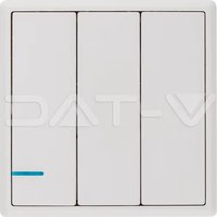
| Product Size | 86*86*11MM86*86*13MM | Type | 1-gang, 2gang,3-gang |
| Switch times | >600,000 times | Working frequency | 433.932 MHz +/-75KHz |
| Sensitivity | -116dB | Working voltage | 3V (CR2032) |
| Package weight 82~86g Life of the battery | ≥300,000 times | ||
| Emission current | ≤30 mA | Standby current | ≤0.01 uA |
| Working temperature | -40~+70°C | Waterproof | IP54 |
| Working characteristics | No need wiring | Fireproof PC | CHIMEI |
| Remote distance | >600m outdoor | Light on the switch | Blue light |
| Remote distance | >40m indoor | Interchangeable panel | The three kinds of panels can be interchangeable |
RECEIVER INSTALLATION
By Screws: Fit the receiver by KA3.5x25 screws on applicable place.
By 3M tapes: Stick the double-side tape on the plain surface of the receiver, then stick the receiver to the applicabe place.
WARNING!
- Please switch off the power before starting the installation.
- Installation must be performed by a certified electrician / person.
Red, Blue input wires connect to AC220V to AC110V power supply. Brown, Blue Output wires connect to lamps.
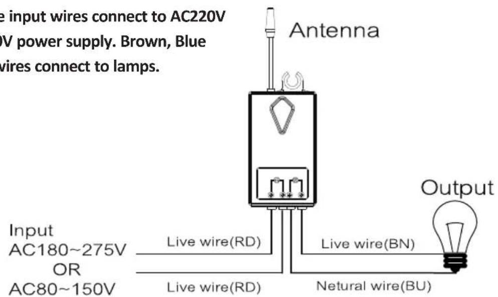
FIGURE 15
CODE LEARNING/PAIRING OR DELETE
flowchart
graph LR
    A["First Pairing"] --> B["First Mode"]
    B --> C["Second Mode"]
    C --> D["Third Mode"]
    D --> E["Light Bulb Connection"]
FIGURE 16
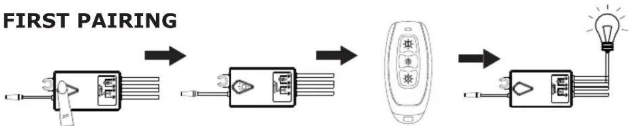
-> Keep pressing the receiver key for 2s
-> LED light is flashing, loosen receiver key and enter the learning mode.
-> Press the remote key which you want to learn code.
-> Lamp turns on. Pairing is successful.
II ADD MORE KEYS
flowchart
graph LR
    A["Remote Control Panel"] --> B["Electric Vehicle Display"]
    B --> C["Electric Vehicle Display"]
    C --> D["Light Bulb Input"]
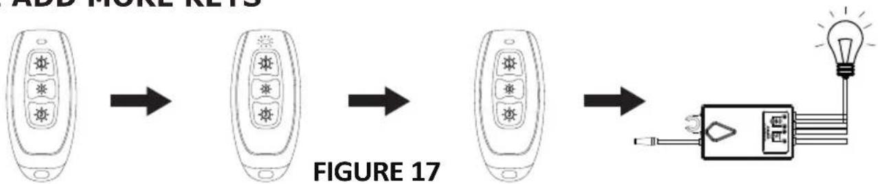
-> Press and hold paired remote key for about 20s till LED inidicator on switch blinks rapidly, then loosen your grip, press the new once. Finally test whether it can turn on/off the lamps.
III DELETE KEYS
flowchart
graph LR
    A["Mobile Phone Icon"] --> B["Mobile Phone Icon"]
    B --> C["Mobile Phone Icon"]
    C --> D["Light Bulb Icon"]
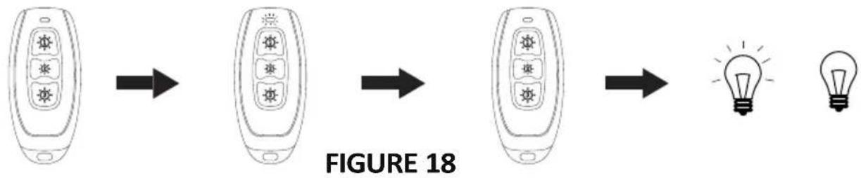
-> Press and hold paired remote key for about 60s, during remote LED indicator on remote changes from:
Firstly blinks rapidly; Secondly blinks 8 times slowly, Thirdly blinks 9 times at slower speed, Finally blinks once at slowest speed, then loosen your grip, press the remote key again to check if you the keys have been deleted or not.
INTRODUCTION & GARANTIE
INTRODUCERE, GARANTIA


- INSTALLATION INSTRUCTION
- WIFI RECEIVER
- INTRODUCTION & WARRANTY
- MULTI-LANGUAGE MANUAL - QR CODE
- INTRODUCTION
- WARNING
- RECEIVER INSTALLATION
- NOTES
- APPLICATION (HOME,HOTEL,INN OR FACTORY ETC.)
- CODE OPERATION
- PAIRING THE SWITCH & THE RECEIVER
- NOTE:
- ADDING ANOTHER SWITCH TO A PAIRED SWITCH
- DELETING ADDITIONAL SWITCH FROM A PAIRED SWITCH
- FIGURE 9
- UNPAIRING THE RECEIVER
- FIGURE 10
- HOW TO SET OPEN/CLOSE STATE OF RECEIVER TO MAKE WIRELESS SWITCH COMPATIBLE WITH TRADITIONAL SWITCH
- FIGURE 11
- IF THE RECEIVER IS IN OPEN STATE,
- METHOD OF SETTING THE RECEIVER IN OPEN STATE
- METHOD OF SETTING THE RECEIVER IN CLOSE STATE
- WIRELESS SWITCH INSTALLATION
- SPECIFICATIONS
- WARNING!
- CODE LEARNING/PAIRING OR DELETE
- INTRODUCTION & GARANTIE
- INTRODUCERE, GARANTIA
Brand : V-TAC
Model : VT-5129
Category : Smart Home