
CAP1512-OF - Drill STANLEY - Free user manual and instructions
Find the device manual for free CAP1512-OF STANLEY in PDF.

| Product Type | Portable Air Compressor |
| Brand | Stanley |
| Model | CAP1512-OF |
| Power Supply | 115 V, 60 Hz, 15 A min |
| Motor | 2 HP / 1.5 HP (running) |
| Operating Pressure | 0 to 150 PSI |
| Air Flow | 3.7 CFM at 40 PSI, 2.8 CFM at 90 PSI |
| Tank Capacity | 1.2 gallons |
| Air Outlet | 1/4 in NPT |
| Pressure Switch | On at 120 PSI, off at 150 PSI |
| Weight | 9.97 kg |
| Safety Devices | Safety valve at 160 PSI, motor thermal protection |
| Maintenance | Daily tank drain, oil-free pump |
| Warranty | 1 year |
| Intended Use | Powering pneumatic tools |
Frequently Asked Questions - CAP1512-OF STANLEY
User questions about CAP1512-OF STANLEY
0 question about this device. Answer the ones you know or ask your own.
Ask a new question about this device
Download the instructions for your Drill in PDF format for free! Find your manual CAP1512-OF - STANLEY and take your electronic device back in hand. On this page are published all the documents necessary for the use of your device. CAP1512-OF by STANLEY.
USER MANUAL CAP1512-OF STANLEY
OPERATIONandMAINTENANCEMANUAL MANUALESDEOPERACIÓNyMANTENIMIENTO LESMANUELSD'UTILISATIONetD'ENTRETIEN
WARNING:
ADVERTENCIA:
ATTENTION:
BEFORE OPERATING THIS TOOL, ALL OPERATORS SHOULD STUDY THIS MANUAL TO UNDERSTAND AND FOLLOW THE SAFETY WARNINGS AND INSTRUCTIONS. KEEP THESE INSTRUCTIONS WITH THE TOOL FOR FUTURE REFERENCE. IF YOU HAVE ANY QUESTIONS, CONTACT YOUR BOSTITCH REPRESENTATIVE OR DISTRIBUTOR.
Congratulations on your purchase of a High Performance BOSTITCH Portable Air Compres This compressor has been designed to provide compressed air to power various pneuma tools - including pneumatic fastening tools.
Before assembling, operating or maintaining this air compressor, users must read and understand the information contained in this owner's manual. Carefully review the Rules Safe Operation section in this owner's manual and fully understand all warnings.
DANGER: Danger indicates an imminently hazardous situation which, if not avoided, WI result in death or serious injury.
⚠WARNING: Warnings indicate a potentially hazardous situation which, if not avoided, could result in death or serious bodily injury.
NOTICE!: Notice indicates important information that if not followed correctly could result damage to equipment.
INDEX
Safety Instructions ....2
Rules for Safe Operation 3,4
Electrical Grounding Instructions 5,6
Specifications 6
Features....7
Operation Instructions....8
General Maintenance....8
Warranty 9
Trouble Shooting guide ....10
Be Educated:
All users must read and fully understand all information contained in this owner's manu before assembling, operating, or maintaining this air compressor.
Avoid Moving Parts:
When the compressor is plugged into an electrical source and the pressure switch is "ON" position, this compressor will cycle automatically.
- Never touch any moving parts.
- Keep all body parts, hair, clothing, and jewelry away from moving parts.
- Never operate the air compressor without all guards and shrouds in place.
- Never stand on the compressor.
Attachments and Accessories:
For any attachment or accessory you will be using with this compressor, the maximum allowable recommended pressure should be clearly marked on the product or should be clearly noted within the operations manual. Exceeding the pressure rating of these attachments (including, but not limited to: air tools, air operated accessories, spray guns, hose, air hose connections, tires and other inflatables) could cause them to fly apart or explode and could result in serious injury.
- Never exceed the maximum allowable pressure recommended by the manufacturer of attachment or accessory you use with this compressor.
Personal Protection:
The employer and/or user must ensure that proper eye protection is worn. Eye protection equipment must conform to the requirements of the American National Standards Institut ANSI Z87.1 and provide both frontal and side protection.
NOTICE!: Non-side shielded spectacles and face shields alone do not provide adequate protection. Eye protection conforming to ANSI Z87.1 will always be marked "Z87".
⚠ WARNING: Additional Safety Protection will be required in some environments. For
example, the working area may include exposure to noise level which can lead to hear damage. The employer and user must ensure that any necessary hearing protection is provided and used by the operator and others in the work area. Some environments will require the use of head protection equipment. When required, the employer and user must ensure that head protection conforming to ANSI Z89.1.
• Always wear eye protection.
- Wear proper hearing and head protection.
- Compressed air blast must never be aimed at anyone. Compressed air can cause body injury and can propel loose particles and small objects at high speed.
- Keep children away from area of operation.
Transporting:
Use the handle to move the compressor. Do not drag or pull the compressor by the p cord or air hose. Always disconnect the air compressor before transporting.
Air Tank:
Due to condensation associated with the process of compressing air, moisture will build inside your compressor's air tank. Drain tank of moisture daily (See General Maintenance Failure to drain moisture from the tank properly could lead to the formation of rust and thinning of the steel tank.
⚠WARNING: FAILURE TO REGULARLY DRAIN TANK MAY CAUSE TANK CORROSION AND RISK OF TANK EXPLOSION, RESULTING IN SERIOUS INJURY. TO AVOID RISK OF TANK FAILURE DURING USE, DRAIN TANK AFTER EACH USE OR EVERY FOUR HOURS OF OPERATION TO PREVENT CONDENSATION BUILD-UP AND TANK CORROSION.
⚠ WARNING: DO NOT PERFORM WELDING OR REPAIR OPERATIONS ON THE AIR TANK OF THIS COMPRESSOR. WELDING ON THE AIR COMPRESSOR TANK CAN SEVERELY IMPAIR TANK STRENGTH AND CAUSE AN EXTREMELY HAZARDOUS CONDITION. WELDING ON THE TANK IN ANY MANNER WILL VOID THE WARRANTY.
Ventilation:
⚠️WARNING: RISK OF FIRE OR EXPLOSION - DO NOT SPRAY FLAMMABLE LIQUID IN A CONFINED AREA. SPRAY AREA MUST BE WELL VENTILATED. DO NOT SMOKE WHILE SPRAYING AND DO NOT SPRAY WHERE SPARK OR FLAME IS PRESENT. KEEP COMPRESSORS AS FAR FROM SPRAYING AREA AS POSSIBLE.
Risk of Burns:
All air compressors generate heat, even operating under normal conditions. Bostitch compressors have been designed to reduce the risk of burns by limiting access to tube cylinder head parts. In areas where tubes are exposed, a protective sheathing has been added to the tubes to reduce risk; however, risk of burns does exist.
- To avoid serious burns, never touch the cylinder head parts or tubing during or imme after operation.
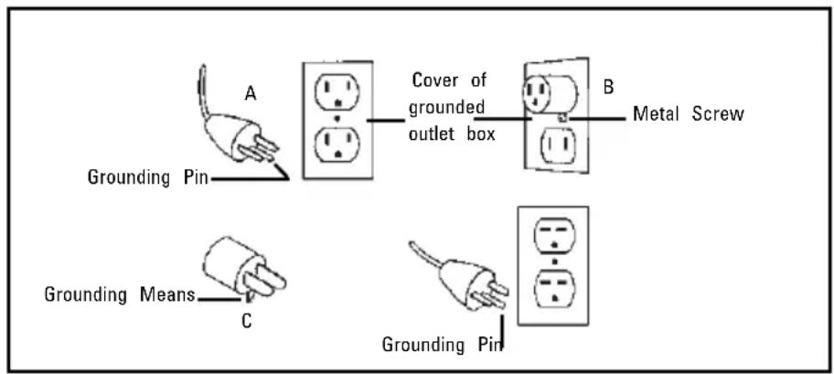
This product should be electrically grounded. In the event of an electrical short circuit, grounding reduces the risk of electrical shock by providing an escape wire for electrica current. This product is equipped with a cord having a grounding wire with an appropri grounding plug. The plug must be plugged into an outlet that is properly installed and grounded in accordance with all local codes and ordinances.
DANGER: IMPROPER INSTALLATION OF THE GROUNDING PLUG CAN RESULT IN A RISK
OF ELECTRIC SHOCK. If a repair or replacement cord is necessary, do not connect the grounding wire to either flat blade terminal. Check with a qualified electrician or service if the grounding instructions are not completely understood or if there is doubt as to w this product is properly grounded. Do not modify the plug provided. If the supplied plug not fit the outlet, have the proper outlet installed by a qualified electrician.
This product is shipped for use on a nominal 120-volt circuit, and has a grounding plug looks like the plug in sketch A. A temporary adapter that looks like the adapter illustrates sketches B and C may be used to connect this plug to a 2-pole receptacle as shown B, if a properly grounded outlet is not available. The temporary adapter should be used until a properly grounded outlet (sketch A) can be installed by a qualified electrician. The green colored rigid ear, lug, or like extending from the adapter must be connected to a permanent ground such as a properly grounded outlet box cover. Whenever the adapter used, it must be held in place by a metal screw.
The motor of this compressor has a thermal overload protector in the motor winding. If motor should overheat, the overload protector will shut the motor off. When the temperature returns to normal, the motor will restart automatically.
NOTICE! Do not stop the compressor by pulling out the plug. Use only the On/Off switc which operates a pressure relief valve on the compressor. If the compressor is plugged with the switch in the "On" position, the compressor may have trouble restarting agains high pressure which could cause excessive heat build up and could damage the motor.
Safety Valve:
This compressor is equipped with a safety valve that is set to avoid over-pressurization air tanks. This valve is factory pre-set at 160 PSI and will not function unless tank pre reaches this pressure.
⚠ WARNING: DO NOT ATTEMPT TO ADJUST OR ELIMINATE THIS SAFETY DEVICE. ANY ADJUSTMENTS TO THIS VALVE COULD CAUSE SERIOUS INJURY. If this device requires service or maintenance, see an Authorized BOSTITCH Service Center.
DUTY CYCLE:
To ensure long life of your BOSTITCH air compressor, do not operate on more than a cycle. If this air compressor pumps air more than 50% of one hour, then the compress capability is less than the air delivery required by the application. Always match the air volume requirements of the attachment or accessory with the air volume delivery of the compressor.
Notice!: BOSTITCH does not recommend the use of extension cords with compressors. I use of an extension cord can result in the loss of voltage supplied to the compressor could prevent the compressor from starting. For optimum performance, plug the compressor directly into an outlet and increase the length of airline as needed.
If an extension cord must be used, use these guidelines:
Distance Needed Recommended Gauge
Less than 25 ft. 12 Gauge
25 - 50 ft. 10 Gauge
Greater than 50 ft. Not Recommended
CAP1512-OF SPECIFICATIONS
Motor: 2HP (Peak) / 1.5HP (Running)
115V - 60HZ
Fuse Requirements: 15 Amps minimum
Operating Pressure: 0 - 150PSI
Safety Valve Setting: 160 PSI
Air Delivery: 3.7 CFM @ 40 PSI
2.8 CFM @ 90 PSI
Maximum Amps at Working Pressure: 12
Tank Size:
1.2 Gallons
Air Outlet:
1/4" NPT
Pressure Switch Settings:
On @ 120 PSI
Weight:
Off @ 150 PSI
PSI = Pounds Per Square Inch:
22lbs.
CFM = Cubic Feet Per Minute
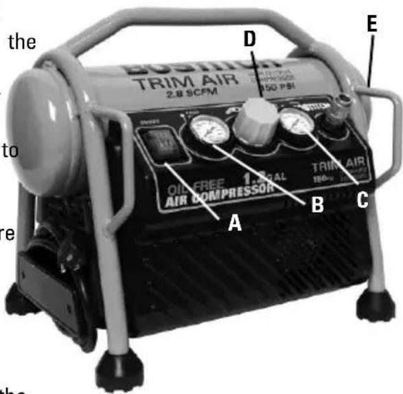
A. Pressure Switch: - The pressure switch is the activation mechanism that is used to start and stop the compressor. When the switch is "On", the motor and pump will compress air until tank pressure reaches the upper limit of the factory set operating pressure. When tank pressure falls below the factory set "cut in" pressure, the compressor will again automatically start to compress air.
B. Tank Pressure Gauge: The tank pressure gauge indicates the air pressure that is present in the tank in PSI (lbs/sq. in.).
C. Regulated Pressure Gauge: The regulated pressure gauge indicates the amount of pressure that is allowed into the discharge line according to the setting of the regulator.
D. Regulator Knob: The regulator knob is used to adjust the air pressure that is available the discharge line. The discharge air pressure is increased by turning the knob clockwise and decreased by turning the knob counter clockwise.
E. Drain Valve: Ball style valve that drains moisture from the tank when opened.
Pre-Start Procedures:
- Inspect the compressor for any damaged components. Do not operate if compressor damaged.
- Verify that the tanks have been drained and are clear of any moisture or dirt (See "Draining Tank").
Start-Up Procedures:
- Verify that the On/Off switch is in the Off position.
- Verify that the tank air pressure is at 0 PSI.
- Attach the air hose to the discharge line.
- Plug the unit into a properly grounded outlet.
- Push the On/Off switch to On. The On/Off switch will light-up to indicate the compre on. The compressor will automatically cycle on and off to keep the tank pressure maintained.
- Adjust the pressure regulator to the proper pressure setting required for the air tool.
Shut-Off Procedures:
- Push in the On/Off switch to the Off position.
GENERAL MAINTENANCE
Service and Maintenance:
Prior to performing service and maintenance to the compressor, always disconnect all accessories and attachments from the unit, and disconnect the compressor from the electrical source and drain tank. When replacing parts, only use Genuine BOSTITCH replacement parts.
Notice!: This compressor is equipped with an oil-free pump. There is no oil to replace check.
Draining Tank - Ball-Style Drain Valves:
- Verify that the compressor is turned "Off".
- Holding the handle, tilt the compressor toward the drain valve so it is positioned at the bottom of the tank.
- Turn the drain valve to open.
- Keep the compressor tilted until all moisture has been removed.
ANY OTHER SERVICE SHOULD ONLY BE PERFORMED BY AN AUTHORIZED BOSTITCH SERVICE CENTER
Stanley Fastening Systems L.P. ("Bostitch") warrants to the original retail purchaser that this product is free from defects in material and workmanship, and agrees to repair or replace, at Bostitch's option, any defective product within 1 year from the date of purchase. This warranty is not transferable. It only covers damage resulting from defects in material or workmanship, and it does not cover conditions or malfunctions resulting from normal wear, neglect, abuse, accident or repair attempted or made by other than our regional repair center or authorized warranty service center.
THIS WARRANTY IS IN LIEU OF ALL OTHER EXPRESS WARRANTIES. ANY WARRANTY OF MERCHANTABILITY OR FITNESS FOR A PARTICULAR PURPOSE IS LIMITED TO THE DURATION OF WARRANTY. BOSTITCH SHALL NOT BE LIABLE FOR ANY INCIDENTAL OR CONSEQUENTIAL DAMAGE
This warranty is limited to sales in the United States and Canada. Some states do not allow limit on how long an implied warranty lasts, or the exclusion or limitation of incidental or consequential damages, so the above limitations or exclusions may not apply to you. This warranty gives you specific legal rights, and you may also have other rights which vary from state to state.
To obtain warranty service, return the product at your expense together with proof of purchase to Bostitch Regional or authorized warranty repair center. You may call us at 1-800-556-6696 for the location of authorized warranty service centers in your area.
TROUBLE SHOOTING GUIDE
NOTE: REMOVE POWER SOURCE AND DRAIN TANK PRESSURE PRIOR TO MAKING ANY REPAIRS OR ADJUSTMENTS.
Problem Probable Cause Correction
Unit will not run Tank pressure exceeds "cut in" pressure Once pressure drops below "cut in" pressure, the unit will start.
Extension cord causing excessive amp draw Check guidelines for proper cord gauge (use of extension cords is not recommended).
Fuse or circuit tripped Replace fuse or reset breaker
Unit not turned on or not plugged in Check pressure switch and verify that it is in the On position. Verify that unit is plugged in.
Cold weather conditions Place compressor in warmer environment for at least 30 minutes (typically temperatures below freezing) then try restarting.
Tighten fitting. Check with soapy water. DO NOT OVER TIGHTEN.
Application requires excessive air demand Reduce demand on compressor
Tighten bolts on head
Remove head and check for broken or deformed gasket. Replace if needed. Close drain valve
Remove head and replace valves.
Fittings loose
Application requires excessive air demand
Loose head
Blown gasket
Open drain valve Wom or broken valv
Damaged air tank
Unit will not build pressure
Air leak at tank or air tank welds.
WARNING:
DAMAGED OR MODIFIED TANKS CAN RUPTURE. REPLACE TANK IMMEDIATELY.
INTRODUCCIÓN


- OPERATIONandMAINTENANCEMANUAL MANUALESDEOPERACIÓNyMANTENIMIENTO LESMANUELSD'UTILISATIONetD'ENTRETIEN
- WARNING:
- ADVERTENCIA:
- ATTENTION:
- INDEX
- Be Educated:
- Avoid Moving Parts:
- Attachments and Accessories:
- Personal Protection:
- Transporting:
- Air Tank:
- Ventilation:
- Risk of Burns:
- DANGER: IMPROPER INSTALLATION OF THE GROUNDING PLUG CAN RESULT IN A RISK
- Safety Valve:
- DUTY CYCLE:
- CAP1512-OF SPECIFICATIONS
- Pre-Start Procedures:
- Start-Up Procedures:
- Shut-Off Procedures:
- GENERAL MAINTENANCE
- Service and Maintenance:
- Draining Tank - Ball-Style Drain Valves:
- ANY OTHER SERVICE SHOULD ONLY BE PERFORMED BY AN AUTHORIZED BOSTITCH SERVICE CENTER
- TROUBLE SHOOTING GUIDE
- NOTE: REMOVE POWER SOURCE AND DRAIN TANK PRESSURE PRIOR TO MAKING ANY REPAIRS OR ADJUSTMENTS.
- Problem Probable Cause Correction
- INTRODUCCIÓN
Brand : STANLEY
Model : CAP1512-OF
Category : Drill