AN-WL100E - TV Accessories LG - Free user manual and instructions
Find the device manual for free AN-WL100E LG in PDF.
| Product Type | Wireless Media Box + Wireless Dongle |
| Brand | LG |
| Model | AN-WL100E |
| Dimensions (W x H x D) - Box | 326.0 x 42.8 x 226.0 mm |
| Weight - Box | 1.5 kg |
| Dimensions (W x H x D) - Dongle | 148.0 x 23.0 x 78.0 mm |
| Weight - Dongle | 0.2 kg |
| Power Supply - Box | DC 12 V, 1.1 A |
| AC Adapter | Input AC 100-240 V ~ 50/60 Hz, Output DC 12 V, 2.5 A |
| Wireless Frequency Band | 5 GHz (U-NII-1 to U-NII-3) |
| Maximum Wireless Range | 15 m (line of sight, without interference) |
| Video Inputs | HDMI (x4), Component (Y Pb Pr), RGB (PC), SCART (AV1), RCA (AV2) |
| Audio Inputs | Audio L/R for Component, PC Audio (RGB/DVI), RCA Audio |
| Audio Output | Optical Digital (S/PDIF) |
| TV Connectivity | Wireless Dongle with 20-pin cable (power/control) + HDMI cable |
| Device Control | IR Blaster for remote control |
| Operating Temperature | 0 °C to 40 °C |
| Operating Humidity | Less than 80% |
| Compatibility | LG TVs compatible with Wireless Ready (LCD, LED, Plasma) |
| Accessories Included | 12V adapter, HDMI cable, 20-pin cable, IR blaster, Velcro strip, cable tie, management clip, polishing cloth, manual |
| Intended Use | Household use only, indoor |
Frequently Asked Questions - AN-WL100E LG
User questions about AN-WL100E LG
0 question about this device. Answer the ones you know or ask your own.
Ask a new question about this device
Download the instructions for your TV Accessories in PDF format for free! Find your manual AN-WL100E - LG and take your electronic device back in hand. On this page are published all the documents necessary for the use of your device. AN-WL100E by LG.
USER MANUAL AN-WL100E LG
Please read this manual carefully before operating your set and retain it for future reference.
PREPARATION
Accessories 3
Front panel controls 4
BACK PANEL INFORMATION 5
Side panel INFORMATION 5
Wireless Ready Dongle 6
Connecting to the TV 6
Attaching the Wireless Ready Dongle. 7
Back Cover for Wire Arrangement. 8
Connection of 12 V AC/DC Adapter.8
Optimal Installation Location of Wireless Media Box 9
Reception Problems due to Interference. 9
Attaching the IR blaster. 10
Optimal location of external device with IR Blaster installed 10
EXTERNAL EQUIPMENT SETUP
Connecting with a Component cable. 11
Connecting with an HDMI cable 12
Connecting with an HDMI to DVI cable............13
Connecting with a Euro Scart cable 14
Connecting with RCA cable 15
Digital Audio Out Setup. 16
Connecting with RGB. 16
Supported Display Resolution. 17
WATCHING TV / PROGRAM CONTROL
Turning on the Wireless Media box 18
Input list 20
IR Blaster Setup 20
APPENDIX
IR Code List 21
RF Specifications 22
Frequency Table. 23
Product Specifications. 24
Troubleshooting 24
Open Source Software Notice 26
Indoor use only
This device only works with compatible Wireless
Ready LG LCD, LED LCD, and Plasma TVs.
This product does not support 3D.
DOLBY
DIGITAL
Manufactured under license from Dolby Laboratories.
Dolby and the double-D symbol are trademarks of
Dolby Laboratories.
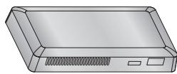
PREPARATION
ACCESSIONS
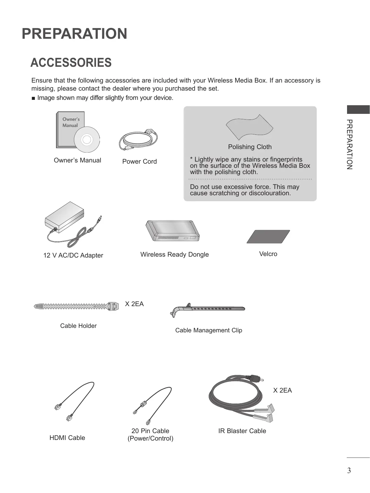
Ensure that the following accessories are included with your Wireless Media Box. If an accessory is missing, please contact the dealer where you purchased the set.
Image shown may differ slightly from your device.

Owner's Manual
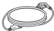
Power Cord

Polishing Cloth
- Lightly wipe any stains or fingerprints on the surface of the Wireless Media Box with the polishing cloth.
Do not use excessive force. This may cause scratching or discolouration.
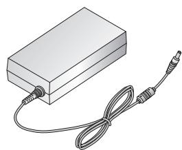
12 V AC/DC Adapter
Wireless Ready Dongle

Velcro
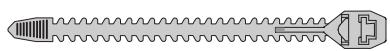
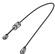
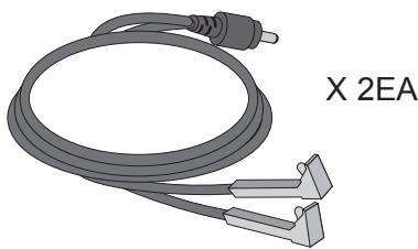
Cable Holder
X 2EA
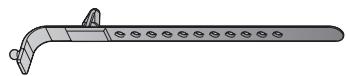
Cable Management Clip
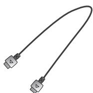
HDMI Cable
20 Pin Cable (Power/Control)
IR Blaster Cable
FRONT PANEL CONTROLS
NOTE
This product is only for home use.
- Do not use this product in medical institutions or near medical devices. It may cause some medical devices to malfunction.
Wireless device used to this instrument could be set up and used only to this instrument.
- When using the external device connected to the Wireless Media Box, some functions of the TV menu may not work.
- Image shown may differ slightly from your device.
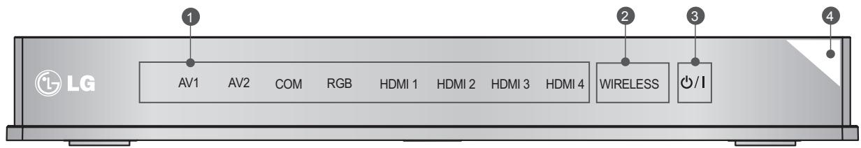
Input Source Indicator & INPUT touch button
Select the input source by touching.
Wireless Connection Indicator
It will flash when trying to connect to a wireless network and be turned on when connected.
③ POWER touch button
Turn the Wireless Media Box on or off by touching.
If the / (Power) button of the Wireless Media Box is not turned on, the
Wireless Media Box will not be turned on even when turn on the power of the TV.
If the Wireless Media Box is not turned on even after turning the power of the TV on, check the / (Power) button of the Wireless Media Box.
Power/Standby Indicator
Illuminates red in standby mode.
Illuminates white when the Wireless Media Box is switched on.
- ID Label of Wireless Media Box is located at the bottom of Wireless Media Box.
BACK PANEL INFORMATION
Image shown may differ slightly from your device.
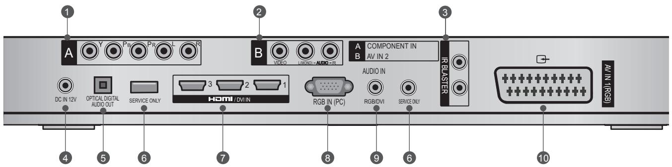
Component Input
Connect a component video/audio device to this jack.
Audio/Video Input (AV IN 2)
Connect audio/video output from an external device to these jacks.
IR Blaster
Controls external equipment.
DC IN 12 V Power Cord Socket
This Wireless Media Box operates on 12 V DC power. Only use a power converter that the device was designed to use.
Optical Digital Audio Out
Optical digital audio output for use with amps. Note: In standby mode, this port doesn't work.
SIDE PANEL INFORMATION
Image shown may differ slightly from your device.
SERVICE ONLY PORT
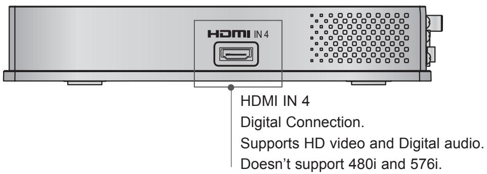
HDMI/DVI IN Input
Digital Connection. Supports HD video and Digital audio. Doesn't support 480i. Accepts DVI video using an adapter or HDMI to DVI cable (not included).
RGB IN (PC) Input
Analog PC Connection. Uses a D-sub 15 pin cable (VGA cable).
9 AUDIO IN (RGB/DVI) Input
Connect the audio from an external device.
10 Euro Scart Socket (AV IN 1)
Connect scart socket input from an external device to these jackets.
Image shown may differ slightly from your device.
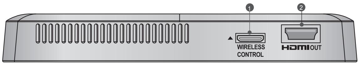
Wireless Control Port
This port is used to send and receive commands between the TV and the Wireless Media Box.
HDMI Out Port
This port sends the audio and video received from the Wireless Media Box to the TV.
CONNECTING TO THE TV
Image shown may differ slightly from your device.
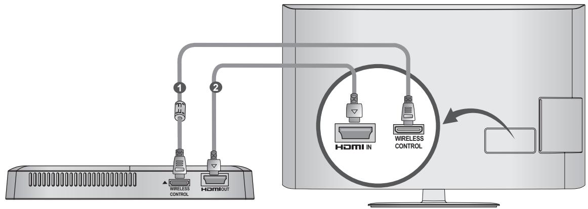
Use the provided 20 pin cable (power/control) to connect to the wireless control port of the Wireless Ready Dongle and the wireless control port on the TV.
Now connect the HDMI to both the TV and the Wireless Ready Dongle.
NOTE
Install the Wireless Ready Dongle with the power of the TV turned off.
- Use the wireless control jack and 20 pin cable only for connecting the Wireless Ready TV and Wireless Ready Dongle. When used for other purposes, it can cause an error or damage to the product.
ATTACHING THE WIRELESS READY DONGLE
The Wireless Ready Dongle can be attached to the back of the TV with the included materials.

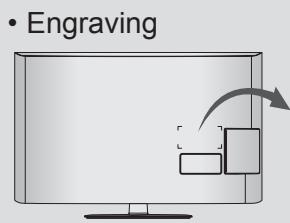
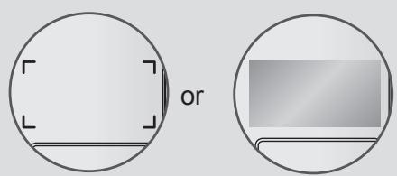
Remove the protective paper from the included Velcro pad and attach it to the TV as shown. It does not have to be in same position, but should be close to the TV's inputs. The TV will have a recommended location engraved on the TV.
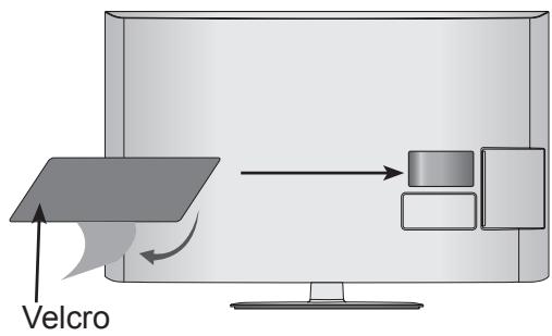

Now place the Wireless Ready Dongle onto the Velcro pad.
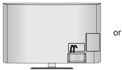
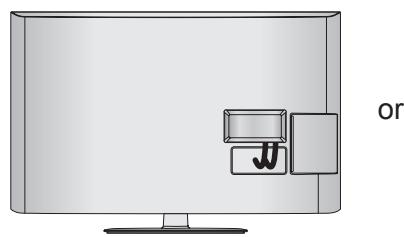

NOTE
The attaching location on the Wireless Ready Dongle can differ by model. Check the engraving on the back cover and attach the cable according to the engraving.
Clean the part where the magic tape (Velcro) is attached using the supplied brush and attach the part by pressing the area evenly for 1 minute. After about 10 minutes attach the wireless dongle firmly.
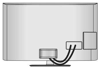
BACK COVER FOR WIRE ARRANGEMENT
Image shown may differ slightly from your device.
1 Connect the cables as necessary. (Refer to the p.6 to 7.)
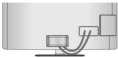
After connecting the cables, bundle the cables and install the Cable Holder as shown.
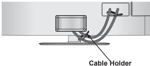
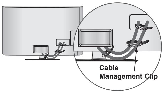
Now install the Cable Management Clip which will attach to the back of the TV. NOTE: The Cable Management Clip attachment location on the TV can differ by model.
NOTE
Do not use the Cable Management Clip to lift the TV. If the TV is dropped, you may be injured or the TV may be damaged.
CONNECTION OF 12 V AC/ DC ADAPTER
Image shown may differ slightly from your device.
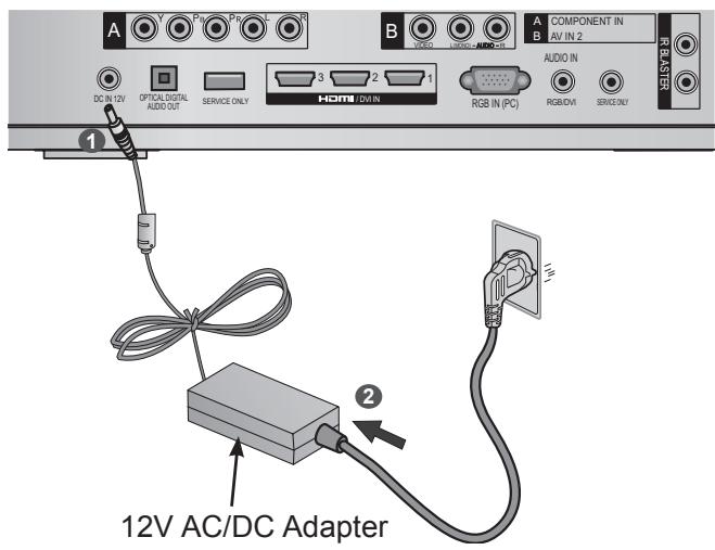
Connect the 12 V AC/DC adapter plug to the DC IN 12V input jack on the Wireless Media Box.
Connect the power cord to the 12 V AC/DC adapter first, then plug the power cord into the wall power outlet.
CAUTION
Please be sure to connect the Wireless Media Box to the AC/DC power adapter before connecting the power plug of the Wireless Media Box to a wall power outlet.
OPTIMAL INSTALLATION LOCATION OF WIRELESS MEDIA BOX
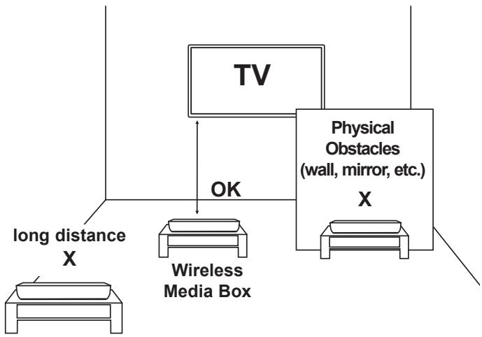
The nearer the distance between Wireless Media Box and TV, the better the wireless function.
We recommend that you place the Media Box and the TV in the same room.
- The more objects that are in between the Media Box and the TV, the more the reception strength decreases.
If the heat from certain objects (e.g., a heater or a radiator) can reach and warm the Media Box, this may also cause transmission quality to suffer.

- When you press the OK button while viewing the external input of Wireless Media Box, the information of the current input and the strength of the wireless signal will be displayed on the bottom left side.


Good Reception
Adjust the location and directio of the Wireless Media Box until you get good reception.
RECEPTION PROBLEMS DUE TO INTERFERENCE
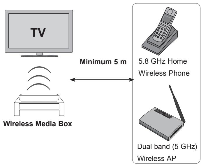
Wireless units of 5 GHz Band
-
Problems such as a connection delay, audio cut-off, and poor picture quality may occur due to interference if there are several wireless devices with a 5 GHz band (5.15 GHz to 5.85 GHz) operating in the same home or in close proximity to each other. If these problems occur, take the following actions:
-
Maintain a distance of at least 5m between the TV and another device with a 5 GHz band.
- Position the Media Box in a location closer to the TV.
- Place the Media Box in a higher position. (a minimum of 1 m is recommended.)
-
Please set your wireless LAN to 2.4 GHz Band (channel 1 to 11).
-
Please refer the manual of your router for detail information.
- If it is not possible to change the channel, please move the router away from the wireless ready dongle.
ATTACHING THE IR BLASTER
The IR blaster allows the LG TV to control external equipment, like a cable box.
1 Connect the provided IR Blaster cable to the IR Blaster terminal on the Wireless Media Box.
After removing the protection paper from the IR Blaster cable, adhere it to the external equipment as shown.
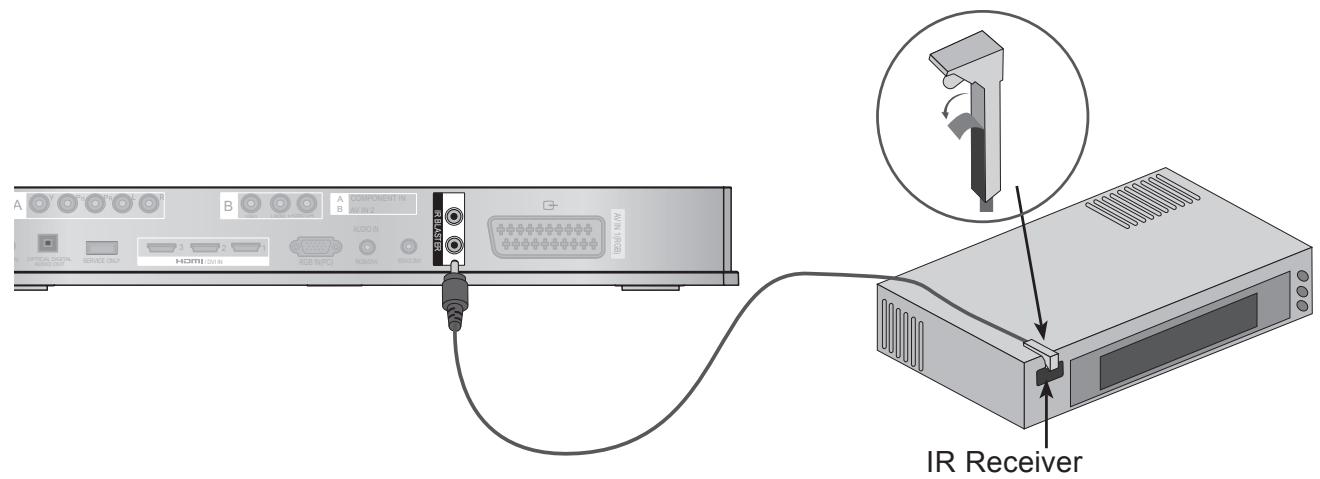
NOTE
- When you attach the IR Blaster sensor near the remote control sensor of the external device, the signal can be detected more efficiently.
OPTIMAL LOCATION OF EXTERNAL DEVICE WITH IR BLASTER INSTALLED
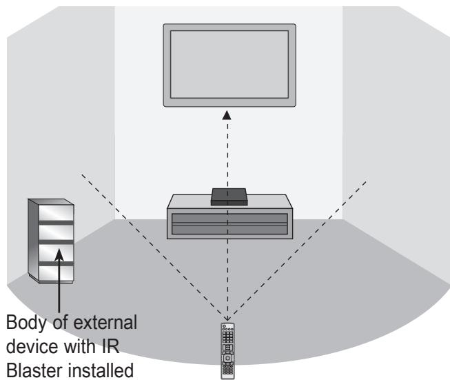
Install the external device with the IR Blaster installed at a location it is not affected by the signal from the remote controller to the TV. When the external device with the IR Blaster installed receives the signal from the remote controller simultaneously with the TV, it may not operate.
NOTE
For some external devices, the IR Blaster may not operate depending on the performance of the IR receiver.
The operation may be delayed due to the sensitivity of the wireless signal.
EXTERNAL EQUIPMENT SETUP
- To avoid damaging any equipment, never plug in any power cord until you have finished connecting all equipment.
Image shown may differ slightly from your device.
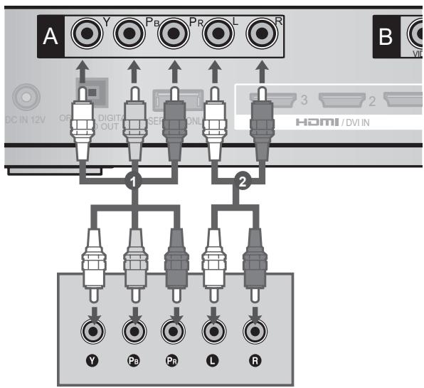
CONNECTING WITH A COMPONENT CABLE

Connect the video outputs (Y, PB, PR) of the external equipment (digital set-top box, DVD, etc.) to the COMPONENT IN VIDEO jacks labeled A on the Wireless Media Box.

Connect the audio output of the external equipment (digital set-top box, DVD, etc.) to the COMPONENT IN AUDIO jacks on the Wireless Media Box.

Turn on the external equipment. (Refer to the external equipment's manual for operating instructions.)

Select the Wireless Component input source using the INPUT button on the remote control of TV. Refer to the user manual of the connected TV for the format of component input.
Component Input ports
To achieve better picture quality, connect a DVD player to the component input ports as shown below.
| Component ports on the Wireless Media Box | Y | PB | PR |
| Video output ports on DVD player | Y | PB | PR |
| Y | B-Y | R-Y | |
| Y | Cb | Cr | |
| Y | Pb | Pr |
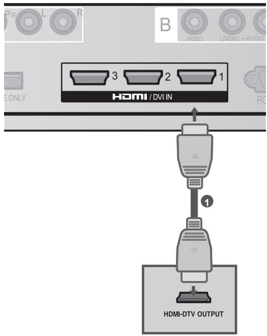
CONNECTING WITH AN HDMI CABLE

Connect the HDMI output of the external equipment (digital set-top box, DVD, etc.) to HDMI/DVI IN 1, HDMI/DVI IN 2, HDMI/DVI IN 3 or HDMI IN 4 jack on the Wireless Media Box.

Turn on the external equipment.

Select Wireless HDMI1, Wireless HDMI2,
Wireless HDMI3 or Wireless HDMI4 input source using the INPUT button on the remote control of TV.
Refer to the user manual of the connected TV for the format of HDMI input..
NOTE
The Wireless Media Box can receive video and audio signals simultaneously when using an HDMI cable.
If the DVD does not support Auto HDMI, you must set the output resolution appropriately.
- Check that your HDMI cable is High Speed HDMI Cable. If the HDMI cables are not High Speed HDMI Cable, flickering or no screen display can result. Please use the High Speed HDMI Cable.
HDMI Audio Supported format : Dolby Digital, PCM. DTS Audio format is not supported.
CONNECTING WITH AN HDMI TO DVI CABLE
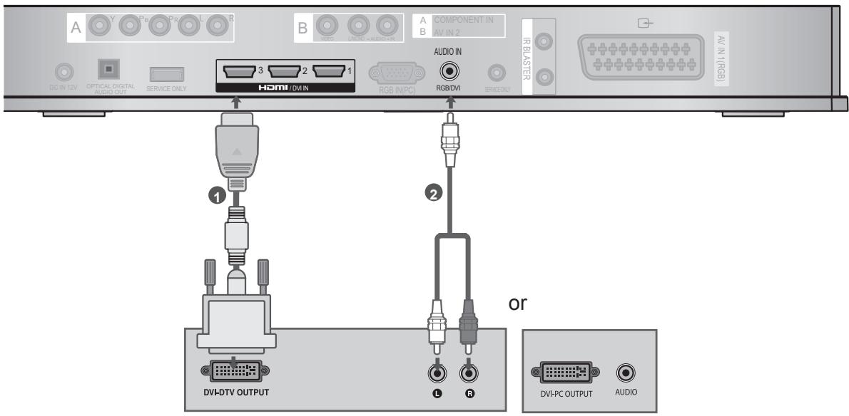
1 Connect the digital set-top box or the DVI output of the PC to HDMI/DVI IN 1, HDMI/DVI IN 2 or HDMI/DVI IN 3 jack on the Wireless Media Box.
Connect the audio output of the digital set-top box or the PC audio output to the AUDIO IN (RGB/DVI) jack on the Wireless Media Box.
Turn on the digital set-top box or the PC and the Wireless Media Box. (Refer to the digital set-top box or the PC manual for operating instructions.)
4 Select Wireless HDMI1, Wireless HDMI2 or Wireless HDMI3 input source using the INPUT button on the remote control of TV.
CONNECTING WITH A EURO SCART CABLE
1 Connect the Euro scart socket of the external equipment (DVD, VCR, etc.) to the AV1 Euro scart socket on the Wireless Media Box.
Turn on the external equipment. (Refer to the external equipment's manual for operating instructions.)
3 Select AV1 input source using the INPUT button on the remote control of TV.
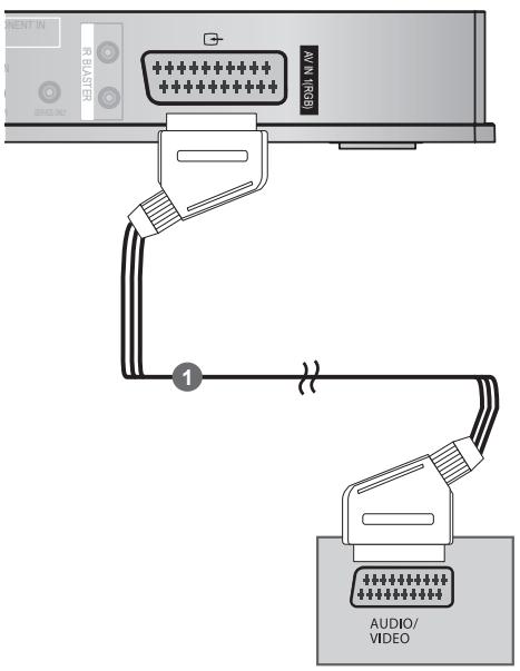
| Scart | Input | Output | ||
| Video | Audio | RGB | ||
| AV1 | O | O | O | X |
NOTE
Any Euro scart cable used must be signal shielded.
CONNECTING WITH RCA CABLE
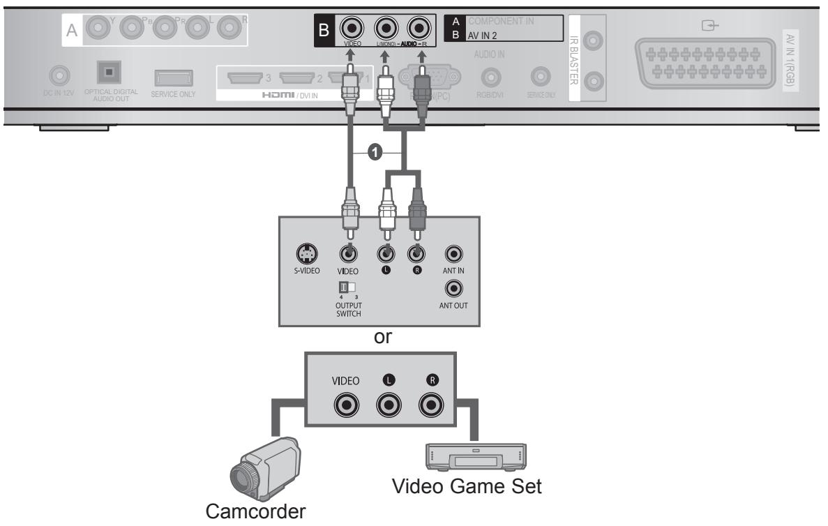
1 Connect the AUDIO/VIDEO jacks between Wireless Media Box and VCR or external equipment.
2 Insert a video tape into the VCR and press PLAY on the VCR. (Refer to the VCR owner's manual.)
Or, Operate the corresponding external equipment.
(Refer to external equipment operating guide.)
3 Select Wireless AV2 input source using the INPUT button on the remote control of TV.
NOTE
If you have a mono VCR, connect the audio cable from the VCR to the AUDIO L/MONO jack of the media box.
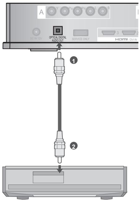
DIGITAL AUDIO OUT SETUP
You can output the Wireless Media Box's audio signal to external audio equipment via the Optical Digital Audio Output port. This port uses a standard optical cable.

Connect one end of an optical cable to the OPTICAL DIGITAL AUDIO OUT port on the Wireless Media Box.

Connect the other end of the optical cable to the digital audio (Optical) input on the audio equipment.

CAUTION
- Do not look into the optical output port. Looking at the laser beam may damage your vision.
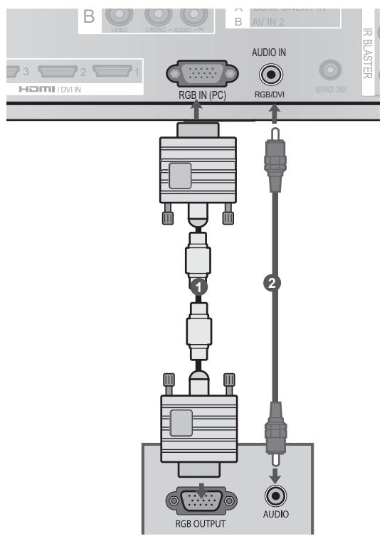
CONNECTING WITH RGB
You can also connect devices using the RGB input. This connection uses a standard VGA cable (D-Sub 15 pin cable). This Wireless Media Box supports Plug and Play capability, meaning that the PC adjusts automatically to the Wireless Media Box's settings.

Connect the RGB output of the PC to the RGB IN (PC) jack on the Wireless Media Box.

Connect the PC audio output to the AUDIO IN (RGB/DVI) jack on the Wireless Media Box.

Turn on the PC and the Wireless Media Box.

Select Wireless RGB input source using the INPUT button on the remote control of TV.
SUPPORTED DISPLAY RESOLUTION
RGB-PC, HDMI/DVI-PC mode
| Resolution | Horizontal Frequency(kHz) | Vertical Frequency(Hz) |
| 720x400 | 31.468 | 70.08 |
| 640x480 | 31.469 | 59.94 |
| 800x600 | 37.879 | 60.31 |
| 1024x768 | 48.363 | 60.00 |
| 1280x768 | 47.78 | 59.87 |
| 1360x768 | 47.72 | 59.80 |
| 1280x1024 | 63.981 | 60.02 |
| 1920x1080 (RGB-PC) | 66.587 | 59.93 |
| 1920x1080 (HDMI-PC) | 67.5 | 60.00 |
NOTE
- There may be interference relating to resolution, vertical pattern, contrast or brightness in PC mode. Change the PC mode to another resolution or change the refresh rate to another rate or adjust the brightness and contrast on the menu until the picture is clear. If the refresh rate of the PC graphic card can not be changed, change the PC graphic card or consult the manufacturer of the PC graphic card.
The synchronization input waveform for Horizontal and Vertical frequencies are separate. -
Connect the signal cable from the monitor output port of the PC to the RGB (PC) port of the Wireless Media Box or the signal cable from the HDMI output port of the PC to the HDMI IN (or HDMI/DVI IN) port on the Wireless Media Box.
-
Connect the audio cable from the PC to the Audio input on the Wireless Media Box. (Audio cables are not included with the Wireless Media Box).
- DOS mode may not work depending on the video card if you use an HDMI to DVI cable.
If you use too long an RGB-PC cable, there may be interference on the screen. We recommend using under 5m of cable. This provides the best picture quality. - When an unsupported resolution or graphic card is used on the PC, it may cause some errors.
WATCHING TV / PROGRAM CONTROL
1 Firstly, connect the power cord correctly on the Wireless Media Box. At this stage, the Wireless Media Box switches to standby mode. When installing for the first time, the press the / (Power) button of the Wireless Media Box to turn on the power.)
Use the remote controller of the TV to turn on the power. The power of the Wireless Media Box will automatically be turned on. Point the remote controller toward the TV.
3 When the power of the TV is turned on, the picture will be displayed as follows by stage according to the wireless connecting procedure.
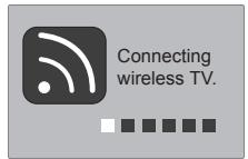
If you turn on the power of the TV when the external input of the Wireless Media Box is selected, it will be displayed when the external input of the Wireless Media Box is trying to connect to the wireless network.
This is the screen displayed when trying to connect wireless (external input) after connecting the Wireless Ready Dongle while the TV is turned off.
The screen becomes dark briefly right before the connection process is complete.
- When the connection fails, check the power of the Wireless Media Box.

- Left icon is to distinguish the external input of TV and the wireless external input of Wireless Media Box.
- After the Wireless Ready Dongle is successfully installed, wireless external input will be shown additionally in the TV menu related to external input. (Input List, Input Label, Timer, Input Block and Picture Wizard)
- Operate the external input of Wireless Media Box using the remote controller of the TV.
- When an external device is connected to the Media Box, if the wireless connection is disconnected while the user is changing the settings for video, audio, and other options, the changed settings may not be applied completely. If this occurs, try to carry out the setup again when a wireless device is connected.

- When you press the OK button while viewing the external input of Wireless Media Box, the information of the current input and the strength of the wireless signal will be displayed on the bottom left side. (When you press the BACK/EXIT button, the information will disappear.)
If you press the / (Power) button of the Wireless Media Box manually to turn it off when both the TV and Wireless Media Box are turned on, you will not be able to turn on the power using the remote controller of the TV. At this time, press the / (Power) button of the Wireless Media Box to turn on the power.
WATCHING TV / PROGRAM CONTROL
INPUT LIST
Only input signals which are connected to a TV or Wireless Media Box can be activated and selected.
Image shown may differ from your TV.
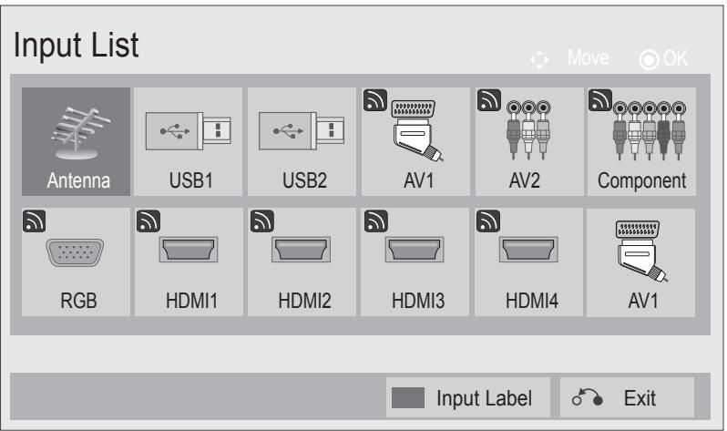
- This is the screen when the Wireless Ready Dongle is connected to HDMI/DVI IN 1. HDMI terminal connected to Wireless Ready Dongle is not displayed on the list of external inputs.
Select your desired Source.
When you change the input source, it can take up to 10 seconds depending on the wireless environment.
IR BLASTER SETUP
You can control the external device (VCR, DVD player etc.) connected to the Media box from the TV using the infrared controller called IR-Blaster.
Set up the TV menu as shown below.

Select OPTION.
Select IR Blaster.
Select On.
- Press the MENU/EXIT button to return to normal TV viewing.
- Press the BACK button to move to the previous menu screen.
APPENDIX
IR CODE LIST
DVD
| BRAND | CODE |
| PHILIPS | RC6 |
| SAMSUNG | LC7461 |
| TOSHIBA | NEC |
| PANASONIC | AV162 |
| LG | TC9012 |
| DENON | LRC3715 |
| PIONEER | NEC |
| HITACHI | NEC |
| GPX | SAA3004 |
AUDIO
| BRAND | CODE |
| DENON | LRC3715 |
| YAMAHA | NEC |
| MARANTZ | SAA3010 |
| INTEGRA, ONKYO | NEC |
| H/K | NEC |
| PIONEER | NEC |
| BOSE | NEC |
| LEXICON | uPD6121 |
| ROTEL | uPD6121 |
| SHERWOOD | uPD6121 |
| XM | SAA3010 |
| REALISTIC | TC9148 |
| PARASOUND | TC9132P |
| INSIGNIA | SAA3004 |
DVR-VCR
| BRAND | CODE |
| TIVO S2 | uPD6121 |
| SAMSUNG | TC9012 |
| TOSHIBA | NEC |
| PANASONIC | AV162 |
| PHILIPS | SAA3010 |
| HITACHI | NEC |
| LG | NEC |
| MITSUBISHI | JVC |
| HITACHI | M50110 |
| GO VIDEO | SAA3004 |
CBL-SAT
| BRAND | CODE |
| S/A,PIONEER | D6108 |
| MOTOROLA | MOTOROLA |
| DIRECTV | DIRECTV |
| MOXI | MOXI |
| VOOM | BU5962 |
| SAMSUNG | uPD6121 |
| LG | NEC |
| PIONEER | M50110 |
RF SPECIFICATIONS
Wireless Media Box
| Items | U-NII-I | U-NII-II | U-NII-II extended | U-NII-III |
| Frequency range [GHz] | 5.15 to 5.25 | 5.25 to 5.35 | 5.47 to 5.725 | 5.725 to 5.825 |
| Transmission | OFDM | OFDM | OFDM | OFDM |
| RF Output Power (Average) [dBm] | 16 | 16 | 16 | 16 |
| Antenna Gain (Peak) [dBi] | 3.47 | 2.93 | 3.42 | 3.24 |
| Channel Table [MHz] (Center frequency) | Depends on the country region (Please see the Frequency Table) | |||
| Channel units | 2 to 11 | |||
| Depends on the country region (Please see the Frequency Table) | ||||
| Maximum distance (Line of sight, No interference) | 15 m | |||
| Depends on the structure of building. | ||||
| Channel bandwidth | 40 MHz | |||
Band channel used by the country could be different.
Wireless Ready Dongle
| Items | U-NII-I | U-NII-II | U-NII-II extended | U-NII-III |
| Frequency range [GHz] | 5.15 to 5.25 | 5.25 to 5.35 | 5.47 to 5.725 | 5.725 to 5.825 |
| Transmission | OFDM | OFDM | OFDM | OFDM |
| RF Output Power (Average) [dBm] | 13 | 13 | 13 | 13 |
| Antenna Gain (Peak) [dB] | 3.36 | 3.05 | 2.72 | 3.17 |
| Channel Table [MHz] (Center frequency) | Depends on the country region (Please see the Frequency Table) | |||
| Channel units | 2 to 11 | |||
| Depends on the country region (Please see the Frequency Table) | ||||
| Channel bandwidth | 20 MHz, 40 MHz | |||
- The product automatically discontinue transmission in case of either absence of information to transmit or operational failure.
FREQUENCY TABLE
| BW/CH | #36 | #40 | #44 | #48 | #52 | #56 | #60 | #64 | #100 | #104 | #108 | #112 | #116 | #120 | #124 | #128 | #132 | #136 | #140 | #149 | #153 | #157 | #161 | #165 | ||||
| EUROPE / Russia / Kazakhstan / Uzbekistan / Kyrgyzstan / Tadjikistan / Turkmenistan / Belarus / Turkey | 5.15 GHz to 5.25 GHz | 5.25 GHz to 5.35 GHz | 5.47 GHz to 5.725 GHz | 5.725 GHz to 5.850 GHz | ||||||||||||||||||||||||
| 20 MHz | 5180 | 5200 | 5220 | 5240 | 5260 | 5280 | 5300 | 5320 | 5500 | 5520 | 5540 | 5560 | 5580 | 5600 | 5620 | 5640 | 5660 | 5680 | ||||||||||
| 40 MHz | 5190 | 5230 | 5270 | 5310 | 5510 | 5550 | 5590 | 5630 | 5670 | |||||||||||||||||||
| Ukraine | 5.15 GHz to 5.25 GHz | 5.25GHz to 5.35 GHz | 5.47 GHz to 5.725 GHz | 5.725 GHz to 5.850 GHz | ||||||||||||||||||||||||
| 20 MHz | 5180 | 5200 | 5220 | 5240 | 5260 | 5280 | 5300 | 5320 | 5500 | 5520 | 5540 | 5560 | 5580 | 5600 | 5745 | 5765 | 5785 | 5805 | ||||||||||
| 40 MHz | 5190 | 5230 | 5270 | 5310 | 5510 | 5550 | 5590 | 5755 | 5795 | |||||||||||||||||||
| Algeria | 5.15 GHz to 5.25 GHz | 5.25 GHz to 5.35 GHz | 5.47 GHz to 5.725 GHz | 5.725 GHz to 5.850 GHz | ||||||||||||||||||||||||
| 20 MHz | 5180 | 5200 | 5220 | 5240 | 5260 | 5280 | 5300 | 5320 | 5745 | 5765 | 5785 | 5805 | ||||||||||||||||
| 40 MHz | 5190 | 5230 | 5270 | 5310 | 5755 | 5795 | ||||||||||||||||||||||
| Morocco / Tunisia | 5.15 GHz to 5.25 GHz | 5.25 GHz to 5.35 GHz | 5.47 GHz to 5.725 GHz | 5.725 GHz to 5.850 GHz | ||||||||||||||||||||||||
| 20 MHz | 5180 | 5200 | 5220 | 5260 | 5280 | 5300 | 5320 | |||||||||||||||||||||
| 40 MHz | 5190 | 5230 | 5270 | 5310 | 5755 | 5795 | ||||||||||||||||||||||
- The user can not change or adjust the operating frequency and this product is set for the regional frequency table.
PRODUCT SPECIFICATIONS
| MODELS | Wireless Media Box (AN-WL100E / AN-WL100ET) | |
| Dimensions (Width x Height x Depth) | 326.0 mm x 42.8 mm x 226.0 mm | |
| Weight | 1.5 kg | |
| Power requirement | DC 12 V 1.1 A | |
| Adapter | In: AC 100-240 V~ 50 / 60 Hz Out: DC 12 V 2.5A (Adapter model No.: PA-1031-1 (LITE-ON), EADP-30PB B (DELTA)) | |
| MODELS | Wireless Ready Dongle | |
| Dimensions (Width x Height x Depth) | 148.0 mm x 23.0 mm x 78.0 mm | |
| Weight | 0.2 kg | |
| Environment condition | Operating Temperature | 0 °C to 40 °C Less than 80 % |
| Operating Humidity | ||
| Storage Temperature | -20 °C to 60 °C | |
| Storage Humidity | Less than 85 % | |
The specifications shown above may be changed without prior notice for quality improvement.
TROUBLESHOOTING
| The video function does not work. | |
| No picture & No sound | ■ Check whether the TV and the Wireless Media Box are turned on. ■ Is the power cord inserted correctly into the adapter? ■ Is the adapter plug inserted correctly into the Wireless Media Box? |
| No or poor colour or poor picture | ■ Adjust Colour in menu option. ■ Are the video cables installed properly? ■ Activate any function to restore the brightness of the picture. |
| Horizontal/vertical bars or picture shaking | ■ Check for local interference such as an electrical appliance or power tool. |
| No picture when connecting HDMI | ■ Check that your HDMI cable is High Speed HDMI Cable. If the HDMI cables are not High Speed HDMI Cable, flickering or no screen display can result. Please use the High Speed HDMI Cable. |
| The audio function does not work. | |
| Picture OK & No sound | Press the ▲+ or - button. Sound muted? Press MUTE button. Are the audio cables installed properly? |
| No output from one of the speakers | Adjust Balance in menu option. |
| No sound when connecting HDMI | Check HDMI cable is High Speed HDMI Cable. |
| There is a problem in PC mode. (Only PC mode applied) | |
| The signal is out of range (Invalid format) | ■ Adjust resolution, horizontal frequency, or vertical frequency. ■ Check the input source. |
| Vertical bar or stripe on background & Horizontal Noise & Incorrect position | ■ Use Auto configure or adjust clock, phase, or H/V position. (Option) |
| Screen colour is unstable or single colour | ■ Check the signal cable. ■ Reinstall the PC video card. |
| This is when there is an issue with the wireless connection. | |
| Connecting Wireless TV screen is not displayed. | ■ Check the connection of the 20 pin cable (Power/Control) between the Wireless Ready TV and Wireless Ready Dongle. (Refer to the p. 6) ■ Set up the external input of TV to wireless input. ■ Check the connection of the HDMI cable between the Wireless Ready TV and Wireless Ready Dongle. (Refer to the p. 6) |
| "Connecting wireless" screen is displayed but the wireless input is not activated. | ■ Check whether the power of the Wireless Media Box is turned on. (Refer to the p. 18 to 19) ■ Check whether an external device is connected to Wireless Media Box. Only the wireless input with the external device connected will be activated. |
| It reconnects after wire-less connection is established | ■ This happens when there is wireless interference from surrounding devices or when the wireless signal is weak. Check the installation range of the Wireless Media Box. (Refer to the p. 9) |
| Screen is distorted after the wireless connection. | ■ This can happen when the wireless signal is weak. Check the installation range of the Wireless Media Box. (Refer to the p. 9) |
| After wireless connection is established, horizontal line patterns are instantly shown on the screen. | ■ This can happen when there are wireless devices using 5 GHz Band. Keep products that interfere with wireless reception with Wireless Media Box at least 5 m away. (Refer to the p. 9) |
APPENDIX
OPEN SOURCE SOFTWARE NOTICE
The following GPL executables and LGPL, MPL libraries used in this product are subject to the GPL2.0/ LGPL2.1/MPL1.1 License Agreements:
GPL EXECUTABLES:
Linux kernel 2.6, busybox, e2fsprogs, gdbserver, jfsutils, mtd-utils, procps, u-boot, udhcpc
LGPL LIBRARIES:
Cairo, directFB, gconv, gettext, glib, glibc, iconv, pixman
MPL LIBRARIES:
Nanox
LG Electronics offers to provide source code to you on CD-ROM for a charge covering the cost of performing such distribution, such as the cost of media, shipping and handling upon e-mail request to LG Electronics at: opensource@lge.com
This offer is valid for a period of three (3) years from the date of the distribution of this product by LG Electronics.
You can obtain a copy of the GPL, LGPL, MPL licenses on the CD-ROM provided with this product.
Also you can obtain the translation of GPL, LGPL licenses from http://www.gnu.org/licenses/old-licenses/gpl-2.0-translations.html, http://www.gnu.org/licenses/old-licenses/lgpl-2.1-translations.html.
This product includes other open source software
expat:
-
copyright © 1998, 1999, 2000 Thai Open Source Software Center Ltd and Clark Cooper
-
copyright © 2001, 2002, 2003, 2004, 2005, 2006 Expat maintainers.
freetype: copyright © 2003 The FreeType Project (www.freetype.org).
ICU: copyright © 1995-2008 International Business Machines Corporation and others.
libcurl: copyright © 1996 - 2008, Daniel Stenberg.
libjpeg: This software is based in part on the work of the Independent JPEG Group copyright © 1991 - 1998, Thomas G. Lane.
libmng: copyright © 2000-2007 Gerard Juyn, Glenn Randers-Pehrson
libpng: copyright © 1998-2008 Glenn Randers-Pehrson
ncurses: copyright © 1998 Free Software Foundation, Inc.
openSSL:
- cryptographic software written by Eric Young.
- software written by Tim Hudson.
- software developed by the OpenSSL Project for use in the OpenSSL Toolkit. (http://www.openssll.org)
strace:
- copyright © 1991, 1992 Paul Kranenburg.
copyright © 1993 Branko Lankester. - copyright © 1993 Ulrich Pegelow.
- copyright © 1995, 1996 Michael Elizabeth Chastain.
- copyright © 1993, 1994, 1995, 1996 Rick Sladkey.
- copyright © 1998-2003 Wichert Akkerman.
- copyright © 2002-2008 Roland McGrath.
- copyright © 2003-2008 Dmitry V. Levin.
- copyright © 2007-2008 Jan Kratochvil.
▶ zlib: copyright © 1995-2005 Jean-Ioup Gailly and Mark Adler
All rights reserved.
Permission is hereby granted, free of charge, to any person obtaining a copy of this software and associated documentation files (the "Software"), to deal in the Software without restriction, including without limitation the rights to use, copy, modify, merge, publish, distribute, sublicense, and/or sell copies of the Software, and to permit persons to whom the Software is furnished to do so, subject to the following conditions:
THE SOFTWARE IS PROVIDED "AS IS", WITHOUT WARRANTY OF ANY KIND, EXPRESS OR IMPLIED, INCLUDING BUT NOT LIMITED TO THE WARRANTY OF MERCHANTABILITY, FITNESS FOR A PARTICULAR PURPOSE AND NONINFRINGEMENT. IN NO EVENT SHALL THE AUTHORS OR COPYRIGHT HOLDERS BE LIABLE FOR ANY CLAIM, DAMAGES OR OTHER LIABILITY, WHETHER IN AN ACTION OF CONTRACT, TORT OR OTHERWISE, ARISING FROM, OUT OF OR IN CONNECTION WITH THE SOFTWARE OR THE USE OR OTHER DEALINGS IN THE SOFTWARE.

LG
Life's Good
Record the model number and serial number of the TV.
Refer to the label on the back cover and quote this information to your dealer when requiring any service.
Model :
Serial No.: