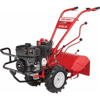
Big Red - Plane TROY-BILT - Free user manual and instructions
Find the device manual for free Big Red TROY-BILT in PDF.



| Product type | Rear-tine tiller |
| Brand | Troy-Bilt |
| Model | Big Red (Horse/Big Red) |
| Weight | 280 to 325 lb (127 to 147 kg) |
| Fuel | Unleaded gasoline |
| Starting type | Manual (recoil starter) or electric (depending on version) |
| Number of tines | 16 Bolo tines (12 inches) |
| Wheel speeds | 2 forward speeds (slow/fast) + reverse + freewheel |
| Belt ranges | 2 ranges: high and low |
| Tilling depth | Adjustable by lever (max about 6-8 inches) |
| Tire pressure | 10 to 20 psi (both tires at same pressure) |
| Power take-off (PTO) | Yes, for stationary attachments |
| Main functions | Tilling, composting, seedbed preparation, wide row cultivation, hilling |
| Routine maintenance | Check engine oil, clean cooling fins, check belt, lubrication, tire pressure |
| Cleaning tines | Manual cleaning after engine stop and spark plug disconnection |
| Safety | Stop engine, disconnect spark plug before maintenance, wear goggles and gloves, keep children away |
| Main spare parts | V-belt, Bolo tines, reverse disc, wheels, throttle cable |
| Warranty (domestic use) | 2 years (parts and labor) |
| General information | Manufactured by Troy-Bilt LLC, Canada. Model and serial number on nameplate. |
Frequently Asked Questions - Big Red TROY-BILT
User questions about Big Red TROY-BILT
0 question about this device. Answer the ones you know or ask your own.
Ask a new question about this device
Download the instructions for your Plane in PDF format for free! Find your manual Big Red - TROY-BILT and take your electronic device back in hand. On this page are published all the documents necessary for the use of your device. Big Red by TROY-BILT.
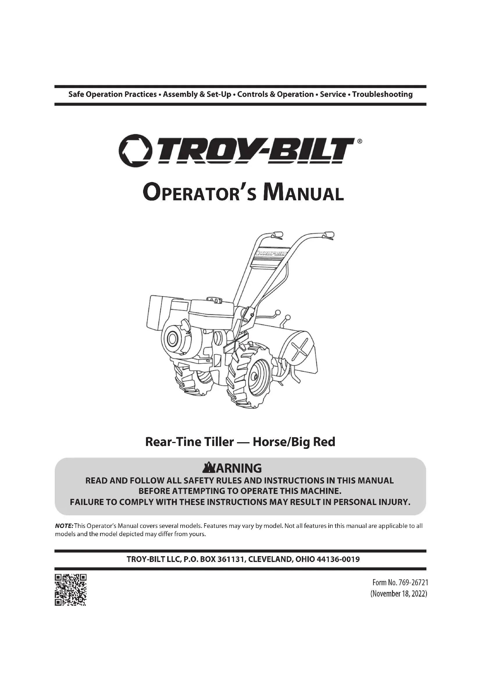
USER MANUAL Big Red TROY-BILT
natural_image
Line drawing of a manual tiller machine with visible blade and handle (no text or symbols)Rear-Tine Tiller — Horse/Big Red
WARNING
READ AND FOLLOW ALL SAFETY RULES AND INSTRUCTIONS IN THIS MANUALBEFORE ATTEMPTING TO OPERATE THIS MACHINE.
FAILURE TO COMPLY WITH THESE INSTRUCTIONS MAY RESULT IN PERSONAL INJURY.
NOTE: This Operator's Manual covers several models. Features may vary by model. Not all features in this manual are applicable to all models and the model depicted may differ from yours.
TROY-BILT LLC, P.O. BOX 361131, CLEVELAND, OHIO 44136-0019
To The Owner
1
Thank You
Thank you for purchasing this product. It was carefully engineered to provide excellent performance when properly operated and maintained.
Please read this entire manual prior to operating the equipment. It instructs you how to safely and easily set up, operate and maintain your machine. Please be sure that you, and any other persons who will operate the machine, carefully follow the recommended safety practices at all times. Failure to do so could result in personal injury or property damage.
All information in this manual is relative to the most recent product information available at the time of printing. Review this manual frequently to familiarize yourself with the machine, its features and operation. Please be aware that this Operator's Manual may cover a range of product specifications for various models. Characteristics and features discussed and/or illustrated in this manual may not be applicable to all models. We reserve the right to change product specifications, designs and equipment without notice and without incurring obligation.
If you have any problems or questions concerning the machine, phone an authorized service dealer or contact us directly. Customer Support telephone numbers, website address and mailing address can be found on this page. We want to ensure your complete satisfaction at all times.
Throughout this manual, all references to right and left side of the machine are observed from the operating position.
The engine manufacturer is responsible for all engine-related issues with regards to performance, power-rating, specifications, warranty and service. Please refer to the engine manufacturer's Owner's/Operator's Manual, packed separately with your machine, for more information.
Table of Contents
Safe Operation Practices....3
Assembly & Set-Up 5
Controls & Operation 8
Service....15
Troubleshooting.... 23
Replacement Parts 24
Warranty 26
Spanish....28
Français 52
Record Product Information
Before setting up and operating your new equipment, please locate the model plate on the equipment and record the information in the provided area to the right. You can locate the model plate by standing at the operator's position and looking down at the rear of the deck. This information will be necessary, should you seek technical support via our web site, Customer Support Department, or with a local authorized service dealer.
MODEL NUMBER

natural_image
Row of identical empty rectangular boxes with no text or symbolsSERIAL NUMBER

natural_image
Row of identical empty rectangular boxes with no text or symbolsCustomer Support
Please do NOT return the machine to the retailer or dealer without first contacting the Customer Support Department.
If you have difficulty assembling this product or have any questions regarding the controls, operation or maintenance of this machine, you can seek help from the experts. Choose from the options below:
◇ Web: www.troybilt.com
◇ Phone: (800) 828-5500 or (330) 558-7220
Mail: Troy-Bilt LLC • P.O. Box 361131 • Cleveland, OH • 44136-0019

WARNING! This symbol points out important safety instructions which, if not followed, could endanger the personal safety and/or property of yourself and others. Read and follow all instructions in this manual before attempting to operate this machine. Failure to comply with these instructions may result in personal injury. When you see this symbol - HEED ITS WARNING!
CALIFORNIA PROPOSITION 65

WARNING! Engine Exhaust, some of its constituents and certain vehicle components contain or emit chemicals known to the State of California to cause cancer and birth defects or other reproductive harm.

WARNING! Battery posts, terminals, and related accessories contain lead and lead compounds, chemicals known to the State of California to cause cancer and reproductive harm. Wash hands after handling.

DANGER! This machine was built to be operated according to the safe operation practices in this manual. As with any type of power equipment, carelessness or error on the part of the operator can result in serious injury. This machine is capable of amputating hands and feet and throwing debris. Failure to observe the following safety instructions could result in serious injury or death.
Training
- Read, understand, and follow all instructions on the machine and in the manual(s) before attempting to assemble and operate. Keep this manual in a safe place for future and regular reference and for ordering replacement parts.
- Be familiar with all controls and their proper operation. Know how to stop the machine and disengage them quickly.
- Never allow children under 14 years of age to operate this machine. Children 14 and over should read and understand the instructions and safe operation practices in this manual and on the machine and be trained and supervised by an adult.
- Never allow adults to operate this machine without proper instruction.
- Keep the area of operation clear of all persons, particularly small children and pets. Stop machine if anyone enters the area.
Preparation
- Thoroughly inspect the area where the equipment is to be used. Remove all stones, sticks, wire, and other foreign objects which could be tripped over and cause personal injury.
- Wear sturdy, rough-soled work shoes and close fitting slacks and shirt. Loose fitting clothes or jewelry can be caught in moving parts. Never operate this machine in bare feet or sandals.
- Disengage clutch levers and shift (if provided) into neutral ("N") before starting the engine.
- Never leave this machine unattended with the engine running.
- Never attempt to make any adjustments while engine is running, except where specifically recommended in the operator's manual.
Safe Handling of Gasoline:
- To avoid personal injury or property damage use extreme care in handling gasoline. Gasoline is extremely flammable and the vapors are explosive. Serious personal injury can occur when gasoline is spilled on yourself or your clothes, which can ignite. Wash your skin and change clothes immediately.
- Use only an approved gasoline container.
- Never fill containers inside a vehicle or on a truck or trailer bed with a plastic liner. Always place containers on the ground away from your vehicle before filling.
- When practical, remove gas-powered equipment from the truck or trailer and refuel it on the ground. If this is not possible, then refuel such equipment on a trailer with a portable container, rather than from a gasoline dispenser nozzle.
- Keep the nozzle in contact with the rim of the fuel tank or container opening at all times until fueling is complete. Do not use a nozzle lock-open device.
- Extinguish all cigarettes, cigars, pipes, and other sources of ignition.
- Never fuel machine indoors.
- Never remove gas cap or add fuel while the engine is hot or running. Allow engine to cool at least five minutes before refueling.
- Never over fill fuel tank. Fill tank to no more than 1/2 inch below bottom of filler neck to allow space for fuel expansion.
- Replace gasoline cap and tighten securely.
- If gasoline is spilled, wipe it off the engine and equipment. Move unit to another area. Wait five minutes before starting the engine.
• If fuel is spilled on clothing, change clothing immediately.
• To reduce fire hazards, keep machine free of grass, leaves, or other debris build-up. Clean up oil or fuel spillage and remove any fuel soaked debris. - Never store the machine or fuel container inside where there is an open flame, spark, or pilot light as on a water heater, space heater, furnace, clothes dryer, or other gas appliances.
Operation
- Do not put hands or feet near rotating parts. Contact with the rotating parts can amputate hands and feet.
-
Always wear safety glasses or safety goggles during operation and while performing an adjustment or repair to protect your eyes. Thrown objects which ricochet can cause serious injury to the eyes.
-
For extended use of this product, hearing protection is required.
- Do not operate machine while under the influence of alcohol or drugs.
- Never operate this machine without good visibility or light. Always be sure of your footing and keep a firm hold on the handles.
- Keep bystanders away from the machine while it is in operation. Stop the machine if anyone enters the area.
- Be careful when tilling in hard ground. The tines may catch in the ground and propel the tiller forward. If this occurs, let go of the handlebars and do not restrain the machine.
- Exercise extreme caution when operating on or crossing gravel surfaces. Stay alert for hidden hazards or traffic. Do not carry passengers.
- Never operate the machine at high transport speeds on hard or slippery surfaces.
- Exercise caution to avoid slipping or falling.
- Look down and behind and use care when in reverse or pulling machine towards you.
- Start the engine according to the instructions found in this manual and keep feet well away from the tines at all times.
- After striking a foreign object, stop the engine, disconnect the spark plug wire, and ground against the engine. Thoroughly inspect the machine for any damage. Repair the damage before starting and operating.
- Disengage all clutch levers (if fitted) and stop engine before you leave the operating position (behind the handles). Wait until the tines come to a complete stop before unclogging the tines or making any adjustments or inspections.
- Never run an engine indoors or in a poorly ventilated area. Engine exhaust contains carbon monoxide, an odorless and deadly gas.
- Muffler and engine become hot and can cause a burn. Do not touch.
- Use caution when tilling near fences, buildings, and underground utilities. Rotating tines can cause property damage or personal injury.
-
Do not overload machine capacity by attempting to till soil too deep at too fast of a rate.
-
If the machine should start making an unusual noise or vibration, stop the engine, disconnect the spark plug wire, and ground it against the engine. Inspect thoroughly for damage. Repair any damage before starting and operating.
- Keep all shields, guards, and safety devices in place and operating properly.
- Never pick up or carry machine while the engine is running.
- Powered walk-behind tiller work is strenuous. You must be in good physical condition and mentally alert. If you have any condition that might be aggravated by strenuous work, check with your doctor before operating a powered walk-behind tiller.
- Use only attachments and accessories approved by the manufacturer. Failure to do so can result in personal injury.
- If situations occur which are not covered in this manual, use care and good judgement. Contact Customer Support for assistance and the name of your nearest servicing dealer.
Maintenance & Storage
- Keep machine, attachments, and accessories in safe working order.
- Never store the machine with fuel in the fuel tank inside a building where ignition sources are present, such as hot water and space heaters, clothes dryers, etc.
-
Allow machine to cool at least five minutes before storing. Never tamper with safety devices. Check their proper operation regularly.
-
Check bolts and screws for proper tightness at frequent intervals to keep the machine in safe working condition. Also, visually inspect machine for any damage.
- Before cleaning, repairing, or inspecting, stop the engine and make certain the tines and all moving parts have stopped. Disconnect the spark plug wire and ground it against the engine to prevent unintended starting.
- Do not change the engine governor settings or over-speed the engine. The governor controls the maximum safe operating speed of the engine.
- Maintain or replace safety and instruction labels, as necessary.
- Follow this manual for safe loading, unloading, transporting, and storage of this machine.
- Always refer to the Operator's Manual for important details if the machine is to be stored for an extended period.
- If the fuel tank has to be drained, do this outdoors.
- Observe proper disposal laws and regulations for gas, oil, etc. to protect the environment.
- According to the Consumer Products Safety Commission (CPSC) and the U.S. Environmental Protection Agency (EPA), this product has an Average Useful Life of seven (7) years, or 130 hours of operation. At the end of the Average Useful Life have the machine inspected annually by an authorized service dealer to ensure that all mechanical and safety systems are working properly and not worn excessively. Failure to do so can result in accidents, injuries, or death.
Notice Regarding Emissions
Engines which are certified to comply with California and Federal EPA emission regulations for SORE (Small Off Road Equipment) are certified to operate on regular unleaded gasoline, and may include the following emission control systems: Engine Modification (EM), Oxidizing Catalyst (OC), Secondary Air Injection (SAI), and Three Way Catalyst (TWC), if so equipped.
Spark Arrestor

WARNING! This machine is equipped with an internal combustion engine and should not be used on or near any unimproved forest-covered, brush-covered, or grass-covered land unless the engine's exhaust system is equipped with a spark arrestor meeting applicable local or state laws (if any).
If a spark arrestor is used, it should be maintained in effective working order by the operator. In the State of California the above is required by law (Section 4442 of the California Public Resources Code). Other states may have similar laws. Federal laws apply on federal lands.
A spark arrestor for the muffler is available through your nearest engine authorized service dealer or contact the service department, P.O. Box 361131 Cleveland, Ohio 44136-0019.
Safety Symbols
This page depicts and describes safety symbols that may appear on this product. Read, understand, and follow all instructions on the machine before attempting to assemble and operate.
| Symbol Description | |
| READ THE OPERATOR'S MANUAL(S)Read, understand, and follow all instructions in the manual(s) before attempting to assemble and operate. | |
| WARNING—ROTATING TINESDo not put hands or feet near rotating parts. Contact with the rotating parts can amputate hands and feet. | |

WARNING! Your Responsibility—Restrict the use of this power machine to persons who read, understand, and follow the warnings and instructions in this manual and on the machine.
SAVE THESE INSTRUCTIONS!
Assembly & Set-Up
3
Contents of Carton
• Tiller (1)
• Handlebar Support (1)
• Handlebar Assembly (1)
- Hardware Pack (1)
- Wheels/Tines PTO Lever (1)
Operator's Manual (1)
• Engine Operator's Manual (1)

WARNING! To prevent personal injury or property damage, do not start the engine until all assembly steps are complete and you have read and understand the safety and operating instructions in this manual.
Recommended Tools for Assembly
- 3/8" open-end wrench (1)
- 7/16" open-end wrench (2)
- 1/2" open-end wrench (2)
- 9/16" open-end wrench (1)
- 3/4" open-end wrench (1)
- Flat blade screwdriver (1)
• Scissors (to trim plastic ties) - Tire pressure gauge (1)
- 4-1/2" high wood block to prop machine
Contents of Hardware Pack
- Bottle of Oil (1)
- Clutch Pawl Spring (1)
- Belt Adjusting Tool (1)
- Plastic Cable Ties (2)
• Hex Screw, 1/4-20: 2.5" (1)
• Flanged Lock Nut, 1/4-20 (1) - Flat Washer .260 x .720 x .060 (1)
NOTE: The following parts (electric start models only) packaged separately.
• Nuts, 1/4-20 for battery terminals (2)
- Screws, 1/4-20 x 5/8 for battery terminals (2)
- Keys in ignition switch (2)
Assembly
Unpacking Instructions
NOTE: Do not severely bend any of the control cables on the tiller.
- The tiller is heavy. Do not attempt to remove it from the shipping platform until instructed to do so in these assembly steps.
- Remove all loose parts from the carton. The hardware bag is included in your literature packaging.
- Check that you have the items listed above (contact your local dealer or the Troy-Bilt Technical Service Department if any items are missing or damaged).
Handle
NOTE: When disassembling the handlebar assembly, keep the left-side clamp and ratchet separated from the right-side clamp and ratchet.
- Disassemble the handlebar assembly. To do this, remove the height adjustment lever by turning the lever in a counter-clockwise direction. See Figure 3-1.
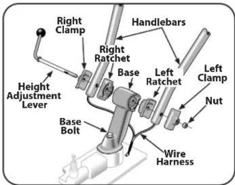
Figure 3-1
- Place the handlebar ends on either side of the base, with the wire harness toward the rear of the base. See Figure 3-1.
- Install the height adjustment lever through the right-side clamp, handlebar end, ratchet and base; then out through the left-side ratchet, handlebar end and clamp. See Figure 3-1. Secure with the nut, but do not fully tighten.
NOTE: Do not force the height adjustment lever through the handlebars. The interlock wires may be blocking the lever and could be damaged. You may gently move the wires aside if this condition occurs.
- Raise the handlebars to one of two height settings and tighten the height adjustment lever. Also, make sure all other mounting hardware is securely tightened.
Moving the Tiller off the Shipping Platform
- Set the Depth Regulator Lever to the "TRAVEL" position. Do this by lifting the tiller by the handlebars, then pulling straight back on the lever and sliding down to the highest notched setting. See Figure 3-2.
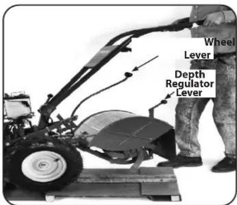
Figure 3-2
- Set the Wheel Speed Lever to the Freewheel position. To do this, move the lever approximately halfway between the Fast and Slow settings while you rock the tiller forward and backward until the wheels move freely. See Figure 3-2.
- Lift the Handlebars high enough to clear the tiller tines and pull back firmly to dislodge the tiller from the platform wheel wells.
Wire Harness
- Ground the green (and red for electric start tillers) wire(s) to the engine block. See Figure 3-3.
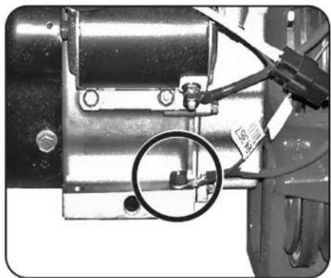
natural_image
Close-up of a mechanical assembly with a magnified inset showing a detail (no visible text or symbols)Figure 3-3
- Connect the safety wire assembly (green and yellow wires). See Figure 3-4.
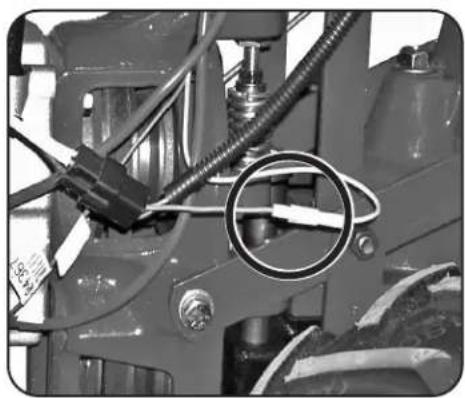
natural_image
Close-up of a mechanical assembly with hoses and a circular component (no visible text or symbols)Figure 3-4
- Connect the tiller's main harness connection to the neutral safety switch receptacle. See Figure 3-5.
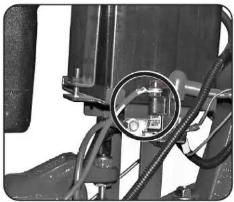
natural_image
Close-up of a mechanical assembly with visible wiring and a circular component (no text or symbols)Figure 3-5
Wheels/Tines PTO Drive Lever
- Loosen the bolt on the handlebar base and swing the handlebars out to the right side. See Figure 3-1 on page 5.
- Remove both sets of nuts, star washers, screws and one bushing from the yoke plates. See Figure 3-6. There is a bushing inside the short link. Be careful not to lose it when removing screw.
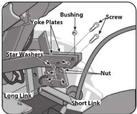
Figure 3-6
- Slide the plates at the end of the Wheels/Tines/PTO Drive Lever over the yoke plates. See Figure 3-7. To aid in the next step, insert a screw temporarily into the forward-most holes of the yoke plates and the lever.
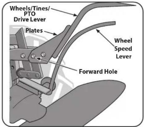
Figure 3-7
- Align the rear-most holes of the yoke plates and the Wheels/Tines PTO Drive Lever. Use long nose pliers to hold the bushing in place while inserting the screw through the lever and yoke plates. See Figure 3-8. Install the star washer and the nut then hand tighten.
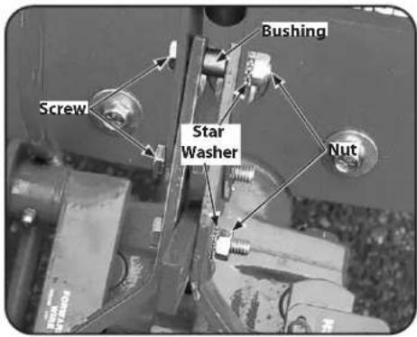
Figure 3-8
- Retrieve the clutch pawl spring from hardware bag. Remove the temporary screw from the forward holes inserted in Step 3 and move the Wheels/Tines/PTO Drive Lever fully forward. Install the wider hook end of the clutch pawl spring down into the small hole at the end of the handle. Use pliers to insert the other end into the hole in the long link bar. See Figure 3-9.
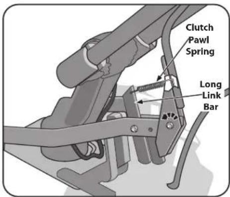
Figure 3-9
NOTE: Do not bend or over-stretch the spring while installing.
- Pull the Wheels/Tines/PTO Lever back to align the forward most holes in the yoke plate with the holes in the lever plates. Also align the bushing that is inside the short link bar. Install the screw, star washer and nut, then tighten securely. Securely tighten all other hardware. Ensure that the spring is properly seated at both ends. Completed assembly should appear as illustrated in Figure 3-10.
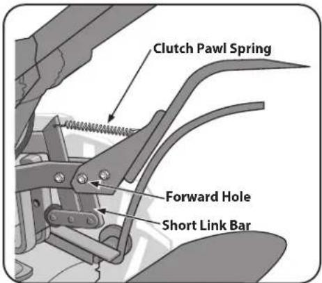
Figure 3-10
- Test the operation of the Wheels/Tines/ PTO Drive Lever. Push the lever down until it engages in the Forward position. The clutch roller must rest beneath the adjustment block. Next, move the lever up to the Neutral position. See Figure 3-11.
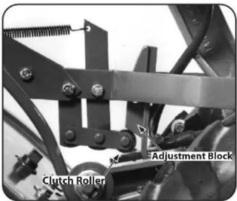
Figure 3-11
- To test Reverse, lift and hold the lever all the way up in the Reverse position, then let it go. The lever should automatically return to the Neutral position. See Figure 3-12. If not, do not use the tiller. See your local authorized dealer or call the Troy-Bilt Technical Service Department for instructions.
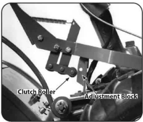
Figure 3-12
Engine Throttle Lever and Cable
For shipping purposes, the throttle cable, together with the throttle lever, is wound around the engine. Carefully unwind the cable. If the throttle control label is covered with a clear protective coating, peel it off.

WARNING! To avoid electric shock from a short circuit (electric start tillers only), never allow the throttle cable to touch the battery. Route the cable below the battery, on the outside of the battery holder.
To attach the throttle lever and cable:
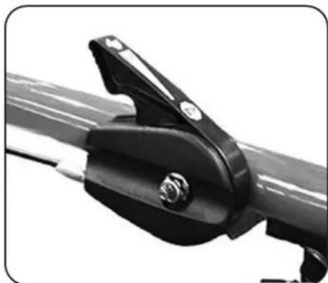
- Run the throttle cable up the inside edge of the right handlebar and position the lever as shown in Figure 3-13.
natural_image
Close-up of a black metal clamp bracket with a screw and threaded rod (no text or symbols visible)Figure 3-13
- From the outside of the handlebar, insert the 2.5" hex screw from the hardware pack through the flat washer, the handlebar and the center hole in the throttle lever mounting bracket. See Figure 3-13.
- Loosely install the flanged lock nut and pull the throttle lever back to the STOP position.
- Ensure the groove in the throttle housing is flush with the handlebar. Securely tighten the flanged lock nut and the hex screw. See Figure 3-13.
- Use two plastic ties to secure the throttle cable to the right handlebar in two places. Loop each tie around the handlebar and cable (serrated side faces in) and pull the ties tight. Trim the ends.
Electric Start System (If Equipped)
The following steps explain how to install and charge the battery on electric start tillers. For your safety, follow all steps and observe all accompanying safety messages. The Service section contains other general battery maintenance and recharging instructions.

WARNING! Battery produces explosive gases. Keep away sparks, flames, and cigarettes. Ventilate area when charging or using battery in an enclosed space. Make sure battery vent tube is always open after battery is filled with acid.

WARNING! Remove metal jewelry before working near the battery or near the electrical system. Failure to comply may cause a short circuit, resulting in electrical burns, a shock, or battery gas explosion.
NOTE: If the battery is put into service after the date shown on the top of the battery, charge for a minimum of one hour at 6-10 amps. Refer to the Service section of this manual for more detailed instructions regarding proper battery charging procedure.

WARNING! Never jump start the battery with a vehicle battery or charging system. This may produce a battery explosion, causing acid or electrical burns.
- Before installing the battery and its hold-down clamp, insert the plastic wire harness receptacle into the prongs of the keyswitch located on the hold-down clamp. See Figure 3-14.
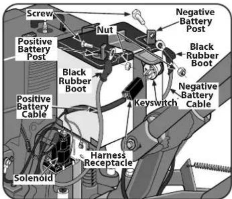
Figure 3-14
- Remove the ignition keys from the keyswitch and store them safely away. Do not insert the key into the keyswitch until you complete this section and read the Operation section. See Figure 3-14.
- Use a 5/8" long screw and 1/4-20 hex nut to connect the positive (+) battery cable to the positive (+) battery post. Make sure that this is the cable on the left side, with one end attached to the solenoid. See Figure 3-14.

WARNING! To Avoid Personal Injury or Property Damage: Do not touch the positive battery terminal and any surrounding metal objects with tools, jewelry, or other metal items. Failure to comply could cause a short circuit leading to electrical burns or an explosion of battery gases. Never bring a gas can near the positive (+) battery terminal. A short circuit could occur leading to an explosion of the gasoline or the battery gases. Always fill the engine fuel tank from the front or side of the engine.
- Slide the black rubber boot completely over the battery post and cable connector. See Figure 3-14.
- Use a 5/8" long screw and 1/4-20 hex nut to connect the negative (-) battery cable to the negative (-) battery post and secure with screw and nut. See Figure 3-14.
- Slide the black rubber boot completely over the battery post and cable connector. See Figure 3-14.
Set-Up
Tires
For shipping purposes, the tires may be over-inflated. Check the air pressure in each tire and adjust them to between 10 and 20 pounds per square inch. You must inflate each tire to equal air pressures to prevent the tiller from pulling to one side.
Gas & Oil Fill-up
Service the engine with gasoline and oil as instructed in the Engine Operator's Manual packed separately with your tiller. Read the instructions carefully.

WARNING! Use extreme care when handling gasoline. Gasoline is extremely flammable and the vapors are explosive. Never fuel the machine indoors or while the engine is hot or running. Extinguish cigarettes, cigars, pipes, and any other sources of ignition.
Transmission Gear Oil
The transmission was filled with gear oil at the factory. However, be sure to check the oil level at this time to make certain it is correct. See the Service section for instructions on checking and adding transmission gear oil.
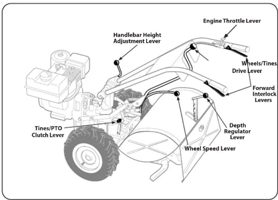
Figure 4-1
Controls

WARNING! Be familiar with all the controls and their proper operation. Know how to stop the machine and disengage them quickly.
NOTE: For detailed information on all engine controls refer to the separate Engine Operator's Manual.
Wheels/Tines/PTO Drive Lever
Use the Wheels/Tines/PTO Drive Lever to engage and disengage power to the transmission.
Forward Interlock Levers
The Forward Interlock Levers are attached under the handlebar grip and will stop the engine if both levers are released.
Wheel Speed Lever
The Wheel Speed Lever controls the speed at which the wheels spin.
Tines/PTO Clutch Lever
The Tines/PTO Clutch Lever is used to engage or disengage power to the transmission.
Depth Regulator Lever
The Depth Regulator Lever is used to regulate the tilling depth of the tines.
Handlebar Height Adjustment Lever
The Handlebar Height Adjustment Lever is used to adjust the handlebars to one of two heights.
Engine Throttle Lever
Use the throttle lever to adjust engine speed as well as to start and stop the engine.
Keyswitch Starter (If So Equipped)
The keyswitch starter on electric start models is used to start, run and stop the tiller.
Starting the Engine
The following steps describe how to start and stop the engine.
NOTE: Do not attempt to engage the tines, wheels or any PTO attachment until you have read all of the operating instructions in this section.
Pre-Start Checklist
Make the following checks and perform the following services before starting the engine.
-
Read the Safe Operation Practices and Controsl & Operation sections in this Manual. Read the separate Engine Operator's Manual.
-
Check the tiller for loose or missing hardware. Service as required.
-
Check the engine oil level. See Engine Operator's Manual.
-
Shift the Wheels/Tines/PTO Drive Lever into NEUTRAL position. See the Controls and Operations section for more information on this lever.
-
Check the safety guards. All guards and covers must be securely in place.
-
Check the air cleaner. See the Engine Operator's Manual.
-
Attach the spark plug wire to the spark plug.
-
Check Engine Cooling System. Clear cooling fins and air intake screen of debris. See the Engine Operator's Manual.
-
Select High/Low Belt Speed range.
-
Adjust the Handlebar Height.
-
Fill the fuel tank with gasoline in accordance with the directions in the separate Engine Operator's Manual. Follow all instructions and safety rules carefully.

WARNING! Never run the engine indoors or in an enclosed, poorly ventilated area. Engine exhaust contains carbon monoxide, an odorless and deadly gas. Avoid engine muffler and nearby areas. Temperatures in these areas may exceed 150^ F ( 65^ C).
NOTE: After the first two hours of operation, perform the maintenance procedures shown in the Maintenance Schedule in the Service section of this manual.
Starting the Engine
-
With the engine off, place the Wheels/Tines/PTO Drive Lever in the NEUTRAL position. If in the FORWARD position, tap the lever sharply upward, it should automatically move into NEUTRAL position.
-
Put the Depth Regulator Lever in the TRAVEL position (lever all the way down) so that the tines are off the ground. To do this, lift up on the handlebars, pull the lever back and push it down all the way to the top detent (notched) position.
-
Move the Wheel Speed Lever to either the SLOW or FAST position. Be sure to roll the wheels while shifting the lever until the wheels engage.
NOTE: If using a PTO stationary attachment, move the Wheel Speed Lever into FREEWHEEL and block the wheels to prevent the equipment from moving. See Figure 4-2.
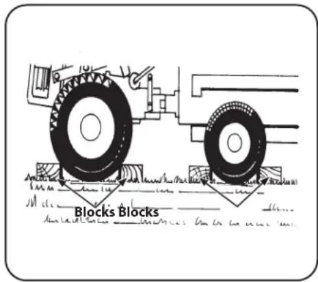
Figure 4-2
- Move the Tines/PTO Clutch Lever into DISENGAGE position.
NOTE: Use the ENGAGE position if you want the tines to revolve or to apply power to a PTO-driven stationary attachment.
-
If the engine is equipped with a fuel valve, turn the valve to the OPEN position as instructed in the separate Engine Operator's Manual.
-
If the engine is equipped with an ON/OFF switch, move the switch to ON. Move engine throttle lever away from STOP. Choke or prime the engine as instructed in the separate Engine Operator's Manual.
-
If not equipped with an electric start system, place one hand on the fuel tank to stabilize the tiller when you pull the recoil starter rope.
-
If equipped with an electric start system, turn the key to START position to crank the engine then release when the engine starts. If the engine does not start right away, do not hold the key at START for more than a few seconds. Release then try again after a short pause. Damage to the starter motor can occur if it is cranked more than 15 seconds per minute.
- If the engine does not start after a number of tries, refer to the Engine Operator's Manual for specific instructions.
- When the engine starts, move the engine throttle lever to the SLOW position and then gradually move the choke lever (on engines so equipped) to OFF or RUN position.
- Move the throttle speed control to FAST setting when tilling.
Starting Electric Start Engine with Recoil Starter
You may, at some point, have to start an electric start engine with the recoil starter rope. Before attempting to do so, perform the following applicable steps:
- If you suspect the battery charge is weak, and there is no visible damage. Disconnect the cables from the battery and clean both cable terminals and the battery posts in accordance with the instructions provided in the Service section. Reconnect the cables and securely tighten to the battery posts. The engine will recharge the battery if the battery is still good.
- If you suspect the batter is "dead", or if the battery is damaged, disconnect and remove it. Have it serviced by an authorized service dealer.
- If the battery has been removed, wrap the cable terminals at the end of the positive cable with electrical tape and secure the cable to the battery bracket. This will prevent electrical discharge.
- Before pulling the recoil starter rope, turn the keyswitch to the RUN position. Move the engine throttle lever away from the STOP position and set the choke as applicable. See the Engine Operator's Manual.
Cold Weather Operation
When temperatures fall below 40^ F ( 4.44^ C), do the following steps to protect your engine and transmission from damage:
- Refer to the Engine Operator's Manual for the motor oil specifications for cold weather operation.
- Use winter blend gasoline.
- Warm the engine up before putting it under a load.
- Use the correct weight gear oil in the PTO Power transmission.
- Warm up the transmission gear oil as follows:
a. With the engine running, move the Wheel Speed Lever to FREEWHEEL (then block the wheels so they cannot roll).
b. Put the Tines/PTO Clutch Lever into DISENGAGE, then squeeze one of the Forward Interlock Levers and shift the Wheels/Tines/PTO Drive Lever to FORWARD.
- If the wheels are frozen to the ground, melt the ice with warm water.
Stopping the Engine and the Tiller
- To stop the wheels and tines, move the Wheels/Tines/PTO Drive Lever into NEUTRAL position and then release both Forward Interlock Levers.
- Move the engine throttle lever to the STOP position. Then, on electric start models only, turn the key to OFF. Remove the key for safekeeping.
NOTE: The engine may have a separate Throttle Control Lever and ON/OFF switch on the engine. These controls can also be used to stop the engine. See the Engine Operator's Manual for information specific to your engine.
Engaging the Drive & Tines
NOTE: This is a traditional standard-rotating-tine (SRT) tiller with forward rotating tines. It operates in a completely different manner than counter-rotating-tine (CRT) tillers, or from front-tine tillers.

WARNING! To help avoid personal injury, be aware that the tiller can unexpectedly bounce up or jump ahead and propel away from you if the tines strike hard or frozen ground, or buried obstacles like large stones, roots, or stumps.
- Start the engine and gradually increase the engine speed to FAST.
- Test the Forward Interlock Safety System. See the Forward Interlock System in the Service section for more information.

WARNING! The Forward Interlock Safety System is designed for the operator's safety. Do not disconnect or attempt to defeat the purpose of the system. If the system malfunctions, immediately contact your local authorized dealer or the Troy-Bilt Technical Service Department for assistance. Do not use the tiller or the PTO power feature until the Forward Interlock Safety System is functioning properly.
- When practicing, set the Depth Regulator Lever to TRAVEL position. Otherwise, set the Depth Regulator Lever to a desired depth.
- Move Tines/PTO Clutch Lever to ENGAGE position if you want the tines to turn. If practicing, leave in DISENGAGE.
NOTE: Do not move Tines/PTO Clutch Lever to ENGAGE unless Wheels/Tines/PTO Drive Lever is in NEUTRAL. Tiller damage may occur.
- To move the tiller forward and engage the tines, squeeze and hold either Forward Interlock Lever against the handlebar grip (see Figure 4-3), then move the Wheels/Tines/PTO Drive Lever down to FORWARD position.
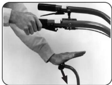
natural_image
Close-up of hands holding a flexible hose with attached cable, no visible text or symbolsFigure 4-3
- When the tiller moves forward, relax and let the wheels power the tiller along while the tines dig. Walk behind and to one side of the tiller. Walk on the side that is not yet tilled. Use a firm grip on the handlebars but keep your arm relaxed. See Figure 4-4.
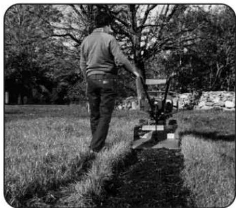
natural_image
Person operating a small tiller in a grassy field, surrounded by trees and rocks (no visible text or symbols)Figure 4-4
NOTE: Let the tiller move ahead at its own pace. Do not push it ahead — this reduces operator control and tilling efficiency. Do not push the handlebars down in an attempt to dig deeper — this takes weight off the wheels, reduces traction and causes the tines to try to propel the tiller.
Stopping Forward Motion & Tines
- To stop forward motion, tap Wheels/Tines/PTO Drive Lever upward into NEUTRAL. Then release the Forward Interlock Levers. The wheels and tines will stop and the engine will continue running.
- In an emergency, release all of the control levers. This stops forward motion and shuts off the engine.
Moving in Reverse

WARNING! To help avoid personal injury or damage to the equipment be sure no obstacles are behind you before operating the tiller in REVERSE. Disengage the tines, reduce engine speed, and move the Wheel Speed Lever to SLOW position before operating in REVERSE. Avoid using FAST wheel speed until you are familiar with backing the tiller.
NOTE: Do not till while in REVERSE.
- Shift the Tines/Wheels/PTO Drive Lever into NEUTRAL and move the Wheel Speed Lever to the SLOW position.
- Move the Tines/PTO Clutch Lever into DISENGAGE position.
- Verify that the area behind you is clear.
- Lift up the handlebars until the tines are off the ground, then shift the Wheels/Tines/PTO Drive Lever all the way up and hold. You do not need to squeeze the Forward Interlock Levers to use reverse.
- The tiller immediately engages in reverse. Periodically check behind you while holding the handlebars up and the Wheels/Tines/PTO Drive Lever in its upper-most position.
Stopping Reverse Motion
Release the Wheels/Tines/PTO Drive Lever — the lever automatically returns to the NEUTRAL position. This stops the wheels immediately. The Forward Interlock Levers will not stop REVERSE motion.
Turning the Tiller
- Find the balance point between the engine and the tines by lifting up the handlebars. See Figure 4-5.
-
Once you find the balance point, let the powered wheels do the turning as you push sideways on the handlebars into a turn. Practice the turning maneuver described here in a large open area. Once comfortable turning the tiller, you can then take it to the garden area.
-
At the end of a row, move the Wheels/Tines/PTO Drive Lever to NEUTRAL position and reduce the engine speed.
- Move the Tines/PTO Clutch Lever into the DISENGAGE position.
- Resume forward operation, and lift the handlebars until the tines are off the ground. Refer to Figure 4-5. Find the balance point between the engine and the tines. Then push the handlebars in the direction of the turn. Be very careful to keep feet and legs away from the tines, which should be disengaged. Let the powered wheels do the hard work.
NOTE: Use REVERSE if necessary to turn in a limited space.
- When the turn is complete, shift to NEUTRAL and lower the handlebars. Move the Tines/PTO Clutch Lever back to ENGAGE position and resume forward operation.
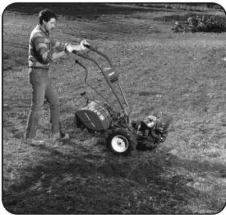
natural_image
Person operating a small plow in a grassy field, no visible text or symbolsFigure 4-5
Choosing Wheel & Tine Speeds
The tiller has four FORWARD wheel/tine speed combinations for handling a variety of tilling tasks and gardening jobs. Experiment with the tine depth, engine speed and wheel/tine speed to determine the combination that provides the best results. Here are some tips:
- Advance the engine throttle lever so the engine has sufficient power.
- When tilling untilled or hard earth, do not set the Depth Regulator too deep. The tiller will buck and the engine will load down.
- You will know your settings are ideal when the tines break-up the soil easily, the engine does not labor and your progress is steady and smooth. See Changing Belt Speed.
WHEEL SPEED & BELT RANGE SELECTION GUIDE
SLOW GEAR, LOW BELT RANGE
For:
- Tilling in sod.
- Tilling in hard clay.
- Tilling under standing cornstalks in tough soil conditions.
- Tilling under cover crops.
- Preparing a deep seedbed.
- Tilling in stony soil.
- Tilling under residues and organic matter.
- Mixing in fertilizers or manure,
SLOW GEAR, HIGH BELT RANGE
For:
- Tilling in sod or hard clay.
- Tilling under standing cornstalks (slow, steady speed allows time to shred stalks).
- Tilling under cover crops (best wheel speed and belt speed range in most soils).
- Preparing seedbeds (best speed choice in most soils).
- Tilling in stony ground.
- Building raised garden beds.
- Mixing in fertilizer.
- Using tiller wings in hard soil.
- Mixing fertilizer and manure.
- Tilling residues and organics.
FAST GEAR, LOW BELT RANGE
For:
- Going over seedbed for the last time before planting crops.
- Covering over seeds in wide row or plot planting (lift handlebars to avoid going too deep).
- Hilling and furrowing.
- Making raised beds.
- Cultivating (lift handlebars to avoid going too deep).
- Tilling large areas.
- Tilling organic matter in.
- Cultivating between raised beds with optional hiller/furrower attachment.
FAST GEAR, HIGH BELT RANGE
For:
- Preparing seedbeds for planting.
- Covering seeds with less need to hold up the handlebars.
- Cultivating (tiller travels faster, rides higher on the soil; allows engine RPM to be reduced; handlebars don't have to be raised).
- Keeping large areas tilled and cultivated in the summer.
- Tilling organic matter under.
- Moving tiller quickly.
- Cultivating between raised beds using the optional hiller/furrower.
Figure 4-6
Changing Belt Speed
Your tiller has two belt-driven speed ranges — HIGH RANGE and LOW RANGE — you pick one or the other by deciding which set of pulley grooves to move the forward belt into. By moving the belt from one speed range into the other, in combination with the FAST and SLOW wheel speeds, you obtain a choice of four different forward wheel speeds and two different tine speeds.

WARNING! To help avoid serious personal injury, stop the engine, remove the ignition key, disconnect spark plug wire, and move the wire away from the spark plug and let engine and muffler cool down before changing the belt speeds.
Changing the belt from LOW range into HIGH range (or back again) is a matter of moving the belt from one set of pulley grooves to a second set of pulley grooves. This change is done quickly and without tools.
When the tiller is moving in REVERSE, the wheels are powered by a rubber reverse disc, not by the belt. Therefore, you have only two reverse speeds SLOW and FAST, as set with the Wheel Speed Lever.
Figure 4-7 shows the range of wheel and tine speeds available when using the two belt speed ranges and the FAST and SLOW selections on the Wheel Speed Lever.
| Available wheel and tine speeds at 3000 RPM engine speed | |||
| Belt Position | Wheel Speed Lever | Wheel Speed | Tine Speed |
| Low Range Slow .5 MPH 146 RPM | |||
| Low Range | Fast | 1.2 MPH | 146 RPM |
| High Range Slow .7 MPH 200 RPM | |||
| High Range | Fast | 1.72 MPH | 200 RPM |
Figure 4-7
Changing Belt From Low Range to High Range
-
To avoid personal injury, shut off the engine, let all moving parts come to a complete stop, then disconnect the spark plug wire from the spark plug and move the wire away from the spark plug before making any adjustments. Wait for the engine and muffler to cool down.
-
Move the Wheels/Tines/PTO Drive Lever into NEUTRAL.

WARNING! The HIGH speed belt range position combined with a FAST wheel speed setting propels the tiller at the fastest pace. Reduce the engine throttle speed when starting out to help avoid personal injury or property damage if using this speed combination.
- Kneel on the left side of tiller. To create belt slack, reach over to the right side of the pulleys and push in at the center of the belt with a finger. At the same time, use your left hand to work the belt part-way onto the lower-front transmission pulley groove. See Figure 4-8.
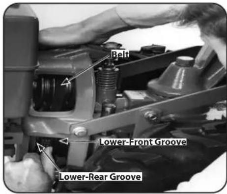
Figure 4-8
- Go to the other side of the tiller to finish seating the belt onto the pulley groove.
- Working from the left side of the tiller, work the belt as much as possible onto the top-front engine pulley groove. See Figure 4-9.
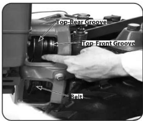
Figure 4-9
- Finish seating the belt from the right side of the tiller.
NOTE: Proper belt tension is important for good performance. See the Service section for instructions on adjusting belt tension.
NOTE: If extra belt slack is needed to move the belt, just raise the Wheels/Tines/PTO Drive Lever up into REVERSE. This lowers the engine pulley and creates more slack.
- Check both sides of the high range pulley grooves to verify that the belt is properly seated.
Changing Belt From High Range to Low Range
- To avoid personal injury, shut off the engine, let all moving parts come to a complete stop, then disconnect the spark plug wire from the spark plug and move the wire away from the spark plug before making any adjustments. Let engine and muffler cool.
- Move the Wheels/Tines/PTO Drive Lever into NEUTRAL.
- Stand on the left side of the tiller. Use your right hand to hold the Wheels/Tines/PTO Drive Lever up into REVERSE position. Use your left hand to move the belt off the top-front engine pulley groove to top-rear engine pulley groove. See Figure 4-10.
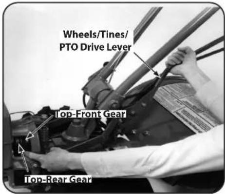
Figure 4-10
- Go to the right side of the tiller and finish seating the belt.
- Still holding the lever up in REVERSE position, and working from the left side of the tiller, move the belt from the lower front transmission groove to the lower rear transmission groove.
- Go to the right side of the tiller and finish seating the belt. See Figure 4-11.
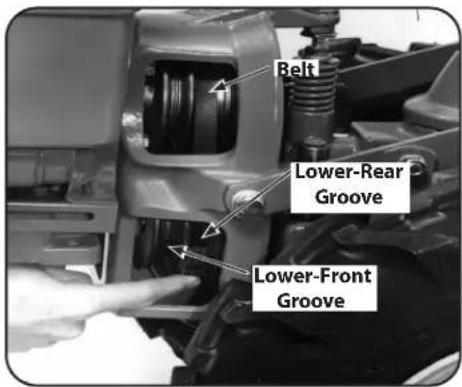
Figure 4-11
- Check that the belt is fully seated in the pulley grooves. Check this from both sides of the tiller.
Clearing the Tines
The tines have a self-clearing action which helps to eliminate most tangling of debris. However, occasionally dry grass, stringy stalks or tough vines may become tangled. Follow these procedures to help avoid tangling and to clear the tines, if necessary.
- To reduce tangling, set the Depth Regulator deep enough to get maximum "chopping" action as the tines chop the material against the ground. Also, try to till under crop residues or cover crops while they are green, moist and tender.
- While power composting, try swaying the handlebars from side to side (about 6" to 12"). This "fishtailing" action often clears the tines of debris.
- It may be necessary to remove the debris by hand (a pocket knife will help you to cut away the material).

WARNING! Before clearing the tines by hand, stop the engine, allow all moving parts to stop, and disconnect the spark plug wire. Failure to follow this warning could result in personal injury.
Tilling Tips & Techniques
Let the Tiller Do the Work
- While tilling, relax and let the wheels pull the tiller along while the tines do the digging. Walk on the side that is not yet finished to avoid making footprints in the freshly tilled soil and lightly, but securely, grip the handlebar with just one hand. Refer to Figure 4-4 on page 9.
- Avoid pushing down on the handlebars in an attempt to force the tiller to dig deeper. Doing so takes the weight off the powered wheels, causing them to lose traction. Without the wheels helping to hold the tiller back, the tines will attempt to propel the tiller — often causing the tiller to skip rapidly across the ground. Sometimes, slight downward pressure on the handlebars will help get through a particularly tough section of sod or unbroken ground, but in most cases this won't be necessary.
Tilling Depths
- Avoid trying to dig too deeply too quickly, especially when busting sod or tilling soil that hasn't been tilled for some time. Use shallow depth settings (only an inch or two deep) for the first passes through the garden area. With each succeeding pass, adjust the depth regulator to dig another inch or two deeper. Watering the garden area a few days prior to tilling will make tilling easier, as will letting the newly worked soil set for a day or two before making a final, deep tilling pass.
- When cultivating — breaking up the surface soil around plants to help destroy weeds — use very shallow depth settings to prevent injury to plants whose roots often grow close to the surface. If needed, lift up on the handlebars slightly to prevent the tines from digging too deeply. Cultivating on a regular basis not only eliminates weeds, it also loosens and aerates the soil for better moisture absorption and faster plant growth.
Avoid Tilling Wet, Soggy Soil
- Tilling wet soil often results in large, hard clumps of soil that can interfere with planting. If time permits, wait a day or two after heavy rains to allow the soil to dry before tilling. Test the soil by squeezing it into a ball. If it compresses too easily, it is too wet to till.
Avoid Making Footprints
- When possible, walk on the untilled side of the tiller to avoid making footprints in the freshly tilled soil. See Figure 4-4 on page 9. Footprints cause soil compaction that can hamper root penetration and contribute to soil erosion. They can also "plant" unwanted weed seeds back into the newly tilled soil.
Suggested Tilling Patterns
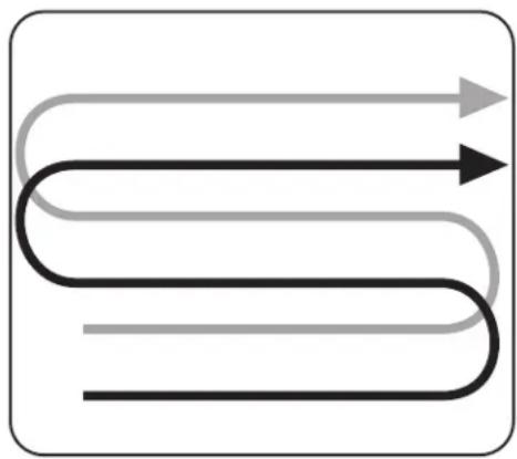
- When preparing a seedbed, go over the same path twice in the first row, then overlap one-half the tiller width on the rest of the passes. See Figure 4-12.
natural_image
Abstract diagram of three curved lines with arrows, no text or symbols presentFigure 4-12
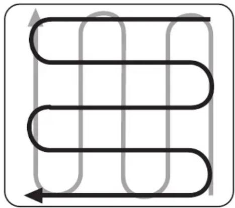
- When finished in one direction, make a second pass at a right angle. See Figure 4-13. Overlap each pass for best results. In very hard ground it may take three or four passes to thoroughly pulverize the soil.
natural_image
Pure diagram of a coiled pipe or tube with directional arrows, no text or symbols presentFigure 4-13
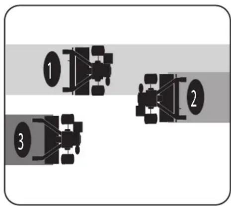
- If the garden size will not permit lengthwise and then crosswise tilling, then overlap the first passes by 1/2 a tiller width, followed by successive passes at 1/4 width. See Figure 4-14.
flowchart
graph TD
    A["1"] --> B["2"]
    B --> C["3"]
Figure 4-14
- With planning, you can allow enough room between rows to cultivate. Leave room for the hood width, plus enough extra room for future plant growth. See Figure 4-15.
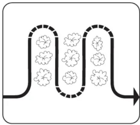
flowchart
graph LR
    A["Stage 1"] --> B["Stage 2"]
    B --> C["Output"]
    style A fill:#fff,stroke:#000
    style C fill:#fff,stroke:#000
    style B fill:#fff,stroke:#000
    style C fill:#fff,stroke:#000
    style D fill:#fff,stroke:#000
    style E fill:#fff,stroke:#000
    style F fill:#fff,stroke:#000
    style G fill:#fff,stroke:#000
    style H fill:#fff,stroke:#000
    style I fill:#fff,stroke:#000
    style J fill:#fff,stroke:#000
    style K fill:#fff,stroke:#000
    style L fill:#fff,stroke:#000
    style M fill:#fff,stroke:#000
    style N fill:#fff,stroke:#000
    style O fill:#fff,stroke:#000
    style P fill:#fff,stroke:#000
    style Q fill:#fff,stroke:#000
    style R fill:#fff,stroke:#000
    style S fill:#fff,stroke:#000
    style T fill:#fff,stroke:#000
    style U fill:#fff,stroke:#000
    style V fill:#fff,stroke:#000
    style W fill:#fff,stroke:#000
    style X fill:#fff,stroke:#000
    style Y fill:#fff,stroke:#000
    style Z fill:#fff,stroke:#000
Figure 4-15
Tilling on Slopes
If you must garden on sloping ground, please follow two very important guidelines:
-
Till only on moderate slopes, never on steep inclines where footing is difficult. Review the safety rules in the Safe Operation Practices section.
-
It is recommended that you till up and down slopes rather than terracing. Tilling vertically on a slope allows maximum planting area and also leaves room for cultivating.
NOTE: When tilling on slopes, be sure the correct oil level is maintained in the engine (check every 1/2 hour of operation). The incline of the slope will cause the oil to slant away from its normal level and this can starve engine parts of required lubrication. Keep the engine oil level at the full point at all times.
Tilling up and down slopes:
• To keep soil erosion to a minimum, be sure to add enough organic matter to the soil so that it has good moisture holding texture and try to avoid leaving footprints or wheel marks.
- When tilling vertically, try to make the first pass uphill as the tiller digs more deeply going uphill than it does downhill. In soft soil or weeds, you may have to lift the handlebars slightly while going uphill. When going downhill, overlap the first pass by about 1/2 the width of the tiller.
NOTE: For the best results, use the HIGH belt range and SLOW wheel speed lever position. See Changing Belt Speed in this section for more information on changing to high range.
Terrace Gardening:
- When a slope is too steep or too short for vertical tilling, it may be necessary to till across the slope and create terraced rows. Terraces are rows that are cut into the side of a slope, creating a narrow, but flat, area on which to plant.
- On a long slope, you can make several terraces, one below the other.
- Terraces should be only 2-to-3 feet wide. Digging too far into the side of the slope will expose poor subsoil that is unproductive for plants.
- To create a terrace, start at the top of the slope and work down. Go back and forth across the first row. See Figure 4-16.
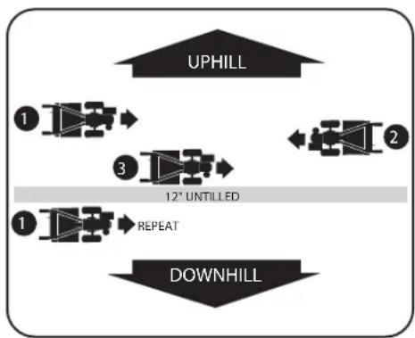
flowchart
graph TD
    A["UPHILL"] --> B["1"]
    B --> C["3"]
    C --> D["12° UNTILLED"]
    D --> E["1"]
    E --> F["REPEAT"]
    F --> G["DOWNHILL"]
Figure 4-16
- Each succeeding lower terrace is started by walking below the terrace you are preparing. For added stability of the tiller, always keep the uphill wheel in the soft, newly tilled soil. Do not till the last 12" or more of the downhill outside edge of each terrace. This untilled strip helps prevents the terraces from breaking apart and washing downhill. It also provides a walking path between rows.
Tilling across slopes without terracing:
- If vertical or terracing gardening aren't practical for you, then you can till laterally across a slope. We do not really recommend this method as it can create unsure footing and invites soil erosion.
- Study the terrain to make certain the slope is not too steep for safe tilling. If possible, make terraced rows or till vertically.
- Move the belt into LOW belt range and the Wheel Speed Gear Lever to SLOW position. As in terrace gardening, start at the top of the slope and overlap the first pass by half the width of the tiller. For added stability, keep the uphill wheel in the soft, newly tilled soil. Each succeeding terraced area is started by walking below the terrace you are preparing. See Figure 4-17.
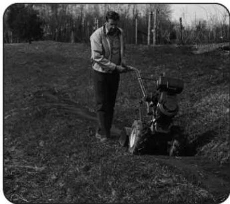
natural_image
Black-and-white photo of a man operating a small tiller in a field, no visible text or symbolsFigure 4-17
Power Composting
Power composting means tilling under and burying in the soil all manner of organic matter such as crop residues, leaves, grass clippings and cover crops. This material will decompose during the non-growing season and add important natural nutrients to the soil.

WARNING! When power composting, do not keep the Depth Regulator Lever at a deep setting if the tiller jumps or bucks. If jumping or bucking occurs, move the Depth Regulator Lever down to one of the shallower settings and then slowly increase the tilling depth on later passes. Failure to comply could result in loss of tiller control, property damage, or personal injury.
- Begin by composting crop residues such as leftover vines, stalks, stems and roots. Power compost these crop residues as soon as they finish bearing. The sooner this is done, the better, as tender green matter is easier to till under. Use the deepest depth regulator setting possible without causing the engine to labor or the tiller to jump ahead.
• Standing cornstalks of reasonable height can be power composted. See Figure 4-18.
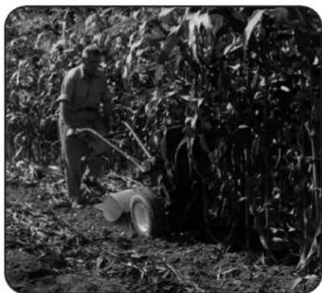
natural_image
Black-and-white photo of a person operating a manual till machine in a cornfield, surrounded by dense foliage (no visible text or symbols)Figure 4-18
- Pushing over (but not uprooting) cornstalks will often make it easier for your tiller to chop up the stalks. Keep the tines clear of excessive tangling by "fishtailing" or frequently using reverse. Make several passes, then return a few days later to finish off any remaining stubble.
• After tilling under crop residues, add more organic matter such as leaves, grass clippings and even kitchen scraps. When tilled into the soil, this organic matter will decompose and add even more important nutrients to the soil.
• After power composting, you may want to plant a "green manure" cover crop to protect the soil during the off-season. Grow a crop of clover, alfalfa, buckwheat, peas, beans, rye grass, grain or kale and then till it into the soil prior to the planting season.
Wide-Row Planting
The wide-row planting technique is spreading seeds anywhere from 10 inches to 2 feet wide or more. As a result, you can grow anywhere from 3 to 4 times (or more) produce in the same space that is normally set aside for an area that has narrow, single rows.
Wide-row planting automatically shades the ground which keeps weed growth down and also holds moisture in the soil. And of course, harvesting is much easier — everything is right at hand to be picked. Preparing wide rows is easy — after you prepare the seedbed and mark off the rows with string, hand-broadcast the seeds as if seeding a lawn — not quite as much as lawn seed. Cover with soil and tamp the area firmly with a hoe.
Tilling Under Corn
After corn is harvested, the stalks should be tilled into the soil while still green. Dry plants are more difficult to till under, and the roots break loose too easily.
NOTE: Do not pull the roots out by hand or cut the stalks before tilling. Stalks that are firmly anchored by their roots are much easier for the tines to chop, cut and work under.
- As you move forward into a row of stalks, aim the tiller so that the stalks go between the left wheel and the transmission case. See Figure 4-18. Do not use the right wheel because damage could occur to the air cleaner, carburetor or throttle linkage.
- Each new pass should overlap the previous pass by one-half the width of the tiller.
- Till as deeply as possible. Pull the Depth Regulator all the way UP and engage the lowest notch for deep tilling. Use either LOW or HIGH belt range and SLOW wheel speed gear position. Let the tilled-in stalks decompose for a week or so. Then till in the remaining residue as deep as possible.
PTO Power Feature
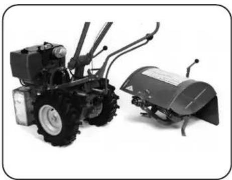
Your tiller is a self-contained PTO (Power Take-Off) Power machine that was shipped with a tine attachment installed. The tine attachment can be quickly removed and replaced with other optional attachments. See Figure 4-19. The following instructions will familiarize you with your PTO Power machine. Please read these pages carefully. The following steps explain how to remove and replace the tine attachment. You will need a 3/4" wrench, minimum 12" long for leverage.
natural_image
Two small agricultural machines: a mobile tiller and a flatbed tractor, shown against a plain white background (no text or symbols visible)Figure 4-19
NOTE: Before operating your PTO Power machine for the first time, make sure that you have read all the safety instructions in the Safe Operation Practices section of this manual as well as the manual supplied with any attachment. Read the controls information and operating procedures for the tiller and engine described in the Assembly & Set-Up and the Controls & Operation sections. Also be sure to read the Engine Operator's Manual.
Removing the Tine Attachment
- Move the tiller to level ground.
- Be sure the engine is stopped, the electric start key is removed and the spark plug wire is disconnected and moved away from the spark plug.
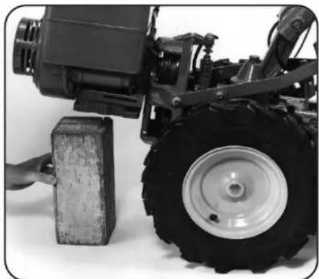
- Place a sturdy support under the engine to prevent the engine from tipping forward when the tine attachment is removed. See Figure 4-20.
natural_image
Close-up of a small mechanical vehicle with a rubber block and large tire, no visible text or symbolsFigure 4-20
- Place the Wheels/Tines/PTO Drive Lever into NEUTRAL.
- Place Tines/PTO Clutch Lever in DISENGAGE.
-
Place Wheel Speed Lever into FREEWHEEL.
-
Loosen the two swing-out bolts that connect the power transmission to the tine attachment. See Figure 4-21.
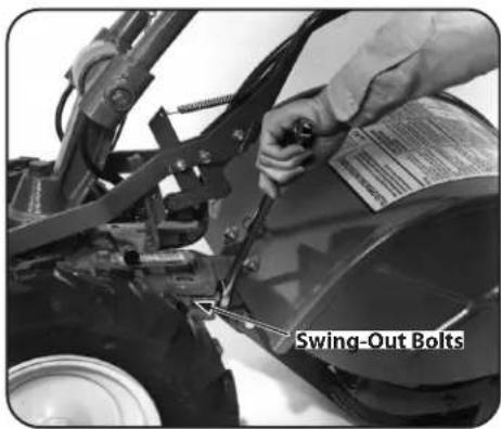
Figure 4-21
- Then move the swing-out bolts out. See Figure 4-22.
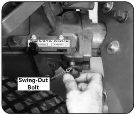
Figure 4-22
NOTE: Loosening swing-out bolts can be difficult. Use an extra-long wrench for leverage.
- Tip the PTO power machine forward about one inch with one hand while pulling the tine attachment back. See Figure 4-23.
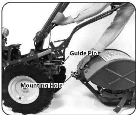
Figure 4-23
- The guide pin on the power unit will slide out of the guide hole in the tine attachment. See Figure 4-24.

Figure 4-24
Installing the Tine Attachment
- Move the two PTO Power Unit swing-out bolts outward and slide the washers up against the bolt heads.
- Remove the support block from under the engine and slowly roll the power unit back next to the tine attachment. Place the support block back under the engine.
- Remove the dust cap (or protective wrapping) from the dog clutch coupling on the tine attachment.
- Carefully align the guide pin on the PTO Power Unit with the alignment hole in the tine attachment and bring the two units together. See Figure 4-24.
- Move the two swing-bolts into the slots of the tine attachment. Alternately tighten each bolt until they are tight enough to make the concave washers flat. The bolts must be very tight — if you have a torque wrench, tighten each bolt to between 70 and 80 ft-lbs.
NOTE: The swing-bolts must be kept very tight to prevent damaging wear to the dog clutch coupling, alignment pin or the alignment hole. Check the bolt tightness every 2-1/2 operating hours. - Remove the engine support before moving the tiller in a forward direction.
Moving the Tiller
When the engine is running, the tiller's powered wheels make moving the tiller to and from the garden easy. If the engine is not running, set the Wheel Speed Lever to FREEWHEEL position to roll the tiller to another location.

WARNING! To help avoid personal injury from revolving tines, always put the Tines/PTO Clutch Lever in DISENGAGE position before transporting, loading, or unloading tiller.
- Place the Tines/PTO Clutch Lever in DISENGAGE position.
- Move the Depth Regulator Lever down all the way into the TRAVEL setting.
- If using engine power, move Wheel Speed Lever to either SLOW or FAST, and use the Wheels/Tines/PTO Drive Lever to drive the wheels.
- If the engine is stopped, move Wheel Speed Lever to FREEWHEEL and manually push the tiller.
Loading & Unloading the Tiller
The following provides information on tiller loading, unloading and requirements before loading and unloading the tiller. Read the following instructions carefully before attempting to load or unload your tiller.
Follow these steps before loading or unloading the Tiller:
- Ramps must be strong enough to support the combined weight of the tiller and the operator. They should provide good traction to prevent slipping; they should have side rails to guide the tiller along the ramps; and they should have a locking device to secure them to the vehicle.
- Operators should wear sturdy footwear that will help to prevent slipping.
- Turn the vehicle's engine off and apply its parking brake.
- Position the loading vehicle so that the ramp angle is as flat as possible (the less incline to the ramp, the better).
Loading the Tiller
- Use loading ramps that are strong and wide enough to safely hold the weight of the tiller and the operator combined — your tiller weighs between 280 and 325 lbs.
- Move the Tines/PTO Clutch Lever into DISENGAGE position.
- Set the Depth Regulator Lever to the TRAVEL position.
- Move Wheel Speed Lever into SLOW position and reduce the engine throttle speed.
- Shift the Wheels/Tines/PTO Drive Lever into FORWARD position and follow the tiller up the ramps. Check the wheels as you move the tiller forward. Ensure that they move up the center of each ramp.
- Prevent the tiller from rolling in the vehicle. Leave Wheel Speed Lever in FAST or SLOW position, chock the wheels with blocks and tie down the tiller.
Unloading the Tiller
NOTE: Never unload the tiller in FORWARD drive. The tiller could tip forward and expose you to the tines (which should be disengaged as instructed).
- Use loading ramps that are strong and wide enough to safely hold the weight of the tiller and the operator combined — your tiller weighs between 280 and 325 lbs.
- Move the Tines/PTO Clutch Lever to DISENGAGE position.
- Set the Depth Regulator Lever to the TRAVEL position.
- Move Wheel Speed Lever to SLOW position and reduce the engine throttle speed.
NOTE: Look behind you before you back down the ramp to ensure that all is clear. While descending, keep checking for obstacles behind you. - Move and hold the Wheels/Tines/PTO Drive Lever into REVERSE drive and back down the ramps. Check the wheels as you move the tiller backward. Ensure that they move down the center of each ramp.
Maintenance Schedule
| After 2-hour Break-In | Before Each Use | Every 10 Hours Every | 25 Hours Every 30 Hours | Hours | Refer to Engine Manual | |
| Check Engine Oil Level | √ | |||||
| Clean Engine Cooling System | √ | |||||
| Test Operation of FWD. Interlock Safety System | √ | |||||
| FWD. Interlock Safety System — Check Wire Condition/Connections | √ | √ | ||||
| Check Electrical Connections | √ | |||||
| Recharge Battery | ||||||
| Check Drive Belt Tension | √ | √ | ||||
| Check Nuts and Bolts | √ | √ √ | ||||
| Clean Tiller Tine Shaft | √ | √ | ||||
| Lubricate Tiller | √ | √ | ||||
| Check Gear Oil Lever in Both Transmissions | √ | √ √ | √ | |||
| Check Bolo Tines for Wear | √ | |||||
| Check Reverse Disc for Wear | √ | |||||
| Check Air Pressure in Tire | √ |

WARNING! Before inspecting, cleaning, or servicing the tiller, shut off the engine and wait for all the parts to come to a complete stop. Disconnect the spark plug wire and move the wire away from the spark plug. Remove the ignition key on electric start models. Failure to follow these instructions can result in serious personal injury or property damage.
Maintenance
Engine
Refer to the Engine Operator's Manual packed with your machine for all engine maintenance.
Tire Pressure
Check the air pressure in both tires every 30 operating hours. Deflate or inflate both tires evenly to 15- to 20-PSI (pounds per square inch).
Be sure that both tires have the same air pressure or the tiller will tend to pull to one side.
Battery

WARNING! When removing the battery, always disconnect the negative (-) cable first followed by the positive (+) cable. Reverse this procedure when reinstalling the battery.
The battery is sealed and is maintenance free. Acid levels cannot be checked.
• Always keep the battery cables and terminals clean and free of corrosive build-up.
• After cleaning the battery and terminals, apply a light coat of petroleum jelly or grease to the terminals and cover both terminals with the rubber boots.
Tine Shaft
After every 10 operating hours, remove the left- and right-side Bolo Tine holders and clear away dirt and debris that have accumulated on the tine shaft or inside the tine holders. Please follow this maintenance recommendation, as debris can cause premature wear to the tine shaft and its oil seals. Refer to the previous tine holder removal instructions. After cleaning away any debris and removing old grease from the tine shaft, apply fresh grease to the tine shaft.
Wheel Shaft Maintenance
After every 10 operating hours, remove the wheels and clear away dirt and debris that has accumulated on the wheel shaft. Please follow this maintenance recommendation, as debris can cause premature wear to the wheel shaft and its oil seals.
- Prop the transmission up with a sturdy block to raise the wheels off the ground.
-
Remove the wheels by removing the hex bolt and lock nut which secures each to the wheel shaft.
-
After cleaning away any debris and removing old grease, apply fresh grease to the wheel shaft before re-installing the wheels.
Hardware
Check for loose or missing hardware every ten (10) operating hours. Failure to tighten or replace fasteners can cause poor performance, equipment damage or oil leakage. Most hardware on your tiller is visible. Pay particular attention to hardware listed below.
Transmission Pulley Mounting Bolt
- If the washer behind the bolt head is loose, the bolt needs tightening. To do this, first insert a punch or thick screwdriver into the hole next to the bolt and wedge the tool against the side of the motor mount casting. This immobilizes the pulley while you tighten the bolt. See Figure 5-1.
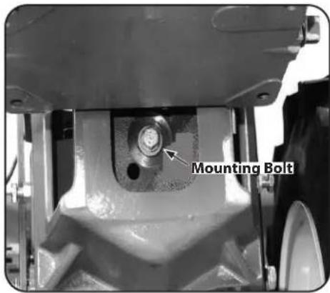
Figure 5-1
Neutral Plunger Assembly Jam Nut
• The jam nut is located on the left side of the neutral plunger. If loose, immobilize bolt head with one wrench and use another wrench to tighten the nut. See Figure 5-2.
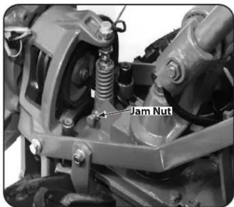
Figure 5-2
Rear Bearing Cap Screws
• The three rear bearing cap screws are located under the depth regulator mounting bracket. If any are loose, it can cause an oil leak or drive shaft end play. See Figure 5-3.
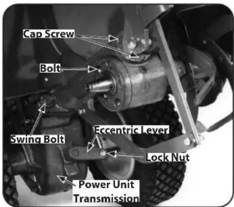
Figure 5-3
Housing Cover Bolts
- Check the five bolts securing the tiller housing cover to the left side of the transmission. Gear oil can leak from a loose housing cover. To reach the bolts, remove the left side tine holder. See Tines in the Service section.
Swing Bolts
- Check both of the swing-bolts that connect the power unit transmission to the tine attachment. Both bolts should be checked every 2-1/2 hours of operation. If loose, wear can occur on the locating pin on the power unit, and cause enlargement of the locating hole in the tine attachment. Using a torque wrench, tighten these bolts to 70-80 ft-lbs.
Lock Nut on the Shifting Linkage
- Check the locknut that fastens the shifting linkage to the eccentric shifting lever. See Figure 5-3. Do not tighten the locknut against the eccentric lever. It should be very close to, but not touching the lever.
Tine Hardware
- Check the four bolts and nuts securing left and right tine holders to the tine shaft. See Figure 5-4.
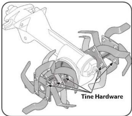
Figure 5-4
Transmission Gear Oil
Checking for oil leaks
- At 25-hour operation intervals, check the tiller for oil leaks. Inspect for oil accumulations on the tiller or the floor where it is stored.
- A small amount of oil seepage or wetness around a shaft opening or cover is no cause for alarm. But a heavy concentration of oil is more serious. You should tighten all bolts immediately, and replace any worn seals or gaskets.
- It may be impossible to determine how much oil has been lost, so check the oil levels in the PTO transmission and the tine attachment before using the tiller again. Add any necessary gear oil. Serious damage to the transmission components can result from operation when gear oil levels are low.
- If tilling during very hot weather, the gear oil may heat up and expand inside the transmissions. To allow for this oil expansion, both the power unit transmission and the tine attachment transmissions have oil relief vents. See Figure 5-5.
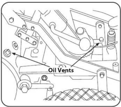
Figure 5-5
• The vents allow small amounts of oil to seep out.
• If a serious leak is discovered, please contact your authorized dealer or the Troy-Bilt Technical Service Department for service advice.
Checking Gear Oil Levels
Every 30 hours of operation, check the gear oil level in both the power unit transmission and the time attachment transmission. Operating them while low on gear oil — even briefly — can cause serious damage to internal components.
- The transmissions must be cool, since hot gear oil expands and gives a false reading.
- The power unit transmission and the tine attachment transmission must be connected when checking — or adding — gear oil.
-
Move the tiller to level ground. Move the Depth Regulator Lever up so the tines rest on the ground.
-
Use a 3/8" wrench to remove the oil level check plug on the left side of the transmission housing. See Figure 5-6.
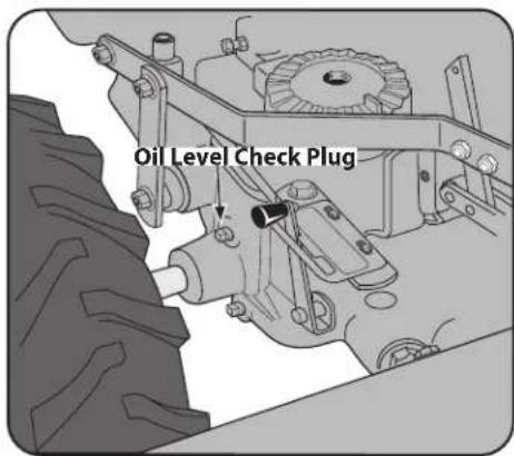
Figure 5-6
- If the oil level is correct, oil will seep out of the check hole (allow extra time in cold weather). If it does, the level is fine and you should replace the check plug. If no oil seeps out add oil as demonstrated in the Adding or Changing Gear Oil section.
Tine Attachment Oil Level
NOTE: Two different gear oil checking procedures for the tine attachment transmission are described next. Use the first procedure if the dipstick in your tine attachment has only a 'Check Cold' marking. Use the second procedure if the dipstick has both cold and hot markings at the end. First remove the dipstick from the tine attachment transmission to see which type of dipstick you have. See Figure 5-7. Then replace the dipstick with the markings on the dipstick facing to the rear.
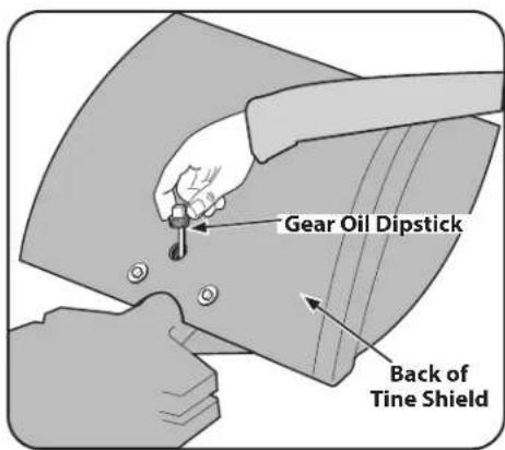
Figure 5-7
For Dipsticks with 'Check Cold' Marking (Cold means 2 hours have passed since the tiller was used.)
- Move the tiller to level ground.
- Pull the Depth Regulator Lever back, then push it down all the way (to engage its top notch).
- Place a sturdy support under the engine to prevent the tiller from tilting too far.
- Now slide three pieces of 2" x 4" lumber underneath the drag bar — raising the drag bar about 4-1/2" above ground. This elevation allows an accurate "cold" gear oil reading.
-
Wait two hours with tiller elevated (allow more time if temperature is below 40^ F ( 4.4^ C).
-
Loosen and remove the transmission dipstick on the back of the tine shield. See Figure 5-7. Wipe it clean with a rag.
- Hold the dipstick so its markings face to the rear of tiller. Lower it straight down into the sump hole to touch the drive shaft inside. See Figure 5-7. Don't force or try to thread it back in; an incorrect reading will result.
- Remove the dipstick and check the oil level. It should be anywhere within the crosshatched area or even slightly above the Max marking. If correct, replace the dipstick and remove the boards used as props.
- If the oil level was low, gear oil must be added before using the tiller. See Adding or Changing Gear Oil.
For Dipsticks With Hot/Cold Markings
- Move the tiller to level ground.
- Pull the Depth Regulator Lever back, then push it down all the way (to engage its top notch).
- Place a sturdy support under the engine to prevent the tiller from tilting too far.
- Cold reading (preferred method): (Two hours have passed since the tiller was used.) Place a 2" x 4" board (on edge) under the drag bar — raising the tiller and drag bar about 3-1/2" above ground. Hot reading: (Tiller was operated for more than 30 minutes within the past hour.) Do not use the wood prop to elevate the tiller.
- Follow Steps 4, 5 and 6 in the For Dipsticks with 'Check Cold' Marking section.
- Remove the dipstick and check the level. It should be within or above the "Cold" range marking if taking a cold reading. If taking a hot reading, the level should be within or slightly above the "Hot" range.
- If the level is incorrect, see Adding or Changing Gear Oil.
Adding or Changing Gear Oil
For partial fill-ups (just a few ounces or less), use SAE 140, SAE 85W-140, or SAE 80W-90 weight gear oil with an API rating of GL-4 or GL-5. For full replacement, use SAE 140 or SAE 85W-140 gear oil with an API rating of GL-4 only. (At the factory, SAE 85W-140 weight gear oil is used.)
NOTE: Do not use automatic transmission fluid or engine oil. They are too light in weight and will result in transmission damage.
NOTE: The gear oil does not need to be changed. Do so only if you know, or suspect, it is contaminated with dirt, sand or other foreign particles.
Gear oil is available at authorized dealers and most service stations, power equipment centers or farm/heavy equipment outlets.
Capacities: The Power Unit transmission holds approximately 60 ounces and the Tine Attachment transmission holds approximately 12-1/2" ounces.
Adding Gear Oil to the PTO Power Unit Transmission
-
Do Steps 1-4 of Checking Gear Oil Levels.
-
Using a 3/4" wrench (or socket), remove the bolt securing the handlebar base to the top of the transmission (prop the handlebars first to prevent them from falling). Then, unplug the Forward Interlock wire harness receptacle at the bottom of the handlebars. Set the handlebar base and bolt aside on a clean surface. The bolt hole in the top of the transmission is the gear oil fill hole. See Figure 5-8.
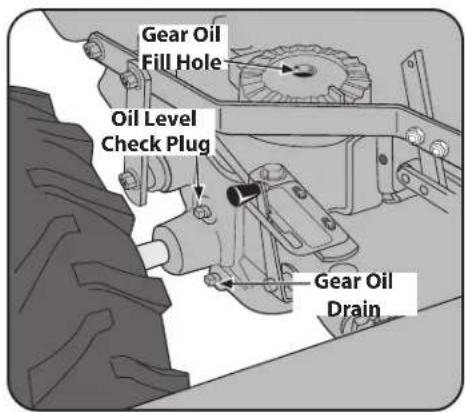
Figure 5-8
- Slowly pour gear oil through a clean funnel into the transmission. Stop when gear oil begins to flow from the oil level check hole on the left side of the transmission. See Figure 5-8.
- Reinstall the oil level check plug. Tighten it securely.
- Reinstall the handlebars using the mounting bolt previously removed. Align the handlebars so they point straight backwards, not at an angle. Then tighten the mounting bolt securely.
- Reconnect the Forward Interlock wire harness to the receptacle. Be certain it is secure.
- Test the operation of the Forward Interlock Safety System. See Forward Interlock System on the next page.
- Place a shallow pan under the transmission gear oil drain plug. See Figure 5-8.
- Remove the oil level check plug with a 3/8" wrench. This vents the transmission for faster oil draining.
- Using the 3/8" wrench, remove the drain plug. The gear oil will drain quite slowly since it is thick. After about two quarts have drained, tilt the tiller forward so any oil at the rear of the transmission will drain out.
- Clean the drain plug threads, put non-hardening gasket sealant on the threads and reinstall the plug.
- Refill the transmission with the correct amount of gear oil before operating the tiller again. When oil seeps from the oil level check hole, the right amount of gear oil has been added. Replace all plugs.
Draining and Filling the PTO Power Unit Transmission
Adding Gear Oil to the Tine Attachment Transmission
- Select the right Depth Regulator Lever setting:
a. If filling an empty transmission, raise the Depth Regulator Lever so tines are on the ground.
b. If topping off the gear oil, move Depth Regulator Lever down to engage its top notch.
- Remove the dipstick from the tine attachment. See Figure 5-6 on page 17.
- Slowly add gear oil in the dipstick hole. Add 1/2-ounce at a time to avoid overfilling. It takes about 12-1/2 ounces.
- Take dipstick readings frequently. Stop when oil reaches "Cold" range marking on dipstick. Replace dipstick securely.
Draining and Filling the Tine Attachment Transmission
- The tine attachment transmission is not equipped with an oil drain plug. To drain just a small amount of gear oil, remove the dipstick and tilt the attachment forward, first uncoupling it from the Power Unit.
- For complete drainage, remove the left-side tine assembly (see Tines in the Service section), then remove just one of the lower screws from the tiller housing cover. See Figure 5-9. To speed drainage, remove the tine attachment dipstick to vent transmission.
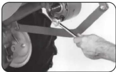
natural_image
Close-up of a hand using a tool to adjust or install a mechanical component (no visible text or symbols)Figure 5-9
NOTE: If you find a plastic washer on the cover screw you removed, discard the washer. There is no need to install a replacement washer.
- Once all the gear oil has drained, reinstall the housing cover screw securely (first coat its threads with non-hardening gasket sealant).
- Be certain to refill the transmission with the correct amount of gear oil before operating the tiller again.
Forward Interlock System
The wiring circuit for the Forward Interlock System is designed to ground out the engine's ignition system.
There are three switches in the circuit which, when open, let the engine run. One switch is on the neutral plunger tab of the cast iron motor mount. This switch is open whenever the Wheels/Tines/PTO Drive Lever is in NEUTRAL or REVERSE positions. The other two switches are located inside the handlebars, directly above the two Forward Interlock Levers. The switches are wired so when squeezed (open) the engine will run. There is a fourth switch located in the wiring harness connector on the top, right side of the transmission cover. It warns you if the connection is not mated by not letting the engine run while the Wheels/Tines/PTO Drive Lever is in FORWARD.
- A broken or disconnected wire could let the engine run without you having to press one of the Forward Interlock Levers.
- A bare wire touching the tiller or engine metal could ground out the engine's ignition.
- A switch that has failed allows the engine to run. Or it may prevent the engine from running.
Lubrication
Proper lubrication of the tiller's mechanical parts is an essential part of good maintenance. Lubrication should be done after every ten (10) hours of operation.
Use ordinary motor oil (#30 weight or lighter) where oil is specified. Use a quality grease with a metal lubricant where grease is recommended (regular grease is acceptable). Do not over lubricate. If there is a build-up of dirt, remove the build-up and re-apply oil or grease.
NOTE: Do not allow oil or grease to contact the pulleys, drive belt or reverse disc. This can cause the belt or disc to slip on the pulleys.
Lubricate the tiller as follows:
- Oil the wheel shaft between the wheel hubs and the transmission housing. See Figure 5-10.
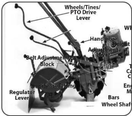
Figure 5-10
- Oil all pivoting and connecting points on the Wheels/Tines/PTO Drive Lever and the Wheel Speed Lever. See Figure 5-10.
- Grease the face of the belt adjustment block. See Figure 5-10.
- Oil the Depth Regulator Lever, including the spring in the mounting bracket. See Figure 5-10.
- Oil the full length of the throttle cable casing. Oil threads on Handlebar Height Adjustment Lever. See Figure 5-10.
- Grease the left- and right-side engine mounting bars at the top, middle and bottom. See Figure 5-10.
-
Grease the zerk grease fitting located on the pivot point at the end of the Wheel Speed Lever. See Figure 5-10. If the Wheel Speed Lever has a grease fitting on the pivot assembly, apply 2-to-3 strokes of multipurpose grease at beginning and end of tilling season.
-
Keep the PTO access area well-greased. See Figure 5-11. If the Tines/PTO Clutch Lever becomes hard to move, squirt some oil into its access hole, and work it back and forth to disperse the oil.
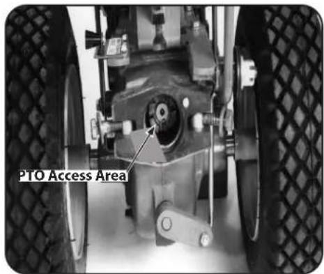
Figure 5-11
Adjustments
Drive Belt
On a new tiller (or if a new belt is installed), the belt tension will probably need to be adjusted after the first two (2) hours of operation. Thereafter, check the belt tension every ten (10) operating hours.
Maintaining the right tension is important to good tiller performance and long belt life. If too loose, the belt will slip on the pulleys, and be unable to deliver full power to the wheels and tines. A loose belt will also wear prematurely.
While checking the belt tension, also inspect the belt for cuts, cracks, deterioration, etc. Don't continue using a belt that isn't in good shape. You're sacrificing tiller performance by doing so.
Tips on keeping the drive belt in top condition include:
• Always put the Wheels/Tines/PTO Drive Lever in NEUTRAL when the tiller is not in use.
- Keep the tension adjusted correctly.
- Don't "speed shift" when moving the Wheels/Tines/PTO Drive Lever between FORWARD and REVERSE.
How to Measure the Belt Tension
- Before taking a measurement, be sure the linkages and pivot points on the Wheels/Tines/PTO Drive Lever are clean and lubricated. If there is any binding, you will not get true measurements. Also, you will need the belt adjustment tool you received with your new tiller. See Figure 5-12.
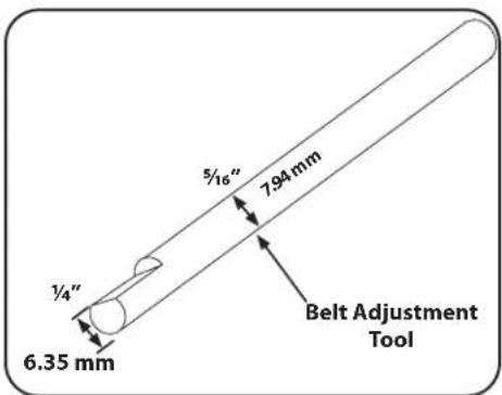
Figure 5-12
- Move the Wheels/Tines/PTO Drive Lever fully down to the FORWARD position. The clutch roller at the bottom of the lever should be positioned underneath the belt adjustment block. See Figure 5-13. Don't let the clutch roller move during the next few steps. If it moves, you'll get a false belt tension reading.

Figure 5-13
- The belt tension is correct if the front of the clutch roller is 1/4"-5/16" away from the face of the upright bracket that holds the adjustment block in place. See Figure 5-13. To measure this distance:
a. Without moving the clutch roller, try inserting the 1/4" -thick, slotted end of the belt adjustment tool in between the roller and the upright bracket. The flat edge of the tool must be facing the roller. See Figure 5-14.
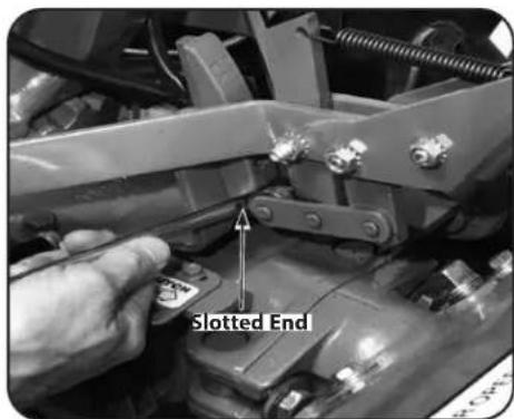
Figure 5-14
b. If only the slotted portion of the tool will fit, the belt tension is correct.
c. If the slotted part of the tool will not fit in, the belt is too loose.
d. If the full thickness (5/16") of the tool easily fits in, the belt is too tight.
- If the belt tension is correct, move the Wheels/Tines/PTO Drive Lever back to NEUTRAL.
How to Adjust the Belt Tension
- As described in the following steps, the drive belt tension is adjusted by moving the adjustment block up or down. Moving it down will tighten the belt; moving it up loosens the belt.
NOTE: The distance the block moves approximately equals the distance the roller moves. In most cases, the clutch roller will not have been very far out of position, so the adjustment block will only need to be moved slightly (up or down).
- Move the Wheels/Tines/PTO Drive Lever to NEUTRAL position. The clutch roller will come to rest anywhere on the face of the belt adjustment block, depending upon drive belt length and current belt tension adjustment.
- Insert the belt adjustment tool through the hole in the side of the adjustment block, spacing the ends of the tool equally on both sides. See Figure 5-15. Rotate the tool so the slotted end faces down.
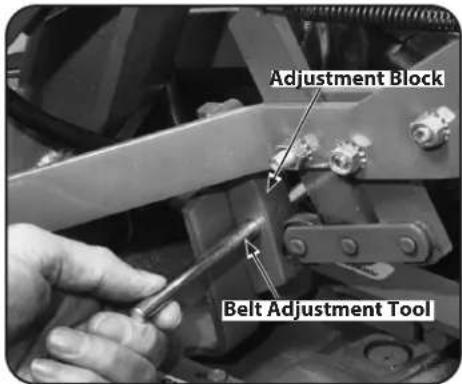
Figure 5-15
- Place the Wheels/Tines/PTO Drive Lever in FORWARD position. The arms of the clutch control yoke will be resting on the belt adjustment tool and the clutch roller should be engaged slightly beneath the adjustment block. See Figure 5-16.
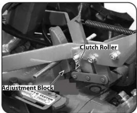
Figure 5-16
- Use one hand to hold the Wheels/Tines/PTO Drive Lever in FORWARD while using a 916" wrench to loosen — do not remove — the bolt at the back of the belt adjustment block. See Figure 5-17. The adjustment block should be free to move either up or down.
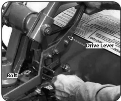
Figure 5-17
- Push the drive lever down if the belt needs tightening. Pull the lever up if the belt needs to be loosened. Hold the drive lever in place and tighten the bolt in the adjustment block firmly.
- Let go of the drive lever and remove the belt adjustment tool from the hole in the adjustment block.
- Check the tension on the belt by following the previous instructions in How to Measure the Belt Tension section.
NOTE: If the adjustment block is all the way down and the measurement between the clutch roller and the bracket is less than 1/4", then a new drive belt is needed.
Reverse Drive System
These instructions explain how to inspect and adjust the various reverse drive components.
But first, here's how the reverse drive system works. When you raise the Wheels/Tines/PTO Drive Lever up in REVERSE position, this lowers the rubberized reverse disc — it is attached to the engine drive pulley — until this rotating disc contacts the transmission drive pulley. The friction between the rotating reverse disc and the transmission pulley causes the transmission drive shaft to be powered in a counter-clockwise direction — as viewed from the operator's position behind the handlebars. The drive shaft then turns the wheels and tine shafts in a reverse direction.
The reverse disc is made of steel with a special, long-lasting rubber compound bonded to the disc rim. Since this is a wearing part, it should be inspected after every 30 operating hours.
- Measure the width of the outside edge of the disc as shown in Figure 5-18. Replace the disc before the rubber edge wears to a thickness of 1/8" or less. Failure to do so could cause the steel underneath the rubber to damage the transmission pulley.
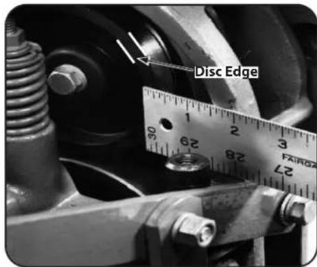
Figure 5-18
- Look for big cracks or missing chunks of rubber from the disc. If so damaged, the disc should be replaced immediately. See the Service section of this manual for instructions on replacing the disc.
NOTE: Extend the life of the reverse disc by always pausing in NEUTRAL before shifting between FORWARD and REVERSE. Also, the reverse disc is not suited for continuous or sustained reverse operation. Use reverse sparingly.
Checking and Adjusting the Reverse Drive System
When the Wheels/Tines/PTO Drive Lever is moved up into REVERSE, the engine and engine mount move down to press on the reverse adjustment bolt. See Figure 5-19.
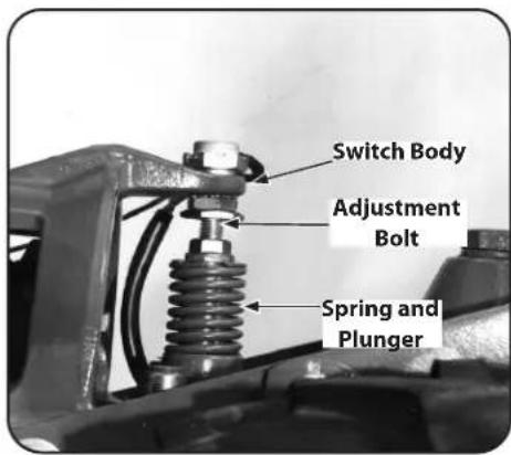
Figure 5-19
This action compresses the reverse spring and plunger assembly, requiring you to hold the lever up in REVERSE. When you release the lever, the spring automatically pushes the lever back into NEUTRAL position.
The spring and plunger assembly is designed to prevent the reverse disc from making contact with the transmission pulley until you shift into REVERSE. When the lever is in NEUTRAL, the switch body on the bottom of the engine mount tab should be resting squarely on top of the reverse adjustment bolt. See Figure 5-19. The reverse adjustment bolt can be adjusted up or down to correct a number of reverse drive operating problems, as explained next.
Checking and Adjusting the Reverse Disc
- Verify that the linkages for Wheels/Tines/PTO Drive Lever are lubricated with oil and engine mount bars and belt adjustment block are lubricated with grease. See Lubrication earlier in this section.
- Place Wheels/Tines/PTO Drive Lever in NEUTRAL. Briefly pull out the engine recoil starter handle while watching the reverse disc. The disc should turn, but lower pulley should not. See Figure 5-20. If the reverse disc turns the lower pulley, or if it is located closer than 3/16" to the pulley, reverse adjustment bolt should be adjusted upward. Moving the adjustment bolt upward will also solve the problem of a tiller that goes into REVERSE on its own.
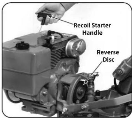
Figure 5-20
- Use your left hand to hold the Wheels/Tines/PTO Drive Lever up in REVERSE, while briefly pulling out the engine recoil starter. The reverse disc should turn the lower pulley. See Figure 5-21. If not, or it requires a lot of pressure to hold the lever up in REVERSE, then the reverse adjustment bolt must be adjusted downward. When correctly adjusted, the Wheels/Tines/PTO Drive Lever should pop out of reverse when the lever is released, but not require exceptional effort to hold it up in the reverse position.
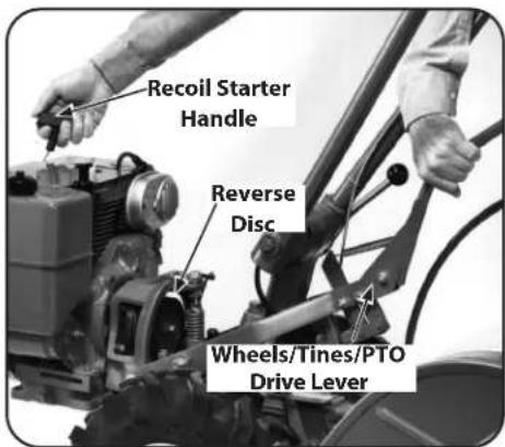
Figure 5-21
- Shift the Wheels/Tines/PTO Drive Lever to REVERSE and then let it go. The lever should return to NEUTRAL. If not, the reverse adjustment bolt will have to be adjusted upward.
Adjusting the Reverse Drive:
- Place the Wheels/Tines/PTO Drive Lever in FORWARD position.
- On the left side of the tiller, put a 1/2" wrench on the plunger retaining bolt and another 1/2" wrench on the jam nut next to it. See Figure 5-22.
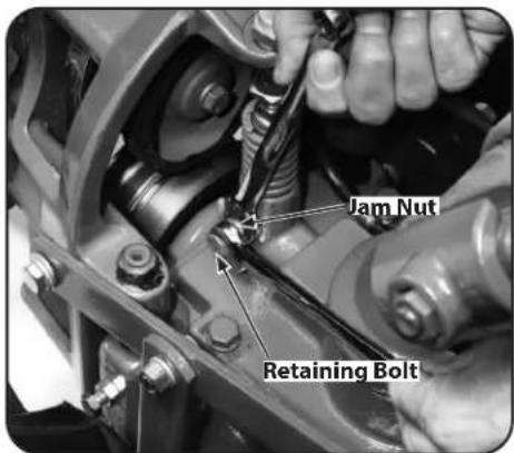
Figure 5-22
- While holding the bolt steady, loosen the jam nut (counter-clockwise) until it touches the bolt head.
-
Turn the bolt in until it tightens against the plunger inside the spring. The bolt must be tight to prevent the plunger from turning — be careful not to overtighten and break the bolt.
-
Place a 7/8" wrench on the head of the reverse adjustment bolt and a 9/16" wrench on the jam nut below it. See Figure 5-23. Hold the bolt steady while loosening the jam nut three or four turns.
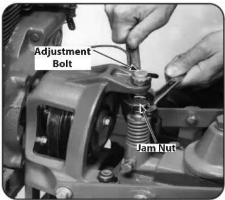
Figure 5-23
- Move the Wheels/Tines/PTO Drive Lever to NEUTRAL. The switch body on the bottom of the engine mount tab should be resting squarely on top of the reverse adjustment bolt, and the reverse disc should be at least 3/16" away from the transmission drive pulley. See Figure 5-19. If the reverse disc is any closer than this, raise the reverse adjustment bolt (turn it counter-clockwise).
- Check that the reverse disc is at least 3/16" away from the transmission drive pulley. Then hold the reverse adjustment bolt steady with one wrench while tightening the jam nut with a second wrench. See Figure 5-23.
- Place a chalk or pencil mark on the top edge of the plunger retaining bolt. Now, while watching the mark, loosen the bolt 3/4-turn. See Figure 5-24. Do not exceed a 3/4 turn. This would disengage the bolt from the locking groove in the side of the plunger.
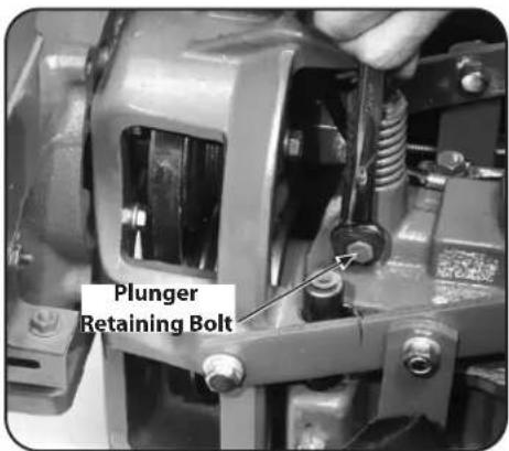
Figure 5-24
- Hold the plunger retaining bolt steady with a wrench while tightening the jam nut against the side of the plunger housing. See Figure 5-22.
- Check the action of the reverse disc as explained previously.
NOTE: If the above adjustments have not corrected an improperly working reverse drive, contact an authorized dealer or the Troy-Bilt Technical Service Department for assistance.
Throttle Cable
The throttle lever settings are factory adjusted, so unnecessary adjustments should not be made. However, if the engine does not start or stop, or respond immediately to various throttle lever settings, then adjustments may be necessary. Please refer to the Engine Operator's Manual supplied with your tiller for specific adjustment instructions.
Ignition System
Your engine is equipped with an electronic ignition. It does not have a condenser or points, so there is no need to perform any regular tune-up maintenance on this system other than adjusting or replacing the spark plug.
Spark Plug
- The spark plug must be in good condition for proper engine operation. Remove and inspect the plug every 50 operating hours or annually, whichever occurs first. The correct electrode gap is .030". Check the gap with a feeler gauge. Do not use a spark plug if the porcelain is cracked, the electrodes are pitted or burned or if other visible damage is present.
NOTE: Do not wire brush or sandblast the spark plug to clean it — loose particles can enter the engine, causing damage. To replace the plug, first tighten it securely by hand, then use a spark plug wrench to tighten the plug an extra 1/4 turn.
Off-Season Storage
When your tiller will not be used during the off-season, prepare it for storage with the following steps:
- Clean the tiller and the engine.
- Do routine tiller lubrication and check for loose hardware.
- Protect the engine from deterioration or damage by referring to the engine storage instructions in your Engine Operator's Manual.
-
When engine is still warm, drain oil from engine crankcase. Refill with fresh motor oil.
-
Protect the internal cylinder against rust by removing the spark plug and pouring one ounce of clean engine oil into spark plug hole. Then slowly pull out the recoil start rope 2 or 3 times to distribute the oil internally. Replace spark plug, but do not reconnect the plug wire. Pull the rope until resistance is felt — let rope rewind.
-
Charge the battery (electric start option). Store the battery in cool, dry location.
-
Move the Wheels/Tines/PTO Drive Lever to NEUTRAL position. Keep the tiller in a clean, dry area.
-
Never store the tiller with fuel in the fuel tank in an enclosed area where gas fumes could reach an open flame or spark, or where ignition sources are present (space heaters, hot water heaters, furnaces, etc.).
Belt Replacement
Drive Belt
-
Move the Wheels/Tines/PTO Drive Lever to NEUTRAL position.
-
While kneeling on the right side of the tiller, create slack in the belt by reaching over to the left side of the pulleys and pushing in on the center of the belt with your finger.
- Use your right hand to move the belt down and away from the lower pulley, in the direction of the engine. See Figure 5-25.
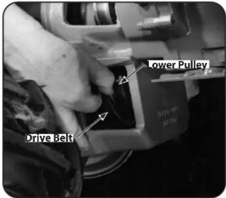
Figure 5-25
- Push the belt upward to create slack in the belt. See Figure 5-26.
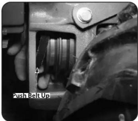
Figure 5-26
- Lift the top half of the belt up and over the upper pulley and the rubber reverse disc, moving it in front of the reverse disc. See Figure 5-27.

Figure 5-27
- Push the Wheels/Tines/PTO Drive Lever down into the FORWARD position. This increases the distance between the upper and lower pulleys. Next, lift and pull the entire belt out from between the pulleys. See Figure 5-28.
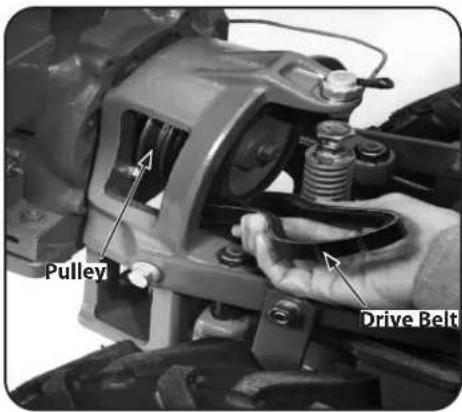
Figure 5-28
- Place the Wheels/Tines/PTO Drive Lever in FORWARD position.
- Squeeze the belt in the middle and insert one end in between the pulleys. See Figure 5-28.
- Push the belt forward then down until it is looped over the lower pulley. See Figure 5-26. Do not yet seat it in either of the lower pulley's grooves. NOTE: A blunt object, like a ruler, can help you push the belt downward if needed.
- Move the top half of the belt up and over the rubber reverse disc, but do not seat it in either of the grooves in the top pulley.
- Place the Wheels/Tines/PTO Drive Lever in NEUTRAL.
- Move the top half of the belt into the HIGH Range groove, the groove closest to the engine, on the top pulley. See Figure 5-29.
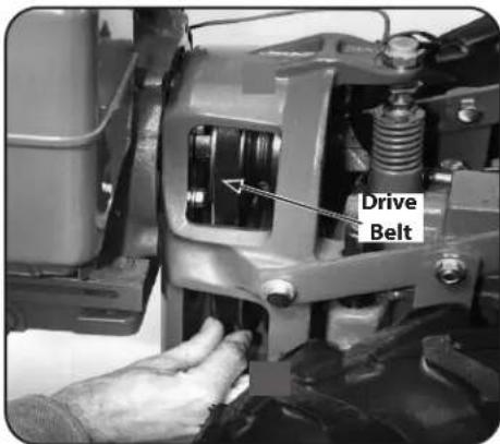
Figure 5-29
- Move the bottom half of the belt into the HIGH Range groove of the lower pulley. If extra slack is needed, hold up Wheels/Tines/PTO Drive Lever while moving the belt. Verify the belt is seated properly on the pulleys.
- To move the belt to the Low Range position. See Changing Belt Speed in the Controls & Operation section.
- After installing the belt, check and adjust for correct belt tension as explained previously.
Reverse Disc
Follow these steps to replace the reverse disc. If your tiller has a Bumper Attachment mounted, it must be removed first.
- Move Wheels/Tines/PTO Drive Lever in NEUTRAL position.
- Wedge a 5/16"-thick board between the top of the engine pulley and the cast iron housing next to it. This immobilizes the pulley. Avoid contacting the reverse disc.
- Use a 9/16" wrench to loosen the mounting bolt shown in Figure 5-30. Remember to immobilize the pulley with the wood wedge while loosening the bolt. If necessary, pry the disc from the pulley with the tip of a screwdriver. Back the bolt out as far as possible. Then angle the disc a little to remove it. Bring the bolt and lockwasher along with the disc. Installing a new reverse disc.
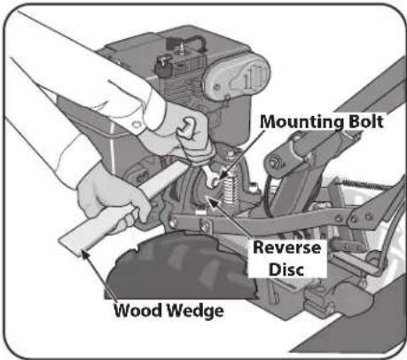
Figure 5-30
- Do Steps 1-3, in the opposite order to install the new reverse disc.
- Tighten the mounting bolt securely, and check for correct operation — see the Service section.
Tines
Inspect the tines for wear or damage after every 30 operating hours. The rate of wear depends upon the hours of use and soil conditions. With use, the tines get shorter, narrower and more pointed. See Figure 5-31.
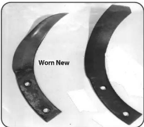
Figure 5-31
If badly worn, they lose the ability to till deeply. Worn tines leave an ever-increasing gap in the middle of a tilled row. The normal gap is 3" between the tine tips — replace the tines when the gap widens to 5". See Figure 5-32. The tines can be replaced individually or as a complete set.
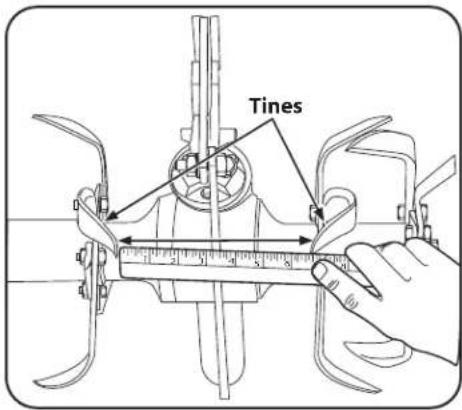
Figure 5-32
Replacing a Single Tine

WARNING! The tines or tine hooded edges may be sharp. Wear thick gloves to protect your hands from cuts or scrapes.

WARNING! Wear safety goggles to protect your eyes. When loosening hardware, do not hit a wrench with a metal tool. This could shatter the tool or wrench sending metal particles into your eyes.
- Move the Wheels/Tines/PTO Drive Lever to NEUTRAL, the Wheel Speed Lever to either FAST or SLOW position, and the Tines/PTO Clutch Lever to ENGAGE.
- Gently tilt the tiller forward until the engine rests on the ground.
- Raise the hood flap at the back of the tiller and tie it up with string.
- Before removing a tine, note in which direction the bent tip points. The new tine must be installed in the same direction.
- Use two 9/16" wrenches to remove the two bolts and nuts securing the tine to the tine holder plate. See Figure 5-33. Use penetrating oil on the hardware if it is rusted or hard to remove.
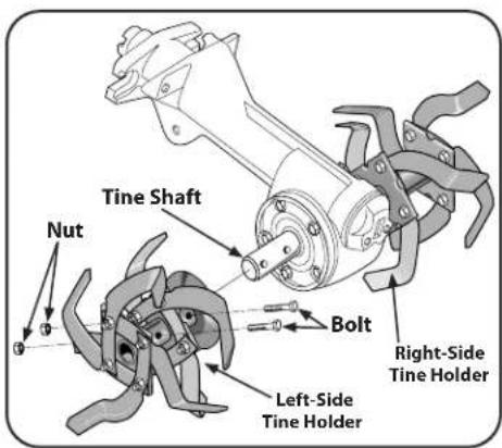
Figure 5-33
- Mount the new tine exactly the way the old tine was positioned. (The sharp edge of the tine, which enters the soil first, must face forward when above the tine shaft.) Replace the bolts and nuts and tighten them securely.
Replacing A Tine Holder Assembly
The 16 Bolo Tines are mounted eight per side on left-side and right-side tine holders. Here's how to replace the tines and holders as assemblies.
- Follow Steps 1-3 in Replacing a Single Tines above.
- Identify the tine holders as left-side and right-side holders — they must be replaced on the same side from which they were removed. Use a piece of chalk or a grease pencil to mark them L and R.
- Remove the two bolts and nuts securing each holder. See Figure 5-33.
- Use a soft mallet to drive the holder off the tine shaft. Use a heavy hammer and block of wood to knock off the immobilized tine holder.
- When the holder is off, clean all dirt and debris from the shaft and the holder. Apply fresh grease to the tine shaft.
Replacing Tines Holder Assembly
- Replace the holder so the sharp tine edges face forward (toward the front of the tiller). Tap tine holder back on the tine shaft.
- Grease the threads on the mounting bolt(s). Install and tighten the bolt(s) securely.
Troubleshooting
| ProblemCause | Remedy | |
| Wheels and tines do not turn 1. | Misadjusted drive belt and/or reverse disc | 1. See Service section |
| 2. Loose bolt on transmission drive pulley | 2. Tighten bolt | |
| 3. Worn worm gears | 3. See authorized service dealer | |
| Wheels and tines turn on top of ground, but stop or hesitate in soil | 1. Loose drive belt | 1. Adjust drive belt (See Service section) |
| 2. Loose bolt on transmission drive pulley | 2. Tighten bolt | |
| Wheels turn, but tines do not 1. | Tines/PTO Clutch Lever does not engage | 1. Engage lever |
| 2. Tines/PTO Clutch Lever out of adjustment | 2. See Service section | |
| 3. Dog clutch key missing | 3. Contact authorized service dealer | |
| 4. Worn worm gears | 4. Contact authorized service dealer | |
| 5. Missing or broken tines or tine hardware | 5. See Service section | |
| Tines turn, but wheels do not 1. | Missing Hi-Pro key inside wheel clutch | 1. Contact authorized service dealer |
| 2. Worn gears | 2. Contact authorized service dealer | |
| 3. Drive dogs on wheel clutch worn out or broken | 3. Contact authorized service dealer | |
| Wheels/Tines/PTO Drive Lever does not stay in forward | 1. Drive belt too tight | 1. See Service section |
| 2. Clutch Pawl spring overstretched | 2. Replace spring | |
| Wheels/Tines/PTO Drive Lever hard to shift into reverse | 1. Worn reverse disc | 1. Replace reverse disc |
| 2. Motor mount bars sticking | 2. Lubricate mount bars | |
| Tiller stays in reverse or forward when Wheels/Tines/PTO Drive Lever is released or lever is hard to shift | 1. Motor mount bars sticking 1. Lubricate motor mount bars | |
| Wheel Speed Lever is hard to shift | 1. Eccentric lever is sticking | 1. Lubricate the eccentric lever and linkage to wheel speed lever |
| 2. Clutch inside transmission binding | 2. Contact authorized service dealer | |
| Wheel Speed Lever shifts into FAST gear, but not SLOW | 1. Connecting rod at back of lever backwards or bent in towards transmission and hitting it | 1. Straighten or replace linkage |
| 2. Clutch inside transmission binding | 2. Contact authorized service dealer | |
| Wheel Speed Lever moves freely, but does not change gears | 1. Broken or worn eccentric shifting pin | 1. Contact authorized service dealer |
| Tiller jumps while tilling 1. Depth | Regulator Lever is too deep for soil conditions | 1. Use a shallower setting |
| Depth Regulator Lever difficult to move | 1. Depth Regulator Lever bent | 1. Straighten lever |
| 2. Depth Regulator Lever sticking | 2. Lubricate lever | |
Replacement Parts
| Component Part Number and Description | |
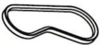 | GW-9245 V-Belt |
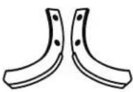 | 742-04223 Bolo Tine (LH), 12"742-04224 Bolo Tine (RH), 12" |
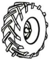 | 934-04231 Wheel, 16 x 4.6 x 8 |
 | 756-04171 Reverse Disc |
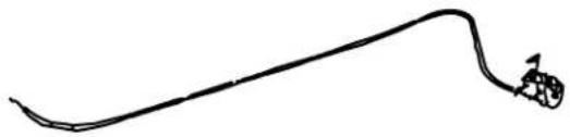 | 746-05084 Throttle Cable |
Troy-Bilt Genuine Parts can be ordered through your local authorized Troy-Bilt dealer, online at www.troybilt.com or by phone at (800) 828-5500 or (330) 558-7220. To locate your nearest authorized Troy-Bilt dealer, visit www.troybilt.com or call (800) 828-5500 or (330) 558-7220.
Notes
TROY-BILT LLC -- LIMITED WARRANTY
The limited warranty set forth herein is given by Troy-Bilt LLC with respect to a new Troy-Bilt ^16 product (hereinafter "Product") purchased and used in the United States and/or Canada to the Initial Purchaser (as defined herein). This limited warranty does not cover Emission Control Systems and is not a Federal Emission Control Warranty Statement, as defined by U.S. federal law. Please refer to the Federal Emission Control Warranty Statement in the operator's manual for warranties covering Emission Control Systems.
Scope of the Limited Warranty
Troy-Bilt LLC warrants that the Product (except with regard to the components and circumstances defined below as "Exclusions") will be free from defects in materials and workmanship during the Warranty Period, as defined below. For purposes of this limited warranty, the "Initial Purchaser" is the first person/ company to purchase this new Product from an authorized Troy-Bilt dealer, distributor, and/or retailer of such products, including a party for whom said Product was purchased as a gift. This limited warranty is non-transferrable. During the Warranty Period, Troy-Bilt LLC will, at its option, either repair or replace any original part that is covered by this limited warranty and is determined to be defective in workmanship or material. "Commercial Use" shall be defined as any commercial, professional, agricultural, institutional, or income-producing use of the Product. Product shall not be warranted for Commercial Use unless so designated in the Additional Warranty Notes.
| Troy-Bilt LLC® Warranty Information | |
| Handheld Product Warranty Period | |
| Chainsaws, Cultivators, Brushcutters, Blowers, Trimmers, Edgers, Hedgers, Pole Saws | 2 Year * |
| 51cc Backpack Blower , Troy-Bilt XP Products 3 Year * | |
| Wheeled Chore Product Warranty Period | |
| Chipper-Shredder Vacuums, Lawn Edgers, Wheeled-String Trimmers, Front Tine Tillers, Rear Tine Tillers | 2 Year |
| Gas Powered Mower Product Warranty Period | |
| Riding Mowers, Troy-Bilt – TB30, PONY, BRONCO 2 year † | |
| Riding Mowers, Troy-Bilt XP – SUPER BRONCO XP 3 year | |
| Walk-Behinds- Troy-Bilt 2 year † | |
| Walk-Behinds – Troy-Bilt XP, 28" Wide-Area Walk-Behinds 3 Year | |
| Zero-Turns - Mustang, Mustang XP 3 Year | |
| Snow Product Warranty Period | |
| Single, Two, and Three Stage 3 Year | |
| Additional Warranty Notes |
| * Handheld Products - Limited Commercial Use Warranty: Handheld products – 90 days. |
| † FOR PRODUCT SOLD IN CANADA ONLY: Riding mowers TB30, Pony, and Bronco models are covered by a three (3) year product warranty; Troy-Bilt non-XP walk-behind mowers are covered by a three (3) year product warranty. |
| Lead-Acid and AGM Batteries: Are covered by a one (1) year prorated limited warranty against defects in material and workmanship, with 100% replacement during the first three (3) months, from the date of original purchase by the Initial Purchaser. After three (3) months, the battery replacement credit is based on the months remaining in the twelve (12) month period, dating back to the date of original purchase by the Initial Purchaser. Any replacement battery will be warranted only for the remainder of the original warranty period. |
| Frames: The frame, chassis, and front axle on all Super Bronco XP's are covered for “Residential Use” by a five (5) year limited warranty. The frame on all Zero-Turn Mustang products shall be warranted against defects in material and workmanship for the lifetime of the product, namely for as long as it is owned by its Initial Purchaser or the party for whom it was originally purchased as a gift, or seven (7) years from the date of its initial sale to an Initial Purchaser, whichever comes first. |
| Mowing Decks: 1) Troy-Bilt LLC warrants the mowing decks under the warranty of the product it came with unless otherwise stated. 2) When so equipped, the optional fabricated cutting deck shell (excluding wear parts, etc. thereon) shall be warranted against defects in material and workmanship for the lifetime of the product, namely for as long as it is owned by its Initial Purchaser or the party for whom it was originally purchased as a gift, or seven (7) years from the date of its initial sale to an Initial Purchaser, whichever comes first. |
| Snow Blowers: Two Stage Arctic Storm and all Three-Stage - Auger gear boxes have a five (5) year limited warranty. When so equipped, the polymer discharge chute shall be warranted against defects in material and workmanship for the lifetime of the product, namely for as long as it is owned by its Initial Purchaser or the party for whom it was originally purchased as a gift, or seven (7) years from the date of its initial sale to an Initial Purchaser, whichever comes first. |
| Tillers: When so equipped, the bronze gear transmission shall be warranted against defects in material and workmanship for the lifetime of the product, namely for as long as it is owned by its Initial Purchaser or the party for whom it was originally purchased as a gift, or seven (7) years from the date of its initial sale to an Initial Purchaser, whichever comes first. |
| Attachments/Accessories: Please refer to warranty with Operator's Manual. |
The limited warranty is non-transferrable
How to Get Service Under This Limited Warranty
In order to qualify for the limited warranty, as set forth herein, the repairs made under this warranty must be performed by an authorized Troy-Bilt service provider. To locate a Troy-Bilt service provider, contact your authorized Troy-Bilt dealer, distributor, or retailer, or contact Troy-Bilt LLC at P.O. Box 368023, Cleveland, Ohio 44136-0019, or call 1-877-282-8684, or log on to our Website at www.troybilt.com. For Canada, contact MTD Products Limited, 97 Kent Ave, Kitchener, ON N2G 3R2, or call 1-800-668-1238, or log on to our Website at www.troybilt.ca. This limited product warranty is provided by Troy-Bilt LLC and is the only product warranty provided by Troy-Bilt LLC for the Product. A COPY OF YOUR SALES RECEIPT IS REQUIRED FOR WARRANTY SERVICE.
What This Limited Warranty Does Not Cover
This limited warranty does not cover the following (the "Exclusions"):
- Product purchased outside of the United States or Canada.
-
Emission Control Systems. These items are subject to a separate warranty under the applicable Federal Emission Control Warranty Statement. Please refer to the applicable Federal Emission Control Warranty Statement for terms and conditions relating to Emission Control Systems.
-
Damage due to lack of maintenance and/or improper maintenance, as described in the operator's manual.
-
Normal wear and tear resulting from use of the Product.
-
Normal Wear Parts (as defined herein) are warranted to be free from defects in material and workmanship for a period of thirty (30) days from the date of original purchase by the Initial Purchaser for residential use, and for 30 days or 100 hours (whichever occurs first) for Product used commercially. Depending on Product, Normal Wear Parts include, but are not limited to items such as: belts, blades, blade adapters, grass bags, rider deck wheels, seats, shave plates, skid shoes, tines, filters, nozzles, hoses, O-rings, spray guns, wands, tires, spark plugs, fuses, bump knobs, outer spools, cutting line, inner belts, starter pulley, starter rope, drive belts, saw chains, guide bars, and other consumable items.
-
Use of the product that is not consistent with the intended use thereof, as described in the operating instructions, including, but not limited to, abuse, misuse and/or neglect of the Product, or any use inconsistent with and/or non-compliant with instructions contained in the Operator's Manual. This includes operation in sandy and/or corrosive environments.
-
Any Product that has been altered or modified in a manner not consistent with the original design of the Product or in a manner not approved by Troy-Bilt LLC.
-
Paint repairs or replacements for defective paint (including materials and application) are covered for a period of three (3) months.
-
Wheel rims (when so equipped) are covered for a period of three (3) months for manufacturing defects.
This warranty does not cover, and Troy-Bilt LLC disclaims any responsibility for, matters including, but not limited to, the following:
- Loss of time or loss of use of the Product.
- Transportation costs and other expenses incurred in connection with the transport of the Product to and from the authorized Troy-Bilt service provider.
- Any loss or damage to other equipment or personal items.
- Damages caused by improper maintenance or the use of other than the specified fuel, oil, or lubricants, as approved in the operator's manual.
- Damage resulting from the installation or use of any accessory or part not approved by Troy-Bilt LLC for use with the Product.
Limitations
-
THERE ARE NO IMPLIED WARRANTIES, INCLUDING, BUT NOT LIMITED TO, ANY IMPLIED WARRANTY OF MERCHANTABILITY OR FITNESS FOR A PARTICULAR PURPOSE. NO WARRANTY SHALL APPLY AFTER THE APPLICABLE WARRANTY PERIOD, AS SET FORTH ABOVE, AS TO THE PARTS AS IDENTIFIED. NO OTHER EXPRESS WARRANTY OR GUARANTY, WHETHER WRITTEN OR ORAL, EXCEPT AS MENTIONED ABOVE, GIVEN BY ANY PERSON OR ENTITY, INCLUDING A DEALER OR RETAILER, WITH RESPECT TO ANY, PRODUCT SHALL BIND Troy-Bilt LLC. DURING THE WARRANTY PERIOD, THE EXCLUSIVE REMEDY IS REPAIR OR REPLACEMENT OF THE DEFECTIVE PART, AS SET FORTH ABOVE. (SOME STATES DO NOT ALLOW LIMITATIONS ON HOW LONG AN IMPLIED WARRANTY LASTS, SO THE ABOVE LIMITATION MAY NOT APPLY TO YOU.)
-
THE PROVISIONS, AS SET FORTH HEREIN, PROVIDE THE SOLE AND EXCLUSIVE REMEDY ARISING FROM THE SALE. Troy-Bilt LLC SHALL NOT BE LIABLE FOR INCIDENTAL OR CONSEQUENTIAL LOSS OR DAMAGES INCLUDING, WITHOUT LIMITATION, FOR TRANSPORTATION OR FOR RELATED EXPENSES, OR FOR RENTAL EXPENSES TO TEMPORARILY REPLACE A WARRANTED PRODUCT. (SOME STATES DO NOT ALLOW THE EXCLUSION OR LIMITATION OF INCIDENTAL OR CONSEQUENTIAL DAMAGES, SO THE ABOVE EXCLUSION OR LIMITATION MAY NOT APPLY TO YOU.)
-
IN NO EVENT SHALL RECOVERY OF ANY KIND BE GREATER THAN THE AMOUNT OF THE PURCHASE PRICE OF THE PRODUCT SOLD. ALTERATION OF THE SAFETY FEATURES OF THE PRODUCT SHALL VOID THIS LIMITED WARRANTY. YOU ASSUME THE RISK AND LIABILITY FOR LOSS, DAMAGE, OR INJURY TO YOU AND YOUR PROPERTY, AND/OR TO OTHERS AND THEIR PROPERTY, ARISING OUT OF THE USE OR MISUSE OR INABILITY TO USE THE PRODUCT.
-
This limited warranty extends to the Initial Purchaser only and, except as otherwise stated herein, the applicable Warranty Period will begin on the original date of purchase of the Product. In the event that the original date of purchase of the Product is indeterminable, then the Warranty Period shall be established as beginning on the Product's date of manufacture, as determined by Troy-Bilt LLC, and ending six (6) months after the applicable Product Warranty Period, as defined above. In no event shall a Product's warranty extend beyond the applicable Warranty Period.
How State Law Relates to This Warranty
This limited warranty gives you specific legal rights, and you may also have other rights, which vary from state to state.
TROY-BILT®
MANUAL DEL OPERADOR
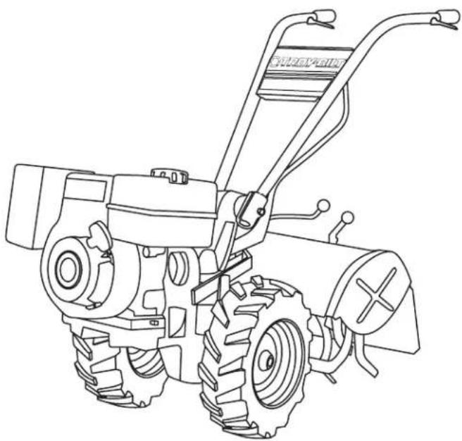
natural_image
Line drawing of a small utility tool with visible blades and handle (no text or symbols)natural_image
Row of identical empty rectangular boxes with no text or symbolsNúmero de serie

natural_image
Row of identical empty rectangular boxes with no text or symbols◇ Web: www.troybilt.com
natural_image
Close-up of a mechanical assembly with a magnified inset showing a detail (no visible text or symbols)Figura 3-3
natural_image
Close-up of a mechanical assembly with hoses and a circular component (no visible text or symbols)Figura 3-4
natural_image
Close-up of mechanical components with a circular inset showing internal components (no visible text or symbols)Figura 3-5
natural_image
Close-up of a black metal chain clamp securing a cylindrical object (no text or symbols visible)Figura 3-13
natural_image
Close-up of a person's foot using a handheld device with attached hoses and a curved cable (no text or symbols visible)Figura 4-3
natural_image
Person operating a small tiller in a grassy field with trees and rocks in the background (no visible text or symbols)Figura 4-4
natural_image
Man operating a small plow in a grassy field, no visible text or symbolsFigura 4-5
natural_image
Abstract diagram of three curved lines with arrows pointing right, no text or symbols presentFigura 4-12
natural_image
Pure diagram of a coiled pipe or coil with directional arrows, no text or symbols presentFigura 4-13
flowchart
graph TD
    A["1"] --> B["2"]
    B --> C["3"]
Figura 4-14
natural_image
Black-and-white photo of a man operating a small tiller in a field, no visible text or symbolsFigura 4-17
Compostaje enérgico
natural_image
Black-and-white photo of a person operating a small agricultural machine in a cornfield (no visible text or symbols)Figura 4-18
natural_image
Two small agricultural machines: a tracked tractor and a flat-till with a blade, shown against a plain white background (no text or symbols visible).Figura 4-19
natural_image
Close-up of a small toy vehicle with a hammer striking a block, next to a large tire (no visible text or symbols)Figura 4-20
natural_image
Close-up of a hand using a tool to adjust or install a mechanical component (no visible text or symbols)Fljgwr6398
Figura 5-13
natural_image
Line drawing of a manual tiller machine with visible blade and handle (no text or symbols)natural_image
Row of identical empty rectangular boxes with no text or symbolsNUMÉRO DE SÉRIE

natural_image
Row of identical empty rectangular boxes with no text or symbolsService après-vente
◇ Web: www.troybilt.ca
◇ Téléphone: (800) 668-1238
◇ Courrier: P. O. Box 1386, Kitchener, Ontario, Canada N2G 4J1

natural_image
Close-up of a mechanical component with a magnified inset showing a detail (no visible text or symbols)Figure 3-3
natural_image
Close-up of a mechanical assembly with hoses and a highlighted circular component (no visible text or symbols)Figure 3-4
natural_image
Close-up of a mechanical device with visible wiring and a circular component (no text or symbols)Figure 3-5
natural_image
Close-up of a black metal clamp bracket with a screw and threaded end (no text or symbols visible)Figure 3-13
natural_image
Close-up of a hand holding a flexible hose with a curved cable, no visible text or symbolsFigure 4-3
natural_image
Person operating a small utility pole in a grassy field, surrounded by trees (no visible text or symbols)Figure 4-4
natural_image
Black-and-white photo of a person operating a small plow in a grassy field (no visible text or symbols)Figure 4-5
natural_image
Abstract diagram of three curved lines with arrows indicating direction (no text or symbols)Figure 4-12
natural_image
Pure diagram of a coiled pipe or tube with directional arrows, no text or symbols presentFigure 4-13
flowchart
graph LR
    A["Stage 1"] --> B["Stage 2"]
    B --> C["Stage 3"]
Figure 4-15
natural_image
Black-and-white photo of a man operating a small tiller in a field, no visible text or symbolsFigure 4-17
Compostage
natural_image
Black-and-white photo of a person spraying crops in a dense field, no visible text or symbolsFigure 4-18
natural_image
Black-and-white photo of a small manual tiller and a larger tractor, both without any visible text or symbols.Figure 4-19
natural_image
Close-up of a small wheeled vehicle with a rubber block and tire, no visible text or symbolsFigure 4-20
natural_image
Close-up of a hand using a tool to adjust or install a mechanical component (no visible text or symbols)Figure 5-9
- Rear-Tine Tiller — Horse/Big Red
- WARNING
- To The Owner
- 1
- Thank You
- Table of Contents
- Record Product Information
- MODEL NUMBER
- SERIAL NUMBER
- Customer Support
- CALIFORNIA PROPOSITION 65
- Training
- Preparation
- Safe Handling of Gasoline:
- Operation
- Maintenance & Storage
- Notice Regarding Emissions
- Spark Arrestor
- Safety Symbols
- Assembly & Set-Up
- 3
- Contents of Carton
- Recommended Tools for Assembly
- Contents of Hardware Pack
- Assembly
- Unpacking Instructions
- Handle
- Moving the Tiller off the Shipping Platform
- Wire Harness
- Wheels/Tines PTO Drive Lever
- Engine Throttle Lever and Cable
- Electric Start System (If Equipped)
- Set-Up
- Tires
- Gas & Oil Fill-up
- Transmission Gear Oil
- Controls
- Wheels/Tines/PTO Drive Lever
- Forward Interlock Levers
- Wheel Speed Lever
- Tines/PTO Clutch Lever
- Depth Regulator Lever
- Handlebar Height Adjustment Lever
- Engine Throttle Lever
- Keyswitch Starter (If So Equipped)
- Starting the Engine
- Pre-Start Checklist
- Starting Electric Start Engine with Recoil Starter
- Cold Weather Operation
- Stopping the Engine and the Tiller
- Engaging the Drive & Tines
- Stopping Forward Motion & Tines
- Moving in Reverse
- NOTE: Do not till while in REVERSE.
- Stopping Reverse Motion
- Turning the Tiller
- Choosing Wheel & Tine Speeds
- WHEEL SPEED & BELT RANGE SELECTION GUIDE
- SLOW GEAR, LOW BELT RANGE
- SLOW GEAR, HIGH BELT RANGE
- FAST GEAR, LOW BELT RANGE
- FAST GEAR, HIGH BELT RANGE
- Changing Belt Speed
- Changing Belt From Low Range to High Range
- Changing Belt From High Range to Low Range
- Clearing the Tines
- Tilling Tips & Techniques
- Let the Tiller Do the Work
- Tilling Depths
- Avoid Tilling Wet, Soggy Soil
- Avoid Making Footprints
- Suggested Tilling Patterns
- Tilling on Slopes
- Power Composting
- Wide-Row Planting
- Tilling Under Corn
- PTO Power Feature
- Removing the Tine Attachment
- Installing the Tine Attachment
- Moving the Tiller
- Loading & Unloading the Tiller
- Loading the Tiller
- Unloading the Tiller
- Maintenance
- Engine
- Tire Pressure
- Battery
- Tine Shaft
- Wheel Shaft Maintenance
- Hardware
- Transmission Pulley Mounting Bolt
- Neutral Plunger Assembly Jam Nut
- Rear Bearing Cap Screws
- Housing Cover Bolts
- Swing Bolts
- Lock Nut on the Shifting Linkage
- Tine Hardware
- Checking for oil leaks
- Checking Gear Oil Levels
- Tine Attachment Oil Level
- For Dipsticks With Hot/Cold Markings
- Adding or Changing Gear Oil
- Adding Gear Oil to the PTO Power Unit Transmission
- Draining and Filling the PTO Power Unit Transmission
- Adding Gear Oil to the Tine Attachment Transmission
- Draining and Filling the Tine Attachment Transmission
- Forward Interlock System
- Lubrication
- Adjustments
- Drive Belt
- How to Measure the Belt Tension
- How to Adjust the Belt Tension
- Reverse Drive System
- Checking and Adjusting the Reverse Drive System
- Checking and Adjusting the Reverse Disc
- Adjusting the Reverse Drive:
- Throttle Cable
- Ignition System
- Spark Plug
- Off-Season Storage
- Belt Replacement
- Reverse Disc
- Tines
- Replacing a Single Tine
- Replacing A Tine Holder Assembly
- Replacing Tines Holder Assembly
- Troubleshooting
- Replacement Parts
- Notes
- TROY-BILT LLC -- LIMITED WARRANTY
- Scope of the Limited Warranty
- How to Get Service Under This Limited Warranty
- What This Limited Warranty Does Not Cover
- This limited warranty does not cover the following (the "Exclusions"):
- This warranty does not cover, and Troy-Bilt LLC disclaims any responsibility for, matters including, but not limited to, the following:
- Limitations
- How State Law Relates to This Warranty
- TROY-BILT®
- MANUAL DEL OPERADOR
- Número de serie
- Compostaje enérgico
- NUMÉRO DE SÉRIE
- Service après-vente
- Compostage
Brand : TROY-BILT
Model : Big Red
Category : Plane