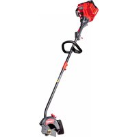
TBE252 - String Trimmer TROY-BILT - Free user manual and instructions
Find the device manual for free TBE252 TROY-BILT in PDF.


| Product type | String trimmer (lawn edger) |
| Brand | Troy-Bilt |
| Model | TBE252 |
| Engine type | 2-stroke, air-cooled |
| Displacement | 25 cc |
| Fuel tank capacity | 251 ml |
| Fuel/oil ratio | 40:1 |
| Spark plug (US) | Champion RDJ7J or equivalent |
| Spark plug (Canada) | Champion QDJ7J or equivalent |
| Electrode gap | 0.635 mm (0.025 in) |
| Maximum cutting depth | 6.3 cm (2.5 in) |
| Weight (without fuel) | 6.1 to 6.6 kg |
| Applications | Cutting and edging between lawns, driveways, sidewalks |
| Power source | Unleaded gasoline mixed with 2-stroke oil |
| Starting | Manual (starter rope) or optional electric |
| Depth adjustment | By knob on wheel |
| Air filter maintenance | Every 10 hours: clean and oil |
| Spark plug maintenance | Every 25 hours: check and replace if necessary |
| Blade replacement | Genuine part no. 791-613223 |
| Safety | Spark arrestor, on/off switch, blade guard, throttle lock |
| Required protective equipment | Safety glasses, hearing protection, gloves, shoes, long clothing |
| Safe distance for bystanders | 15 m (50 ft) minimum |
| Usage | Occasional domestic use |
Frequently Asked Questions - TBE252 TROY-BILT
2. Set the choke to position 1.
3. In a crouched position, press the throttle lock and trigger, then pull the starter rope 5 times.
4. Move the choke to position 2 and pull 5 to 10 times until it starts.
5. Let it warm up for 60 s, then move to position 3.
User questions about TBE252 TROY-BILT
0 question about this device. Answer the ones you know or ask your own.
Ask a new question about this device
Download the instructions for your String Trimmer in PDF format for free! Find your manual TBE252 - TROY-BILT and take your electronic device back in hand. On this page are published all the documents necessary for the use of your device. TBE252 by TROY-BILT.
USER MANUAL TBE252 TROY-BILT
SAVE THESE INSTRUCTIONS
IMPORTANT: Read this manual thoroughly before using this product. Follow all instructions.
English (Original Instructions)....3
WARNING: This product can expose you to chemicals including engine exhaust, which is known to the State of California to cause cancer, and carbon monoxide, which is known to the State of California to cause birth defects or other reproductive harm. For more information go to www.P65Warnings.ca.gov.

Starting and Stopping 18
Operation 22
Maintenance 25
Cleaning and Storage....31
Troubleshooting....32
All information, illustrations, and specifications in this manual are based on the latest product information available at the time of printing. We reserve the right to make changes at any time without notice.
The product may vary slightly from the illustrations contained in this manual.
NOTE: This operator's manual covers multiple models. Features may vary by model. Not all features in this manual are applicable to all models. The model depicted may differ from yours.
SAFETY
The purpose of safety symbols is to attract your attention to possible dangers. The safety symbols, and their explanations, deserve your careful attention and understanding. The safety warnings do not by themselves eliminate any danger. The instructions or warnings they give are not substitutes for proper accident prevention measures.
SYMBOL MEANING

DANGER: Signals an EXTREME hazard.
Failure to obey a safety DANGER symbol WILL result in serious injury or death to yourself or to others.

WARNING: Signals a SERIOUS hazard.
Failure to obey a safety WARNING symbol CAN result in serious injury to yourself or to others.

CAUTION: Signals a MODERATE hazard.
Failure to obey a safety CAUTION symbol MAY result in property damage or injury to yourself or to others.
NOTE: Advises you of information or instructions vital to the operation or maintenance of the equipment.
SPARK ARRESTOR NOTE
NOTE: For users on U.S. Forest Land and in the states of California, Maine, Oregon and Washington. All U.S. Forest Land and the state of California (Public Resources Codes 4442 and 4443), Oregon and Washington require, by law that certain internal combustion engines operated on forest brush and/or grass-covered areas be equipped with a spark arrestor, maintained in effective working order, or the engine be constructed, equipped and maintained for the prevention of fire. Check with your state or local authorities for regulations pertaining to these requirements. Failure to follow these requirements could subject you to liability or a fine. This unit is factory equipped with a spark arrestor. If it requires replacement, contact your local service dealer to install the appropriate muffler assembly.

WARNING: Read the operator's manual and follow all warnings and safety instructions. Failure to do so can result in serious injury to the operator and/or bystanders.
- IMPORTANT SAFETY INSTRUCTIONS
READ ALL INSTRUCTIONS BEFORE OPERATING

WARNING: When using the unit, all safety instructions must be followed. Please read these instructions before operating the unit in order to ensure the safety of the operator and any bystanders. Please keep these instructions for later use.
- Read the instructions carefully. Be familiar with the controls and proper use of the unit. Know how to stop the unit and disengage the controls quickly.
- Stay alert. Do not operate this unit when tired, ill or under the influence of alcohol, drugs or medication.
- Never allow children to operate the unit. Teens must be trained, accompanied and supervised by an adult. Never allow adults to operate the unit without proper instruction.
- All guards and safety attachments must be installed properly before operating the unit.
- Inspect the unit before use. Check for damaged parts. Check for fuel leaks. Make sure all parts operate properly. Make sure all fasteners are in place and secure. Make sure all moving parts are properly aligned and are not bound. Replace parts that are cracked, chipped, or damaged in any way. Have all damaged or improperly working parts repaired or replaced by an authorized service center. Do not operate the unit with loose or damaged parts.
- Be aware of risk of injury to the head, hands and feet.
- Carefully inspect the area before starting the unit. Remove rocks, broken glass, nails, wire, string and other objects that may be thrown or become entangled with the unit.
- Clear the area of children, bystanders and pets; keep them outside a 50-foot (15 m) radius, at a minimum. Even then, they are still at risk from thrown objects. Encourage bystanders to wear eye protection. If you are approached, stop the unit immediately.
- Squeeze the throttle control and check that it returns automatically to the idle position. Make all adjustments or repairs before using the unit.
- Do not change the engine governor settings or overspeed the engine.
- This unit is intended for occasional, household use only.

WARNING: Gasoline is highly flammable and its vapors can explode if ignited. Take the following precautions:
- Store fuel only in containers specifically designed and approved for the storage of such materials.
• Always stop the engine and allow it to cool before filling the tank. Never remove the fuel tank cap or add fuel when the engine is hot. Always loosen the fuel tank cap slowly to relieve any pressure in the tank before fueling. - Always mix and add fuel in a clean, well-ventilated outdoor area where there are no sparks or flames. DO NOT smoke.
- Never operate the unit without the fuel cap securely in place.
- Avoid creating a source of ignition for spilled fuel. Wipe up any spilled fuel from the unit immediately, before starting the unit. Move the unit at least 30 ft. (9.1 m) from the fueling source and site before starting the engine. DO NOT smoke.
- Never start or run the unit inside a closed room or building. Breathing exhaust fumes can kill. Operate this unit only in a well-ventilated outdoor area.
WHILE OPERATING
- Wear safety glasses or goggles that meet current ANSI / ISEA Z87.1 standards and are marked as such. Wear ear/hearing protection when operating this unit. Wear a face mask or dust mask if the operation is dusty.
- Wear heavy long pants, boots, gloves and a long sleeve shirt. Do not wear loose clothing, jewelry, short pants, sandals or go barefoot. Secure hair above shoulder level.
- Adjust the handle to provide the best grip, if applicable.
- Use the unit only in daylight or good artificial light.
- Avoid accidental starting. Be in the starting position whenever pulling the starter rope. The operator and unit must be in a stable position while starting. Refer to Starting and Stopping.
- Use the right tool. Only use this tool for its intended purpose. Only use the unit as described in this manual.
- Always hold the unit with both hands when operating. Keep a firm grip on both handles or grips.
- Do not overreach. Always keep proper footing and balance. Take extra care when working on stairs, steep slopes or inclines. To avoid serious injury, do not operate the unit while on a ladder or a roof.
- Keep hands, face, and feet away from all moving parts. Do not touch or try to stop moving parts.
- Do not touch the engine, gear housing or muffler. These parts get extremely hot from operation, even after the unit is turned off.
-
To prevent serious personal injury, avoid arm contact with the engine while operating the unit. The engine may be extremely hot.
-
Do not operate the unit faster than the speed needed to do the job. Do not run the unit at high speed when not in use.
- Do not force the unit. It will do a better, safer job when used at the intended rate.
- Always turn the unit off when operation is delayed or when carrying the unit from one location to another. Make sure all moving parts come to a complete stop.
- Before setting the unit down, always make sure the engine is off and all moving parts have stopped.
- If the unit strikes or becomes entangled with a foreign object, stop the unit immediately. Check for damage. If damaged, do not restart or operate the unit until it is repaired. Do not operate the unit with loose or damaged parts.
- Turn the engine off and disconnect the spark plug for maintenance or repair.
- Use only original equipment manufacturer (OEM) replacement parts and accessories for this unit. These are available from your authorized service dealer. Use of any other parts or accessories could lead to serious injury to the user, or damage to the unit, and void the warranty.
- Keep the unit clean. Carefully remove vegetation and other debris that could block moving parts.
- To reduce fire hazard, replace a faulty muffler and spark arrestor. Keep the engine and muffler free from grass, leaves, excessive grease or carbon build up.
- If the unit starts to vibrate abnormally, stop the unit immediately. Inspect the unit for the cause of the vibration. Vibration is generally an indicator of trouble.
EDGER SAFETY

DANGER: Keep all body parts (hands, feet, face, etc.) away from moving blades. Contact with moving blades will result in serious personal injury.
- Make sure the blade is properly installed and securely fastened before operating the unit.
- Make sure the blade shield is securely fastened before operating the unit.
- Make sure the blade is not in contact with anything before starting the unit.
- The blade should remain stationary when the engine idles. If it does not, refer to Adjusting the Idle Speed.
• Always hold the unit with both hands when operating. Using only one hand could lead to a loss of control and result in serious personal injury. - Use extreme caution when reversing or pulling the unit towards you.
- Blade thrust may occur when the spinning blade contacts an object that it does not immediately cut. Blade thrust can be violent enough to propel the unit and/or operator in any direction, possibly causing a loss of control. Blade thrust can occur without warning if the blade snags, stalls or binds. This is more likely to occur in areas where it is difficult to see the material being cut.
-
The blade will continue to spin after the unit is turned off. A coasting blade can cause serious injury. Maintain control of the unit until all moving parts have stopped.
-
Do not operate the unit with a bent, cracked or dull blade. Replace bent, cracked or dull blades.
- The blade may become very sharp from use. Always wear heavy gloves when handling, replacing or cleaning the blade.
OTHER SAFETY WARNINGS
- Maintain the unit with care. Follow all maintenance instructions in this manual.
- Do not perform maintenance procedures other than those described in this manual. All service, other than the maintenance procedures described in this manual, should be performed by an authorized service dealer.
- Never remove, modify or make inoperative any safety device furnished with the unit.
-
Before inspecting, maintaining, cleaning, storing, transporting or replacing any parts on the unit:
-
Stop the unit. Refer to Starting and Stopping.
- Make sure all moving parts have stopped.
- Allow the unit to cool.
-
Disconnect the spark plug wire.
-
Secure the unit while transporting.
- Never store the unit with fuel in the tank, inside a building where fumes may reach an open flame (pilot lights, etc.) or sparks (switches, electrical motors, etc.).
- Store the unit in a dry place, secured or at a height to prevent unauthorized use or damage. Keep the unit out of the reach of children.
- Never douse or squirt the unit with water or any other liquid. Keep handles dry and clean (free from debris, oil and grease). Clean the unit after each use. Refer to Cleaning and Storage. Do not use solvents or strong detergents.
- Keep these instructions. Refer to them often and use them to instruct other users. If you loan this unit to others, also loan them these instructions.
SAVE THESE INSTRUCTIONS
SAFETY & INTERNATIONAL SYMBOLS
This operator's manual describes safety and international symbols and pictographs that may appear on this product. Read the operator's manual for complete safety, assembly, operating and maintenance and repair information.
SYMBOL MEANING
 | SAFETY ALERT SYMBOLIndicates danger, warning or caution. May be used in conjunction with other symbols or pictographs. |
 | READ OPERATOR'S MANUALWARNING: Read the operator's manual(s) and follow all warnings and safety instructions. Failure to do so can result in serious injury to the operator and/or bystanders. |
 | WEAR EYE AND HEARING PROTECTIONWARNING: Thrown objects and loud noise can cause severe eye injury and hearing loss. Wear eye protection meeting current ANSI / ISEA Z87.1 standards and ear protection when operating this unit. Use a full face shield when needed. |
 | WEAR FOOT PROTECTIONAlways wear heavy-duty, non-slip footwear when operating this unit. |
 | WEAR HAND PROTECTIONAlways wear heavy-duty, non-slip gloves when handling this unit. |
 | HANDLE POSITIONMake sure the handle is positioned beyond the end of the safety label. |
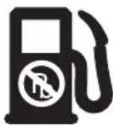
 | UNLEADED FUELAlways use clean, fresh unleaded fuel. |
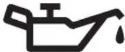
 | OILRefer to operator's manual for the proper type of oil. |
 | DO NOT USE E85 FUEL IN THIS UNITCAUTION: It has been proven that fuel containing greater than 10% ethanol will likely damage this engine and void the warranty. |
SYMBOL MEANING
| ON / OFF STOP CONTROLON / START / RUN | |
 | ON / OFF STOP CONTROLOFF or STOP |
 | PRIMER BULBSlowly press and release the primer bulb 10 times. If fuel cannot be seen in the primer bulb, press and release the primer bulb until fuel is visible. |
| CHOKE CONTROL1. FULL choke position2. PARTIAL choke position3. RUN choke position | |
 | THROWN OBJECTS CAN CAUSE SEVERE INJURYWARNING: Small objects can be propelled at high speed, causing injury. |
Min. 50 ft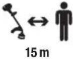 | KEEP BYSTANDERS AWAYWARNING: Keep all bystanders, especially children and pets, at least 50 feet (15 m) from the operating area. |
 | HOT SURFACEWARNING: Do not touch a hot muffler or cylinder. You may get burned. These parts get extremely hot from operation. When turned off, they remain hot for a short time. |
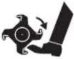 | ROTATING BLADE CAN CAUSE SEVERE INJURYWARNING: Stop the unit and allow the blade to stop before replacing the blade, cleaning or performing any maintenance. Keep hands and feet away from moving parts. |
NOTE: The model depicted may differ from yours.
APPLICATIONS (AS AN EDGER)\*
- Trim and define edges between lawns and walkways, driveways, etc.
- Only use lawn edgers to cut grass and turf
*Other optional attachments may be used with this unit.
ASSEMBLY TOOLS REQUIRED
- Flat-head screwdriver
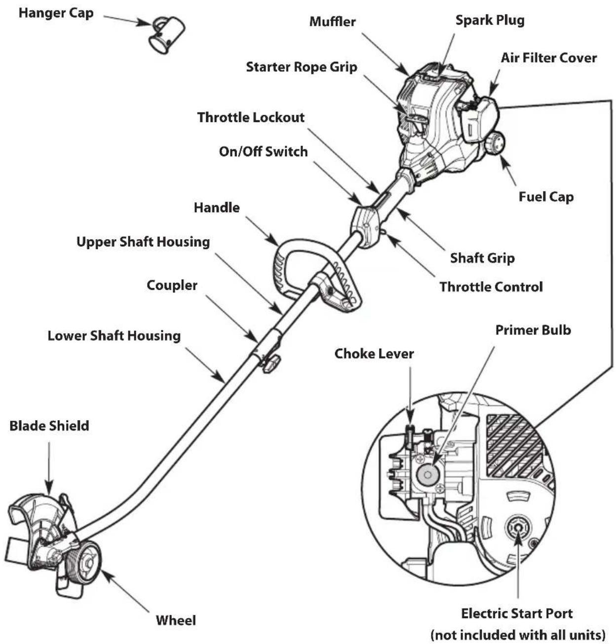
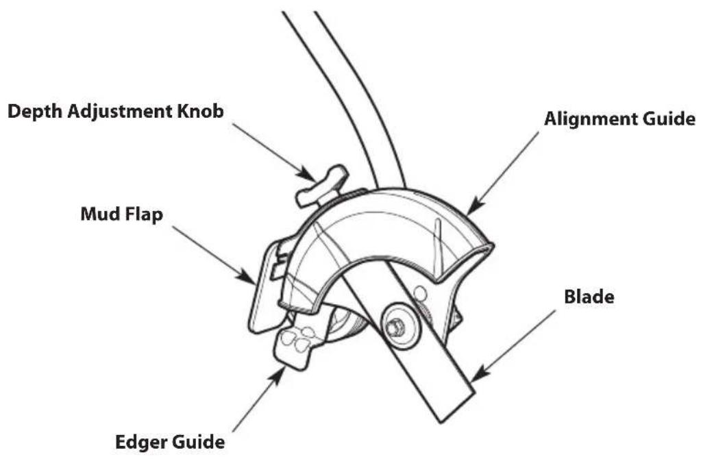
SPECIFICATIONS\*
Engine Type ....... Air-Cooled, 2-Cycle
Displacement.... 25 cc (1.52 cu. in.)
Spark Plug Gap 0.025 in. (0.635 mm)
Spark Plug (USA) ....Champion® RDJ7J or Equivalent Plug
Spark Plug (Canada).....Champion® QDJ7J or Equivalent Plug
Lubrication Fuel/Oil Mixture
Fuel/Oil Ratio 40:1
Fuel Tank Capacity 8.5 fl. oz. (251 ml)
Approximate Unit Weight (No Fuel) (Varies by Model).... 13.5 - 14.5 lbs. (6.1 - 6.6 kg)
Cutting Depth (maximum) 2.5 in. (6.3 cm)
Canada: This spark ignition system complies with Canadian ICES-002.
* All specifications are based on the latest product information available at the time of printing. We reserve the right to make changes at any time without notice.
ASSEMBLY
INSTALLING AND REMOVING THE ATTACHMENT
The coupler enables the use of various optional attachments.

WARNING: Before using any attachment, read and understand the manual that came with the attachment. Follow all safety information contained within.

WARNING: To avoid serious personal injury and damage to the unit, shut the unit off before removing or installing an attachment.
Installing the Attachment
- Remove the hanger cap from the attachment. Keep the hanger cap for use when storing the attachment. If present, remove the gray spacer from the coupler.
- Set the unit on a flat, level surface.
- Turn the knob counterclockwise to loosen the coupler (Fig. 1).
- Align the release button with the guide recess (Fig. 3).
- Push the attachment straight into the coupler (Fig. 2) until the release button snaps firmly into the primary hole (Fig. 3).
- Turn the knob clockwise to tighten the coupler (Fig. 1).

WARNING: Before operating the unit, make sure the release button is fully snapped into the primary hole and the knob is securely tightened.

WARNING: Unless specified otherwise, the release button should be snapped into the primary hole only. Using the wrong hole could lead to personal injury or damage to the unit.
Removing the Attachment
- Set the unit on a flat, level surface.
- Turn the knob counterclockwise to loosen the coupler (Fig. 1).
- Press and hold the release button (Fig. 3).
- Pull the attachment straight out of the coupler (Fig. 2).
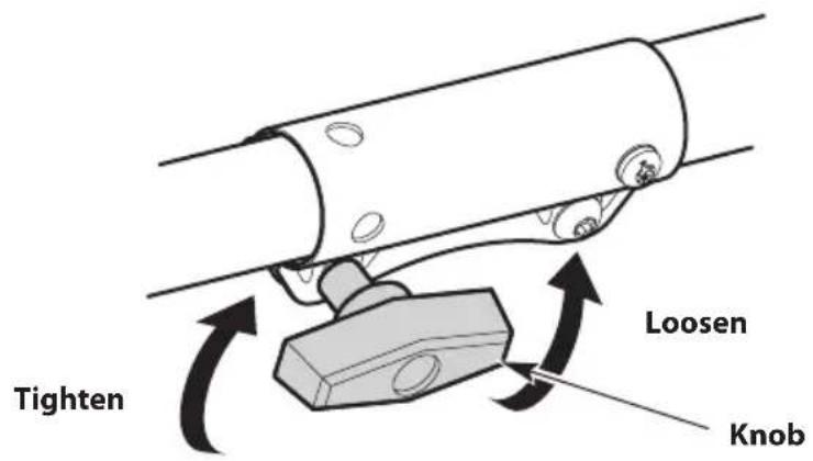
Fig. 1
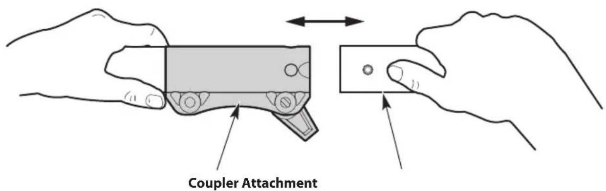
Fig. 2
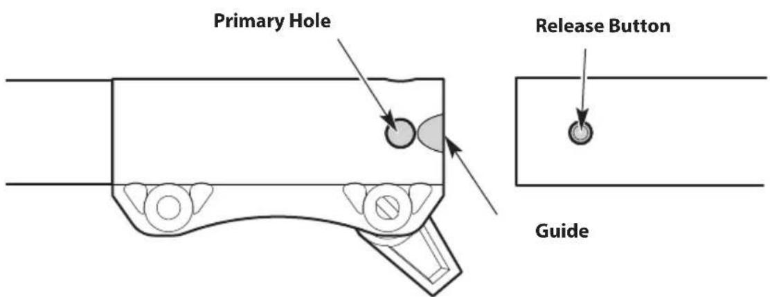
Fig. 3
INSTALLING AND ADJUSTING THE HANDLE
(Handle Type A or B)
Installing the Handle
- Push the handle down onto the upper shaft housing (Fig. 4 or Fig. 5). Make sure the bolt hole faces to the right (Fig. 4 or Fig. 5).
- Insert the bolt into the bolt hole and push it through (Fig. 4 or Fig. 5). Tighten the bolt with a flat-head screwdriver, but do not tighten the bolt completely.
- Hold the unit in the operating position (Fig. 10). Move the handle up or down the upper shaft housing to a comfortable location (Fig. 4 or Fig. 5). Make sure the handle is positioned beyond the end of the safety label (Fig. 4 or Fig. 5).
- Tighten the bolt with a flat-head screwdriver until the handle is secure.
Adjusting the Handle
If the handle requires adjustment:
- Loosen the bolt with a flat-head screwdriver (Fig. 4 or Fig. 5).
-
Hold the unit in the operating position (Fig. 10). Move the handle up or down the upper shaft housing to a comfortable location (Fig. 4 or Fig. 5). Make sure the handle is positioned beyond the end of the safety label (Fig. 4 or Fig. 5).
-
Tighten the bolt with a flat-head screwdriver until the handle is secure.
A
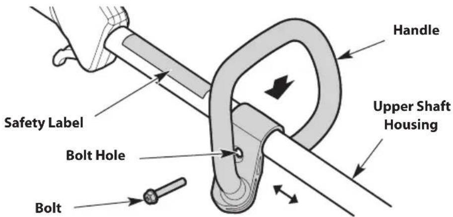
Fig. 4
B
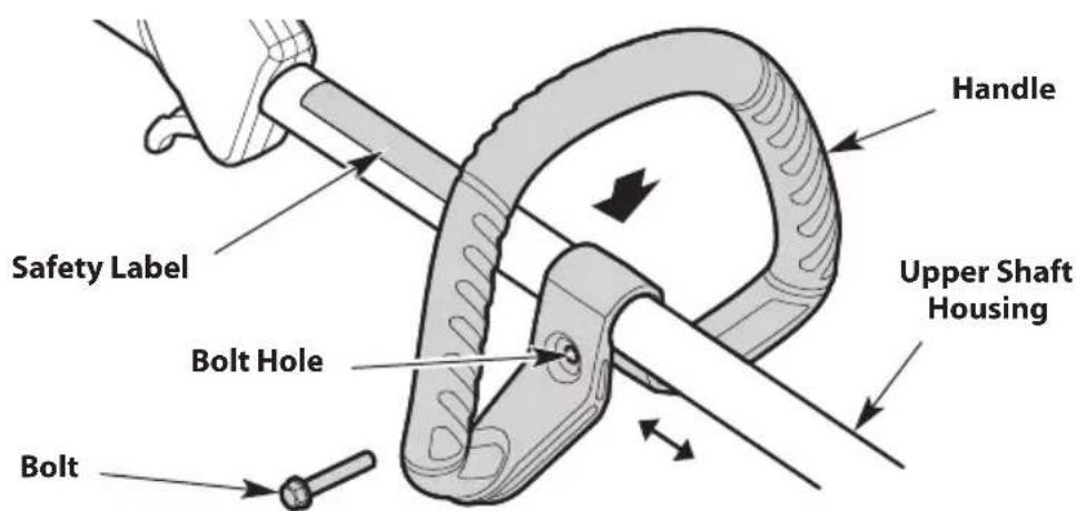
Fig. 5
OIL AND FUEL
OIL AND FUEL MIXING INSTRUCTIONS
The use of old and/or improperly mixed fuel is the most common cause of performance problems. Use only fresh, clean unleaded gasoline. Follow the instructions carefully for the proper gasoline/oil mixture.
Definition of Blended Fuels
Today's fuels are often a blend of gasoline and oxygenates such as ethanol, methanol or MTBE (ether). Alcohol-blended fuel absorbs water. As little as 1% water in the fuel can make fuel and oil separate, forming acids when stored. ALWAYS use fresh fuel (less than 30 days old).
NOTE: Dispose of old fuel according to federal, state and local regulations.
Using Blended Fuels
If using a blended fuel:
• Always use the fresh fuel mix explained in this operator's manual
- Use a fuel additive
• Always agitate the fuel mix before fueling the unit

CAUTION: DO NOT USE E85 FUEL IN THIS UNIT.
It has been proven that fuel containing greater than 10% ethanol will likely damage this engine and void the warranty.
Using Fuel Additives
The container of 2-cycle oil provided with this unit includes a fuel additive to help inhibit corrosion and minimize gum deposits. Always use the brand of 2-cycle oil that came with this unit. If this is unavailable, use a 2-cycle oil designed for air-cooled engines and mix it with a fuel additive. Add 0.8 oz. (23 ml) of fuel additive per gallon of fuel, according to the instructions on the container. NEVER add fuel additives directly to the unit's fuel tank.
Mixing the Fuel
NOTE: This unit comes with a 3.2 oz. (95 ml) container of 2-cycle oil. To obtain the correct fuel mixture described below, pour the entire container into one gallon of unleaded gasoline.

CAUTION: For proper engine operation and maximum reliability, pay strict attention to the gasoline and oil mixing instructions on the 2-cycle oil container. Using improperly mixed fuel can severely damage the engine.
Thoroughly mix the proper ratio of unleaded gasoline with 2-cycle engine oil. Do not mix them directly in the unit's fuel tank. Use a separate fuel can. Use a 40:1 gasoline/oil ratio. See the table below for specific gasoline and oil mixing ratios.
 |  |
| Unleaded gasoline 2-cycle oil | |
| 1 gallon U.S.(3.8 liters) | 3.2 fl. oz.(95 ml) |
| 1 liter 25 ml | |
MIXING RATIO - 40:1
FUELING THE UNIT

WARNING: Gasoline is extremely flammable. Ignited vapors may explode. Always stop the engine and allow it to cool before filling the fuel tank. Do not smoke while filling the tank. Keep sparks and open flames at a distance from the area.

WARNING: Remove the fuel cap slowly to avoid injury from fuel spray. Never operate the unit without the fuel cap securely in place.

WARNING: Add fuel in a clean, well-ventilated outdoor area. Wipe up any spilled fuel immediately. Avoid creating a source of ignition for spilled fuel. Do not start the engine until fuel vapors dissipate.
- Position the unit with the fuel cap facing up.
- Slowly remove the fuel cap.
- Place the fuel container spout into the fuel tank fill hole and fill the tank.
NOTE: DO NOT overfill the tank.
-
Wipe up any fuel that may have spilled.
-
Reinstall the fuel cap.
-
Move the unit at least 30 ft. (9.1 m) from the fuel container and the fueling site before starting the engine.
STARTING AND STOPPING

WARNING: Operate this unit only in a well-ventilated outdoor area. Carbon monoxide exhaust fumes can be lethal in a confined area.

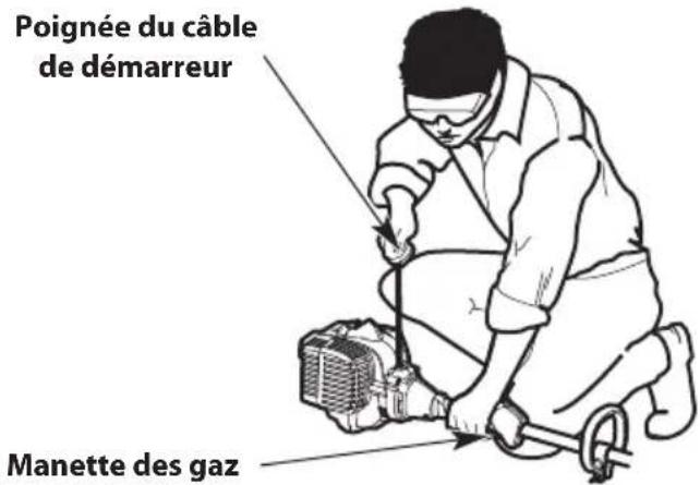
WARNING: Avoid accidentally starting the unit. To avoid serious injury, the operator and the unit must be in a stable position when pulling the starter rope (Fig. 8).
STARTING INSTRUCTIONS
NOTE: To prevent the throttle control from being squeezed accidentally, this unit has a throttle lockout. The throttle control cannot be squeezed unless the throttle lockout is also engaged.
NOTE: There is no need to turn the unit on. The On/Off switch is in the On (1) position at all times (Fig. 6).
Before Starting the Unit
- Mix gasoline with oil. Refer to Oil and Fuel Mixing Instructions.
- Fill the fuel tank. Refer to Fueling the Unit.
Starting the Unit
PRIME:
- Slowly press and release the primer bulb 10 times (Fig. 7). If fuel cannot be seen in the primer bulb, press and release the primer bulb until fuel is visible.
- Move the choke lever to Position 1 (Fig. 7).
- Crouch in the starting position (Fig. 8).
- Press and hold the throttle lockout (Fig. 6). Squeeze and hold the throttle control (Fig. 6).
NOTE: Continue to SQUEEZE and HOLD the throttle lockout and the throttle control for ALL further steps.
- Pull the starter rope with a controlled and steady motion 5 times (Fig. 8). DO NOT pull the starter rope more than 5 times.
START:
- Move the choke lever to Position 2 (Fig. 7).
- Pull the starter rope with a controlled and steady motion 5 to 10 times to start the engine.
- Allow the engine to warm up for 60 seconds.
- Move the choke lever to Position 3 (Fig. 7). Allow the engine to warm up for an additional 60 seconds. The unit may be used during this time.
NOTE: The engine is properly warmed up when it accelerates without hesitation.
IF... the engine hesitates, return the choke lever to Position 2 and continue the warm-up.
IF... the engine does not start, repeat the starting procedure.
IF... the engine fails to start after a few attempts: Move the choke lever to Position 3. Press and hold the throttle lockout. Squeeze and hold the throttle control. Pull the starter rope with a controlled and steady motion until the unit starts.
IF... the engine is already warm: Move the choke lever to Position 3. Press and hold the throttle lockout. Squeeze and hold the throttle control. Pull the starter rope with a controlled and steady motion until the unit starts.
STOPPING INSTRUCTIONS
-
Release the throttle control and allow the engine to idle.
-
Press and hold the On/Off switch in the Off (O) position until the engine comes to a complete stop (Fig. 6).
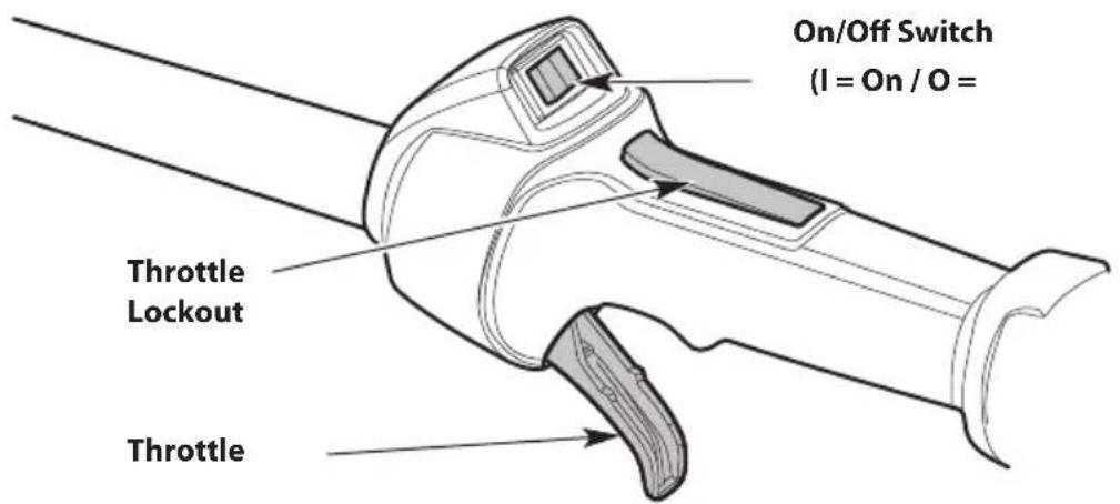
Fig. 6
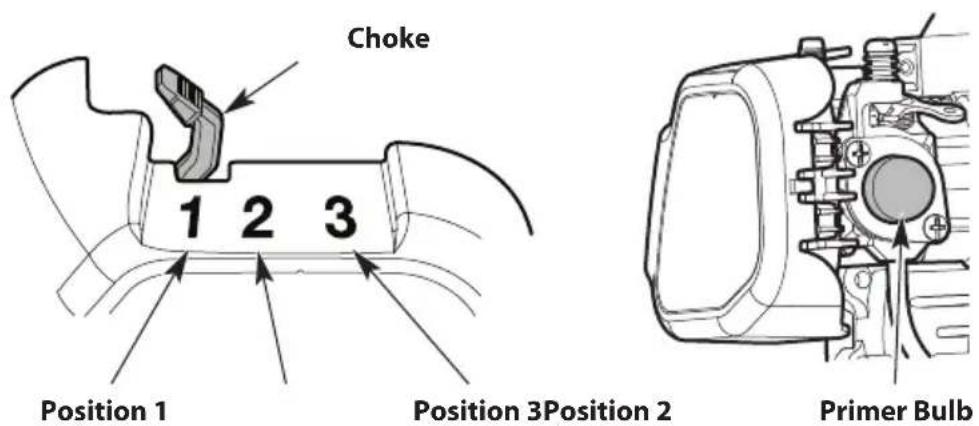
Fig. 7
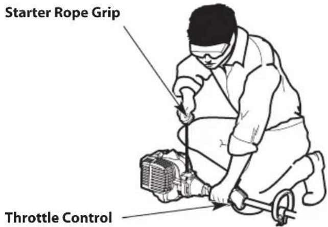
Starting Position
Fig. 8
USING THE ELECTRIC START ACCESSORY
Some units can be started with an optional electric start accessory (items sold separately). Electric-start-capable units are labeled as such and include an electric start port (Fig. 9).
Please contact your local retailer, call the Customer Support Department or visit our website for more information.
Read the Operator's Manual that came with the electric start accessory before attempting these instructions.
STARTING INSTRUCTIONS
NOTE: To prevent the throttle control from being squeezed accidentally, this unit has a throttle lockout. The throttle control cannot be squeezed unless the throttle lockout is also engaged.
NOTE: There is no need to turn the unit on. The On/Off switch is in the On (1) position at all times (Fig. 6).
Before Starting the Unit
- Mix gasoline with oil. Refer to Oil and Fuel Mixing Instructions.
- Fill the fuel tank. Refer to Fueling the Unit.
Starting the Unit
PRIME:
- Slowly press and release the primer bulb 10 times (Fig. 7). If fuel cannot be seen in the primer bulb, press and release the primer bulb until fuel is visible.
- Move the choke lever to Position 1 (Fig. 7).
- Crouch in the starting position (Fig. 8).
- Insert the electric start accessory into the electric start port (Fig. 9).
- Press and hold the throttle lockout (Fig. 6). Squeeze and hold the throttle control (Fig. 6).
NOTE: Continue to SQUEEZE and HOLD the throttle lockout and the throttle control for ALL further steps.
- Run the electric start accessory for 2 seconds. DO NOT run the electric start accessory for more than 2 seconds.
START:
- Move the choke lever to Position 2 (Fig. 7).
- Run the electric start accessory in intervals no longer than 2 seconds each until the unit starts.
- Remove the electric start accessory from the unit, unless specified otherwise in the electric start accessory Operator's Manual.
- Allow the engine to warm up for 60 seconds.
- Move the choke lever to Position 3 (Fig. 7). Allow the engine to warm up for an additional 60 seconds. The unit may be used during this time.
NOTE: The engine is properly warmed up when it accelerates without hesitation.
IF... the engine hesitates, return the choke lever to Position 2 and continue the warm-up.
IF... the engine does not start, repeat the starting procedure.
IF... the engine fails to start after a few attempts: Move the choke lever to Position 3. Insert the electric start accessory into the electric start port. Press and hold the throttle lockout. Squeeze and hold the throttle control. Run the electric start accessory in intervals no longer than 2 seconds each until the unit starts. Remove the electric start accessory from the unit, unless specified otherwise in the electric start accessory Operator's Manual.
IF... the engine is already warm: Move the choke lever to Position 3. Insert the electric start accessory into the electric start port. Press and hold the throttle lockout. Squeeze and hold the throttle control. Run the electric start accessory in intervals no longer than 2 seconds each until the unit starts. Remove the electric start accessory from the unit, unless specified otherwise in the electric start accessory Operator's Manual.
STOPPING INSTRUCTIONS
- Release the throttle control and allow the engine to idle.
- Press and hold the On/Off switch in the Off (O) position until the engine comes to a complete stop (Fig. 6).
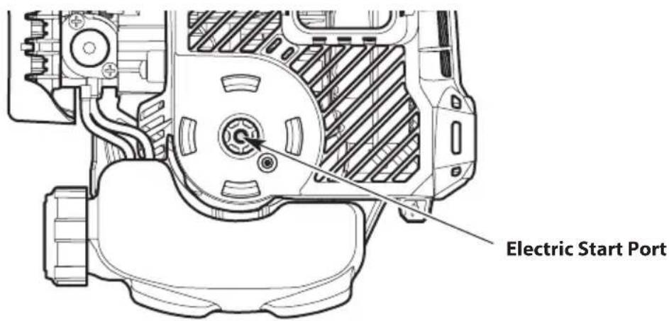
Fig. 9
OPERATION
HOLDING THE UNIT

DANGER: Keep all body parts (hands, feet, face, etc.) away from moving blades. Contact with moving blades will result in serious personal injury.

WARNING: Always wear eye, hearing, hand, foot and body protection to reduce the risk of injury when operating this unit. Wear a face mask or dust mask if the operation is dusty.

WARNING: To prevent serious personal injury, avoid arm contact with the engine while operating the unit. The engine may be extremely hot.
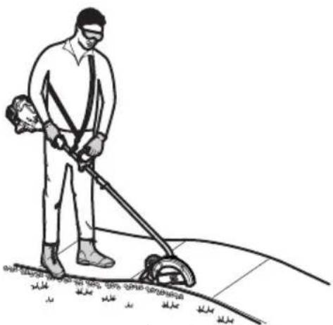
- Stand in the operating position (Fig. 10). Stand up straight. Do not bend over.
- Keep feet apart and firmly planted.
- Hold the unit with a firm grip.
- Hold the shaft grip with the right hand. Keep the right arm slightly bent.
- Hold the handle with the left hand. Keep the left arm straight.
- Hold the unit at waist level.
- Hold the unit so that it easily contacts the ground without the need for bending over.
natural_image
Line drawing of a person using a lawn power shaver to clean or work on a tiled floor (no text or symbols)Fig. 10
TIPS FOR BEST RESULTS
- Keep the wheel on the sidewalk or pavement.
- To protect the sidewalk or pavement from damage, keep the edger guide in contact with the edge of the sidewalk or pavement.
- Use the alignment guide to help maintain proper alignment (Fig. 11).
- Keep the blade perpendicular to the ground.
- DO NOT force the unit. Make the first cut no more than 1/2" deep. Increase the depth by 1/2" and cut the area again. Repeat this process until the desired depth is achieved. Refer to Adjusting the Cutting Depth.
- Cut at a slow, even pace.

WARNING: Blade thrust can occur when the spinning blade contacts an object that it does not immediately cut. Blade thrust can be violent enough to cause the unit and/or operator to be propelled in any direction and possibly lose control of the unit. Blade thrust can occur without warning if the blade snags, stalls or binds. This is more likely to occur in areas where it is difficult to see the material being cut.
- Frequently check the condition of the blade. As it wears, the blade will become smaller, reducing the cutting depth. Replace the blade as needed. Refer to Replacing the Blade.

WARNING: The blade will continue to spin for a while after the unit is turned off. To avoid serious personal injury, do not touch a coasting blade.

WARNING: To avoid serious personal injury, always turn the unit off before removing debris from the unit. Allow the blade to come to a complete stop.
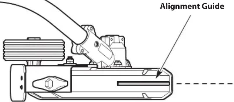
Fig. 11
ADJUSTING THE CUTTING DEPTH

WARNING: To avoid serious personal injury, always stop the unit and allow it to cool before adjusting the cutting depth. Disconnect the spark plug wire to prevent the unit from starting accidentally.
- Loosen the depth adjustment knob (Fig. 12).
- Slide the wheel up or down to the desired height.
NOTE: Lowering the wheel will decrease the cutting depth. Raising the wheel will increase the cutting depth.
- Tighten the depth adjustment knob.
- Reconnect the spark plug wire and continue use.
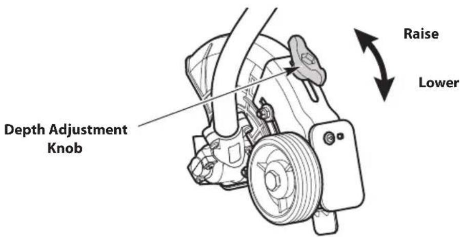
Fig. 12
MAINTENANCE

WARNING: To avoid serious personal injury, always stop the engine and allow it to cool before cleaning or maintaining the unit. Never perform cleaning or maintenance while the unit is running. Disconnect the spark plug wire to prevent the unit from starting accidentally.

WARNING: Wear protective clothing and observe all safety instructions to prevent serious personal injury.
MAINTENANCE SCHEDULE
Perform these required maintenance procedures at the frequency stated in the table. These procedures should also be a part of any seasonal tune-up.
NOTE: Some maintenance procedures may require special tools or skills. If you are unsure about these procedures, take the unit to an authorized service dealer. Refer to the Service / Warranty Supplement for more information.
NOTE: Maintenance, replacement, or repair of the emission control devices and system may be performed by an authorized service dealer. Refer to the Service / Warranty Supplement for more information.
NOTE: Please read the California/EPA statement that came with the unit for a complete listing of terms and coverage for the emissions control devices, such as the spark arrestor, muffler, carburetor, etc.
| FREQUENCY MAINTENANCE REQUIRED | |
| Every 10 hours • Clean and re-oil the air filter. Refer to Maintaining the Air Filter. | |
| Every 25 hours • Check the spark plug condition and gap. Refer to Maintaining the Spark Plug. |
REPLACING THE BLADE

WARNING: To avoid serious personal injury, always wear gloves when handling the blade.
NOTE: When replacing the blade, always use replacement part #791-613223.
Removing the Blade
- Align the output shaft hole with the locking rod slot. Insert the locking rod through the locking rod slot and into the output shaft hole (Fig. 13).
- Keep the locking rod in place by holding it next to the lower shaft housing (Fig. 14).
- While holding the locking rod, loosen the lock nut by turning it clockwise with a wrench (Fig. 15).
- Remove the locking rod. Remove the lock nut, blade retainer and blade (Fig. 16). Keep the lock nut and blade retainer for installing the new blade.
Installing the Blade
-
Lower the new blade onto the output shaft bushing (Fig. 16). Make sure the blade is flat against the output shaft bushing.
-
Place the blade retainer onto the output shaft with the flat surface against the blade (Fig. 16).
-
Screw the nut onto the output shaft (Fig. 16).
-
Align the output shaft hole with the locking rod slot. Insert the locking rod through the locking rod slot and into the output shaft hole (Fig. 13).
-
Keep the locking rod in place by holding it next to the shaft housing (Fig. 14).
-
While holding the locking rod, tighten the lock nut by turning it counterclockwise (Fig. 15). Make sure that the blade stays flat and centered against the output shaft while tightening the lock nut. If you have a torque wrench, tighten the lock nut to 325-335 in·lbs (37-38 N·m).
If you do not have a torque wrench, tighten the lock nut with a wrench, until the lock nut presses against the blade retainer and the blade is snug. Make sure the blade is installed correctly, then rotate the nut an additional 1/4-1/2 turn.

WARNING: Make sure the blade is flat against the output shaft bushing after the lock nut is tightened. If the blade is off-center, the unit will be damaged by vibration, and the blade may fly off, which can cause serious personal in ju ry.
- Remove the locking rod.

WARNING: To avoid serious personal injury or damage to the unit, do not start or operate the unit with the locking rod inserted into the locking rod slot.
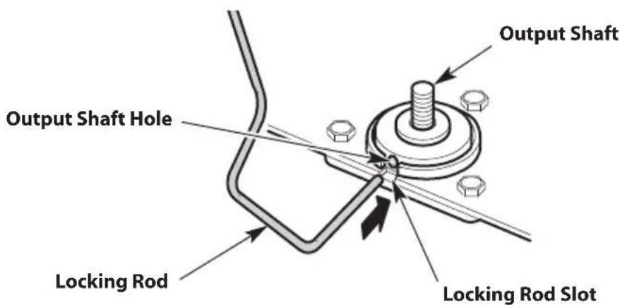
Fig. 13
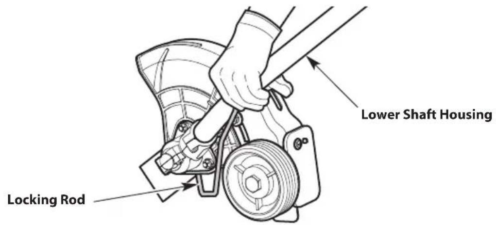
Fig. 14
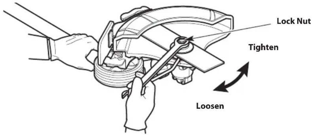
Fig. 15
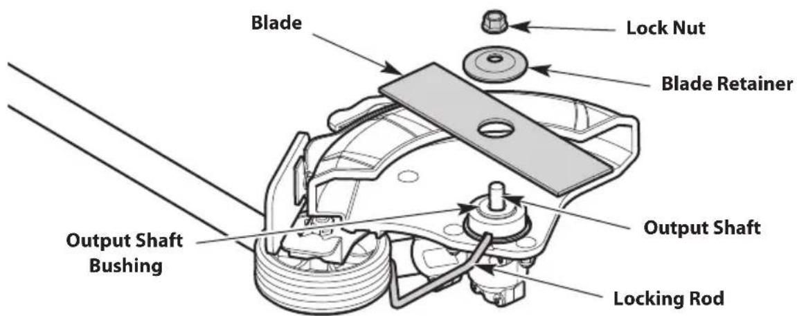
Fig. 16
MAINTAINING THE AIR FILTER
Failure to maintain the air filter can result in poor performance or can cause permanent damage to the engine. Engine failure due to improper air filter maintenance is not covered by the product warranty.
Cleaning the Air Filter
- Open the air filter cover: Hook your fingers behind the cover tab. To unlock the air filter cover, pull it to the left and away from the engine. This may require a firm pull. Swing the air filter cover to the right (Fig. 17).
- Remove the air filter from inside the air filter cover (Fig. 17).
- Wash the air filter in detergent and water. Rinse the air filter thoroughly and allow it to dry.
- Lightly coat the air filter with clean SAE 30 oil.
- Squeeze the air filter to spread and remove excess oil.
- Reinstall the air filter inside the air filter cover (Fig. 17).
NOTE: Operating the unit without the air filter and air filter cover will VOID the warranty.
- Close the air filter cover: swing the air filter cover to the left and press it closed until the lock tab snaps into place (Fig. 17).
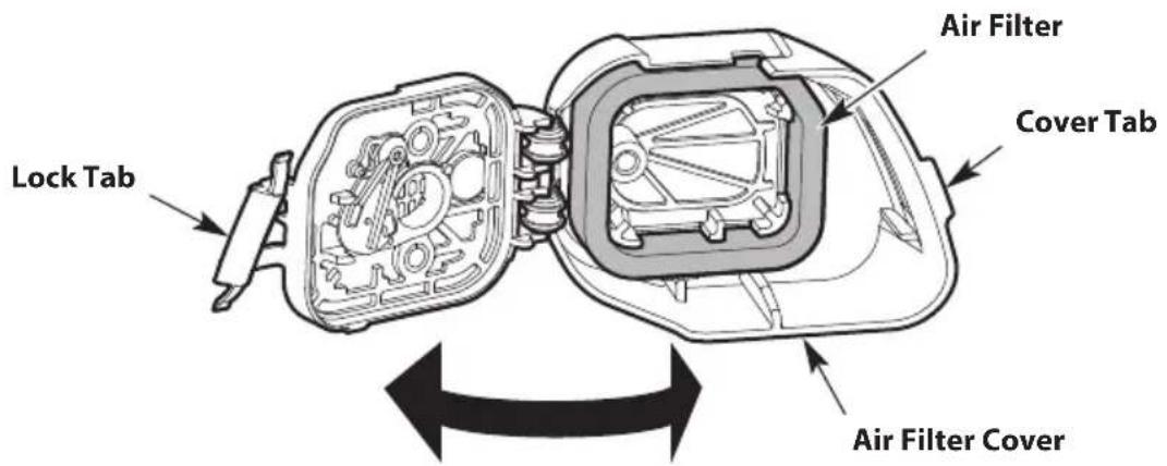
Fig. 17
ADJUSTING THE IDLE SPEED

WARNING: The blade may spin during idle speed adjustments. Wear protective clothing and observe all safety instructions to prevent serious personal injury.
If the engine will not idle properly:
- Start the engine. Refer to Starting and Stopping.
- Release the throttle control and let the engine idle.
- If the engine stops, increase the idle speed. Use a small Phillips screwdriver to turn the idle speed screw clockwise, 1/8 of a turn at a time, until the engine idles smoothly (Fig. 18).
- If the blade spins when the engine idles, reduce the idle speed. Turn the idle speed screw counterclockwise, 1/8 of a turn at a time, until the blade stops moving (Fig. 18).
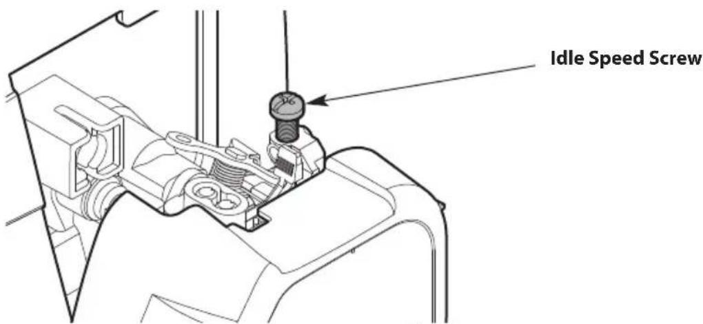
Fig. 18
MAINTAINING THE SPARK PLUG

WARNING: Do not sand blast, scrape or clean spark plug electrodes. Grit in the engine could damage the cylinder.
- Stop the engine and allow it to cool. Grasp the spark plug boot firmly and pull it from the spark plug.
- Clean around the spark plug. Remove the spark plug from the cylinder head with a 5/8-inch socket, turning counterclockwise.
- Inspect the spark plug. If the spark plug is cracked, fouled or dirty, replace it with:
• USA: replacement part #753-06847, a Champion RDJ7J or an equivalent spark plug.
• Canada: replacement part #794-00097, a Champion QDJ7J or an equivalent spark plug.
- Use a feeler gauge to set the air gap at 0.025 in. (0.635 mm) (Fig. 19).
- Install the spark plug in the cylinder head. Tighten the spark plug with a 5/8-inch socket, turning it clockwise until snug.
NOTE: If using a torque wrench, torque to:
110-120 in.·lb. (12.3-13.5 N·m). Do not over tighten.
- Reattach the spark plug boot.
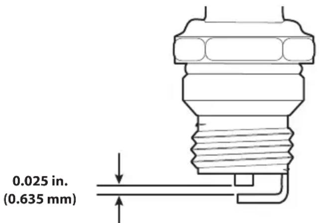
Fig. 19
CLEANING

WARNING: To avoid serious personal injury, always stop the engine and allow it to cool before cleaning or maintaining the unit.
- Use a small brush to clean the outside of the unit.
- Do not use strong detergents. Household cleaners that contain aromatic oils such as pine and lemon, and solvents such as kerosene, can damage plastic.
- Wipe off any moisture with a soft cloth.
- Clean the blade with water. Wipe the blade with a light machine oil to prevent rust.
STORAGE

WARNING: Store the unit out of the reach of children. Lock up the unit to prevent unauthorized use or damage.

WARNING: Store the unit in a dry, well-ventilated area. Never store a fueled unit where fumes may reach an open flame or spark. Allow the engine to cool before storing.
- To suspend the attachment from a hook, install the hanger cap onto the attachment. Make sure the release button is securely locked into one of the holes on the hanger cap.
Short-term Storage (1-2 weeks)
- Store the unit in a horizontal position. If this is not possible, store the unit vertically with the engine at the top.
Long-term Storage
- Remove the fuel cap, tip the unit and drain the fuel into an approved container. Reinstall the fuel cap.
- Start the engine and allow it to run until it stalls. This ensures that all fuel has been drained from the carburetor.
- Allow the engine to cool. Remove the spark plug and put 5 drops of any high-quality motor oil or 2-cycle oil into the cylinder. Pull the starter rope slowly to distribute the oil. Reinstall the spark plug.
- Thoroughly clean the unit and inspect it for any loose or damaged parts. Repair or replace damaged parts and tighten loose screws, nuts or bolts.
Preparing the Unit for Use after Long-term Storage
- Remove the spark plug. Tip the unit and drain all of the oil from the cylinder into an approved container. Reinstall the spark plug.
NOTE: Do not use fuel that has been stored for more than 30 days. Dispose of old fuel and oil according to federal, state and local regulations.
TROUBLESHOOTING
PROBLEM SOLUTION
THE ENGINE WILL NOT START
| The fuel tank is empty Fill the fuel tank with properly-mixed fuel | |
| The primer bulb was not pressed enough Press the | primer bulb 10 times or until fuel is visible |
| The engine is flooded | Move the choke lever to Position 3, press the throttle lockout, squeeze the throttle control and pull the starter rope until the engine starts |
| The fuel is old (over 30 days) and/or improperly mixed | Drain the fuel tank and add fresh, properly-mixed fuel |
| The spark plug is fouled Replace the spark plug | |
THE ENGINE WILL NOT IDLE
| The air filter is dirty Clean or replace the air filter | |
| The fuel is old (over 30 days) and/or improperly mixed | Drain the fuel tank and add fresh, properly-mixed fuel |
| The idle speed is incorrect Adjust the idle speed |
THE ENGINE WILL NOT ACCELERATE
| The fuel is old (over 30 days) and/or improperly mixed | Drain the fuel tank and add fresh, properly-mixed fuel |
| The blade is bound with grass Stop the engine and clean the blade | |
| The air filter is dirty Clean or replace the air filter | |
THE ENGINE LACKS POWER OR STALLS
| The fuel is old (over 30 days) and/or improperly mixed | Drain the fuel tank and add fresh, properly-mixed fuel |
| The air filter is dirty Clean or replace the air filter | |
| The spark plug is fouled Replace the spark plug |
If further assistance is required, contact an authorized service center.
TABLE DES MATIÈRES
Sécurité....34
Fig. 3
INSTALLATION ET RÉGLAGE DE LA POIGNÉE
INSTRUCTIONS D'ARRÊT
natural_image
Technical line drawing of a mechanical component with no visible text or symbolsPosition 3 Position 2
Poire d'amorçage
Fig. 7
INSTRUCTIONS D'ARRÊT
natural_image
Technical line drawing of a mechanical assembly with no visible text or symbolsnatural_image
Line drawing of a person using a power tool to clean or manage equipment on a curved surface (no text or symbols)Fig. 10
CONSEILS POUR OBTENIR LES MEILLEURS RÉSULTATS
natural_image
Technical line drawing of a mechanical assembly with no visible text or symbolsnatural_image
Line drawing of a person using a lawn power saw to clean or manage equipment (no text or symbols)Fig. 10
natural_image
Technical line drawing of a mechanical assembly with a bolt and housing (no text or symbols)769-26349-00



- SAVE THESE INSTRUCTIONS
- SAFETY
- SYMBOL MEANING
- SPARK ARRESTOR NOTE
- - IMPORTANT SAFETY INSTRUCTIONS
- READ ALL INSTRUCTIONS BEFORE OPERATING
- WARNING: Gasoline is highly flammable and its vapors can explode if ignited. Take the following precautions:
- WHILE OPERATING
- EDGER SAFETY
- OTHER SAFETY WARNINGS
- SAFETY & INTERNATIONAL SYMBOLS
- APPLICATIONS (AS AN EDGER)\*
- ASSEMBLY TOOLS REQUIRED
- SPECIFICATIONS\*
- ASSEMBLY
- INSTALLING AND REMOVING THE ATTACHMENT
- Installing the Attachment
- Removing the Attachment
- INSTALLING AND ADJUSTING THE HANDLE
- (Handle Type A or B)
- Installing the Handle
- Adjusting the Handle
- OIL AND FUEL
- OIL AND FUEL MIXING INSTRUCTIONS
- Definition of Blended Fuels
- Using Blended Fuels
- CAUTION: DO NOT USE E85 FUEL IN THIS UNIT.
- Using Fuel Additives
- Mixing the Fuel
- FUELING THE UNIT
- STARTING AND STOPPING
- STARTING INSTRUCTIONS
- Before Starting the Unit
- Starting the Unit
- PRIME:
- NOTE: Continue to SQUEEZE and HOLD the throttle lockout and the throttle control for ALL further steps.
- START:
- STOPPING INSTRUCTIONS
- USING THE ELECTRIC START ACCESSORY
- OPERATION
- HOLDING THE UNIT
- TIPS FOR BEST RESULTS
- ADJUSTING THE CUTTING DEPTH
- MAINTENANCE
- MAINTENANCE SCHEDULE
- REPLACING THE BLADE
- Removing the Blade
- Installing the Blade
- MAINTAINING THE AIR FILTER
- Cleaning the Air Filter
- ADJUSTING THE IDLE SPEED
- MAINTAINING THE SPARK PLUG
- CLEANING
- STORAGE
- Short-term Storage (1-2 weeks)
- Long-term Storage
- Preparing the Unit for Use after Long-term Storage
- TROUBLESHOOTING
- PROBLEM SOLUTION
- TABLE DES MATIÈRES
- INSTALLATION ET RÉGLAGE DE LA POIGNÉE
- INSTRUCTIONS D'ARRÊT
- CONSEILS POUR OBTENIR LES MEILLEURS RÉSULTATS
Brand : TROY-BILT
Model : TBE252
Category : String Trimmer