
296421 - Oven BARTSCHER - Free user manual and instructions
Find the device manual for free 296421 BARTSCHER in PDF.


| Product type | Electric oven with infrared ceramic glass hob for professional gastronomy |
| Power supply | 230 V 3~ / 380-415 V 3N~, 50/60 Hz |
| Oven temperature range | 70 °C to 300 °C |
| Oven functions | Static oven with top, bottom or both elements selectable via switch |
| Controls | Temperature regulator for hob, oven thermostat, oven switch, indicator lights (power, heating, safety) |
| Safety devices | Safety thermostat for oven and hob, residual heat indicator (temperature >70 °C), mandatory safety circuit breaker |
| Hob cleaning | Use a sponge and neutral cleaning product; remove persistent residues with a cloth soaked in water and cleaning product overnight |
| Oven cleaning | Remove the bottom and slides; clean with suitable products; do not use direct water jet |
| Stainless steel maintenance | Do not use steel wool or iron brush; apply vaseline oil if not used for a long time |
| Installation | Minimum distance of 10 cm from walls (50 cm if oven), series installation possible, floor fixing required |
| Electrical connection | By a qualified technician; use H07RN-F cable or better; safety circuit breaker with contact opening for overvoltage category III |
| Spare parts and repairability | Replace worn components with original spare parts; service intervention reserved for a service technician |
| Compliance | IEC EN 60335-1 and 60335-2-36; CE marking; WEEE directive |
Frequently Asked Questions - 296421 BARTSCHER
User questions about 296421 BARTSCHER
0 question about this device. Answer the ones you know or ask your own.
Ask a new question about this device
Download the instructions for your Oven in PDF format for free! Find your manual 296421 - BARTSCHER and take your electronic device back in hand. On this page are published all the documents necessary for the use of your device. 296421 by BARTSCHER.
USER MANUAL 296421 BARTSCHER
natural_image
Two stainless steel kitchen appliances: one with a flat-screen stove and the other with a pan containing food inside (no visible text or symbols)INSTALLATIONS-, BEDIENUN GS-UND W ARTUN GSANW EISUNGEN
INSTALLATION, OPERATING AND MAINTENANCE NST RUCTIONS
MANUEL D'INSTALLATION, D'UTILI SATIO N ET D'E NTRETIEN
natural_image
Close-up of a ceiling-mounted electronic device with two circular components, labeled [A] in the top left corner (no other text or symbols visible)5. GEBRAUCH UND FUNKTION
natural_image
Mechanical component diagram showing two circular components with a dashed arrow labeled 'V' pointing to a horizontal line (no text or symbols beyond the label)natural_image
Close-up of two black circular mechanical components with a dashed arrow indicating alignment or adjustment (no text or symbols visible)natural_image
Three identical cooking pots with different liquid levels and a crossed-out baking pan (no text or symbols)natural_image
Technical line drawing of an oven with a grating and labeled component A (no text or symbols beyond labels)natural_image
Pure technical diagram of a mechanical component with no text, numbers, or symbolsnatural_image
Diagram of a mechanical component with directional arrows and a labeled point B (no text or symbols beyond labels)
natural_image
Diagram of a mechanical assembly with two bolts and a stepped component, showing directional arrows (no text or symbols)
natural_image
Technical line drawing of a mechanical device with labeled component A (no text or symbols beyond label)DEUTSCH
natural_image
3D diagram of a box with circular tops and a dashed line labeled 'A' pointing to the side (no text or symbols on the box itself)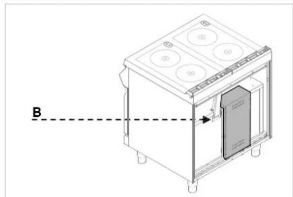
natural_image
Technical line drawing of a microwave oven with labeled component B (no text or symbols beyond label)Äquipotentialklemme
Symbole
natural_image
Technical line drawing of a kitchen appliance with a warning symbol and dashed line indicating safety (no text or labels)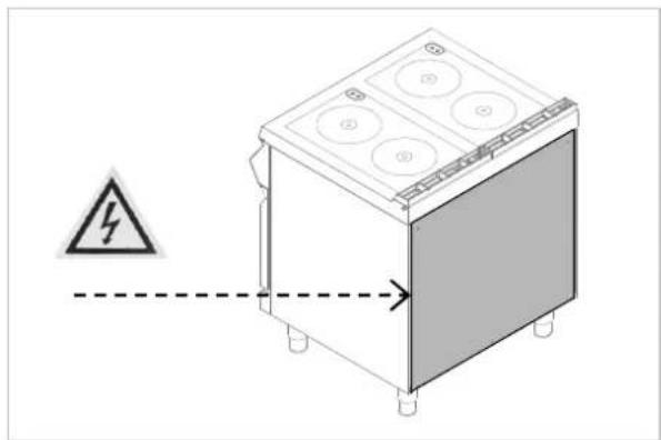
natural_image
Diagram of a kitchen appliance with a warning symbol and dashed line indicating safety (no text or labels)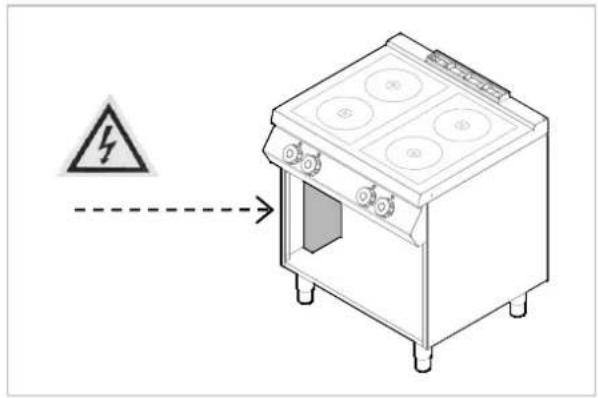
- TABLE OF CONTENTS .... 1
- INDEX 2
- SAFETY 3
- GENERAL INFORMATION AND WARNINGS.... 4
4.1. General guidelines .... 4
4.2. Description of the appliance 4
4.3. Index plate 5
4.4. Exchange of components (service technician) 5
4.5. Protection devices 5
- USE AND OPERATION 6
5.1. Description of the use the device....6
5.2. Heating plate switching on and off 7
5.3. Oven switching on and off 8
5.4. Guidelines on how to use the appliance 8
- CLEANING AND MAINTENANCE 9
6.1. Guidelines on cleaning and maintenance 9
6.2. Correct maintenance 9
6.3. Cleaning of ceramic plate....10
6.4. Cleaning of the oven 10
-
PROBLEMS DURING OPERATION 11
-
INSTALLATION 11
8.1. Packaging and unpacking 11
8.2. Installation (service technician) 12
8.3. Installation of the appliance in a line 13
8.4. Connection to the mains (service technician) 13
8.5. Check-up (service technician) 15
- APPLIANCE DISPOSAL 16
ATTACHMENTS......I
2. INDEX
A
APPLIANCE DISPOSAL 16
C
Check-up 15
Cleaning of ceramic plate 10
Cleaning of the oven 10
Connection to the mains 13
Correct maintenance 9
D
Description of the appliance 4
Description of the use the device 6
E
Exchange of components 5
G
General guidelines 4
Guidelines on cleaning 9
Guidelines on how to use the appliance 8
Guidelines on regular use of the appliance 8
H
Heating plate switching on and off 7
Heating plates - safety thermostat 5
|
Index plate 5
Installation 12
Installation of the appliance in a line 13
L
Longer interval in the use of the appliance 8
M
Maintenance 9
0
Oven - safety thermostat 5
Oven switching on and off 8
P
Packaging 11
PROBLEMS DURING OPERATION 11
Protection devices 5
R
Residual heat indicator light. 6
s
SAFETY 3
U
Unpacking 11
3. SAFETY

Read carefully the guidelines and uctions in the instruction manual e you use the appliance.
The instruction manual contains general information on how to safely use and maintain the appliance. Retain the manual for future reference.

Electric installation conforms to CEI EN 5-1 and 60335-2-36 regulation.

To prevent any hazard, the damaged power cable may be replaced by the facturer or service personnel only.
The manufacturer took extra care when designing and manufacturing to prevent any safety or health hazard to the personnel operating the appliance.
Please read carefully the guidelines in the instruction manual and instructions placed directly onto the appliance. Above all, observe all the safety instructions.
Do not intervene in or remove the protective devices installed in the appliance. Non-compliance may lead to severe safety and health hazard against people. We recommend to perform a few tests to know the layout and main functions of the control panel, particularly those to switch the appliance on and off.
The appliance is intended only for the use it has been designed for and any other use is considered as the use not in compliance with the intended use.
The manufacturer is not liable for material damage or damage to person caused by misapplication or incorrect application of the appliance.
Any maintenance work that requires special technical license or special skills may be performed by qualified personnel only.
To provide hygiene and protect foods from dirt, all the elements that have direct or indirect contact with the foods and all border areas must be thoroughly cleaned. Use only the cleaning agents intended for use in contact with food and avoid using flammable agents or harmful to health.
After each use of the appliance make sure that all the heating elements and control elements have been switched off and the cable unplugged.
In case of prolonged interval in using the appliance disconnect all power supply cables and thoroughly clean the inside and outside elements of the appliance.

In direct connection to the mains safety switch should be supplied by wire joints dilation is large enough of pure disconnection in category III voltage, which is in accordance with installation rules.

The device requires some safety sures during installation, positioning, and connecting to the power supply (on 8 "INSTALLATION").

Do not clean the device with direct of water.

When the cooker surface is cracked, diately disconnect it from the power by.

Do not place any plastic containers on surface of the cooker.

Avoid using the aluminium foil for acting the surfaces during the deviceation.
4. GENERAL INFORMATION AND WARNINGS
4.1. General guidelines
The manual has been edited by the manufacturer to provide the authorized personnel with the information necessary to work with the appliance. We recommend the intended readers to read the manual carefully and comply with the information. By reading the information contained in the manual, hazards against people health and safety may be prevented.
Retain the manual in an easily available place throughout the time of use of the appliance to have access and refer to the required information at any time.
Special symbols, described below, have been used to stress important information or draw attention to essential data:
Warning

Indicate important safety instructions. You should acquire the proper conduct to prevent hazard against people health and safety or not to cause any damage.
Caution

Indicate essentials technical data that you cannot ignore.
4.2. Description of the appliance
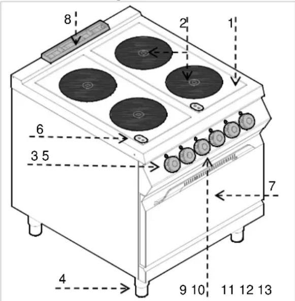
The electric cooker with infrared ceramic heating plate has been designed and manufactured for preparing and cooking of food products in the professional gastronomy sector.
1) Cooker: with ceramic heating plate and infrared heating coil;
2) Hob;
3) Temperature controller: adjusts power of electric heating plate;
4) Feet of adjustable height;
5) Power supply indicator light: indicates activation of supply voltage.
6) Heating plates indicator light: Indicates activation of the heating plates and is on when their temperature exceeds 50^ C
7) Electric oven (static);
8) Oven smoke extraction;
9) Oven thermostat controller: adjusts temperature of the electric oven
10) Oven switch: turns on or off the oven heating coils.
11) Thermostat indicator light: indicates activation of the safety thermostats.
12) Power supply indicator light: indicates activation of supply voltage.
13) Temperature indicator light: indicates oven heating.
4.3. Index plate
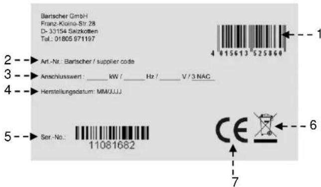
The index plate indicated in the drawing is mounted directly onto the appliance. There are all guidelines and information on the plate required for safe use.
1) EAN-No.
2) Code-No. / Model-No.
3) Connection: power / supply frequency / supply voltage
4) Date of production
5) Serial-No.
6) WEEE symbol
7) CE-marking
4.4. Exchange of components (service technician)

Before exchange of the component
switch on all the existing protection devices.

In particular, switch off the electric supply with the electrical potential switch. If necessary, exchange the used components to the original spare parts.

We are not liable for personal injury or damage to the components that arise due to application of other spare parts than original or intervention into the appliance without the manufacturer's consent that may have altered the safety requirements.
4.5. Protection devices
The device is equipped with the following protection systems:
-
Heating plates - safety thermostat: It is the device inside each heating plate which reduces power in case of overheating. When the reason is removed and temperature drops, the operation is automatically restored.
-
Oven - safety thermostat: Cuts off the oven power supply in case of overheating.
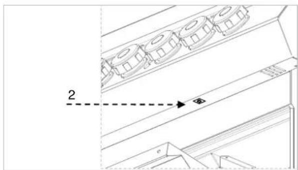
Safety thermostat activation is indicated by appropriate indicator light. Figure shows position (2) of oven safety thermostats.
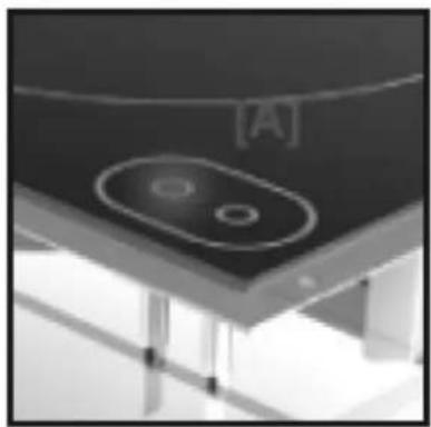
The ceramic cooker is equipped IN STANDARD with RESIDUAL HEAT INDICATOR LIGHT on the cooker, which indicates that temperature of the cooking surfaces exceeds 70°C and warns the user to NOT TO TOUCH the cooking surfaces to avoid burns. The indicator light becomes on after few minutes from the activation of cooker heating coils and remains on during the normal operation. After deactivation of the heating plates it remains on until the temperature drops below 50°C.

Keep in mind that in case of sudden supply failure there is the risk of as the cooking surfaces may be still

Check every day that the protection es are mounted correctly and ional.
natural_image
Interior ceiling view with a circular recessed component and a labeled section [A] (no text or symbols on the object itself)5. USE AND OPERATION
5.1. Description of the use the device.
The elements controlling the essential functions are located on the control panel of the device.
A) Temperature controller: adjusts power of electric heating plates
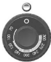
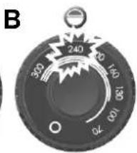
B) Oven thermostat controller: adjusts temperature of the electric oven
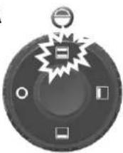
C) Oven switch: activates upper, lower, or both heating coils.
D) Green indicator light: indicates activated power supply
E) White indicator light: indicates oven heating
F) Red indicator light: indicates activation of safety thermostats.
G) Indicator light of heating plates: indicates activation of electric heating plates.


5.2. Heating plate switching on and off
During the first activation leave the heating plates for heating without pots.
A) Start the automatic switch-off to turn on the electrical connection.
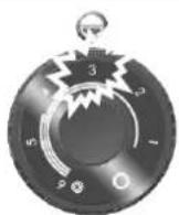
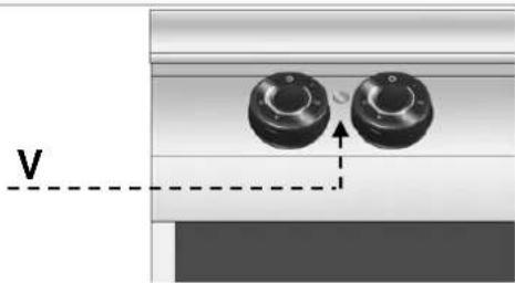
B) Turn the temperature controller to position 1 to set the heating plate to minimum power. The green control light (V) will come on.
C) Then turn the temperature controller to desired position.

Pos 0
Pos A
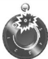
D) Turn the temperature controller to position A to set the heating plate to maximum power.
E) Turn the temperature controller to position 0 to switch off the heating plate. The green control light (V) will go off.
F) Start the automatic switch-off to turn off the electrical connection, when needed.
natural_image
Mechanical component diagram showing two circular components with a dashed arrow labeled 'V' pointing to one (no text or symbols beyond label)5.3. Oven switching on and off
A) Start the automatic switch-off to turn on the electrical connection.
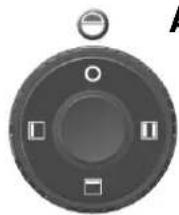
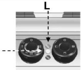
B) Turn switch A to activate the oven heating coils. The green control light (L) will come on.
C) Turn the oven temperature controller and set it between 70°C and 300°C.
When the heating coils are activated, the white indicator light (W) will come on.
When the oven reaches required temperature the white indicator light goes off.
D) Turn switch (A) to activate or deactivate the upper, lower, or both heating coils.
E) To switch the oven off turn the switch (A) to position 0. Then turn the thermostat controller (B) to position 0.
| Temperature °C 70 | 100 130 | 160 200 | 240 270 | 300 | ||||
| Time in minutes | 1' 30" | 3' | 4' 30' | 6' | 8' | 11' | 14' | 17' |
Pos 0
A
Pos 1
Pos 0
Pos 1
natural_image
Close-up of two circular mechanical components with a dashed arrow pointing to one (no text or symbols visible)5.4. Guidelines on how to use the appliance
Longer interval in the use of the appliance
When you plan not to use the appliance for the prolonged time, follow the instructions below:
- Turn on the automatic switch-off to disconnect from the mains;
- Thoroughly clean the appliance and surrounding areas;
- Apply the vaseline oil on the stainless steel surfaces;
- Perform all maintenance works.
Guidelines on regular use of the appliance
To ensure correct use of the device follow the guidelines below:
➢ Use only accessories provided by the manufacturer;
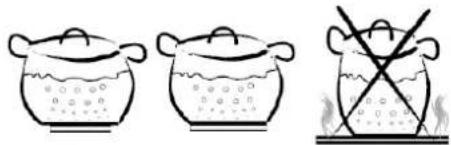
Use the heating plates only for heating pots, do not heat food products directly on the plates.
The device and its vicinity should be always kept clean.
➢ Use containers of diameter not lower than diameter of the heating plates.
natural_image
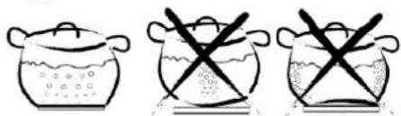
Illustration of two cooking pots with liquid and a crossed-out pot (no text or symbols)➢ Use only pots with flat bottom.
natural_image
Three identical illustrations of cooking pots with crossed-out black X marks, no text or symbols present.Cast iron steak frying pans and other metal alloys are not suitable for use on the ceramic cooker as high bottom thickness may cause dangerous heat concentration on the cooker. Besides, rough bottom may scratch the surface and the metal alloy may leave permanent stains.
Use only food grade cleaning agents.
▶ Check if the oven door is properly installed.
▶ Heat the oven before use.

Do not use the oven with partially d door.
In order to brown the product surface put in on the upper grill and switch the upper coil on.

Do not use the heating plates without pots. Switch the heating plate off when not in use.

Avoid using the aluminium foil for tting the surfaces during the device ion.
Before putting the pots on the cooker clean and dry their bottoms. Corrugated bottoms of pots and frying pans may leave marks and grooves when moved on the cooker.
6. CLEANING AND MAINTENANCE
6.1. Guidelines on cleaning and maintenance

Before you start maintenance works, turn on all the mounted protective devices.
In particular, disconnect the electric power supply by means of the automatic switch-off.
6.2. Correct maintenance
Proper maintenance includes daily cleaning of all components which have contact with food products, and regular maintenance of drain pipes.
Careful maintenance ensures the best performance, longer life of the appliance and proper operation of the protective devices.
Never direct the water stream or high pressure jet towards the appliance.
To clean the stainless steel, do not use iron wool or iron brush as they may leave iron particles on the surface that form rust in result of oxidation.
In the case of prolonged intervals in the use of the appliance, apply the vaseline oil onto all the stainless steel surfaces.

Do not use any clearing agents that in substances hazardous or harmful lth (solvents, petrol. etc.).
At the end of the working day clean:
▶ heating plates and oven (when used)
device.
Regularly instruct the specialist personnel to perform the following maintenance works:
check the electric installation;
▶ check the safety thermostats.
6.3. Cleaning of ceramic plate
Follow the instructions below:
➢ Turn off the heating plates and leave to cool down.
➢ Start the automatic switch-off to turn off the electrical connection.
➢ Thoroughly clean the heating plate with use of sponge and neutral cleaning agent.
➢ Deposits and stains must be removed quickly, best when the plate is still warm.
➢ Wash the cooking surface with clean water and dry.

Do not direct the water jet on the heating plate, particularly when it is still hot.

Do not pour water directly heating plate.

Do not use any abrasive cleaning as they may scratch the surface.

In order to remove stubborn stains the cooker may be covered with cloth soaked in the cleaning agent for the night. Repeat cleaning the next day.
6.4. Cleaning of the oven
When the oven is cold remove bottom and guides. After cleaning switch the empty oven to avoid corrosion.
Follow the instructions below:
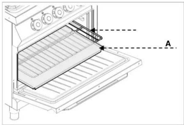
Remove the oven bottom (A) and grill (B) and clean them thoroughly.
Clean the oven interior from any burnt residuals which may disturb correct operation.
➢ Clean the surface and replace the oven elements.
7. PROBLEMS DURING OPERATION
The information below is provided to recognize and repair any failures that may occur when operating the appliance.
Some of the failures can be repaired by the user, others require thorough specialist knowledge. Such problems may be solved exclusively by the qualified personnel.
| Problem Cause Solution | ||
| The heating plates do not work. | The electrical connection is not correct. | Check connection of supply cable. ✘ Contact the service company. |
| Activation of temperature limiter. | Wait until the thermostat in the heating plates restores normal operation. | |
| Damaged energy controller. | Replace the part. ✘ Contact the service company. | |
| The heating plates remain hot. Damaged heating plate. | When problem persists contact the service company. | |
| The oven heating coils do not work. | The electrical connection is not correct. | Check connection of supply cable. ✘ Contact the service company. |
| Activation of temperature limiter. | Wait for the oven to cool down. Then reset the thermostat (see special section). | |
| Damaged switch. | Replace the part. ✘ Contact the service company. | |
| The oven does not reach the preset temperature. | Damaged operational thermostat. | Replace the part. ✘ Contact the service company. |
8. INSTALLATION
8.1. Packaging and unpacking
During unloading and when installing the appliance follow the information from the manufacturer placed directly on the packaging and in this manual.
To lift and transport the product plan to use a fork lift or stacker, and pay attention to even weight distribution to avoid a risk of tilting of the packaging (avoid excessive incline!).
When using the lifting equipment pay attention to the mains cable and discharge pipes and feet position.
The packaging consists of the carton packaging and wooden pallet. There are symbols printed on the carton packaging that according to the international agreements inform about the regulations to follow when loading and unloading, transporting and storing the appliance.

When collecting the goods check if the packaging is complete and has not been damaged during transport.
Any damage should be immediately reported to the shipping company.
Unpack the appliance as soon as possible to check if the appliance is not damaged.
Do not use a sharp object to cut the carton box. It may damage the stainless steel inside the box.
Remove the carton packaging from bottom to top.
When unpacked check if the appliance is according to the order.
In case of any difference inform the sales agent immediately.

Do not store the packaging als (nylon bags, polystyrene foam, .) in the reach of children!
Remove the protective PVC layer from the out and inner surfaces. If possible, do not use any metal tools.
8.2. Installation (service technician)
All the stages of the installation must be carefully planned.
The location should be equipped with all supply connections and production waste outlet. The location should also be properly lit and comply with all hygiene and sanitary requirements according to the binding regulations.
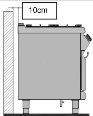
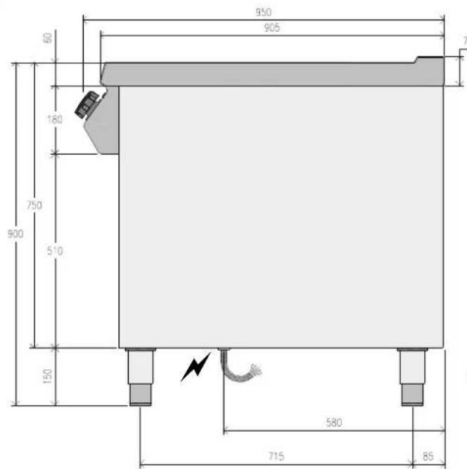
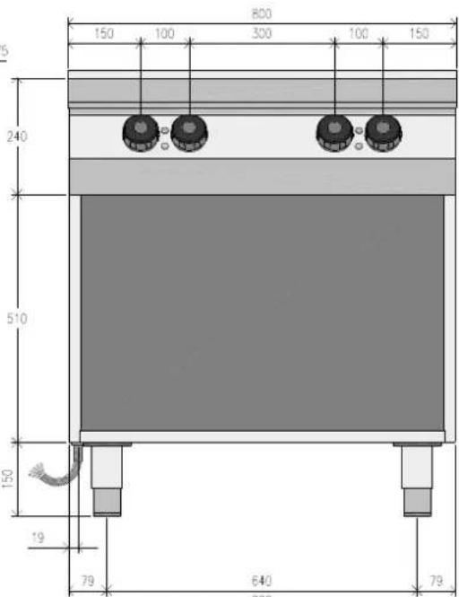
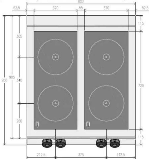
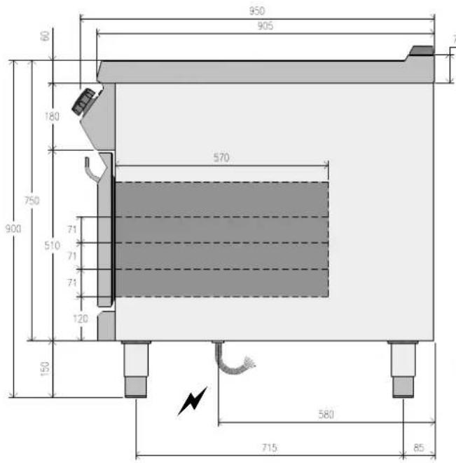
The appliance should be installed with the minimum 10 cm clearance from the wall.

The devices with the oven must be
installed at least 50 cm from the wall.
Locate the device in the horizontal position by adjusting the individual feet.

To ensure the correct operation of appliance, the appliance must be bed and operated in the thoroughly rated room only.

When the device is to be installed the walls, partitions, kitchen cabinets, native elements, etc., they must be from non-flammable materials or used with suitable non-flammable metals.
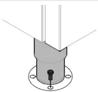
The device IR091M00 must be fixed to the floor.
natural_image
Pure technical diagram of a mechanical component with no text, numbers, or symbols8.3. Installation of the appliance in a line
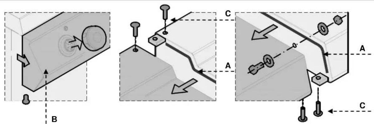
To fix the appliance in a line (neighboring) follow the steps:
-
Dismantle the control panel, and remove the cast iron frame from the chimney if necessary.
-
Apply the sealing tape (A) onto the joining sides.
-
Place the appliances next to each other and in a horizontal position (by adjusting the feet).
-
Connect the appliances with the joining elements.
8.4. Connection to the mains (service technician)
The device may be connected to the power supply only by the authorized and qualified personnel, when the valid regulations are followed and when appropriate material is used in accordance to the regulations.
Depending on the model the devices are designed for connection to the following networks:
230 V 3\~ / 380-415 V 3N\~
During the installation follow the data on the rating plate.
For direct connection to the network install the device assuring disconnection from the network, having spacing of contact large enough for disconnection in conditions of overvoltage category III, which conforms to the installation principles.
To correctly connect the device, follow the guidelines below.
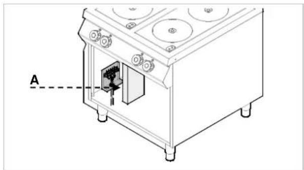
Version without the oven
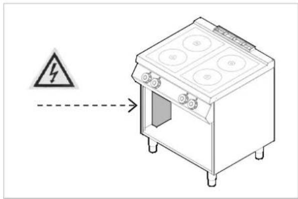
Remove the cover from the terminal strip (A).
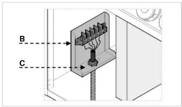
Connect the switch-off to the terminal strip (B) of the device, as shown in the drawing and block diagram (see the attachment). Use the H07RN-F cable or better.
natural_image
Technical line drawing of a mechanical device with labeled component A (no text or symbols beyond label)ENGLISH
▶ Tighten the cable endings (C).
▶ Replace the terminal strip cover.
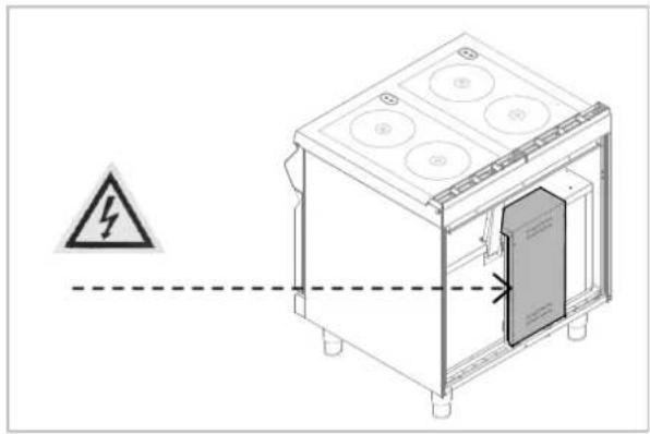
Version with the oven
Remove the cover from the terminal strip (A) (B).

natural_image
Diagram of a 3D box with circular components and a dashed line labeled 'A' pointing to the side (no text or symbols on the box itself)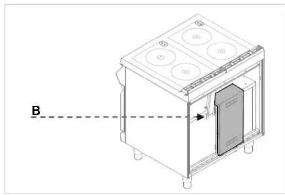
natural_image
Technical line drawing of a kitchen appliance with labeled components and a dashed line indicator (no text or symbols)Connect the switch-off to the terminal strip (C) of the device as shown in the drawing and block diagram (see the attachment). Use the H07RN-F cable or better.
▶ Tighten the cable ending (D).
➢ Replace the terminal strip cover.

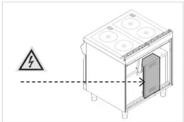
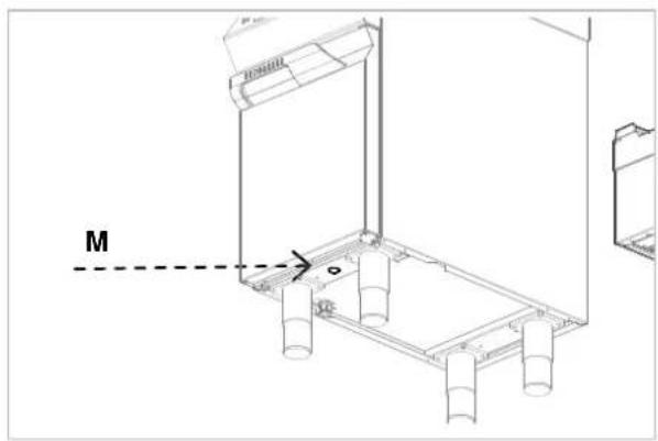
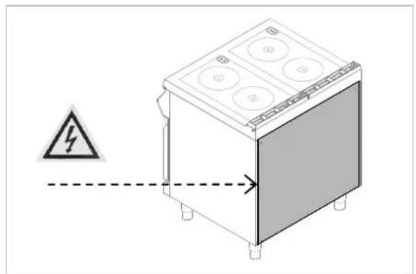
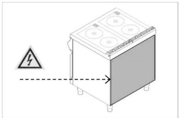
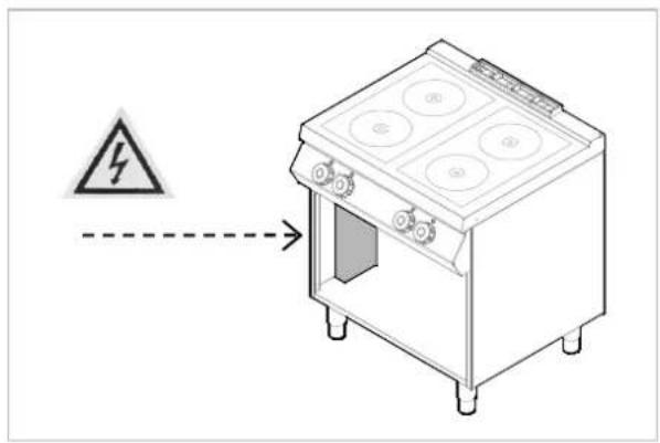
The device is equipped with the equipotential clamp (M). The terminal is marked with appropriate sticker:
Designation
The following symbol "Electric voltage hazard" indicates that there are live elements under the cover.
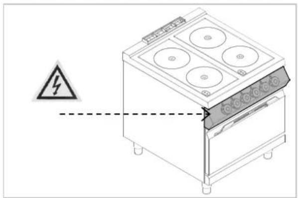

natural_image
Technical line drawing of a kitchen appliance with a warning symbol and dashed line indicating safety (no text or labels)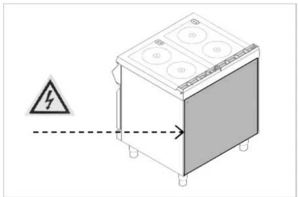
natural_image
Diagram of a kitchen appliance with a warning symbol and dashed line indicating safety (no text or labels)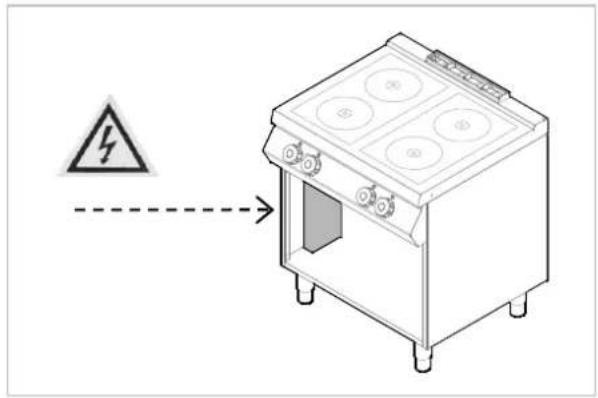
8.5. Check-up (service technician)
Before starting the appliance the installation check-up should be run to evaluate the working conditions of every single component and recognize any errors.
It is recommended to run the following check-ups:
- Check that the energy supply voltage is the same as of the appliance voltage.
- Turn on the automatic switch-off to check the electrical connections.
Check that the protection devices work correctly.
9. APPLIANCE DISPOSAL

The appliance is marked in conformity with the European Directive 2002/96/EG WASTE ELECTRICAL AND ELECTRONIC EQUIPMENT (WEEE).

By disposing the appliance in accordance with the regulations the user contributes towards prevention of adverse effects on environment and health.
The symbol on the product or attached manual indicates that the product cannot be considered as ordinary household waste and should be transferred to a special collection point for electrical and electronic appliances for recycling.
Local waste management regulations should be observed.
Further information on procedure, reusing and recycling of the product is available in local offices, waste management unit or with the product sales agent.
Bartscher GmbH
-
DYSFONCTIONNEMENTS....11
-
INSTALLATION....11
natural_image
Interior ceiling view with a circular vent and two ovals, labeled [A] in the top left corner (no other text or symbols visible)5. UTILISATION ET FONCTIONNEMENT
5.1. Description de la commande.
natural_image
Close-up of two circular mechanical components with a dashed arrow and label 'V' pointing to a horizontal line (no text or symbols on the components themselves)natural_image
Close-up of two black circular devices with control knobs and a dashed arrow indicating rotation (no text or symbols)natural_image
Illustration of three cooking pots with different sizes and a crossed-out baking pan (no text or symbols)7. DYSFONCTIONNEMENTS
natural_image
Technical diagram of a mechanical component with mounting holes and a central base (no text or symbols)natural_image
Technical line drawing of a portable electrical enclosure with labeled component A (no text or symbols beyond label)natural_image
Diagram of a kitchen appliance with labeled component A, showing front and back views (no text or symbols beyond label)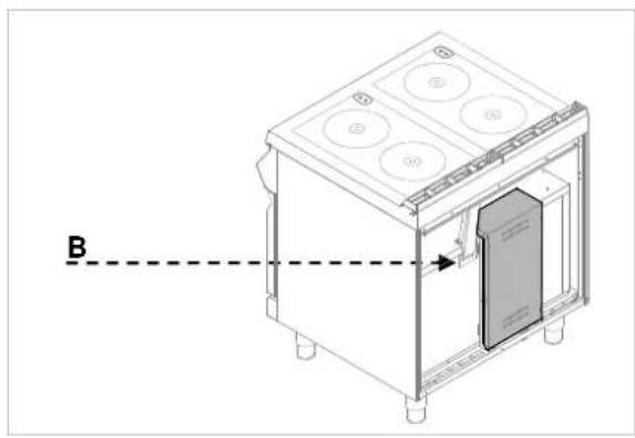
natural_image
Technical line drawing of a kitchen appliance with labeled components and a dashed line indicator (no text or symbols)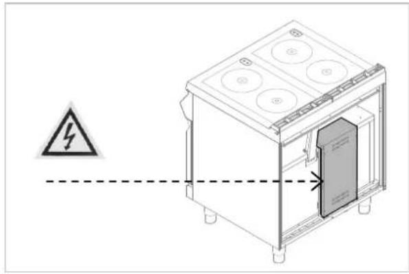
natural_image
Technical line drawing of an electrical enclosure with a warning symbol and dashed line indicating safety (no text or labels)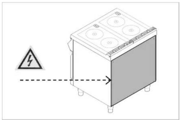
natural_image
Mechanical component diagram showing two circular components with a dashed arrow indicating direction (no text or symbols)natural_image
Close-up of two circular mechanical components with a dashed arrow pointing to one (no text or symbols visible)natural_image
Three illustrated cooking pots with different sizes and patterns: one with a lid, two with liquid, and one with a crossed-out pan (no text or symbols)natural_image
Technical line drawing of an oven with a grating and labeled component A (no text or symbols beyond labels)7. MALFUNZIONAMENTI
natural_image
Pure mechanical assembly diagram showing a cylindrical component with mounting holes and a central bolt (no text or symbols)natural_image
Technical line drawing of a portable electrical cabinet with labeled component A (no text or symbols beyond label)ITALIANO
natural_image
Diagram of a kitchen appliance with labeled component A, showing front and side views (no text or symbols beyond label)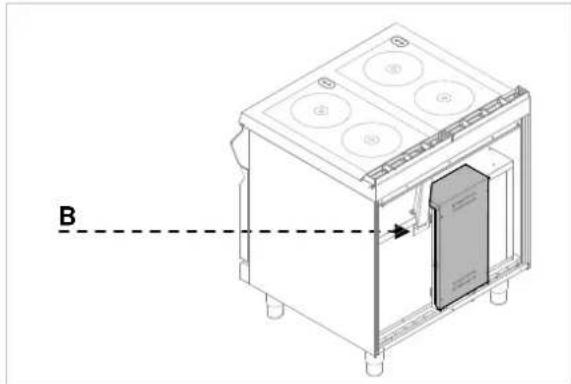
natural_image
Technical line drawing of a microwave oven with labeled components and an arrow indicating direction (no text or symbols present)Morsetto equipotenziale
natural_image
Technical line drawing of a mechanical assembly with labeled component M (no text or symbols beyond label)Indicazioni

natural_image
Diagram of a cabinet with four circular components and a warning symbol (no text or labels)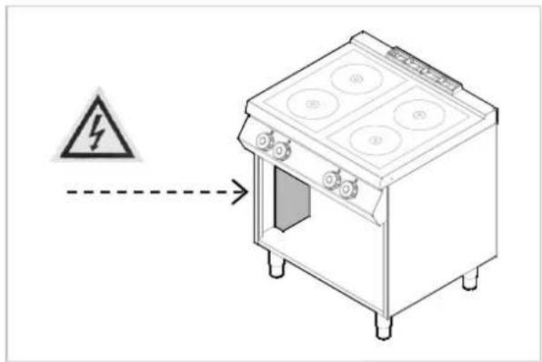
natural_image
Interior ceiling view with a circular recessed light fixture and two circular holes, labeled [A] in the top left corner (no other text or symbols visible)natural_image
Mechanical component diagram showing two circular components with a dashed arrow labeled 'V' pointing to one (no text or symbols on the components themselves)natural_image
Close-up of two circular mechanical components with a dashed arrow indicating rotation or adjustment (no text or symbols visible)natural_image
Three identical cooking pots with different sizes and patterns, one crossed out by a black cross (no text or symbols)natural_image
Pure mechanical component diagram without any text, numbers, or symbolsnatural_image
Technical line drawing of a mechanical device with labeled component A (no text or symbols beyond label)ESPAÑOL
natural_image
3D diagram of a kitchen appliance with labeled components and a dashed line marked 'A' (no text or symbols on the device itself)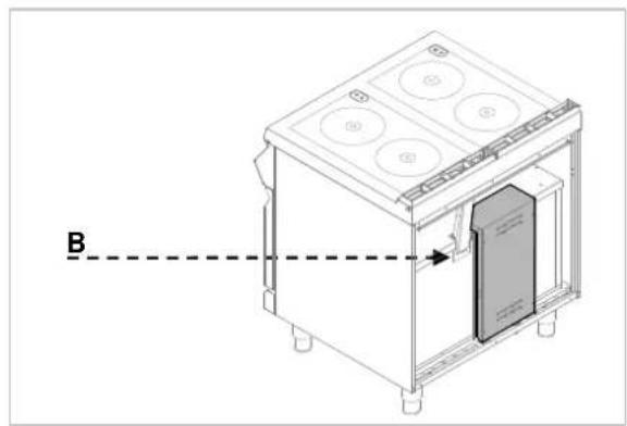
natural_image
Technical line drawing of a kitchen appliance with labeled component B (no text or symbols beyond label)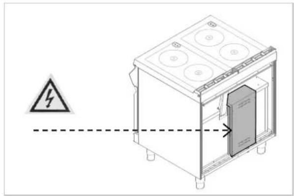
natural_image
Diagram of a kitchen appliance with a warning symbol and dashed line indicating safety (no text or labels)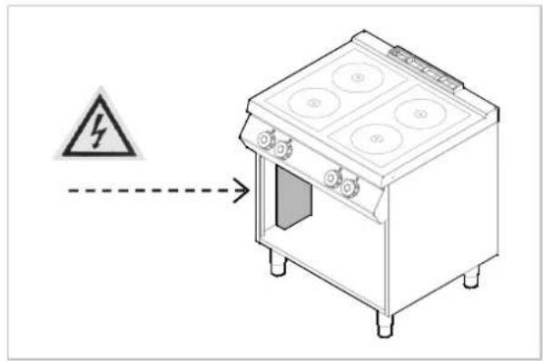
natural_image
Interior ceiling view with a circular recessed component and labeled section [A] (no text or symbols beyond label)natural_image
Mechanical component diagram showing two circular components with a dashed line labeled 'V' pointing to a dashed line (no text or symbols on the components themselves)5.3. Ligar e desligar o forno
natural_image
Close-up of two black circular mechanical components with a dashed arrow indicating rotation or adjustment (no text or symbols visible)natural_image
Three identical line drawings of a cooking pot with liquid and a crossed-out pan, no text or symbols present.natural_image
Technical diagram of an oven with internal grating and ventilation ducts, labeled A (no text or symbols beyond label)natural_image
Pure technical diagram of a mechanical component with mounting holes and a central bolt (no text or symbols)natural_image
Technical line drawing of a portable stove or oven with labeled component A (no text or symbols beyond label)PORTUGUÊS
natural_image
Diagram of a 3D box with circular components and a dashed line labeled 'A' pointing to the side (no text or symbols on the box itself)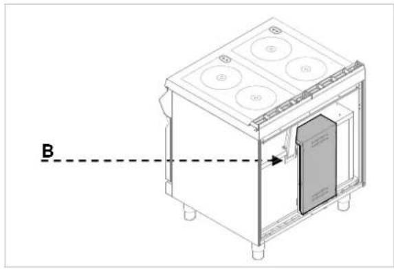
natural_image
Technical line drawing of a kitchen appliance with labeled components and a dashed line indicator (no text or symbols)
natural_image
Technical line drawing of a kitchen appliance with warning symbol and dashed line indicating safety (no text or labels)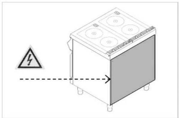
natural_image
Diagram of a kitchen appliance with a warning symbol and dashed line indicating safety (no text or labels)
natural_image
Interior view of a modern building with a ceiling-mounted display unit and two circular ovals (no text or symbols visible)natural_image
Diagram of a kitchen appliance with three control knobs and a dashed vertical line labeled A (no text or symbols on the device itself)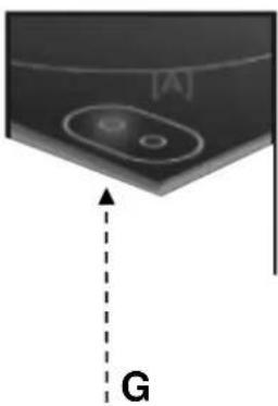
natural_image
Close-up of a device component with labeled point G and reference marker [A] (no text or symbols beyond labels)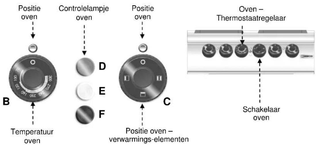
natural_image
Diagram showing two circular components with a dashed arrow labeled 'V' pointing to a horizontal line (no text or symbols beyond the label)natural_image
Close-up of two circular mechanical components with a dashed arrow pointing to a section, no visible text or symbols.natural_image
Three identical cooking pots with different liquid levels and a crossed-out baking pan (no text or symbols)natural_image
Technical diagram of an oven with internal grating and ventilation ducts, labeled A (no text or symbols beyond label)7. STORING IN DE WERKING
natural_image
Pure technical diagram of a mechanical component with no text, numbers, or symbolsnatural_image
Technical line drawing of a mechanical device with labeled component A (no text or symbols beyond label)NEDERLANDS
natural_image
Diagram of a 3D box with circular components and a dashed line labeled 'A' pointing to the side (no text or symbols on the box itself)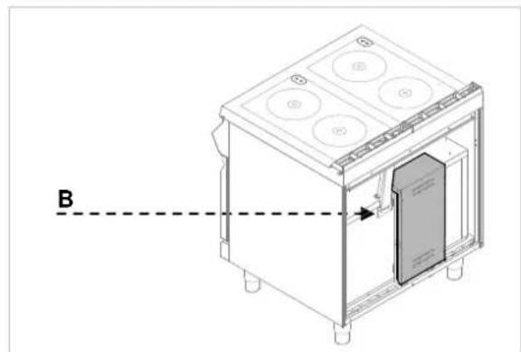
natural_image
Technical line drawing of a kitchen appliance with labeled components and a dashed line indicator (no text or symbols present)Equipotentiaalklem
Markering

8.5. Controle (onderhoudsmonteur)
natural_image
Interior view of a modern building ceiling with a circular pendant light (no text or symbols visible)5. UŻYWANIE I DZIAŁANIE
5.1. Opis obsługi.
natural_image
Close-up of two circular mechanical components mounted on a metallic surface, with a dashed arrow labeled 'V' pointing to a specific component (no text or symbols beyond the label)natural_image
Close-up of two circular mechanical dials with arrows indicating motion or movement, no visible text or symbolsnatural_image
Three identical illustrations of a cooking pot with liquid and a crossed-out pan (no text or symbols)natural_image
Three identical cooking pots with crossed-out black marks, no text or symbols present7. ZAKŁÓCENIA DZIAŁANIA
natural_image
Pure mechanical assembly diagram showing a central component with mounting holes and connecting rods (no text or symbols)natural_image
Technical line drawing of a portable electrical cabinet with labeled component A (no text or symbols beyond label)POLSKI
natural_image
Diagram of a 3D box with circular components and a dashed line labeled 'A' pointing to the side (no text or symbols on the box itself)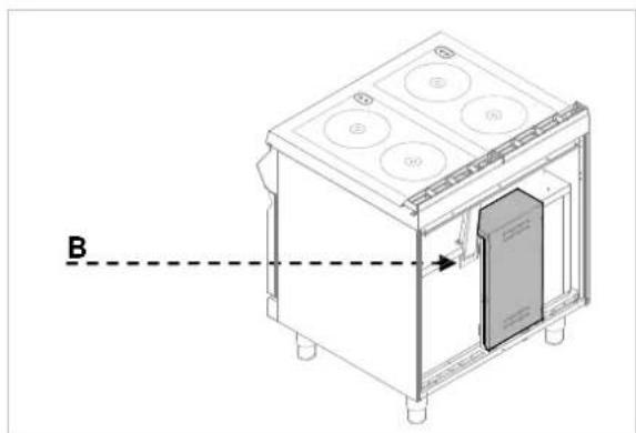
natural_image
Technical line drawing of a kitchen appliance with labeled component B (no text or symbols beyond label)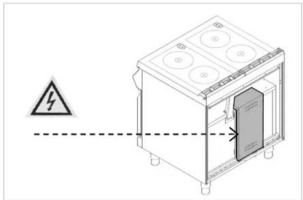
natural_image
Technical line drawing of a kitchen appliance with a warning symbol and dashed line indicating safety (no text or labels)
natural_image
Diagram of a kitchen appliance with a warning symbol and dashed line indicating safety (no text or labels)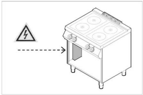
8.5. Kontrola (technik serwisu)
natural_image
Two circular white rings on a gray background, labeled '2 x 4,0 kW t' at bottom (no other text or symbols)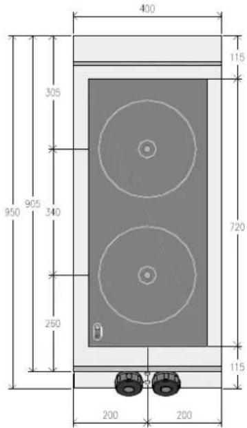
| Elektroanschluss | 8 kW | |
| Electric Connection | ||
| Branchement Electrique | ||
| Allacciamento Elettrico | ||
| Conexión elétrica | ||
| Ligação Elétrica | ||
| Elektrische aansluiting | ||
| Przyłącze elektryczne |

natural_image
Two concentric circles with a small icon in the bottom-left corner (no text or symbols)2 × 4,0 kW
| Elektroanschluss | 16 kW | |
| Electric Connection | ||
| Branchement Electrique | ||
| Allacciamento Elettrico | ||
| Conexión elétrica | ||
| Ligação Elétrica | ||
| Elektrische aansluiting | ||
| Przyłącze elektryczne |

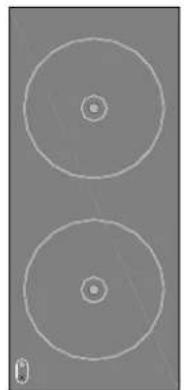
natural_image
Two concentric circles with small inner circles, no text or symbols present2 × 3500kWatt

| Elektroanschluss | 21,6 kW | |
| Electric Connection | ||
| Branchement Electrique | ||
| Allacciamento Elettrico | ||
| Conexión elétrica | ||
| Ligação Elétrica | ||
| Elektrische aansluiting | ||
| Przyłącze elektryczne |

| ALIMENTAZIONEFEED | 380-415V 3N~ 50/60Hz | LV = LAMPADA VERDEGREEN LIGHT | SIGNAL LUX Mod 21.3 230V(T120) Silicon Leads |
| K1,K2=RELE'RELE | FINDER 62.83.8.230.0300 3NO=3mm | R1,R2 = RESISTENZHEATER | ø280 1.333x3-4000W 230V |
| M=MORSETTIERATERMINAL | FV122 6 POLI - 40 A - 450 V | CABLAGGIOCABLE | CAVO H05SJ-KSection 1.5 mmq |
| B1,B2 = COMMUTATORESWITCH | 50.55071.10013A 230V | CABLAGGIO LAMPADELIGHT CABLE | CAVO H05SJ-KSection 0.75 mmq |
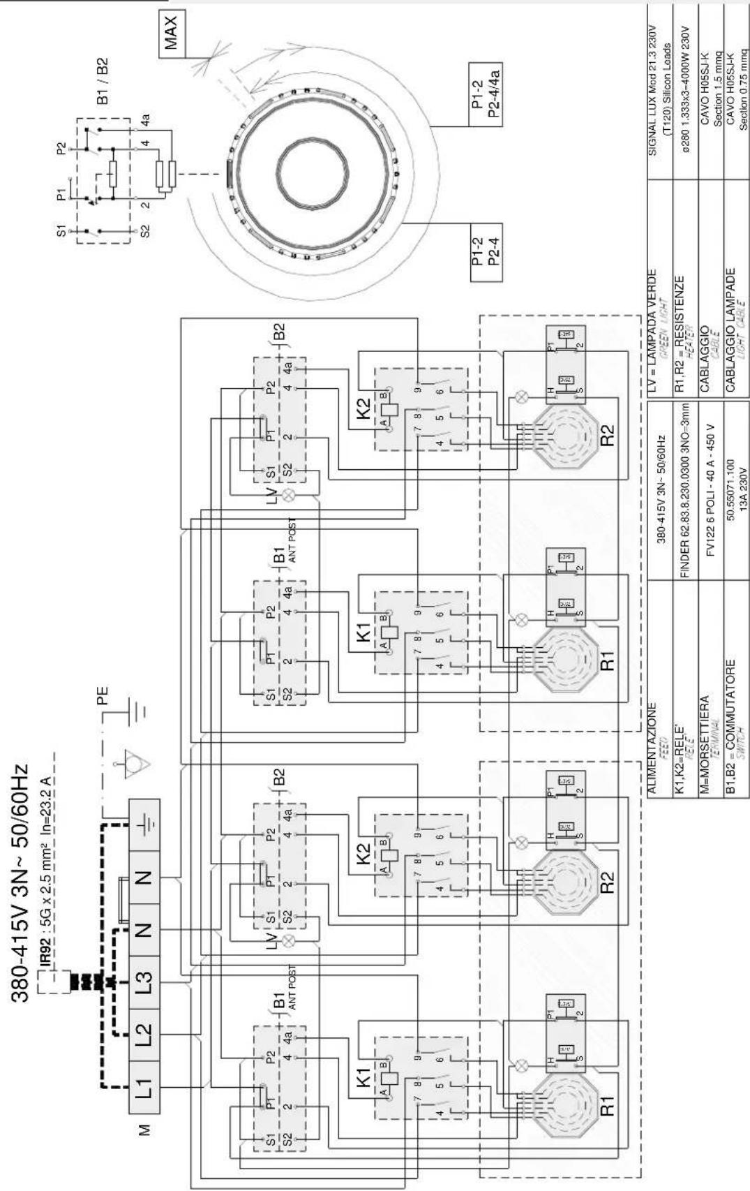
| ALIMENTAZIONEFEED | 380-415V 3N~ 50/60Hz | LV = LAMPADA VERDEGREEN LIGHT | SIGNAL LUX Mod 21.3 230V(T120) Silicon Leads |
| K1,K2=RELE'RELE | FINDER 62.83.8.230.0300 3NO=3mm | R1,R2 = RESISTENZHEATER | ø280 1.333x3-4000W 230V |
| M=MORSETTIERATERMINAL | FV122 6 POLI - 40 A - 450 V | CABLAGGIOCABLE | CAVO H0SSJ-KSection 1.5 mmq |
| B1,B2 = COMMUTATORESWITCH | 50.55071.10013A 230V | CABLAGGIO LAMPADELIGHT CABLE | CAVO H0SSJ-KSection 0.75 mmq |

flowchart
graph TD
    A["380-415V 3N~50/60Hz"] --> B["M"]
    B --> C["L1 L2 L3 N N"]
    C --> D["PE"]
    D --> E["S1 P1 P2 S2 2 4 4a"]
    E --> F["B1 ANT"]
    F --> G["S1 P1 P2 S2 2 4 4a"]
    G --> H["B2 POST"]
    H --> I["S1 P1 P2 S2 2 4 4a"]
    I --> J["B1 ANT"]
    J --> K["S1 P1 P2 S2 2 4 4a"]
    K --> L["B2 POST"]
    L --> M["S1 P1 P2 S2 2 4 4a"]
    M --> N["B2 POST"]
    N --> O["S1 P1 P2 S2 2 4 4a"]
    O --> P["B2 POST"]
    P --> Q["S1 P1 P2 S2 2 4 4a"]
    Q --> R["B2 POST"]
    R --> S["S1 P1 P2 S2 2 4 4a"]
    S --> T["B2 POST"]
    T --> U["S1 P1 P2 S2 2 4 4a"]
    U --> V["B2 POST"]
    V --> W["S1 P1 P2 S2 2 4 4a"]
    W --> X["B2 POST"]
    X --> Y["S1 P1 P2 S2 2 4 4a"]
    Y --> Z["B2 POST"]
    Z --> AA["S1 P1 P2 S2 2 4 4a"]
    AA --> AB["B2 POST"]
    AB --> AC["S1 P1 P2 S2 2 4 4a"]
    AC --> AD["B2 POST"]
    AD --> AE["S1 P1 P2 S2 2 4 4a"]
    AE --> AF["B2 POST"]
    AF --> AG["S1 P1 P2 S2 2 4 4a"]
    AG --> AH["B2 POST"]
    AH --> AI["S1 P1 P2 S2 2 4 4a"]
    AI --> AJ["B2 POST"]
    AJ --> AK["S1 P1 P2 S2 2 4 4a"]
    AK --> AL["B2 POST"]
    AL --> AM["S1 P1 P2 S2 2 4 4a"]
    AM --> AN["B2 POST"]
    AN --> AO["S1 P1 P2 S2 2 4 4a"]
    AO --> AP["B2 POST"]
    AP --> AQ["S1 P1 P2 S2 2 4 4a"]
    AQ --> AR["B2 POST"]
    AR --> AS["S1 P1 P2 S2 2 4 4a"]
    AS --> AT["B2 POST"]
| RF1 = RESISTENZE FORNO SUP.OVEN HEATER | 3900 watt 230 V 14.5 A | LR = LAMPADA ROSSARED LIGHT | SIGNAL LUX Mod 21.3 230V(T120) Silicon Leads | ||
| LB = LAMPADA BIANCAWHITE LIGHT | SIGNAL LUX Mod 21.3 230V(T120) Silicon Leads | ||||
| ALIMENTAZIONEFEED | 380-415V 3N~ 50/60Hz | RF2 = RESISTENZE FORNO INF.OVEN HEATER | 2300 watt 220 V 10.5 A | LV = LAMPADA VERDEGREEN LIGHT | SIGNAL LUX Mod 21.3 230V(T120) Silicon Leads |
| M=MORSETTIERATERMINAL | FV122 6 POLI - 40 A - 450 V | BF = COMMUTATORE FORNO 49.44215OVEN SWITCH | 700+49.21015.7050,1,2,3 POS 16A 250V T150 | R1,R2 = RESISTENZHEATER | ø280 1.333x3-4000W 230V |
| K1,K2=RELE'FELE' | FINDER 62.83.8.230.0300 3NO=3mm | S1 = LIMITATORE DI TEMPERATURATEMPERATURE LIMITING THERMOSTAT | EGO 55.32574.110T=360°C -25K 20(4)A 400V | CABLAGGIOCABLE | CAVO H0SSJ-KSection 1.5 mmq |
| B1,B2 = COMMUTATORESWITCH | 50.55071.100 13A 230V | T1 = TERMOSTATOTHERMOSTAT | EGO 55.34052.81116A 250V T150 [60°C - 295°C] | CABLAGGIO LAMPADELIGHT CABLE | CAVO H0SSJ-KSection 0.75 mmq |
NOTE
DE
IN COMPLIANCE WITH THE LAW IN FORCE, IT IS PROHIBITED TO REPRODUCE AND/OR DISTRIBUTE THIS MANUAL IN ANY WAY WITHOUT THE AUTHORISATION OF THE PROPRIETOR!
FR
AUX TERMES DE LA LOI, LA PROPRIETE DE CETTE NOTICE EST RESERVEE. IL EST DONC INTERDIT DE LA REPRODUIRE ET/OU DE LA DISTRIBUER SOUS QUELQUE FORME QUE CE SOIT SANS NOTRE AUTORISATION!
IT

- GEBRAUCH UND FUNKTION
- DEUTSCH
- Äquipotentialklemme
- Symbole
- INDEX
- A
- C
- D
- E
- G
- H
- |
- L
- M
- 0
- P
- R
- s
- U
- SAFETY
- GENERAL INFORMATION AND WARNINGS
- General guidelines
- Warning
- Caution
- Description of the appliance
- Index plate
- Exchange of components (service technician)
- Before exchange of the component
- switch on all the existing protection devices.
- Protection devices
- USE AND OPERATION
- Description of the use the device.
- Heating plate switching on and off
- Oven switching on and off
- Guidelines on how to use the appliance
- Longer interval in the use of the appliance
- Guidelines on regular use of the appliance
- CLEANING AND MAINTENANCE
- Guidelines on cleaning and maintenance
- Correct maintenance
- At the end of the working day clean:
- Cleaning of ceramic plate
- Cleaning of the oven
- PROBLEMS DURING OPERATION
- INSTALLATION
- Packaging and unpacking
- Installation (service technician)
- Installation of the appliance in a line
- Connection to the mains (service technician)
- Version without the oven
- ENGLISH
- Version with the oven
- Designation
- Check-up (service technician)
- APPLIANCE DISPOSAL
- UTILISATION ET FONCTIONNEMENT
- Description de la commande.
- DYSFONCTIONNEMENTS
- MALFUNZIONAMENTI
- ITALIANO
- Morsetto equipotenziale
- Indicazioni
- ESPAÑOL
- Ligar e desligar o forno
- PORTUGUÊS
- STORING IN DE WERKING
- NEDERLANDS
- Equipotentiaalklem
- Markering
- Controle (onderhoudsmonteur)
- UŻYWANIE I DZIAŁANIE
- Opis obsługi.
- ZAKŁÓCENIA DZIAŁANIA
- POLSKI
- Kontrola (technik serwisu)
- DE
- FR
- IT
Brand : BARTSCHER
Model : 296421
Category : Oven