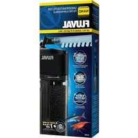
FX6 - Water filter Fluval - Free user manual and instructions
Find the device manual for free FX6 Fluval in PDF.

| Product type | External filter for freshwater or marine aquarium |
| Brand | Fluval |
| Model | FX6 |
| Recommended aquarium capacity | Up to 1500 L (400 US gal) |
| Pump flow rate | 3500 L/h (925 US gal/h) |
| Effective filter flow rate | 2130 L/h (563 US gal/h) |
| Total filtration volume | 20 L (5.28 US gal) |
| Biological filtration volume | 5.9 L (1.5 US gal) |
| Mechanical filtration surface area (foam) | 2100 cm² (325.5 in²) |
| Maximum head height | 3.3 m (10.8 ft) |
| Power consumption | 43 W (120 V/60 Hz) or 41 W (230-240 V/50 Hz) |
| Supplied hose length | 4 m (13.1 ft) |
| Maximum inlet hose length | 2 m (6.5 ft) |
| Priming | Automatic electronic |
| Number of filter baskets | 3 |
| Included filter media | Foam blocks (6), Bio-Foam (2), BioMax cylinders, carbon cartridge (1), filter bags (2) |
| Valve system | AquaStop with closure indicator |
| Maintenance | Monthly, quarterly, semi-annual and annual cleaning per chart |
| Warranty | 3 years |
| Usage | Indoor use only, non-submersible, max water temperature 35°C |
| Spare parts available | Yes, many references (e.g., A20201 for motor, A20210 for O-ring) |
Frequently Asked Questions - FX6 Fluval
User questions about FX6 Fluval
0 question about this device. Answer the ones you know or ask your own.
Ask a new question about this device
Download the instructions for your Water filter in PDF format for free! Find your manual FX6 - Fluval and take your electronic device back in hand. On this page are published all the documents necessary for the use of your device. FX6 by Fluval.
USER MANUAL FX6 Fluval
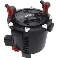
natural_image
Three black FX4 and FX6 power plant enclosures with red connectors, displayed against a blue abstract background (no text or symbols on the devices themselves)
TABLE OF CONTENTS
Parts Listing/ Replacement Parts ....EN-5
Safeguard Instructions....EN-6
Installation and Use ....EN-7
Specifications......EN-12
Maintenance....EN-13
Maintenance Frequency......EN-13
Warranty and Customer Service....EN-18

TABLE DES MATIÈRES
Z
FLUVAL FX6
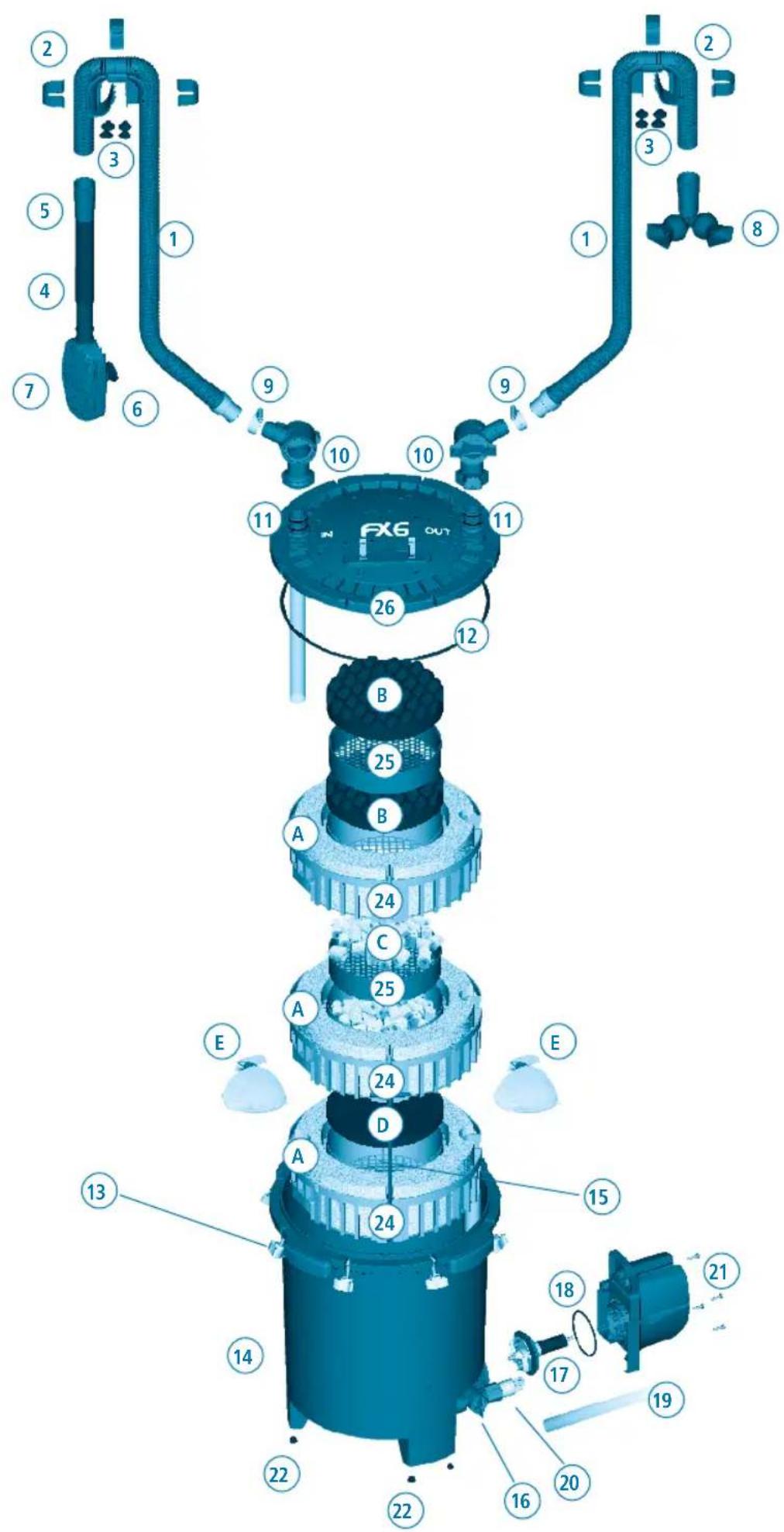
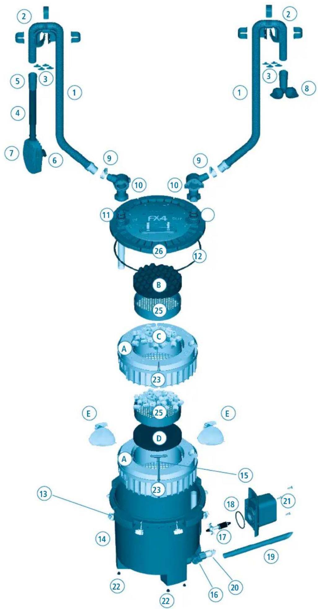
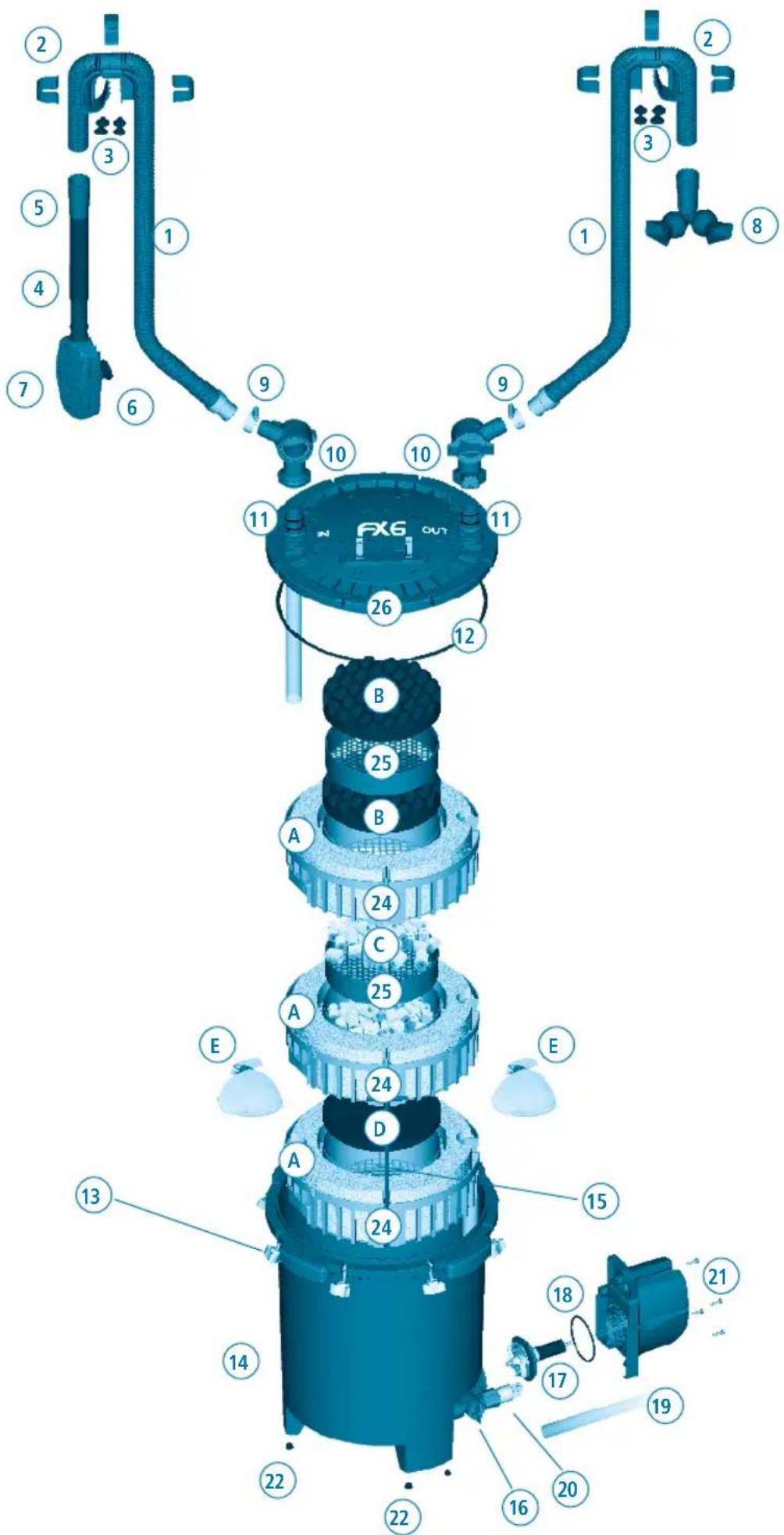
| Part Description Quantity | |
| 1 Ribbed Hosing 1 | |
| 2 Rim connector (1) & Clips (3) 2 | |
| 3 Rim Connector Suction Cups 8 | |
| 4 Intake Stem 1 | |
| 5 Rubber Connector 2 | |
| 6 Strainer Suction Cup 2 | |
| 7 Strainer 1 | |
| 8 Output Assembly (Nozzle) 1 | |
| 9 Metal Clamp (For hosing) 2 | |
| 10 Aqua Stop Valves 2 | |
| 11 Top cover click-fit O-ring | 4 |
| 12 O-Ring (Filter lid) | 1 |
| 13 Lid Fasteners | 8 |
| 14 Filter Canister | 1 |
| 15 T-Bar Handles | 2 |
| 16 Utility Valve | 1 |
| 17 Magnetic Impeller Assembly | 1 |
| 18 Motor Seal Ring | 1 |
| 19 Utility Valve Hosing | 1 |
| 20 Drain Cap | 1 |
| 21 Pump Unit (Motor) & Power Cord | 1 |
| 22 Rubber Feet | 6 |
| 23 Media baskets- FX4 | 2 |
| 24 Media baskets- FX6 | 3 |
| 25 12 Media basket | 2 |
| 26 Filter Lid | 1 |
| FX4 Item Number | FX6 Item Number | Quantity Spare Parts |
| A20236 | A20236 | 1 |
| A20230 | A20230 | 1 |
| A20232 | A20232 | 4 |
| A20225 | A20225 | 1 |
| A20228 | A20228 | 2 |
| A15041 | A15041 | 4 |
| A20221 | A20221 | 1 |
| A20227 | A20226 | 1 |
| A20234 | A20234 | 2 |
| A20216 | A20216 | 1 |
| A20212 | A20212 | 2 |
| A20210 | A20210 | 1 |
| A20215 | A20215 | 1 |
| N/A | N/A | |
| A20242 | A20241 | 1 |
| A20219 | A20219 | 1 |
| A20208 | A20206 | 1 |
| A20211 | A20207 | 1 |
| A20237 | A20237 | 1 |
| N/A | N/A | |
| A20202 | A20201 | 1 |
| A20121 | A20121 | 4 |
| A20239 | N/A | 1 |
| N/A | A20239 | 1 |
| A20243 | A20243 | 1 |
| N/A | N/A |
| Part | Description | FX4 Quantity | FX6 Quantity | FX4 Item Number | FX6 Item Number | Quantity Spare Parts |
| A | Foam | 4 | 6 | A228 | A228 | 3 |
| B | Bio Foam | 1 | 2 | A239 | A239 | 2 |
| C | Ceramic Rings (BioMax) | 2 | 2 | A1456 | A1456 | 1 |
| D | Carbon Pad | 1 | 1 | A249 | A249 | 2 |
| E | Media Bags | 2 | 2 | A1428 | A1428 | 2 |
WARNING - To guard against injury, basic safety precautions should be observed including the following:
1 READ & FOLLOW ALL SAFETY INSTRUCTIONS and all the important notices on the appliance before using. Failure to do so may result in the loss of fish life and/or damage to the appliance.
2. DANGER – To avoid possible electric shock, special care should be taken since water is employed in the use of aquarium equipment. For each of the following situations, do not attempt repairs yourself, return the appliance to an authorized service facility for service or discard the appliance.
A. If the appliance falls into the water, DON'T reach for it! First unplug it and then retrieve it. If electrical components of the appliance get wet, unplug the appliance immediately.
B. If the appliance shows any sign of abnormal water leakage or if RCD (or GFCI – Ground Fault Current Interrupter) switches off disconnect the power supply cord from the mains and remove pump from water.
C. Carefully examine the appliance after installation. It should not be plugged if there is water on parts not intended to be wet.
D. Do not operate any appliance if it has a damaged cord or plug, or if it is malfunctioning or it is dropped or damaged in any manner. The power cord of this appliance cannot be replaced. If the cord is damaged, the appliance should be discarded. Never cut the cord.
E. To avoid the possibility of the appliance plug or receptacle getting wet, position the appliance to one side of a wall mounted receptacle. To prevent water from dripping onto the receptacle or plug, a "drip loop" (see photo) should be arranged by the
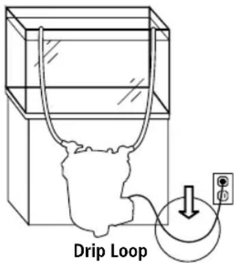
user in the cord connecting appliance to a receptacle. The "drip loop" is that part of the cord below the level of the receptacle or the connector, to prevent water travelling along the cord and coming in contact with the receptacle. If the plug or receptacle does get wet, DON'T unplug the cord. Disconnect the fuse or circuit breaker that supplies power to the appliance. Then unplug and examine for presence of water in receptacle.
- WARNING – Close supervision is necessary when any appliance is used by or near children. This appliance can be used by children ages 8 years and above and persons with reduced physical, sensory or mental capabilities or lack of experience and knowledge if they have been given supervision or instruction concerning use of the appliance in a safe way and understand the hazards involved. Children shall not play with the appliance. Cleaning and user maintenance shall not be made by children without supervision.
- To avoid injury, do not touch moving parts or hot parts.
- CAUTION – Always unplug or disconnect all appliances in the aquarium from electricity supply before placing hands in water, before putting on or taking off parts and while the equipment is being installed, maintained or handled. Grasp the plug and pull to disconnect. Never yank cord to pull plug from outlet. Always unplug an appliance from an outlet when not in use.
- This appliance is not a submersible aquarium filter-pump. It is intended for use in ornamental household aquariums. It may be used with fresh or salt water. Maximum water temperature 35^ C. Do not use this appliance for other than intended use (ie: DO NOT use in swimming pools, bathrooms, ect.). The use of attachments not recommended or sold by the appliance manufacturer may cause an unsafe condition and will invalidate your warranty.
- This is a HOUSEHOLD APPLIANCE INTENDED FOR DOMESTIC USE and it is suitable for INDOOR use only. Do not install or store this appliance where it will be exposed to the weather or temperatures below freezing.
- Make sure that this appliance is securely installed before operating it and that the electrical connection is in accordance with the data on the rating label. Do not allow filter pump to run dry.
- If an extension cord is necessary, a cord with proper rating should be used. A cord rated for less amperes or watts than the appliance rating may overheat. Care should be taken to arrange the cord so that it will not be tripped over or pulled. The connection should be carried out by a qualified electrical installer.
10. SAVE THESE INSTRUCTIONS for future reference.
INSTALLATION AND USE
1. Before beginning
- For best results, top off water in aquarium before beginning setup.
- Allow 30-45 minutes for setup and installation.
- Tools required: Phillips screwdriver and utility knife.
- Read all instructions.
DO NOT PLUG IN FILTER UNTIL SETUP IS COMPLETE AND UNIT IS FILLED WITH WATER.
2. Unpack and identify all parts
Use the diagram at the beginning of the manual.
3. Prepare the aquarium
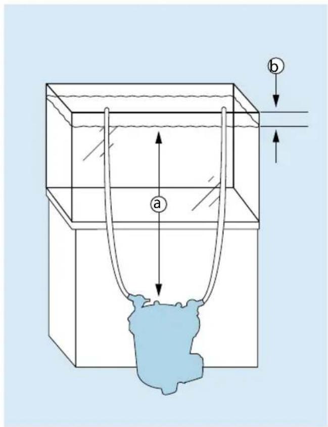
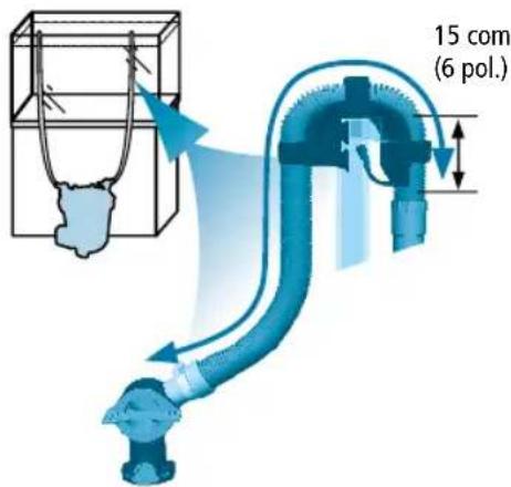
- Decide on filter placement. Remember, this is a gravity-fed system. For it to work properly, all of the Installation Requirements below must be adhered to.
| FX4 FX6 | ||
| a min. | 20 cm to 150 cm min. | 20 cm to 150 cm |
| b max. | 20 cm max. | 20 cm |
IMPORTANT:
- NEVER install the filter above the water level.
- The hosing supplied with the unit is 13.1 ft (4m) long. If longer hosing is required, intake hosing must not exceed 6.5 ft. (2m) and the total length of intake and outlet hosing combined must not exceed 16.4 ft. (5m).
- Hosing must follow a straight path from the filter to the aquarium rim, with no slack and no loops.
- For best performance, the filter should be completely beneath the aquarium (as in figure shown).
- Position utility valve so that you will be able to attach the supplied hosing without moving the unit.
INSTALLATION AND USE
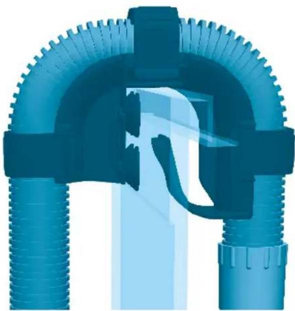
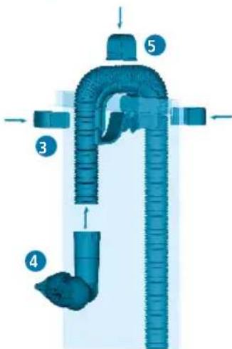
- Place the two rim connectors over the back top edge of the aquarium. Place one just above the spot where you want to place the intake tube; place the other just over the spot where you want to position the output nozzle. Be sure that the long end of the bracket is on the inside of the aquarium.
The rubber rings on the connectors are designed to help them adhere to tank glass better. If the aquarium walls are thinner than 5/8 in. (1.58 cm) replace the rubber ring with the four smaller suction cups provided.
IMPORTANT: Be sure to position the intake tube away from any air source—an air stone, an aeration device, protein skimmer or the output valve. Air entering the intake strainer will diminish filter efficiency.
natural_image
3D rendered diagram of a mechanical pipe assembly with flanged ends and central valve (no text or symbols)Alternate Configurations
natural_image
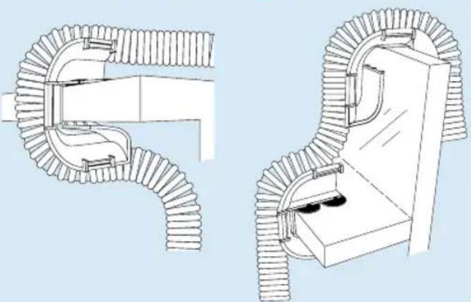
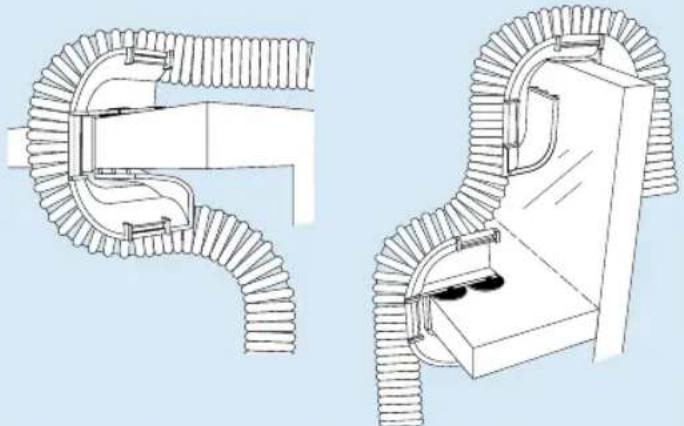
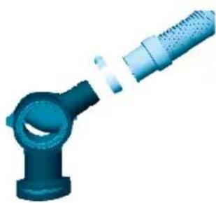
Technical line drawing of two mechanical pipe fittings with ribbed ends and a door mechanism (no text or symbols)Note: A dropped ledge rim requires purchase of an extra rim connector. (See "Replacement Parts" for ordering information.)
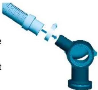
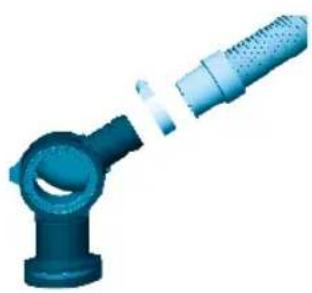
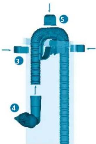
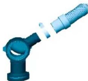
1. Prepare intake connections
- Connect the hosing to one of the two valves (marked "IN"):
A. Loosen one of the metal clamps, and slide it onto one end of the hosing (the rubber part).
B. Push the end of the hosing onto the valve; push it all the way, as far as it will go.
C. Position the metal clamp over the rubber connector, and tighten.
- Measure and cut the hosing. You will need a length of hosing that reaches comfortably from inside the aquarium to the filter canister.
IMPORTANT: Hosing should follow a straight path from the filter to the aquarium rim, with no slack and no loops. If the hosing is too long, the filter will not work efficiently (the maximum length of the hosing is 6.5 ft / 2m).
D. Place the valve end of the hosing at the approximate spot where it will be positioned on the filter lid (once the filter is installed).
E. Stretch out the hosing so it rests over the "intake" rim bracket.
F. At a spot at least 6 in. (15cm) beyond the aquarium rim, use a utility knife to cut the hosing. Do not cut it too short. Remember, you can always cut it shorter during final installation, if necessary.
natural_image
3D illustration of a blue mechanical joint or connector with a pin inserted, no text or symbols present
INSTALLATION AND USE
- Push the cut end of this "intake" hosing into the rubber connector on the intake tube. Push the hosing in by at least 1 in. (2.5cm) without twisting it.
- Place the intake strainer in the tank, making sure it is at least 3 in. (7.5 cm) from the bottom. Adjust the intake tube for the best extension for your aquarium, respecting the 3 in. (7.5 cm) from the bottom rule. Once the intake strainer is properly positioned, lock it in place by pressing the suction cups against the glass.
- Fasten the intake strainer's hosing onto the rim connector using the three rim connector clips.
5. Prepare output connections
- Connect the hosing to the second valve (Just as for the intake hos-ing):
A. Loosen the second metal clamp, and slide it onto the factory-finished end of the hosing (not the cut end).
B. Push the end of the hosing onto the valve; push it all the way, as far as it will go.
C. Position the metal clamp over the rubber connector, and tighten.
- Measure and cut the hosing. Again, you will need a length of hosing that reaches comfortably from inside the aquarium to the filter canister.
IMPORTANT: Hosing should follow a straight path from the filter to the aquarium rim, with no slack and no loops. If the hose is too long, the filter will not work efficiently.
D. Place the valve end of the hosing at the approximate spot where it will be positioned on the filter lid (once the filter is installed).
E. Stretch out the hosing so it rests over the "output" rim bracket.
F. At a spot at least 6 in. (15cm) beyond the aquarium rim, use a utility knife to cut the hosing. Do not cut it too short. Remember, you can always cut it shorter during final installation, if necessary - Push the cut end of this "output" hosing into the rubber connector of the output nozzle. Push the hosing in by at least 1 in. (2.5cm) without twisting it.
- Place the nozzle in the tank about 1 in. (2.5cm) below the water line.
- Fasten the hosing to the "output" bracket using the three rim connector clips.
Z

natural_image
Blue industrial pipe fitting with a coiled hose, shown in 3D rendering (no text or symbols)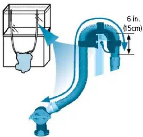

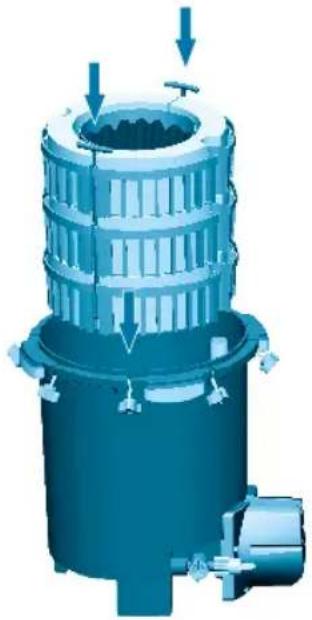
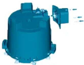
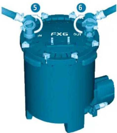
6. Prepare the filter
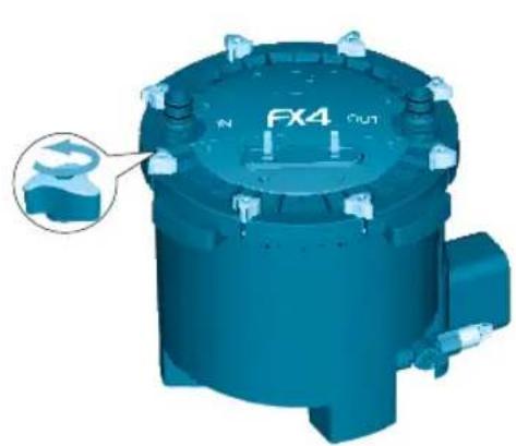
- Loosen and disengage the eight lid fasteners.
- Remove the filter lid and set it aside. Be careful not to damage the inlet stem connected to the lid.
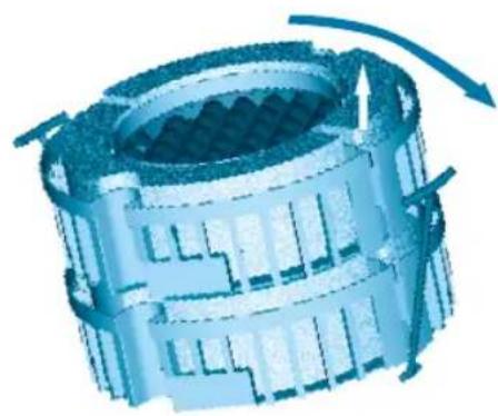
- Using the red T-handles, lift the media baskets from the filter canister. The T-handles will fall outward so the baskets can be handled separately. The images below are referred to FX4; FX6 has an additional basket.
natural_image
3D rendering of a blue industrial component with mounting holes and a labeled part 'FX4 OUT' (no readable text beyond labels)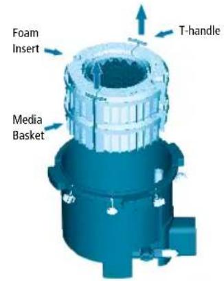
natural_image
3D rendering of a mechanical gear assembly with rotational arrows indicating motion (no text or symbols)- Rinse baskets, media trays and media materials under running tap water to remove any dust, and place media back in their original position. Or, if you prefer, select other media of your own choosing.
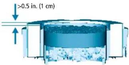
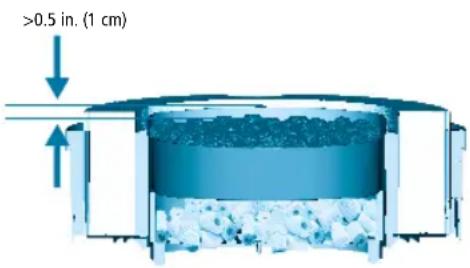
IMPORTANT: To prevent particles from entering the impeller chamber, blocking and/or damaging the impeller, all loose granule filter material (Carbon, Zeo-Carb, Ammonia Remover, Peat Granules, etc.) must be placed in a filter media bag. Please use the bags at the bottom basket for these filtering media. NEVER overfill baskets. Leave at least 0.5 in. (1cm) of free space from the top of the baskets to the media, so the baskets will fit together properly. If the red tray is present, the media at the bottom of the basket must not exceed the height of the tray supports in the basket.
- Make certain that each kind of media is positioned at the same level it was packaged in, unless you are deliberately choosing a different filtration plan than the recommended setup.
- Stack the baskets, carefully aligning them, so that all shapes match. Re-insert the T-handles into their vertical slots, and replace the baskets in the filter canister. The foam in the upper basket should be just about even with the top edge of the canister (the output tube, which is affixed to the inside of the canister, will be protruding slightly).
- Move the filter canister to its final position.
- Be certain the utility valve is in the vertical (closed) position.
- Pour at least 1.6 gallons (6 liters) for FX4 and 2 gallons (8 liters) for FX6 of water into the filter canister.
IMPORTANT: Correct water volume is necessary for system priming.
- Place the filter lid back on the canister. Check to make sure the filter lid seal ring is present and installed properly on the canister lid. There is only one orientation possible. Gently press the lid down until the output tube is firmly seated in the OUT connection on the filter lid.
IMPORTANT: If the inlet tube attached to the canister lid has slipped out of its seat, be sure to fully re-insert it under the IN connection of the lid.
- Replace and hand-tighten the eight lid fasteners. The lid is properly closed when it is in direct contact with the canister. DO NOT USE ANY TOOLS, AS DOING SO MAY DAMAGE THE UNIT.
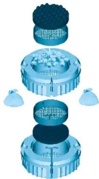
natural_image
Exploded view diagram of a mechanical assembly with no visible text or symbolsFX4 Shown
7. Install the Filter
- Once the filter unit is in its final position, make sure that the aquarium has the appropriate amount of water.
Z
IMPORTANT: Before proceeding, check the Installation Requirements at section #3 of "Installation and Use" chapter.
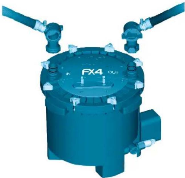
-
Grasp the intake valve (which is at the end of the hosing attached to the intake tube); slide it onto the IN connection on the filter lid, and press until it clicks into place.
-
Grasp the output valve (which is at the end of the hosing attached to the output nozzle); slide it onto the OUT connection on the filter lid, and press until it clicks into place.
-
Be certain both valves are locked in place before proceeding.
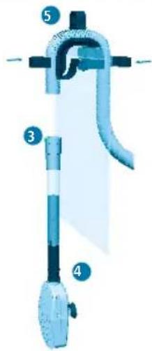
8. Install the Utility Valve hosing
The utility valve at the base of the unit and its hosing allow to:
- Discharge the water inside the filter to make it lighter for moving it.
- Change aquarium water: empty and refill.
- Use the FX gravel cleaner kit (sold separately).
To install the utility hosing proceed as follows:
- Be certain the utility valve is in the closed (vertical) position; turn the lock nut clockwise to loosen it, then remove the rubber cap.
- Attach one end of the supplied hose to the utility valve. Turn lock nut counterclockwise while you are pushing the hose in the valve direction.
- Attach the other end of the hose to the clips on the lid.
natural_image
3D rendering of a blue industrial mechanical component with no visible text or symbols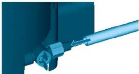
natural_image
Close-up of a blue mechanical component with a metallic rod inserted (no visible text or symbols)WARNING: It is important to leave the valve in the OFF position when not in use. An open valve will result in an immediate water spill.
9. Start the filter
- Check your installation.
Before turning the filter on, be sure that:
A. The utility valve is in the closed (vertical) position.
B. All top lid fasteners are well tightened.
C. The intake strainer is fully submersed in water.
D. There are at least 1.6 gallons (6 liters) for FX4 and 2 gallons (8 liters) for FX6 of water in the canister.
INSTALLATION AND USE
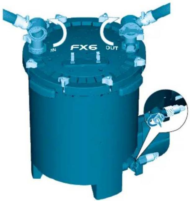
VERY IMPORTANT: You need to know that as soon as the unit is plugged in, it will start, and will immediately go through its automatic priming sequence.
- Open the IN & OUT valve levers placing them in the vertical position.
- Plug the unit into an electrical outlet.
The electronic automatic priming sequence will begin. This is what will happen:
E. The pump will run for 1 minute to fill the filter canister with aquarium water.
F. The pump will stop for 2 minutes to evacuate air from the filter canister.
G. The pump will start again; it will remain on and will run continuously until it is unplugged.
This sequence will repeat itself every time the unit is unplugged and plugged back in.
Every 12 hours the pump will stop for 1 minute to evacuate any air that may have become trapped inside the unit.
natural_image
3D rendering of a blue industrial container with labeled ports (FX6, OUT) and internal tubing, showing no readable text beyond labels.| FX4 FX6 | ||||
| Aquarium Capacity: 250 gallons 1,000 liters 400 gallons 1,500 liters | ||||
| Pump Output: 700 g/h 2650 l/h 925 g/h 3,500 l/h | ||||
| Mechanical Area (Foam) | 217 in.^2 | 1,400 cm^2 | 325.5 in.^2 | 2,100 cm^2 |
| Biological Volume: | 1 gallon | 3.9 l | 1.5 gallons | 5.9 l |
| Filtration Volume: | 3.7 gallons | 14 l | 5.28 gallons | 20 l |
| Filter Circulation*: | 450 g/h | 1,700 l/h | 563 g/h | 2,130 l/h |
| Head Height (max.): | 6.9ft | 2.1 m | 10.8ft | 3.3 m |
| Wattages 120V/60Hz: | 30W | 43W | ||
| Wattages 230-240V/50Hz: | 30W | 41W | ||
| *Note: Flow rates were measured with intake and output hoses of the same length and without media. | ||||
CAUTION: Always unplug any appliances from an outlet when not in use, before putting on or taking off parts, and before cleaning. Never yank cord to pull plug from outlet. Grasp the plug and pull to disconnect.
IMPORTANT
To ensure optimal and proper functioning of your Fluval FX External Filter, regular maintenance is required. Failure to do so may result in the failure of the filter and will invalidate your warranty. Additionally, regular cleaning and maintenance will greatly reduce or completely prevent faults and reduction in performance. Please refer to the maintenance schedule below.
FX filters allow you to make an easy and efficient maintenance of your aquarium.
Gravel cleaning
For this operation we recommend you to use the FX gravel cleaning kit. Please refer to the instructions included with your FX Gravel Cleaning Kit. (Sold Separately)
Water changing
For this operation please refer to the plastic instruction sheet included with your filter.
* IMPORTANT: During these operations, air may get trapped inside the canister that can shake the dirt onto the bottom. If you have not done regular maintenance of the inside of the canister as recommended by the maintenance frequency chart, some particles may get flushed back into the aquarium.
CAUTION: Always unplug any appliances from an outlet when not in use, before putting on or taking off parts, and before cleaning. Never yank cord to pull plug from outlet. Grasp the plug and pull to disconnect.
FILTER MAINTENANCE
Prior to periodic maintenance the canister must be drained.
1. Drain the filter
- Turn the IN and OUT valves in sequence to the closed (horizontal) position.
- Unplug the pump from the electrical power supply.
- Remove the utility hose from the clips on the lid and position its end in an appropriate basin or discharge drain.
- Turn the utility valve to the open (horizontal) position by turning it counterclockwise. Then disconnect the OUT valve.
- Water will immediately begin to drain from the canister. Since this is a gravity fed method, water will stop draining once the water level in the canister and drain bucket equalize. Once this happens simply close the valve and empty the bucket. Repeat the draining process until enough water is removed to make the canister light enough to carry to your work area.
2. Disassemble the unit
- Move the filter to an appropriate area convenient for maintenance.
- Loosen and remove the eight lid fasteners; remove the filter lid and set aside. Be careful not to damage the inlet stem connected to the lid.
- Using the red T-handles, lift the media baskets from the filter canister; let the T-handles fall out of their slots, and separate the baskets.
3. Cleaning or replacing media
-
Remove all foam inserts from the media baskets and trays, rinse using aquarium or de-chlorinated tap water, or replace with new foam, as required.
-
Rinse biological media with aquarium water, or replace, as required.
-
Replace chemical media, as needed. Chemical media cannot be cleaned.
-
Empty and rinse the filter canister. NEVER use soap or detergents when cleaning the canister or rinsing the baskets and trays, as remaining traces of cleaning products may damage sensitive fish tissue.
-
NEVER overfill baskets. Leave at least 0.5 in. (1cm) of free space from the top of the baskets to the media, so the baskets will fit together properly. If the red tray is present, the media at the bottom of the basket must not exceed the height of the tray supports in the basket.
CAUTION: Always unplug any appliances from an outlet when not in use, before putting on or taking off parts, and before cleaning. Never yank cord to pull plug from outlet. Grasp the plug and pull to disconnect.
N
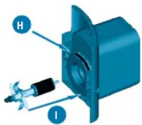
4. Pump care
FX4 IMPELLER MAINTENANCE
The impeller well has an effective self-cleaning feature. However it is recommended that you remove the motor and inspect the impeller as part of your routine maintenance. Keeping the impeller clean lengthens its life and the life of the motor. Prior to performing pump care the FX4 Filter must be completely emptied of water, media baskets, and media.
1. To remove the pump unit:
A. Place the filter unit upside down on a secure work area so that the pump screws and screw seats are visible. Remember that the output tube protrudes slightly from the top rim of the canister. Be sure not to bend or damage the tube while it is upside down.
B. Unscrew the 3 fixing screws using a Phillips screwdriver (cross headed). Screws are located around the motor housing.
C. Remove the impeller assembly by grasping the fan and drawing it gently from the well.
NOTE: There are 4 parts to the impeller:
D. Impeller shaft. The impeller shaft is held on both sides of the impeller well by two rubber bushings. The shaft can be easily extracted by hand with care.
IMPORTANT: The shaft is made from ceramic, which is resistant to wear and tear in use, but is fragile. Handle carefully during maintenance.
E. Front rubber bushing. If it remains in the red part of the canister, it's necessary to remove it keeping attention to not damage it.
F. Rear rubber bushing. If the rubber bushing remains in its place, it's not necessary to remove it.
G. Impeller assembly (Magnet + impeller fan)
2. Clean the impeller and the impeller well thoroughly by rinsing with clear running water.
3. Re-assemble all pump components with care:
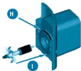
H. Replace seal ring if necessary: Remove it from the loophole. Please refer to the "maintenance frequency chart". For this operation do not use any tools because there is a risk of damage to the O-ring.
- Re-assemble all parts in the following order: Rear rubber bushing at the bottom of the well (if removed), ceramic shaft (pushing it until it stops); subsequently the impeller assembly and at the end the front rubber bushing at the top of the ceramic shaft. The shaft can be easily reinserted by hand; however, pay close attention and be certain the rubber bushing does not become unseated.
4. Replace the pump unit with care into the canister and affix it using the 3 fixing screws with a Phillips screwdriver (cross headed). While re-assembling the pump, the 3 fixing screws should be gently screwed in until pump motor cover and canister are securely attached.
NOTE: Do not over tighten housing to canister.
IMPORTANT: Be sure that the seal ring does not slip out of its seat.
natural_image
3D rendering of a blue industrial component with labeled part B (no text or symbols on the object itself)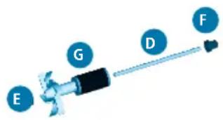

natural_image
3D rendered model of a blue cylindrical mechanical component with a separate outlet and directional arrows (no text or symbols)CAUTION: Always unplug any appliances from an outlet when not in use, before putting on or taking off parts, and before cleaning. Never yank cord to pull plug from outlet. Grasp the plug and pull to disconnect.
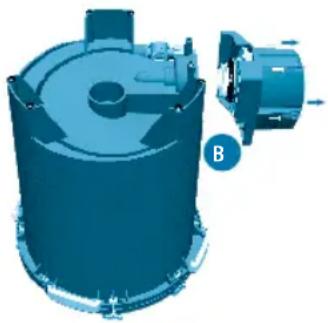
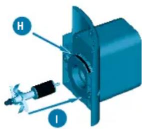
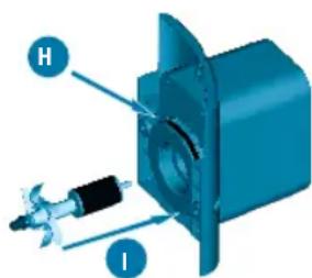
FX6 IMPELLER MAINTENANCE
The impeller well has an effective self-cleaning feature. However it is recommended that you remove the motor and inspect the impeller as part of your routine maintenance. Keeping the impeller clean lengthens its life and the life of the motor. Prior to performing pump care the FX6 Filter must be completely emptied of water, media baskets, and media.
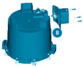
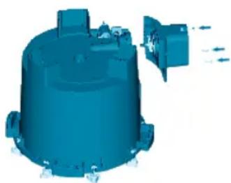
- To remove the pump unit:
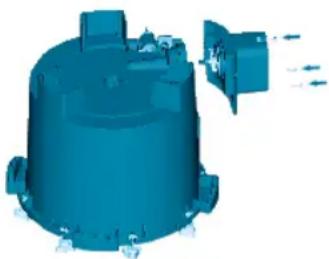
A. Place the filter unit upside down on a secure work area so that the pump screws and screw seats are visible. Remember that the output tube protrudes slightly from the top rim of the canister. Be sure not to bend or damage the tube while it is upside down.
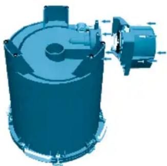
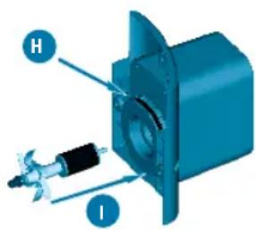
B. Unscrew the 4 fixing screws using a Phillips screwdriver (cross headed). Screws are located around the motor housing.
C. Remove the impeller assembly by grasping its flange (black disc).
-
Clean the impeller and the impeller well thoroughly by rinsing with clear running water.
-
Re-assemble all pump components with care:
D. Align the two arrows on the impeller assembly. Before inserting the impeller, gently press the magnet against the flange to be sure that the flange bushing is fully in its seat.
E. Replace seal ring if necessary. Please refer to the Maintenance Frequency Chart.
- Re-attach the pump unit to the canister using the 4 fixing screws with a Phillips screwdriver (cross headed). While re-assembling the pump, the 4 fixing screws should be gently screwed until pump motor cover and canister are securely attached. Note: Do not over tighten housing to canister.
IMPORTANT: Be sure that impeller bearing (bushing and O-Ring) is correctly placed at the bottom of the impeller well. Though the bushing is made of very resistant material, it is prone to wearing in certain conditions. For this reason, it is recommended that you replace it whenever the impeller unit is replaced. Follow the instructions provided with the replacement parts package. For any details, please refer to the Maintenance Frequency Chart.
IMPORTANT: Be sure that the seal ring does not slip between the impeller flange and the motor and that the impeller bearing (bushing and O-Ring) is correctly placed at the bottom of the impeller well.
natural_image
3D rendering of a blue industrial cylindrical device with internal components and a separate motor assembly (no text or symbols visible)
natural_image
3D illustration of a mechanical device with directional arrows and a labeled component 'C' (no text or symbols beyond label)

natural_image
3D rendering of a blue industrial cylindrical device with internal components and mounting bracket (no text or symbols visible)MAINTENANCE
CAUTION: Always unplug any appliances from an outlet when not in use, before putting on or taking off parts, and before cleaning. Never yank cord to pull plug from outlet. Grasp the plug and pull to disconnect.
5. Re-assemble the unit
-
Stack the baskets, aligning them so all shapes match. Re-insert the T-handles into their vertical slots, and lower the baskets into the filter canister. Foam in upper basket should be just about even with the top edge of the canister.
-
Replace filter lid.
A. Inspect the lid gasket for wear and tear.
B. Place filter lid back on canister. There is only one orientation possible. Gently press the lid down until the output tube, affixed to the inside of the filter canister, is firmly seated in the output (OUT) valve lid opening.
IMPORTANT: If the inlet tube attached to the canister lid has slipped out of its seat, be sure to fully re-insert it under the IN connection of the lid.
-
Replace and hand-tighten the eight lid fasteners. The lid is properly closed when it is in direct contact with the canister. DO NOT USE ANY TOOLS, AS DOING SO MAY DAMAGE THE UNIT.
-
Place the IN and OUT valves back on the lid connectors and press firmly until they click into place. Be sure the IN valve is connected to the hose attached to the intake strainer, and the OUT valve is connected to the hose attached to the output nozzle.
-
Open the IN valve (turn to vertical position).
-
With the IN valve already open, open the OUT valve. Do not change this sequence, or the canister will not refill properly. If the canister is no longer primed, see "Start the Filter".
-
You will be able to hear water filling the canister. Meanwhile, air will be forced through the output nozzle, causing bubbling and agitation in the aquarium. Once the bubbling in the aquarium stops, plug the power cord back in. The pump will resume its normal stop/start sequence as described in "Start the Filter."
Any other servicing should be performed by an authorized service representative.
natural_image
3D rendering of a mechanical device with internal components and mounting features (no visible text or symbols)
QUESTIONS? If you have a problem or question about the operation of this product, please let us try to help you before you return the product to your dealer. Most problems can be handled promptly with a phone call. Or, if you prefer, you can contact us on our web site at www.fluvalaquatics.com. When you call (or write), please have all relevant information, such as model number and/or part numbers available.
USA
CALL US ON OUR TOLL-FREE NUMBER: 1-800-724-2436 between 8:30 a.m. and 4:00 p.m. Eastern Standard Time. Ask for Customer Service.
CANADA
CALL US ON OUR TOLL-FREE NUMBER: 1-800-554-2436 between 9:00 a.m. and 4:00 p.m. Eastern Standard Time. Ask for Customer Service.
UK
Helpline Number 01977 521015. Between 9:00 AM and 5:00 PM, Monday to Thursday and 9:00 AM and 4:00 PM on Friday (excluding Bank Holidays). Ask for Customer Service.
FOR AUTHORIZED GUARANTEE REPAIR SERVICE: Return with dated receipt and \$4.00 for postage and handling to:
Consumer Repairs Rolf C. Hagen (USA) Corp 305 Forbes Blvd Mansfield, MA 02048
FOR AUTHORIZED GUARANTEE REPAIR SERVICE: Return with dated receipt and \$4.00 for postage and handling to: Rolf C. Hagen Inc. Service and Repair 20500 Trans Canada Hwy Baie d'Urfé, Québec H9X 0A2
FOR AUTHORISED WARANTY SERVICE please return (well packaged and by registered post) to the address below enclosing dated receipt and reason for return. Customer Service Department Rolf C. Hagen (UK) Ltd California Drive, Whitwood Ind Est., Castleford West Yorkshire WF10 5QH
RECYCLING: This symbol bears the selective sorting symbol for waste electrical and electronic equipment (WEEE). This means that this product must be handled pursuant to European Directive 2012/19/EU in order to be recycled or dismantled to minimize its impact on the environment. Check with your local Environmental Agency for possible disposal instructions or take to an official council registered refuse collection point. Electronic products not included in the selective sorting process are potentially dangerous for the environment and human health due to the presence of hazardous substances.
Three Year Warranty
The Fluval FX4/FX6 Canister Filter is guaranteed against defects in material and workmanship under normal aquarium usage and service for 3 years from date of purchase. Non-replaceable and non-serviceable parts will be repaired or replaced at Hagen's discretion, free of charge, when the complete filter is returned with all components along with a valid proof of purchase and postage paid. This warranty does not apply to any filter that has been subject to misuse, negligence or tampering. It does not apply to filters which have been incorrectly assembled or unsuitably maintained or where installation and maintenance instructions have not been followed correctly. The warranty does not apply to wear and tear parts such as the impeller, impeller cover or motor seal. No liability is assumed with respect to loss or damage to livestock or personal property irrespective of the cause thereof. Before returning the filter under warranty terms, please ensure that all setup and maintenance instructions have been followed. If you are in doubt, please contact your local aquatic specialist retailer for further advice before returning the product. THIS DOES NOT AFFECT YOUR STATUTORY RIGHTS.
FLUVAL FX4
FR
FLUVAL FX6

PIÈCES DE L'APPAREIL/PIÈCES DE RECHANGE
natural_image
3D rendered diagram of a mechanical pipe fitting with flanged ends and a central component (no text or symbols)natural_image
Technical line drawing of two mechanical assembly configurations with coiled tubing (no text or symbols)natural_image
3D rendering of a blue mechanical joint or connector with a threaded shaft and pipe fitting (no text or symbols visible)
INSTALLATION ET UTILISATION

natural_image
3D illustration of a blue mechanical pipe fitting with a coiled cable, showing internal structure (no text or symbols)

INSTALLATION ET UTILISATION
natural_image
Exploded view diagram of a mechanical assembly with no visible text or symbolsnatural_image
3D rendering of a blue industrial machine component with no visible text or symbols on the body itself.FR
natural_image
Close-up of a mechanical component with a blue arrow indicating direction (no visible text or symbols)natural_image
3D rendering of a blue industrial cylindrical device with labeled ports (FX6, OUT) and internal tubing, showing no readable text beyond labels.natural_image
3D rendering of a blue industrial component with labeled part B (no text or symbols on the object itself)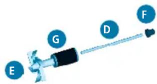
natural_image
3D rendered model of a blue cylindrical industrial component with a side-mounted fan or vent (no text or symbols visible)natural_image
3D rendering of a blue industrial cylindrical device with internal components and a separate motor assembly (no text or symbols visible)
natural_image
3D illustration of a mechanical device with directional arrows and a labeled component 'C' (no text or symbols beyond label)

natural_image
3D rendering of a blue industrial cylindrical device with internal components and mounting bracket (no text or symbols visible)ENTRETIEN
natural_image
3D rendering of a blue industrial machine with internal components and mounting ports (no visible text or symbols)

Boulevard Jean Monnet
F-77388 Combs-la-ville

FLUVAL FX6
natural_image
3D illustration of a mechanical pipe fitting with flanged ends and a central valve (no text or symbols)Alternative Konfigurationen
natural_image
Technical line drawing of two mechanical ventilation systems with coiled ducts and ventilation components (no text or symbols)natural_image
3D rendering of a blue mechanical joint or connector with no visible text or symbols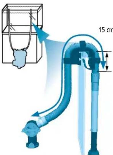

natural_image
3D illustration of a blue mechanical pipe fitting with a coiled cable, showing internal components (no text or symbols)
natural_image
3D rendering of a blue industrial machine with mounting holes and a labeled component (no readable text or symbols beyond branding)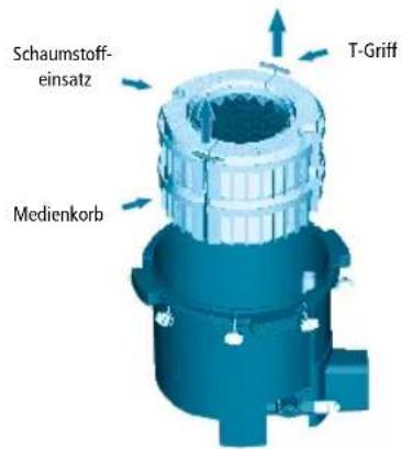
natural_image
3D mechanical component diagram showing rotational flow with arrows indicating direction (no text or symbols)natural_image
Exploded view diagram of a mechanical assembly with multiple components and no visible text or symbolsAbb. FX4
natural_image
3D rendering of a blue industrial mechanical component with inlet/outlet ports and no visible text or symbolsDE
natural_image
Close-up of a mechanical component with a blue arrow indicating direction (no visible text or symbols)natural_image
3D rendering of a blue industrial cylindrical device with labeled ports (FX6, OUT) and internal tubing, showing no readable text beyond branding.FLUVAL FX SPEZIFIKATIONEN
natural_image
3D rendering of a blue industrial vessel with a labeled component 'B' and directional arrows (no text or symbols on the vessel itself)DE


natural_image
3D rendered model of a blue cylindrical mechanical component with mounting flanges and a protruding shaft (no text or symbols visible)natural_image
3D rendering of a blue industrial cylindrical device with internal components and a separate motor assembly (no text or symbols visible)
natural_image
3D illustration of a mechanical device with directional arrows and a labeled component 'C' (no text or symbols beyond label)
natural_image
3D rendering of a blue industrial cylindrical device with internal components and mounting bracket (no text or symbols visible)WARTUNG
natural_image
3D rendering of a blue industrial machine with internal components and mounting features (no text or symbols visible)


FLUVAL FX6

INSTALACIÓN Y USO
natural_image
3D illustration of a mechanical pipe fitting with meshed ends and a central valve (no text or symbols)natural_image
Technical line drawing of two mechanical pipe fittings with ribbed ends and a central opening (no text or symbols)natural_image
3D illustration of a blue mechanical component with a threaded shaft and connector, connected to a pipe fitting (no text or symbols)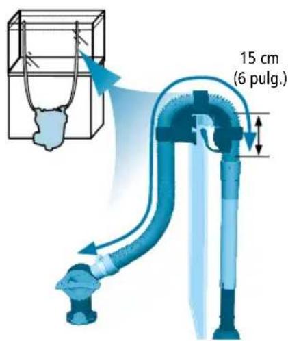
INSTALACIÓN Y USO

natural_image
3D rendering of a blue mechanical pipe fitting with a threaded end (no text or symbols)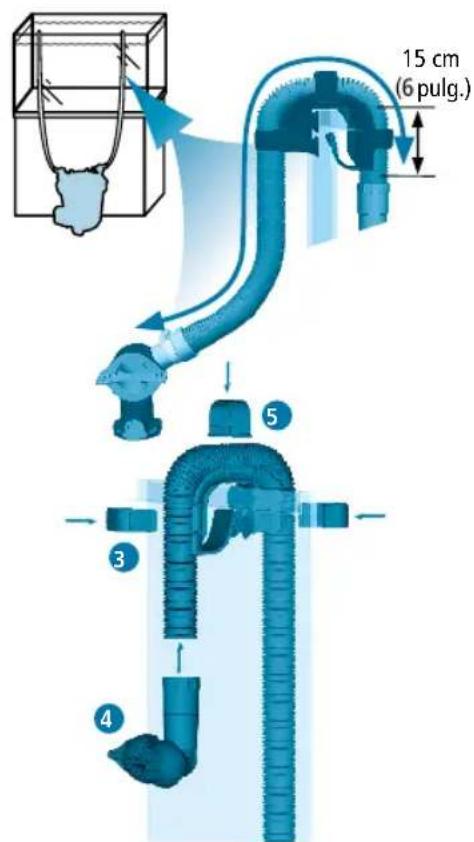
INSTALACIÓN Y USO
natural_image
3D rendering of a blue industrial component with mounting holes and a labeled part (no readable text or symbols beyond branding)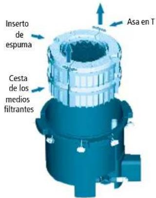
natural_image
3D mechanical component diagram showing rotational flow with arrows indicating direction (no text or symbols)natural_image
3D illustration of a multi-tiered mechanical component with textured surfaces and small bags (no text or symbols)Demostración de FX4
INSTALACIÓN Y USO
natural_image
3D rendering of a blue industrial component with inlet and outlet ports, no visible text or symbolsnatural_image
Close-up of a mechanical component with a blue handle and arrow indicator (no visible text or symbols)natural_image
3D rendering of a blue industrial cylindrical device with labeled ports (FX6, OUT) and internal tubing, showing no readable text or symbols beyond branding.natural_image
3D rendering of a blue industrial component with mounting flanges and a labeled section B (no text or symbols on the object itself)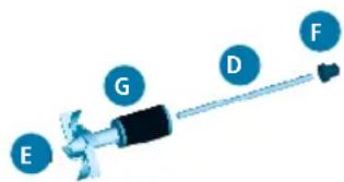

natural_image
3D rendered model of a blue cylindrical industrial component with mounting flanges and a protruding outlet (no text or symbols visible)natural_image
3D rendering of a blue industrial machine component with no visible text or symbolsnatural_image
3D illustration of a mechanical device with directional arrows and a labeled component 'C' (no text or symbols beyond label)
natural_image
3D rendering of a blue industrial cylindrical device with internal components and mounting bracket (no text or symbols visible)MANTENIMIENTO
natural_image
3D rendering of a blue industrial machine with internal components and mounting features (no visible text or symbols)


FLUVAL FX6

natural_image
3D rendered diagram of a mechanical pipe assembly with flanged ends and central valve (no text or symbols)Wisselende configuraties

natural_image
Technical line drawing of two mechanical pipe fittings with ribbed ends and a central support structure (no text or symbols)natural_image
3D rendering of a blue mechanical joint or connector with no visible text or symbols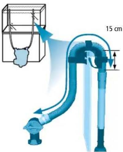
INSTALLATIE EN GEBRUIK
NL
natural_image
3D rendering of a blue mechanical pipe fitting with a textured end (no text or symbols)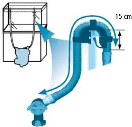
6. Maak de filter klaar
natural_image
3D mechanical component diagram showing internal structure with directional arrows (no text or symbols)natural_image
Exploded view diagram of a mechanical assembly showing layered components with no visible text or symbolsAfbeelding FX4
natural_image
3D rendering of a blue industrial component with inlet/outlet pipes and central branding (no readable text or symbols beyond branding)NL
8. Installeer de slang van de nutsklep
natural_image
Close-up of a mechanical component with a blue arrow indicating direction (no visible text or symbols)natural_image
Blue industrial engine cylinder with labeled ports (FX6, OUT) and internal components, showing no readable text or symbols beyond branding.SPECIFICATIES FLUVAL FX
natural_image
3D rendering of a blue industrial component with labeled part B (no text or symbols on the object itself)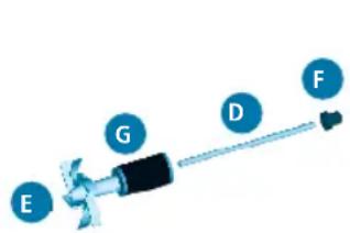

natural_image
3D rendering of a blue industrial cylindrical device with mounting flanges and a protruding bracket (no text or symbols visible)ONDERHOUD
natural_image
3D rendering of a blue industrial cylindrical device with internal components and mounting flanges (no visible text or symbols)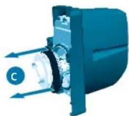
natural_image
3D illustration of a mechanical device with arrows indicating direction (no text or symbols)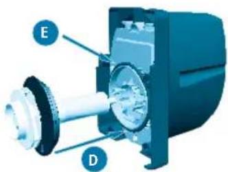

natural_image
3D rendering of a blue industrial cylindrical device with mounting flanges and internal components (no visible text or symbols)ONDERHOUD
natural_image
3D rendering of a mechanical device with internal components and directional arrows (no text or symbols)NL
PT
FLUVAL FX6

natural_image
3D rendered mechanical assembly with two flanged pipes and a central valve (no text or symbols visible)natural_image
Technical line drawing of two mechanical pipe fittings with coiled and flanged ends (no text or symbols)natural_image
3D illustration of a blue mechanical component with a threaded shaft and pipe fitting (no text or symbols)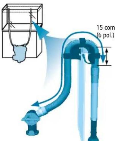
natural_image
Blue industrial pipe fitting with a coiled hose, shown in 3D rendering (no text or symbols)

natural_image
3D rendering of a blue industrial machine with mounting holes and a labeled component (no readable text or symbols beyond branding)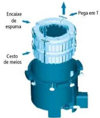
natural_image
3D rendering of a mechanical component with rotational arrows indicating motion (no text or symbols)natural_image
Isometric illustration of a multi-layered mechanical or electronic component with textured surfaces and small bags (no text or symbols)Ilustração de FX4
natural_image
3D rendering of a blue industrial component with inlet and outlet pipes (no readable text or symbols)natural_image
Close-up of a blue mechanical component with a cylindrical shaft and connector (no visible text or symbols)9. Inicie o filtro
natural_image
3D rendering of a blue industrial cylindrical device with labeled ports (FX6, OUT) and internal tubing, shown with a magnified inset showing a cable or connector detail.natural_image
3D rendering of a blue industrial component with labeled part B (no text or symbols on the object itself)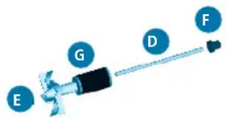

natural_image
3D rendered model of a blue industrial component with mounting flanges and a side-mounted fan (no text or symbols visible)natural_image
3D rendering of a blue industrial cylindrical device with internal components and a separate motor assembly (no text or symbols visible)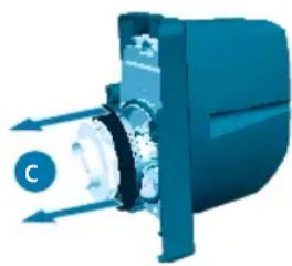
natural_image
3D illustration of a mechanical device with directional arrows indicating motion or flow (no text or symbols)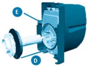

natural_image
3D rendering of a blue industrial cylindrical device with internal components and mounting bracket (no text or symbols visible)MANUTENÇÃO
natural_image
3D rendering of a blue industrial machine with internal components and directional arrows indicating flow or movement (no text or symbols)PT

20500 Trans Canada Hwy, Baie D'Urfé QC H9X 0A2
20500 Trans Canada Hwy
Customer Service Department
Rolf C. Hagen (UK) Ltd
California Drive
Whitwood Industrial Estate,
Castleford WF10 5QH,
West Yorkshire
Tel: 01977 521015
FRANCE
Rolf C. Hagen (France) S.A.
Zone Parisud 4
Boulevard Jean Monnet
F-77388 Combs-la-Ville
Tel: +33 1 64 88 14 18