
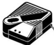
GDR 14.4V Professional - Drill BOSCH - Free user manual and instructions
Find the device manual for free GDR 14.4V Professional BOSCH in PDF.

| Product type | Cordless impact driver |
| Brand | Bosch |
| Model | GDR 14.4 V Professional |
| Rated voltage | 14.4 V |
| No-load speed | 0 - 2,800 rpm |
| Impact rate | 0 - 3,200 impacts/min |
| Max. torque (hard screwdriving) | 135 Nm |
| Assembly screw diameter | M6 - M16 |
| Tool holder | 1/4 inch (6.35 mm) hexagon socket |
| Weight (according to EPTA) | 1.9 kg |
| Power supply | Battery 14.4 V (not included) |
| Recommended battery type | Bosch original |
| Main functions | Screwing and unscrewing, tightening and loosening nuts, impact mechanism, reversible rotation direction, variable speed, adjustable LED light (3 positions) |
| Included accessories | Belt clip, wrist strap (depending on version) |
| Maintenance and cleaning | Clean ventilation slots regularly, replace carbon brushes every 2-3 months if necessary, use only Bosch spare parts |
| Safety | Tool brake (release the switch), torque limiter (impact mechanism), battery locking system, overload protection (battery temperature NTC) |
| Spare parts and repairability | Replaceable carbon brushes, Bosch after-sales service, repair by qualified professional |
| General information | For professional use, use by unauthorized persons prohibited, battery charging temperature: 0°C to 45°C |
Frequently Asked Questions - GDR 14.4V Professional BOSCH
User questions about GDR 14.4V Professional BOSCH
0 question about this device. Answer the ones you know or ask your own.
Ask a new question about this device
Download the instructions for your Drill in PDF format for free! Find your manual GDR 14.4V Professional - BOSCH and take your electronic device back in hand. On this page are published all the documents necessary for the use of your device. GDR 14.4V Professional by BOSCH.
USER MANUAL GDR 14.4V Professional BOSCH
OBJ_DOKU-10211-002.fm Page 1 Monday, November 23, 2009 8:30 AM
natural_image
Illustration of two military-style helicopters with attached gear (no text or symbols)Robert Bosch GmbH
Power Tools Division
70745 LeInfelden-Echterdingen
Germany
www.bosch-pt.com
1 609 929 T16 (2009.11) O / 83 ASIA

GDR | GDS Professional
9,6 V | 12 V | 14,4 V | 18 V

BOSCH
en Original instructions
cn 正本使用说明书
tw日本使用説明書
ko사용 선정서 원문
th
GDS ...GDR ...
1 609 929 T16 | (23.11.09) Bosch Power Tools
5 |
1 609 929 T16 | (23.11.09) Bosch Power Tools
6 | English
Safety Notes
General Power Tool Safety Warnings
WARNING
Read all safety warnings and all instructions. Failure to follow
the warnings and instructions may result in electric shock, fire and/or serious injury.
Save all warnings and instructions for future reference.
The term "power tool" in the warnings refers to your mains-operated (corded) power tool or battery-operated (cordless) power tool.
1) Work area safety
a) Keep work area clean and well lit. Cluttered or dark areas invite accidents.
b) Do not operate power tools in explosive atmospheres, such as in the presence of flammable liquids, gases or dust. Power tools create sparks which may ignite the dust or fumes.
c) Keep children and bystanders away while operating a power tool. Distractions can cause you to lose control.
2) Electrical safety
a) Power tool plugs must match the outlet. Never modify the plug in any way. Do not use any adapter plugs with earthed (grounded) power tools. Unmodified plugs and matching outlets will reduce risk of electric shock.
b) Avoid body contact with earthed or grounded surfaces, such as pipes, radiators, ranges and refrigerators. There is an increased risk of electric shock if your body is earthed or grounded.
c) Do not expose power tools to rain or wet conditions. Water entering a power tool will increase the risk of electric shock.
d) Do not abuse the cord. Never use the cord for carrying, pulling or unplugging the power tool. Keep cord away from heat, oil, sharp edges and moving parts. Damaged or entangled cords increase the risk of electric shock.
e) When operating a power tool outdoors, use an extension cord suitable for outdoor use. Use of a cord suitable for outdoor use reduces the risk of electric shock.
f) If operating a power tool in a damp location is unavoidable, use a residual current device (RCD) protected supply. Use of an RCD reduces the risk of electric shock.
3) Personal safety
a) Stay alert, watch what you are doing and use common sense when operating a power tool. Do not use a power tool while you are tired or under the influence of drugs, alcohol or medication. A moment of inattention while operating power tools may result in serious personal injury.
b) Use personal protective equipment. Always wear eye protection. Protective equipment such as dust mask, non-skid safety shoes, hard hat, or hearing protection used for appropriate conditions will reduce personal injuries.
c) Prevent unintentional starting. Ensure the switch is in the off-position before connecting to power source and/or battery pack, picking up or carrying the tool. Carrying power tools with your finger on the switch or energising power tools that have the switch on invites accidents.
d) Remove any adjusting key or wrench before turning the power tool on. A wrench or a key left attached to a rotating part of the power tool may result in personal injury.
e) Do not overreach. Keep proper footing and balance at all times. This enables better control of the power tool in unexpected situations.
f) Dress properly. Do not wear loose clothing or jewellery. Keep your hair, clothing and gloves away from moving parts.
Loose clothes, jewellery or long hair can be caught in moving parts.
g) If devices are provided for the connection of dust extraction and collection facilities, ensure these are connected and properly used. Use of dust collection can reduce dust-related hazards.
4) Power tool use and care
a) Do not force the power tool. Use the correct power tool for your application. The correct power tool will do the job better and safer at the rate for which it was designed.
b) Do not use the power tool if the switch does not turn it on and off. Any power tool that cannot be controlled with the switch is dangerous and must be repaired.
c) Disconnect the plug from the power source and/or the battery pack from the power tool before making any adjustments, changing accessories, or storing power tools. Such preventive safety measures reduce the risk of starting the power tool accidentally.
d) Store idle power tools out of the reach of children and do not allow persons unfamiliar with the power tool or these instructions to operate the power tool. Power tools are dangerous in the hands of untrained users.
e) Maintain power tools. Check for misalignment or binding of moving parts, breakage of parts and any other condition that may affect the power tool's operation. If damaged, have the power tool repaired before use. Many accidents are caused by poorly maintained power tools.
f) Keep cutting tools sharp and clean. Properly maintained cutting tools with sharp cutting edges are less likely to bind and are easier to control.
g) Use the power tool, accessories and tool bits etc. in accordance with these instructions, taking into account the working conditions and the work to be performed. Use of the power tool for operations different from those intended could result in a hazardous situation.
5) Battery tool use and care
a) Recharge only with the charger specified by the manufacturer. A charger that is suitable for one type of battery pack may create a risk of fire when used with another battery pack.
b) Use power tools only with specifically designated battery packs. Use of any other battery packs may create a risk of injury and fire.
c) When battery pack is not in use, keep it away from other metal objects, like paper clips, coins, keys, nails, screws or other small metal objects, that can make a connection from one terminal to another. Shorting the battery terminals together may cause burns or a fire.
d) Under abusive conditions, liquid may be ejected from the battery; avoid contact. If contact accidentally occurs, flush with water. If liquid contacts eyes, additionally seek medical help. Liquid ejected from the battery may cause irritation or burns.
6) Service
a) Have your power tool serviced by a qualified repair person using only identical replacement parts. This will ensure that the safety of the power tool is maintained.
Safety Warnings for Screwdriver
Hold power tool by insulated gripping surfaces, when performing an operation where the fastener may contact hidden wiring. Fasteners contacting a "live" wire may make exposed metal parts of the power tool "live" and could give the operator an electric shock.
- Secure the workpiece. A workpiece clamped with clamping devices or in a vice is held more secure than by hand.
▶ Always wait until the machine has come to a complete stop before placing it down. The tool insert can jam and lead to loss of control over the power tool.
▶ Do not open the battery. Danger of short-circuiting.
8 | English

Protect the battery against heat, e. g., against continuous intense sunlight, fire, water, and moisture. Danger of explosion.
▶ Use only original Bosch batteries with the voltage listed on the nameplate of your power tool. When using other batteries, e. g. imitations, reconditioned batteries or other brands, there is danger of injury as well as property damage through exploding batteries.
Functional Description

Read all safety warnings and all instructions. Failure to follow the warnings and instructions may result in electric shock, fire and/or serious injury.
While reading the operating instructions, unfold the graphics page for the machine and leave it open.
Intended Use
The machine is intended for driving in and loosening screws and bolts as well as for tightening and loosening nuts within the respective range of dimension.
Product Features
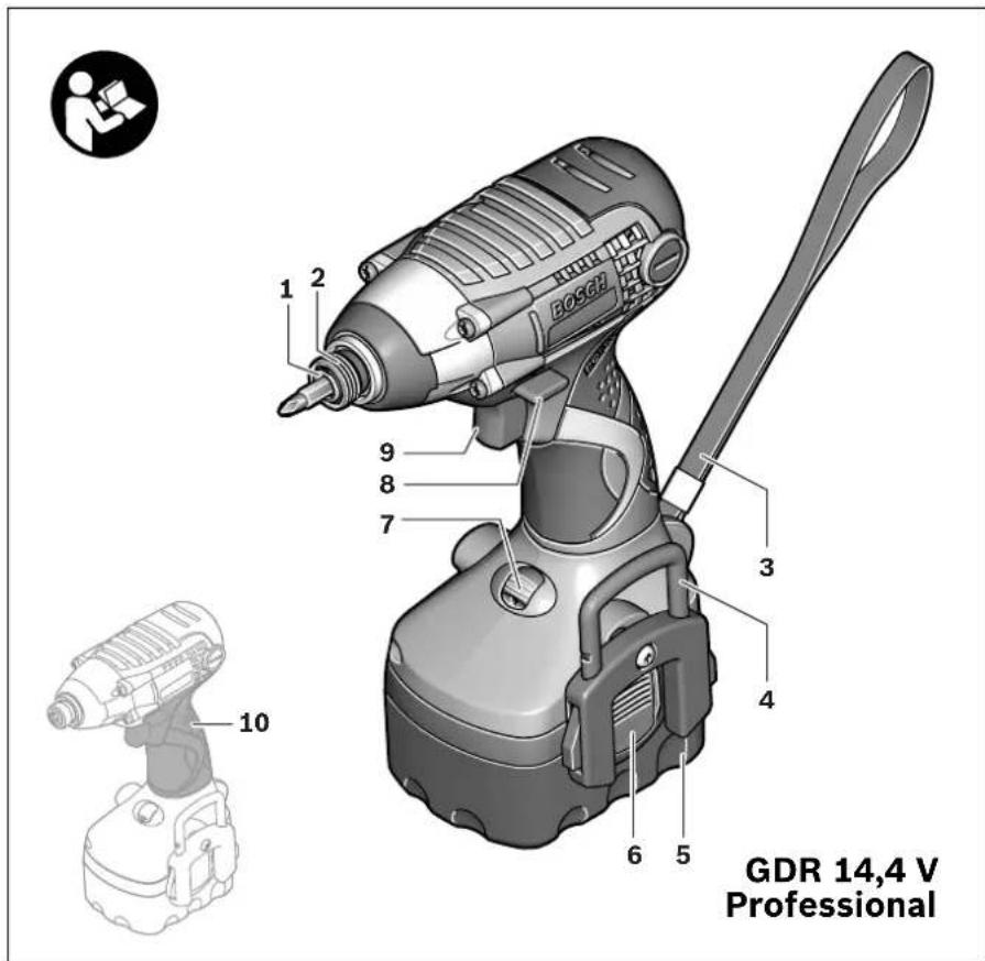
The numbering of the product features refers to the illustration of the machine on the graphics page.
1 Tool holder
2 Locking sleeve
3 Carrying strap
4 Belt clip*
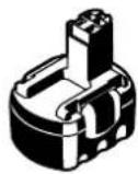
5 Battery*
6 Battery unlocking button
7 Knurled thumbwheel with LED indicator*
8 Rotational direction switch
9 On/Off switch
10 Handle (insulated gripping surface)
11 Screwdriver bit with ball catch*
12 Universal bit holder*
13 Screwdriver bit*
14 Carbon brushes
15 Cover lid
*Accessories shown or described are not part of the standard delivery scope of the product. A complete overview of accessories can be found in our accessories program.
Technical Data
| Cordless Impact Screwdriver GDR 9,6 V | GDR 12 V | GDR 14,4 V | GDR 18 V | ||
| Professional | Professional | Professional | Professional | Professional | |
| Article number | 0 601 909 6.. 0 601 909 5.. 0 601 909 4.. 0 601 909 3.. | ||||
| Rated voltage | V= 9.6 12 14.4 18 | ||||
| No-load speed | min ^-1 | 0 -2800 0 -2800 0 -2800 0 -2800 | |||
| Impact rate | min ^-1 | 0 -3200 0 -3200 0 -3200 0 -3200 | |||
| Maximum torque, hard screw-driving application according to ISO 5393 | Nm 105 125 135 155 | ||||
| Bolt size | mm | M6-M12 | M6-M14 | M6-M16 | M6-M20 |
| Tool holder | 14" hexagon socket | 14" hexagon socket | 14" hexagon socket | 14" hexagon socket | |
| Weight according to EPTA-Procedure 01/2003 | kg 1.6 1.8 1.9 2.1 | ||||
English
|9
| Cordless Impact Screwdriver GDS 12 V | GDS 14,4 V | GDS 18 V | ||
| Professional | Professional | Professional | ||
| Article number | 0 601 909 K.. | 0 601 909 H.. | 0 601 909 F.. | |
| Rated voltage | V= 12 14,4 18 | |||
| No-load speed | min-1 | 0 - 2 8 0 0 | 0 -2800 0 -2800 | |
| Impact rate | min-1 | 0 - 3 2 0 0 | 0 -3200 0 -3200 | |
| Maximum torque, hard screwdriving application according to ISO 5393 | Nm | 175 | 200 | 220 |
| Bolt size | mm | M6-M14 | M6-M16 | M6-M20 |
| Tool holder | ■ 1/2" | ■ 1/2" | ■ 1/2" | |
| Weight according to EPTA-Procedure 01/2003 | kg | 1.8 | 1.9 | 2.2 |
| Please observe the article number on the type plate of your machine. The trade names of the individual machines may vary. | ||||
Assembly
Battery Charging
A battery that is new or has not been used for a longer period does not develop its full capacity until after approx. 5 charging/discharging cycles.
To remove the battery 5 press the unlocking buttons 6 and pull out the battery downwards. Do not exert any force.
The battery is equipped with a NTC temperature control which allows charging only within a temperature range of between 0 °C and 45 °C. A long battery service life is achieved in this manner.
A significantly reduced working period after charging indicates that the battery is used and must be replaced.
Observe the notes for disposal.
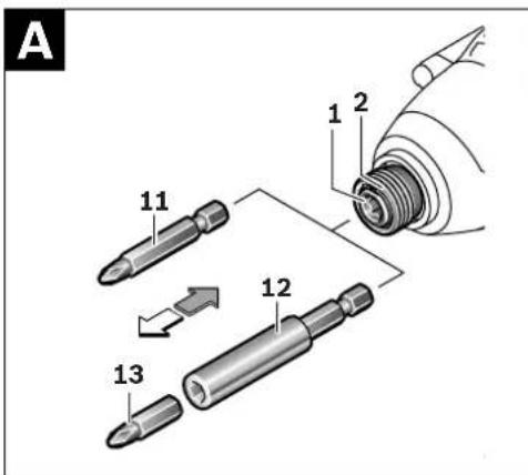
Changing the Tool (see figure A)
Before any work on the machine (e.g., maintenance, tool change, etc.) as well as during transport and storage, set the rotational direction switch to the centre position. Unintentional actuation of the On/Off switch can lead to injuries.
GDR 9,6 V/GDR 12 V/GDR 14,4 V/GDR 18 V: Inserting
Pull the locking sleeve 2 forward, push the insert tool to the stop into the tool holder 1 and release the locking sleeve 2 to lock the insert tool.
Use only screwdriver bits with ball catch 11 (DIN 3126-E6.3). Other screwdriver bits 13 can be used with a universal bit holder with ball catch 12.
Removing
Pull the locking sleeve 2 forward and remove the insert tool.
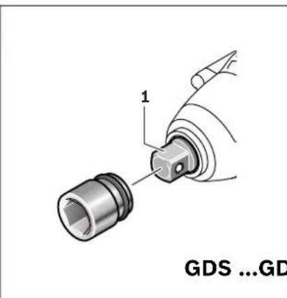
GDS 12 V/GDS 14,4 V/GDS 18 V:
When working with an application tool, pay attention that the application tool is firmly seated on the tool holder. When the application tool is not firmly connected with the tool holder, it can come loose again and not be controlled.
Slide the application tool onto the square drive of the tool holder 1.
10 | English
Operation
Method of Operation
The tool holder 1 with the tool is driven by an electric motor via a gear and impact mechanism.
The working procedure is divided into two phases:
Screwing in and tightening (impact mechanism in action).
The impact mechanism is activated as soon as the screwed connection runs tight and thus load is put on the motor. In this instance, the impact mechanism converts the power of the motor to steady rotary impacts. When loosening screws or nuts, the process is reversed.
Starting Operation
Inserting the Battery
▶ Use only original Bosch O-pack batteries with the voltage given on the type plate of your machine. The use of other batteries can lead to injuries and danger of fire.
Set the rotational direction switch 8 to the centre position in order to avoid unintentional starting. Insert the charged battery 5 into the handle so that it can be felt to engage and faces flush against the handle.
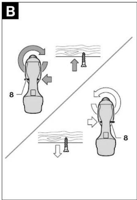
Reversing the Rotational Direction (see figure B)
The rotational direction switch 8 is used to reverse the rotational direction of the machine. However, this is not possible with the On/Off switch 9 actuated.
Right rotation: For driving in screws and tightening nuts, press the rotational direction switch 8 through to the left stop.
Left Rotation: For loosening and unscrewing screws and nuts, press the rotational direction switch 8 through to the right stop.
Switching On and Off
To start the machine, press the On/Off switch 9 and keep it pressed.
To switch off the machine, release the On/Off switch 9.
Adjusting the Speed
The speed of the switched on power tool can be variably adjusted, depending on how far the On/Off switch 9 is pressed.
Light pressure on the On/Off switch 9 results in a low rotational speed. Further pressure on the switch results in an increase in speed.
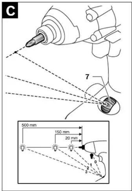
Swivel Lighting System (see figure C)
Your tool is equipped with a light source in the knurled thumbwheel 7. The light is activated as soon as the knurled thumbwheel 7 is in position 1 - 3 and the On/Off switch 9 is pressed.
Depending on the bit being used, the light beam can be adjusted to three positions by turning the knurled thumbwheel 7. In position 1, the focus of the light beam is approx. 20 mm, in position 2 approx. 150 mm and in position 3 approx. 500 mm in front of the tool holder 1. In the "OFF" position, the light is switched off permanently.
Working Advice
- Apply the power tool to the screw/nut only when it is switched off. Rotating tool inserts can slip off.
The torque depends on the impact duration. The maximum achieved torque results from the sum of all individual torques achieved through impact. The maximum torque is achieved after an impact duration of 6–10 seconds. After this duration, the tightening torque is increased only minimally.
The impact duration is to be determined for each required tightening torque. The actually achieved tightening torque is always to be checked with a torque wrench.
Screw Applications with Hard, Spring-loaded or Soft Seat
When in a test, the achieved torques in an impact series are measured and transferred into a diagram, resulting in the curve of a torque characteristic. The height of the curve corresponds with the maximum reachable torque, and the steepness indicates the duration in which this is achieved.
A torque gradient depends on the following factors:
- Strength properties of the screws/nuts
- Type of backing (washer, disc spring, seal)
- Strength properties of the material being screwed/bolted together
– Lubrication conditions at the screw/bolt connection
The following application cases result accordingly:
- A hard seat is given for metal-to-metal screw applications with the use of washers. After a relatively short impact duration, the maximum torque is reached (steep characteristic curve). Unnecessary long impact duration only causes damage to the machine.
- A spring-loaded seat is given for metal-to-metal screw applications, however with the use of spring washers, disc springs, studs or screws/nuts with conical seat as well as when using extensions.
- A soft seat is given for screw applications, e. g., metal on wood or when using lead washers or fibre washers as backing.
For a spring-loaded seat as well as for a soft seat, the maximum tightening torque is lower than for a hard seat. Also, a clearly longer impact duration is required.
Reference Values for Maximum Screw/Bolt Tightening Torques
Calculated from the tensional cross-section; utilization of the yield point 90% (with friction coefficient _total = 0.12 ). As a control measure, always check the tightening torque with a torque wrench.
| Property Classes according to DIN 267 | Standard Screws/Bolts High-strength Bolts | ||||||||||
| 3.6 | 4.6 | 5.6 | 4.8 | 6.6 | 5.8 | 6.8 | 6.9 | 8.8 | 10.9 | 12.9 | |
| M 6 | 2.71 | 3.61 | 4.52 | 4.8 | 5.42 | 6.02 | 7.22 | 8.13 | 9.7 | 13.6 | 16.2 |
| M 8 | 6.57 | 8.7 | 11 | 11.6 | 13.1 | 14.6 | 17.5 | 19.7 | 23 | 33 | 39 |
| M 10 | 13 | 17.5 | 22 | 23 | 26 | 29 | 35 | 39 | 47 | 65 | 78 |
| M 12 | 22.6 | 30 | 37.6 | 40 | 45 | 50 | 60 | 67 | 80 | 113 | 135 |
| M 14 | 36 48 60 65 72 | 79 95 107 130 180 215 | |||||||||
| M 16 | 55 73 92 98 110 122 147 | 165 196 275 330 | |||||||||
| M 18 | 75 101 126 135 | 151 168 202 227 270 380 450 | |||||||||
| M 20 | 107 143 178 190 214 238 | 286 320 385 540 635 | |||||||||
Tips
Before screwing larger, longer screws into hard materials, it is advisable to predrill a pilot hole with the core diameter of the thread to approx. ^2/_3 of the screw length.
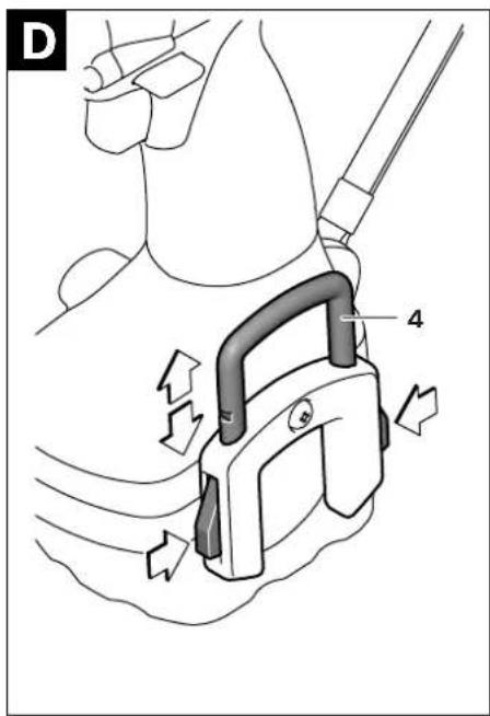
Belt Clip (see figure D)
With the belt clip 4, the machine can be hung onto a belt. The user has both hands free and the machine is always at hand.
The belt clip 4 can be attached and screwed to either side of the machine.
The belt clip 4 will automatically draw out when pressing both release buttons. To dismount the belt clip 4, remove the complete unit by un-screwing the fastening screw.
Always tighten the fastening screw after mounting the belt clip 4.
12 | English
Maintenance and Service
Maintenance and Cleaning
Before any work on the machine (e.g., maintenance, tool change, etc.) as well as during transport and storage, set the rotational direction switch to the centre position. Unintentional actuation of the On/Off switch can lead to injuries.
▶ For safe and proper working, always keep the machine and ventilation slots clean.
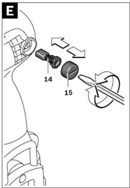
Replacing the Carbon Brushes (see figure E)
Check the length of the carbon brushes approx. every 2–3 months and replace the carbon brushes if required.
Never replace only a single carbon brush!
Criteria for replacement of the carbon brushes: A dotted or broken line is visible on one of the large side surfaces of each carbon brush. When either of both carbon brushes is used up to this line, then both carbon brushes should be replaced immediately in order to protect the armature against possible damage.
Note: Use only carbon brushes supplied by Bosch and intended specifically for your product.
- Unscrew the caps 15 using a suitable screw-driver.
- Replace the spring-loaded carbon brushes 14 and screw the caps back on again.
If the machine should fail despite the care taken in manufacturing and testing procedures, repair should be carried out by an after-sales service centre for Bosch power tools.
In all correspondence and spare parts order, please always include the 10-digit article number given on the type plate of the machine.
After-sales Service and Customer Assistance
Our after-sales service responds to your questions concerning maintenance and repair of your product as well as spare parts. Exploded views and information on spare parts can also be found under:
www.bosch-pt.com
Our customer service representatives can answer your questions concerning possible applications and adjustment of products and accessories.
People's Republic of China
Website: www.bosch-pt.com.cn
China Mainland
Bosch Power Tools (China) Co., Ltd.
567, Bin Kang Road
Bin Jiang District 310052
Hangzhou, P.R.China
Service Hotline: 800 8 20 84 84
Tel.: +86 (571) 87 77 43 38
Fax: +86 (571) 87 77 45 02
HK and Macau Special Administrative Regions
Robert Bosch Hong Kong Co. Ltd.
21st Floor, 625 King's Road
North Point, Hong Kong
Customer Service Hotline: +852 (21) 02 02 35
Fax: +852 (25) 90 97 62
E-Mail: info@hk.bosch.com
www.bosch-pt.com.cn
Indonesia
PT. Multi Tehaka
Kawasan Industri Pulogadung
Jalan Rawa Gelam III No. 2
Jakarta 13930
Indonesia
Tel.: +62 (21) 4 60 12 28
Fax: +62 (21) 46 82 68 23
E-Mail: sales@multitehaka.co.id
www.multitehaka.co.id
Phillippines
Robert Bosch, Inc.
Zuellig Building
Sen. Gil Puyat Avenue
Makati City 1200, Metro Manila
Philippines
Tel.: +63 (2) 8 17 32 31
www.bosch.com.ph
Malaysia
Robert Bosch (SEA.) Pte. Ltd.
No. 8a, Jalan 13/6
46200 Petaling Jaya,
Selangor,
Malaysia
Tel.: +6 (03) 7966 3000
Fax: +6 (03) 7958 3838
E-Mail: hengsiang.yu@my.bosch.com
Toll Free Tel.: 1 800 880 188
Fax: +6 (03) 7958 3838
www.bosch.com.sg
Thailand
Robert Bosch Ltd.
Liberty Square Building
No. 287, 11 Floor
Silom Road, Bangrak
Bangkok 10500
Tel.: +66 (2) 6 31 18 79 - 18 88 (10 lines)
Fax: +66 (2) 2 38 47 83
Robert Bosch Ltd., P. O. Box 2054
Bangkok 10501, Thailand
Bosch Service – Training Centre
2869-2869/1 Soi Ban Kluay
Rama IV Road (near old Paknam Railway)
Prakanong District
10110 Bangkok
Thailand
Tel.: +66 (2) 6 71 78 00 - 4
Fax: +66 (2) 2 49 42 96
Fax: +66 (2) 2 49 52 99
Singapore
Robert Bosch (SEA.) Pte. Ltd.
38 C Jalan Pemimpin
Singapore 915701
Republic of Singapore
Tel.: +65 (3) 50 54 94
Fax: +65 (3) 50 53 27
www.bosch.com.sg
Vietnam
Robert Bosch (SEA) Pte. Ltd - Vietnam
Representative Office
Saigon Trade Center, Suite 1206
37 Ton Duc Thang Street,
Ben Nghe Ward, District 1
HCMC
Vietnam
Tel.: +84 (8) 9111 374 - 9111 375
Fax: +84 (8) 9111376
Australia, New Zealand and Pacific Islands
Robert Bosch Australia Pty. Ltd.
Power Tools
Locked Bag 66
Clayton South VIC 3169
Customer Contact Center
Inside Australia:
Phone: +61 (01300) 307 044
Fax: + 61 (01300) 307 045
Inside New Zealand:
Phone: +64 (0800) 543 353
Fax: +64 (0800) 428 570
Outside AU and NZ:
Phone: +61 (03) 9541 5555
www.bosch.com.au
Disposal
The machine, accessories and packaging should be sorted for environmental-friendly recycling.
Battery packs/batteries:
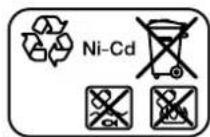
Ni-Cd: Nickel cadmium
Warning: These battery packs contain cadmium, a highly toxic heavy metal.
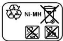
Ni-MH: Nickel metal hydride
Do not dispose of battery packs/batteries into household waste, fire or water. Battery packs/batteries should be collected, recycled or disposed of in an environmental-friendly manner.
Subject to change without notice.
14|中文
安全规章
电动工具通用安全警告

Robert Bosch Korea Mechanics and Electronics Ltd.
전동공구 사업부
คํา Comparison Measure provides training fees, including expenses and other expenses.
| ระดับคุณสมบัติตาม | สกรู/ใบล์ทมาตรฐาน | ใบล์ทความแข็งสูง | |||||||||
| DIN 267 | 3.6 | 4.6 | 5.6 | 4.8 | 6.6 | 5.8 | 6.8 | 6.9 | 8.8 | 10.9 | 12.9 |
| M 6 | 2.71 | 3.61 | 4.52 | 4.8 | 5.42 | 6.02 | 7.22 | 8.13 | 9.7 | 13.6 | 16.2 |
| M 8 | 6.57 | 8.7 | 11 | 11.6 | 13.1 | 14.6 | 17.5 | 19.7 | 23 | 33 | 39 |
| M 10 | 13 | 17.5 | 22 | 23 | 26 | 29 | 35 | 39 | 47 | 65 | 78 |
| M 12 | 22.6 | 30 | 37.6 | 40 | 45 | 50 | 60 | 67 | 80 | 113 | 135 |
| M 14 | 36 | 48 | 60 | 65 | 72 | 79 | 95 | 107 | 130 | 180 | 215 |
| M 16 | 55 | 73 | 92 | 98 | 110 | 122 | 147 | 165 | 196 | 275 | 330 |
| M 18 | 75 | 101 | 126 | 135 | 151 | 168 | 202 | 227 | 270 | 380 | |
| M 20 | 107 | 143 | 178 | 190 | 214 | 238 | 286 | 320 | 385 | 540 | 635 |
1 609 929 T16 | (23.11.09) Bosch Power Tools
ภาษาไทย
คำแนะนำ
Jalan Rawa Gelam III No. 2
Jakarta 13930
Indonesia
Tel.: +62 (21) 4 60 12 28
Fax: +62 (21) 46 82 68 23
E-Mail: sales@multitehaka.co.id
www.multitehaka.co.id
Cara membuang
natural_image
Isometric line drawing of a Bosch electrical connector (no text or symbols)GDR 9,6 V
GDR 12 V
GDR 14,4 V
GDS 12 V
GDS 14,4 V:
2 605 438 162
GDR 12 V
GDS 18 V
2 605 100 462
9,6 V (NiMH)
2 607 335 682 (2,6 Ah)
12 V (NiMH)
2 607 335 684 (2,6 Ah)
2 607 335 692 (3,0 Ah)
14,4 V (NiMH)
2 607 335 686 (2,6 Ah)
2 607 335 694 (3,0 Ah)
18 V (NiMH)
2 607 335 688 (2,6 Ah)
2 607 335 696 (3,0 Ah)
AL 1450 DV
(7,2 - 14,4 V)
2 607 224 702 (Far East, IN)
2 607 224 714 (KR)
AL 2450 DV
(7,2 - 24 V)
2 607 225 028 (Far East, IN)
2 607 225 030 (HK, MY, SG)
2 607 225 040 (KR)