
VMA401 - TV Stand SANUS - Free user manual and instructions
Find the device manual for free VMA401 SANUS in PDF.


User questions about VMA401 SANUS
0 question about this device. Answer the ones you know or ask your own.
Ask a new question about this device
Download the instructions for your TV Stand in PDF format for free! Find your manual VMA401 - SANUS and take your electronic device back in hand. On this page are published all the documents necessary for the use of your device. VMA401 by SANUS.
USER MANUAL VMA401 SANUS
natural_image
3D technical line drawing of a device with a rectangular housing and a flat base labeled 'BANUS' (no other text or symbols)We're here to help!
If you have any questions along the way, just give us a call.
Americas: 800-359-5520 • info@sanus.com • Leave a review: sanus.com
UK: 0800 056 2853
Europe, Middle East, and Africa: +31 (0) 495 580 852 • europe.sanus@milestone.com
SANUS • 6436 City West Parkway • Eden Prairie, MN 55344 USA
©2014 Milestone AV Technologies. All rights reserved. Sanus is a division of Milestone. All other brand names or marks are used for identification purposes and are trademarks of their respective owners.
6901-002141 05
English - How to use this manual
For best results, reference both the text and illustrations.

Select one item or the other.

This item is optional
English Text Pages 3-11
IMPORTANT SAFETY INSTRUCTIONS – SAVE THESE INSTRUCTIONS – PLEASE READ ENTIRE MANUAL PRIOR TO USE
Specifications
Weight capacity-DO NOT EXCEED: 6.8 kg (15 lb)
Level: ±7½°
CAUTION: Avoid potential personal injuries and property damage!
Do not use this product for any purpose not explicitly specified by manufacturer.
Do not place objects heavier than 6.8 kg (15 lb) on shelf.
Do not place a TV on shelf.
Do not allow children to climb or hang on shelf.
If you do not understand these instructions, or have doubts about the safety of the installation, assembly or use of this product, contact Customer Service or call a qualified contractor.
Manufacturer is not responsible for damage or injury caused by incorrect assembly or use.
Features and Benefits
The VMA401:
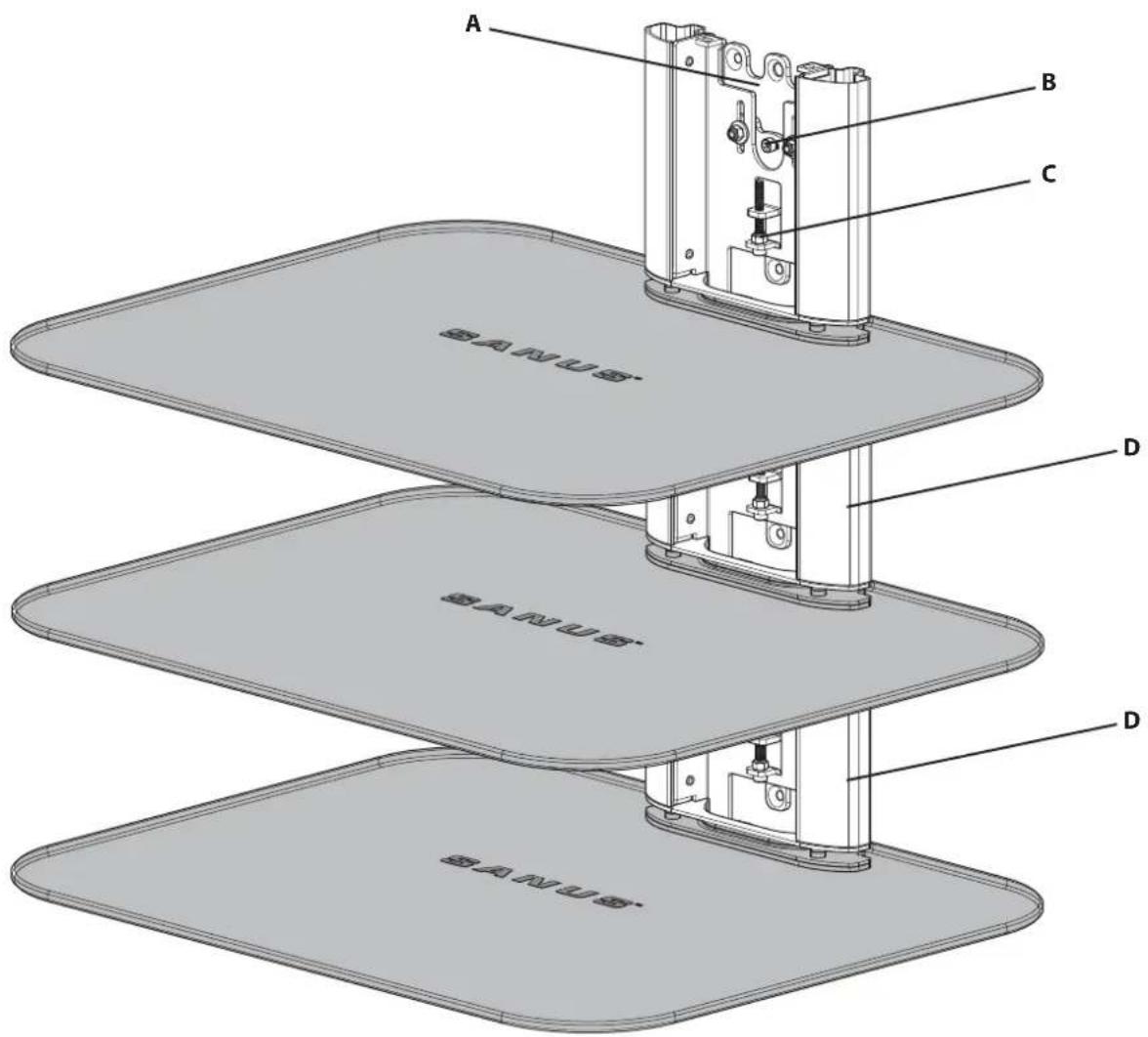
A. Can be mounted to drywall, wood stud, or concrete.
B. Level can be adjusted by ±7½° post-installation.
C. Height can be adjusted by 1 in. post-installation.
D. Is stackable to accommodate multiple components (not to exceed 6.8 kg (15 lb) on each shelf).
text_image
A B C BANUS D BANUS D BANUSRequired Tools

text_image
11 mm (7/16 in.) 3 mm (1/8 in.) 10 mm (3/8 in.) 10 mm (3/8 in.)Supplied Parts and Hardware
WARNING: This product contains small items that could be a choking hazard if swallowed.
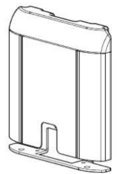
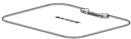
Before starting assembly, verify all parts are included and undamaged. If any parts are missing or damaged, do not return the damaged item to your dealer; contact Customer Service. Never use damaged parts!
natural_image
Technical line drawing of a mechanical housing or enclosure component (no text or symbols)[01] × 1
text_image
截止2015年度[02] × 1
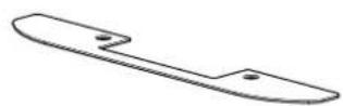
[03] × 1

1/4 × 2 ½ in.

8 x 2 in.
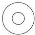
[06] × 1
[04] × 1 [05] × 3
natural_image
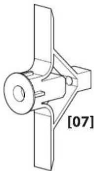
Technical line drawing of a mechanical component with no visible text or symbols[07] × 3
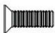
M5×20 M5×6
[08] × 2

[09] × 2
text_image
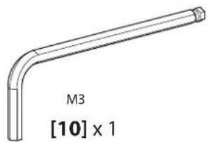
M3 [10] x 1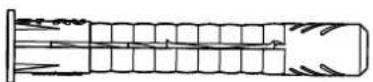
[11]×1
1-1 Single shelf configuration

Your VMA401 is 166 mm (6 ^3/5 in.) high. Consider this when determining wall placement.
See 1-2 for configuration of multiple units.
1-2 Stacked configuration
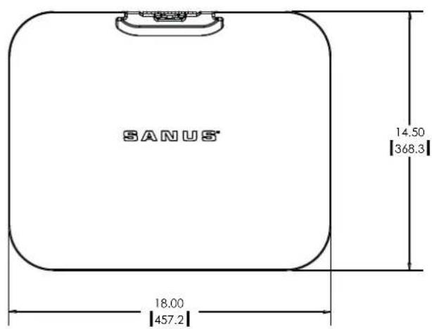
text_image
SANUS 18.00 [457.2] 14.50 [368.3]Your VMA401 is 166 mm (6 ^3/5 in.) high. Consider this when determining wall placement.
IMPORTANT: Begin stacking your VMA401 shelves from the top down.
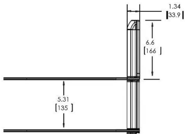
text_image
1.34 [33.9] 6.6 [166] 5.31 [135]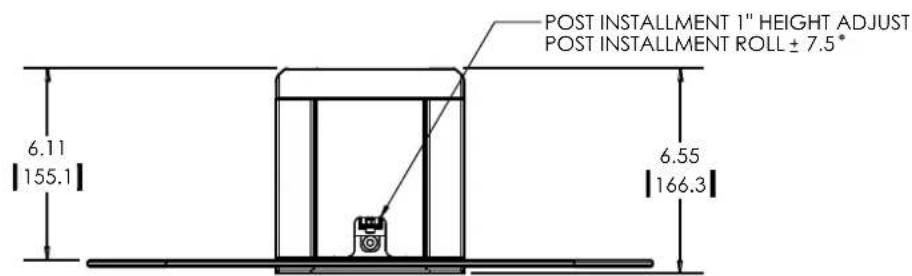
text_image
POST INSTALLMENT 1" HEIGHT ADJUST POST INSTALLMENT ROLL ± 7.5° 6.11 155.1 6.55 166.36901-002141 05
2 Mount the Wall Plate
Wood stud

text_image
11 mm (7/16 in.) 3 mm (1/8 in.)2-1 Locate stud
text_image
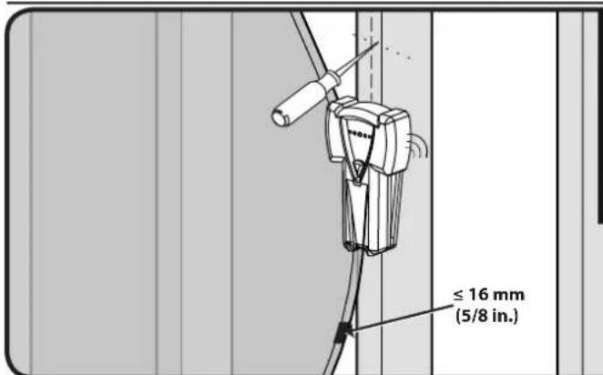
≤ 16 mm (5/8 in.)Verify the center of the stud using an awl, a thin nail, or an edge to edge stud finder.
CAUTION: Avoid potential personal injuries and property damage!
Drywall covering the wall must not exceed 16 mm (5/8 in.).
Minimum wood stud size: common 51 x 102 mm (2 x 4 in.) nominal 38 x 89 mm (1½ x 3½ in.).
2-2 Mark the wall
text_image
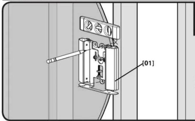
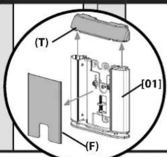
[01]IMPORTANT: For stacking configurations, stack from the top down. Remove the front (F) and top (T) covers from the wall plate [01]. Level the wall plate [01] and mark the hole locations.
text_image
(T) [01] (F)2-3 Drill pilot holes
natural_image
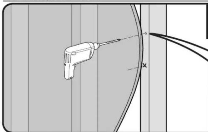
Technical line drawing of a tool with a screwdriver, shown against a grid background (no text or symbols)CAUTION: Avoid potential injuries or property damage! Pilot holes MUST be drilled to a depth of 63.5 mm (2½ in.) using a 3 mm (1/8 in.) diameter drill bit.
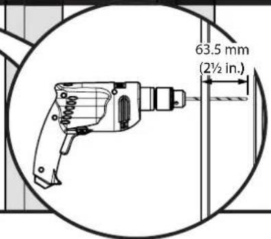
text_image
63.5 mm (2½ in.)2-4 Tighten lag bolt and screw
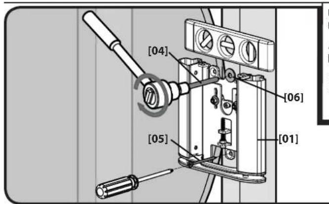
text_image
[04] [06] [05] [01]Use the lag bolt [04] and washer [06] to secure the top of the wall plate. Use the #8 screw [05] to secure the bottom of the wall plate.
⚠️ CAUTION: Improper use could reduce the holding power of the lag bolt. To avoid potential injuries or property damage
■ DO NOT over-tighten the lag bolt [04] or the screw [05].
- Tighten the lag bolt [04] only until the washer [06] is pulled firmly against the wall plate [01].
2 Mount the Wall Plate
Solid concrete or concrete block

text_image
10 mm (3/8 in.)2-1 Mark the wall
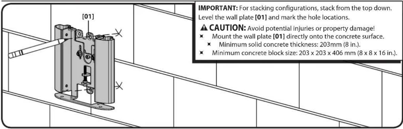
text_image
[01] IMPORTANT: For stacking configurations, stack from the top down. Level the wall plate [01] and mark the hole locations. ▲ CAUTION: Avoid potential injuries or property damage! ■ Mount the wall plate [01] directly onto the concrete surface. ■ Minimum solid concrete thickness: 203mm (8 in.). ■ Minimum concrete block size: 203 x 203 x 406 mm (8 x 8 x 16 in.).2-2 Drill pilot holes
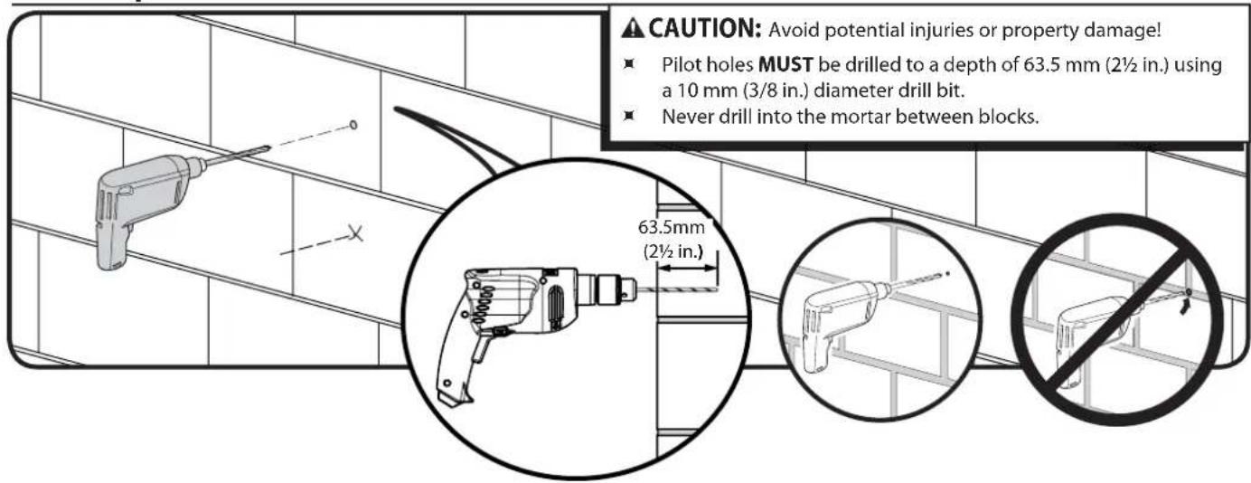
text_image
CAUTION: Avoid potential injuries or property damage! ■ Pilot holes MUST be drilled to a depth of 63.5 mm (2½ in.) using a 10 mm (3/8 in.) diameter drill bit. ■ Never drill into the mortar between blocks. 63.5mm (2½ in.)2-3 Insert anchors and screws
text_image
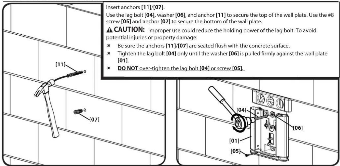
Insert anchors [11]/[07]. Use the lag bolt [04], washer [06], and anchor [11] to secure the top of the wall plate. Use the #8 screw [05] and anchor [07] to secure the bottom of the wall plate. ⚠️ CAUTION: Improper use could reduce the holding power of the lag bolt. To avoid potential injuries or property damage: ■ Be sure the anchors [11]/[07] are seated flush with the concrete surface. ■ Tighten the lag bolt [04] only until the washer [06] is pulled firmly against the wall plate [01]. ■ DO NOT over-tighten the lag bolt [04] or screw [05].2 Mount the Wall Plate
Drywall

text_image
10 mm (3/8 in.)2-1 Mark the wall
text_image
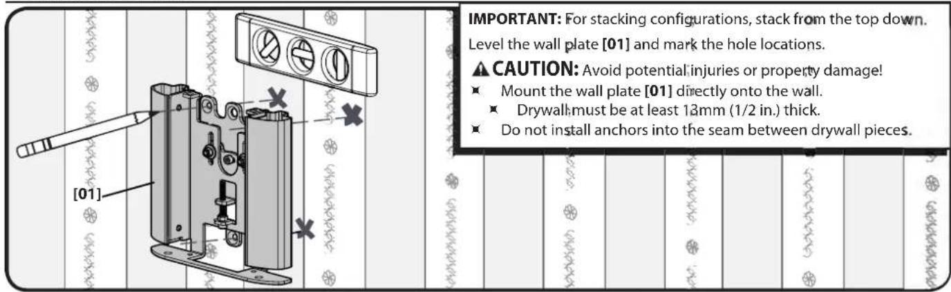
IMPORTANT: For stacking configurations, stack from the top down. Level the wall plate [01] and mark the hole locations. CAUTION: Avoid potential injuries or property damage! • Mount the wall plate [01] directly onto the wall. • Drywall must be at least 13mm (1/2 in.) thick. • Do not install anchors into the seam between drywall pieces.2-2 Drill pilot holes
text_image
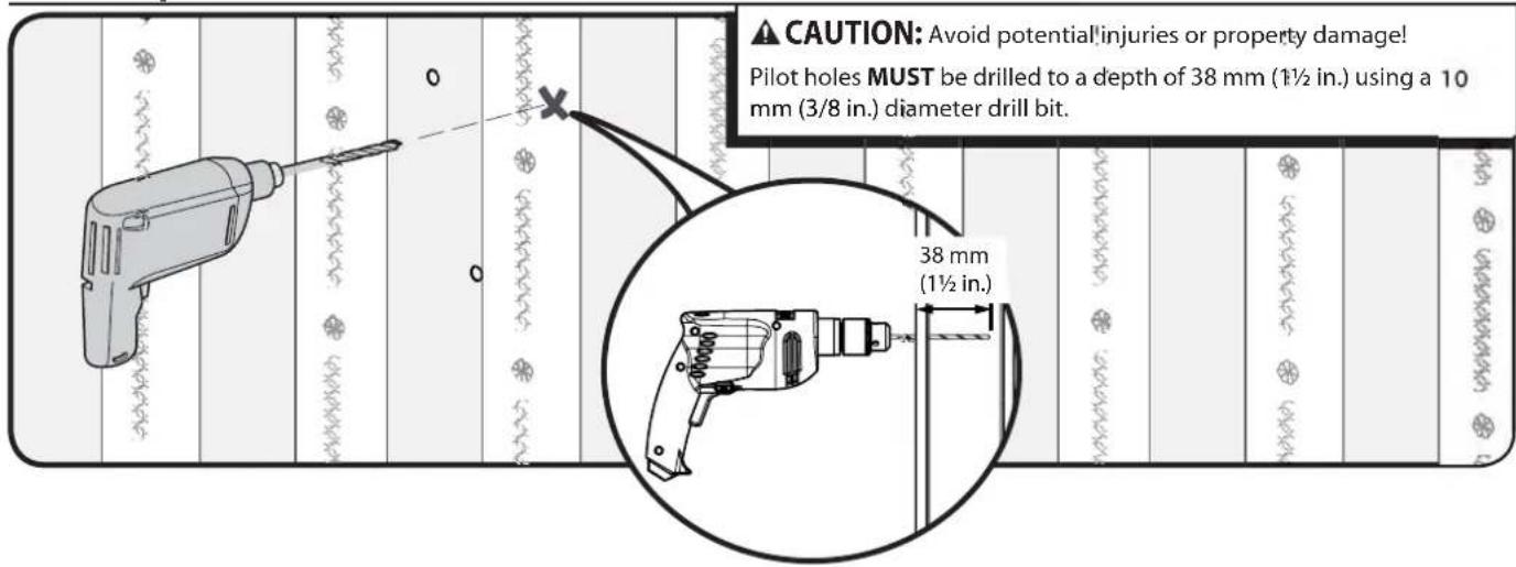
CAUTION: Avoid potential injuries or property damage! Pilot holes MUST be drilled to a depth of 38 mm (1½ in.) using a 10 mm (3/8 in.) diameter drill bit. 38 mm (1½ in.)2-3 Insert anchors and screws
text_image
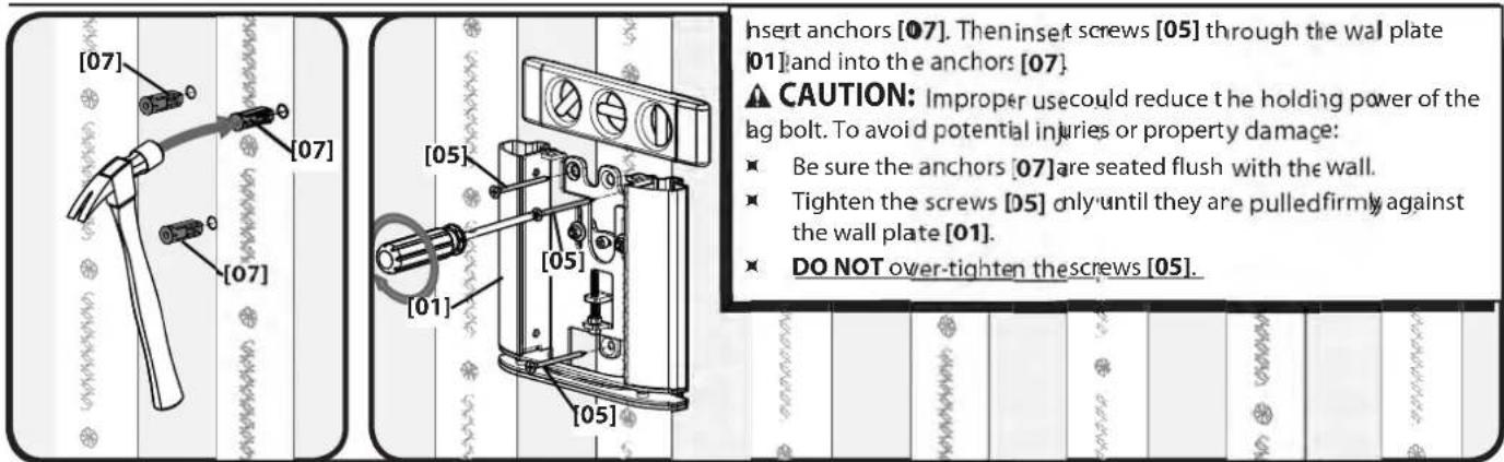
[07] [07] [07] [05] [01] [05] [05] Insert anchors [07]. Then insert screws [05] through the wall plate [01] and into the anchors [07]. ▲ CAUTION: Improper use could reduce the holding power of the bag bolt. To avoid potential injuries or property damage: ■ Be sure the anchors [07] are seated flush with the wall. ■ Tighten the screws [05] only until they are pulled firmly against the wall plate [01]. ■ DO NOT over-tighten the screws [05].3-1 Attach glass shelf
text_image
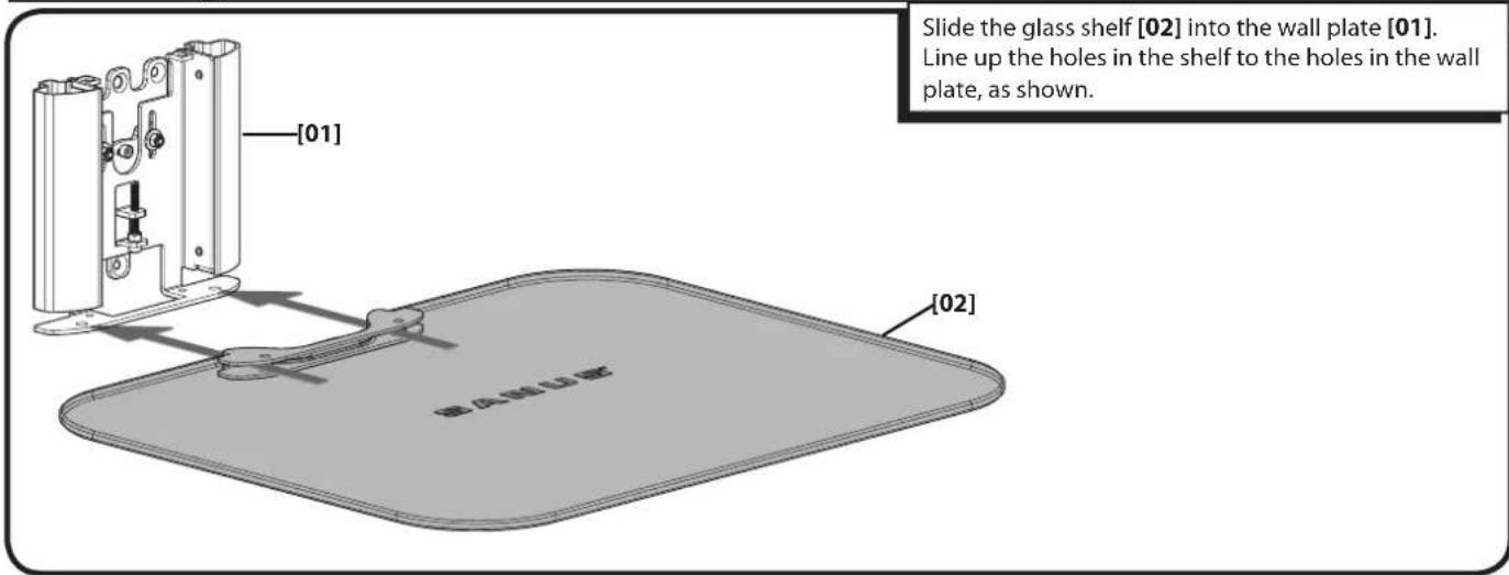
Slide the glass shelf [02] into the wall plate [01]. Line up the holes in the shelf to the holes in the wall plate, as shown. [01] [02]3-2 Secure glass shelf
text_image
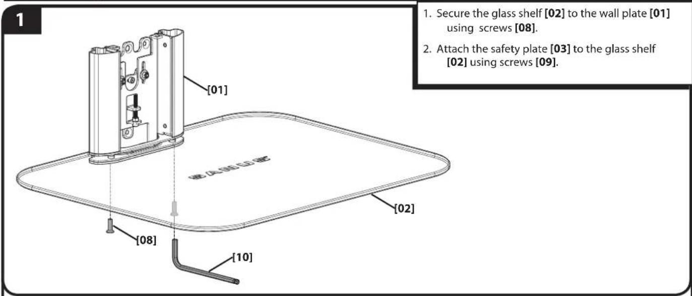
1 1. Secure the glass shelf [02] to the wall plate [01] using screws [08]. 2. Attach the safety plate [03] to the glass shelf [02] using screws [09]. [01] 硬(夹)面(LD)硬 [02] [08] [10]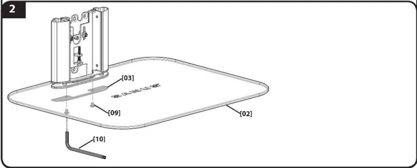
text_image
[03] [09] [10] [02]4 Manage Cables
4-1 Single shelf configurations
text_image
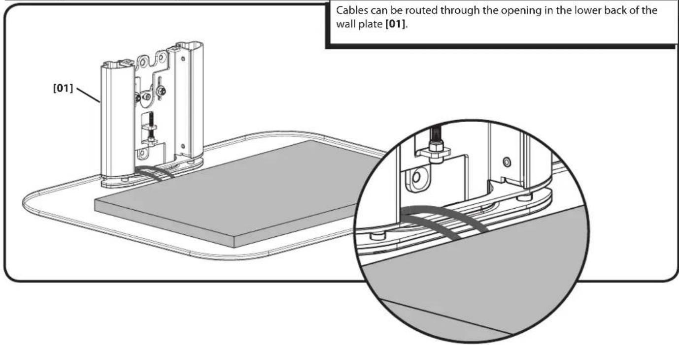
Cables can be routed through the opening in the lower back of the wall plate [01]. [01]4-2 Stacked confi gurations
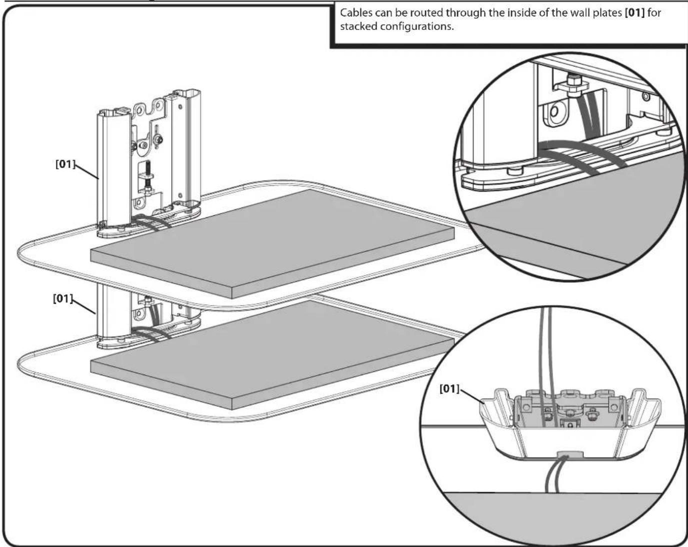
text_image
Cables can be routed through the inside of the wall plates [01] for stacked configurations. [01] [01] [01]5 Adjustments
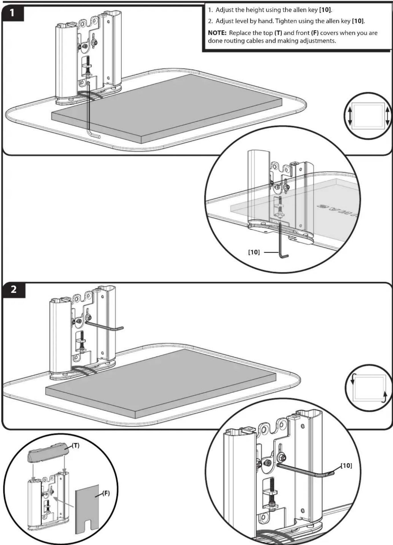
Français
CONSIGNES DE SÉCURITÉ IMPORTANTES – CONSERVEZ CES INSTRUCTIONS – VEUILLEZ LIRE ATTENTIVEMENT LE MANUEL AVANT D'UTILISER CE PRODUIT
Milestone AV Technologies and its affiliated corporations and subsidiaries (collectively, "Milestone"), intend to make this manual accurate and complete. However, Milestone makes no claim that the information contained herein covers all details, conditions, or variations. Nor does it provide for every possible contingency in connection with the installation or use of this product. The information contained in this document is subject to change without notice or obligation of any kind. Milestone makes no representation of warranty, expressed or implied, regarding the information contained herein. Milestone assumes no responsibility for accuracy, completeness or sufficiency of the information contained in this document.