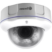
Pro-981 - Surveillance Camera SWANN - Free user manual and instructions
Find the device manual for free Pro-981 SWANN in PDF.


| Product Type | Surveillance Camera |
| Brand | Swann |
| Model | Pro-981 |
| Night Vision | Up to 30 m (100 ft) in total darkness |
| Lens | 4x optical zoom (2.8 mm - 12 mm), variable focal length |
| Field of View | Adjustable from 23° to 81° |
| Power Supply | AC adapter included |
| Video Connectivity | BNC (composite) |
| OSD Connectivity | RS485 (optional) |
| Mounting | Ceiling or wall, screw-mounted |
| Weather Protection | Weatherproof (foam gasket) |
| Warranty | 1 year |
| Maintenance | Clean the lens with a specialized lens cloth |
| Included Accessories | Screws, anchors, star-shaped tool |
| Weight | Approximately 500 g (estimate) |
| Dimensions | Approximately 15 cm (diameter) x 10 cm (height) |
Frequently Asked Questions - Pro-981 SWANN
User questions about Pro-981 SWANN
0 question about this device. Answer the ones you know or ask your own.
Ask a new question about this device
Download the instructions for your Surveillance Camera in PDF format for free! Find your manual Pro-981 - SWANN and take your electronic device back in hand. On this page are published all the documents necessary for the use of your device. Pro-981 by SWANN.
USER MANUAL Pro-981 SWANN
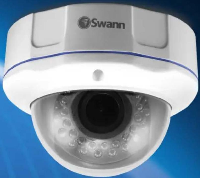
Ultimate Optical Zoom Dome Camera
Dome / Dôme / Domo
EN INSTRUCTION MANUAL
Congratulations on your purchase of this PRO-CAM from Swann! You've chosen well; we think this is one of the finest vari-focal CCTV video cameras available. The adjustable lens and on-screen menu system make the PRO-CAM ideal for monitoring any kind of space in almost any lighting conditions... even no light at all, as it can see up to 30m/100ft in complete darkness!
Our two cents: you've spent the money on a great camera. It's worth spending a bit of time making sure it's set up right. This manual will take you through what you need to do to get the camera delivering high quality images, and will let you know a little about how you can tweak it further.
The Process: An Overview
- Choose a spot for your camera. This will be influenced by what you need to monitor, the places nearby which could support a camera, the lighting conditions of the environment and so on (see section Mounting the Camera).
- Connect the camera to a monitor. We suggest connecting it directly to a monitor during setup, and to your DVR (or other recording device) afterwards. Having a monitor on hand in the same location as the camera is a real time saver during setup.
- Set the zoom. This will set the viewing angle of the lens, which determines how much the camera can view (see section Adjusting Zoom and Focus).
- Set the focus. This will allow you to choose which parts of what the camera can view is in focus (see section Adjusting Zoom and Focus).
- Connect the camera to your DVR or other recording/monitoring device (see section Connection Guide).
- Problem viewing images from your camera? Have a look at some of the solutions in the Troubleshooting section to troubleshoot and fix the problem. Technical support for your camera is also available to you via telephone and e-mail (see section Technical Support Details).
Choosing a Location
The PRO-CAM is very flexible, and can be installed practically anywhere. Some of the things you'll have to consider when choosing a location are:
- What you want to monitor, and where you'll get the best view of it.
- How you're going to connect the camera to your monitoring system.
- How to keep the camera out of harm's way. Up high in protected corners is a good option.
Mounting the Camera
To mount the camera, use the supplied mounting hardware (screws). If you're mounting onto a wooden surface, you can drive the screws directly into the wood. You may need to drill guide holes first, particularly if mounting the camera onto hardwood. If mounting on masonry or similar surface, use the included wall plugs.
The camera mounts to a flat surface, such as the underside of a ceiling or a sturdy wall.
- Using the included star-key tool, remove the dome cover.
-
Choose the most appropriate port to run the cable out of.
-
If you're going to run the cable into the roof or ceiling cavity, then prepare a hole in the ceiling which will line up with the hole in the top of the dome base. Use a high-quality sealant to ensure complete waterproofness.
-
If you're planning to run the cable on the exterior of the ceiling/wall, then undo the small protective cap on the side of the dome base and run the cable out that way. Note that this will reduce the weather resistance of the camera unless it is properly sealed with a high-quality sealant.
-
Attach the dome base to the ceiling using the included mounting screws, we recommend you put some silicone sealant under each screw head to prevent moisture entering the camera case.
- Aim the camera, and adjust the zoom and focus controls (see section Adjusting Zoom and Focus for details) to get the image that you want. It can be really helpful to have a television or monitor on hand so you can see what you're doing! Help from an able assistant never goes astray, either.
-
The dome cover only mounts one way – that is, the cable-out port on the side of the dome base means that the cover will only slide on when correctly oriented. If you've changed the default position of the camera, this may mean you'll need to re-orient the plastic dome cover.
-
On the underside of the dome cover there are two screws which are responsible for holding the plastic dome in place.
- Using a precision screwdriver, loosen the two small screws, and slide the tabs aside.
- Rotate the plastic component of the dome so that the transparent window lines up with the orientation of the camera.
- Re-orient the tabs and tighten the screws to hold the plastic dome in place.
- Re-attach the dome cover. When re-attaching the dome cover, ensure the foam ring that is fitted around the lens is tight against the inside of the clear plastic dome and that the spring is correctly in place. This will isolate the camera lens from the infrared LEDs and help cut down the light reflecting into the lens. It is very important that you do this; otherwise you may not get a clear picture during night vision. If you see bright spots in the picture, remove the dome cover and adjust the foam ring accordingly.
- Secure in place by tightening the screws.
Adjusting Zoom and Focus
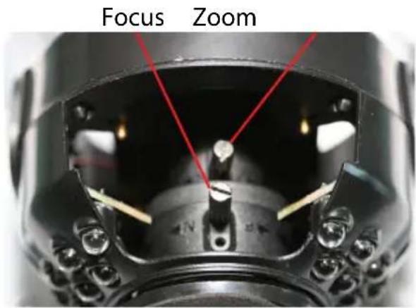
The zoom and focus controls are located on the interior of the dome, just above the lens. You'll need to remove the cover of the dome (using the included star-key tool) to access them and then use a small flat-blade screwdriver to turn the zoom and focus control rods.
Important: When you change the zoom, you'll also have to change the focus.
Why? Lenses are complicated, and all the bits are joined together. Changing the zoom will also change the focus. In fact, it can sometimes feel like the controls are reversed, so profound are their effect on one another.
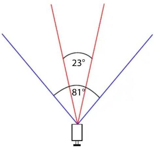
ZOOM: The rear lever (when viewed from the front of the lens, as shown on the right) controls the level of zoom. Twist the lever anti-clockwise a little to release the lens and then you can vary the viewing angle between 23° and 81°. This is an approximately 4x (2.8mm-12mm) optical zoom, which operates in a similar manner to the zoom on your digital camera. Basically, zooming in makes everything appear to be larger, at the expense of the width of the viewing area.
Check out the diagram to the lower right for a visual representation of the zooming process.
The smaller viewing angle (marked 23° ) represents the camera's view when "zoomed in", and the larger angle ( 81° ) represents the camera's view when "zoomed out".
You can set the zoom to either of these extremities, or anywhere in between.
Once you have adjusted the camera to your desired setting, twist the zoom lever gently clockwise until it is firm to stop the lens moving.
When the camera lens is fully extended (i.e., zoomed out), it's perfectly normal for vignetting to occur to some degree. Vignetting is a technical term in photography to describe the darkening of corners in the image that
you're seeing. To avoid the vignetting effect, increase the zoom of the lens by a small increment. This also means your camera will have a slightly reduced viewing angle.
Adjusting Zoom and Focus
FOCUS: The front lever controls the focus (see diagram, opposite).
Adjusting the focus control is kind of like trying on a different pair of glasses - it can make sharp things look blurry and blurry things look sharp. It's not quite magic, but it's pretty close.
Basically, once you've set the zoom, twist the focus lever anti-clockwise to loosen the lens and move the focus lever until what you want to see doesn't look blurry anymore. If you can't turn the knob any more one way, go back the other way.
You can only have so much in focus at once - photographers refer to the size of the area in focus as the “depth of field”.
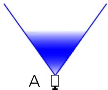
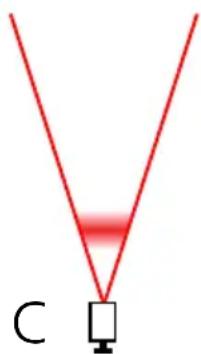
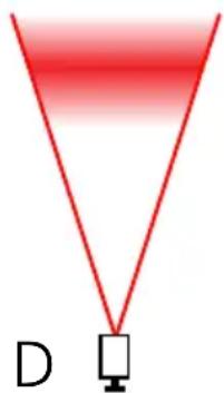
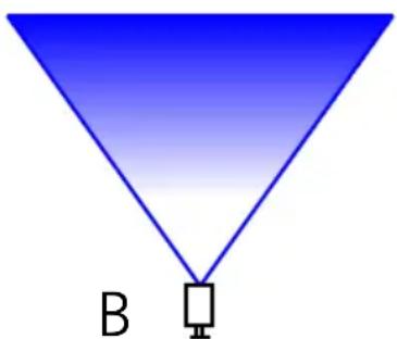
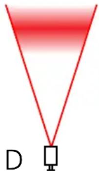
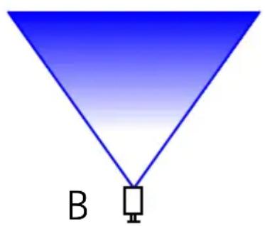
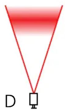
The diagram to the lower right shows a couple of different focusing options. The shaded areas represent the depth of field. As you can see, there is no hard edge, some things are “more” in focus than others.
Note that this is for illustrative purposes only - there are many factors which contribute to depth of field which vary from location to location.
Once you have adjusted the camera to your desired setting, twist the lever gently clockwise until it is firm to stop the lens moving.
Note: At the extremes of zoom (in or out) you may not be able to fully focus the image due to allowances in the lens mechanism, if this happens simply move the zoom back the other way a tiny amount to bring the image into clear focus.
A: The lens is at its widest, and focused on an area relatively close to the camera. The depth of field is quite large.
B: The lens at its widest with focus set to "infinity". Anything in the shaded section will be in focus, and this focus extends to infinity (that is, things in the far distance will also be in focus). However, things in the distance might be too small to see the detail you require.
C: The lens at its tightest, focused on an area close to the camera. As you can see, the more the lens is zoomed, the smaller the depth of field becomes.
D: The lens at its tightest with focus further from the camera. At this distance, the actual depth of field is much larger, but it doesn't extend to infinity like it does when the lens is wide.

Connection Guide
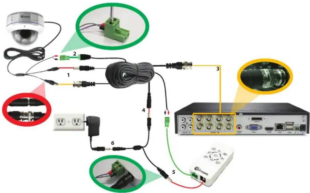
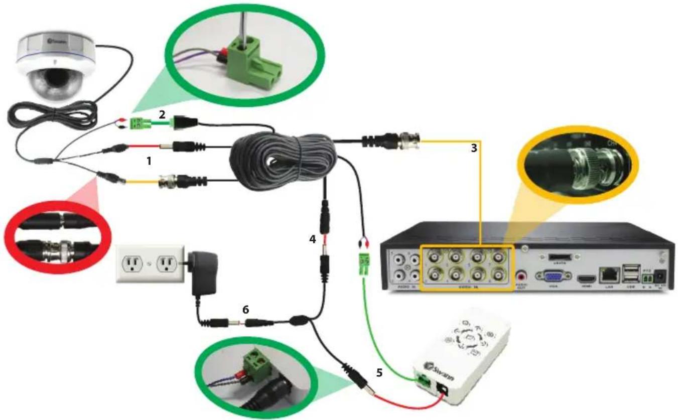
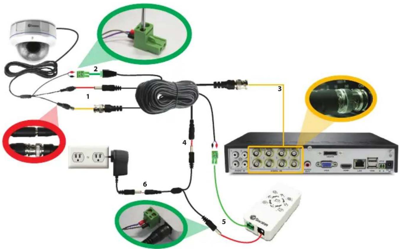
- Connect the camera's DC and BNC cables to the extension cable, twist the BNC connector to lock it together securely.
- (Optional) If you intend to use the OSD controller, connect the camera's green RS485 plug to the extension cable. You may first need to attach the RS485 plug to the wires on the cables as shown in the diagram above.
- Connect the other end of the BNC extension cable to an unused channel on the back of your DVR and twist the connector to lock it on securely.
- Connect the extension cable's DC socket to one end of the power splitter cable.
- (Optional) To use the OSD controller, plug the extension cable's RS485 plug (note red connector to A/+ and black connector to B/- on the controller socket) and the other end of the power splitter to the OSD controller's RS485 port and DC in power jack.
- Connect the power splitter cable to the power adapter, and plug the power adapter into a wall outlet.
Note: Once the camera is set up and working well it is a good idea to wrap some electrical tape around the connections between the camera cable and the BNC extension cable to keep moisture out and preserve the electrical integrity of the connection.
Troubleshooting
Problem: At night, all I see is white.
Solution: The camera is most likely looking through a window. At night, the infrared light the camera uses to see in the dark can 'bounce back' off a reflective surface (such as glass, water, spider webs, some ceramics and so on) and effectively blind the camera. If you want to see outside, mount the camera outside - we made it weatherproof for a reason!
Problem: I see only a blank screen where my image should be.
Solution: Check the wiring to the camera, and ensure the camera is being supplied power from the included power adapter. Try using a different video lead, or connecting the camera to a different television or monitor. Be sure there are no devices interrupting your signal, such as a DVR or VCR that isn't outputting the signal correctly.
Problem: I can't see anything at night.
Solution: The maximum range of the night vision is just that, the maximum range. If there's nothing in this range, you won't see anything. Also, some dark objects (like the proverbial black cat) may not reflect enough light to be seen except as a silhouette if the background is brighter. Some objects which can easily be seen in visible light don't reflect much infrared light.
Problem: Everything looks blurry/soft.
Solution: You probably need to adjust the focus (the knob on the right). This is simply a matter of removing the dome cover, and turning the control knob one way until you find the best focus point or it won't turn any more. Detailed instructions for setting the focus are described in the Adjusting Zoom and Focus section. Then, turn it back the other way. If there is no “sweet spot” then this indicates that you might be trying to focus on something outside the “depth of field” - objects need to be at least a certain distance from the camera for you to be able to focus on them. Typically, this will be only a few feet (about 1m) but this distance can increase dramatically if the lens is zoomed in, or in low light conditions. Be sure to replace the dome cover securely once you've set the focus!
Advanced Feature: On Screen Display (OSD)
The OSD is an optional use, advanced feature that allows you to change settings for:
Wide Dynamic Range (reduces the difference between light and dark areas of a scene)
3D Noise Reduction (reduces digital image "noise" in low light images)
Back Light Compensation (adjusts the image if strong light source is in the scene background)
Auto White Balance (another way of adjusting the image to compensate for different lighting and colour conditions in a camera scene)
Numerous other image tuning and camera setting options.
The camera will work perfectly well if you never attach the OSD controller - it will regulate all its settings automatically and will suit most applications.
The OSD controls are many and varied so if you would like to make some changes or have a particular need for your camera that requires some fine tuning, simply read the OSD guide included in your pack or you can download the guide to the OSD from our website:
www.swann.com/osdpro
Helpdesk / Technical Support Details
Swann Technical Support
All Countries E-mail: tech@swann.com
Telephone Helpdesk
USA toll free
1-800-627-2799
AUSTRALIA toll free
1300 138 324
USA Exchange & Repairs
1-800-627-2799 (Option 1)
(M-F, 9am-5pm US PT)
NEW ZEALAND toll free
0800 479 266
UK
0203 027 0979
Limited Warranty Terms & Conditions
Swann Communications warrants this product against defects in workmanship and material for a period of one (1) year from it's original purchase date. You must present your receipt as proof of date of purchase for warranty validation. Any unit which proves defective during the stated period will be repaired without charge for parts or labour or replaced at the sole discretion of Swann. The end user is responsible for all freight charges incurred to send the product to Swann's repair centres. The end user is responsible for all shipping costs incurred when shipping from and to any country other than the country of origin.
The warranty does not cover any incidental, accidental or consequential damages arising from the use of or the inability to use this product. Any costs associated with the fitting or removal of this product by a tradesman or other person or any other costs associated with its use are the responsibility of the end user. This warranty applies to the original purchaser of the product only and is not transferable to any third party. Unauthorized end user or third party modifications to any component or evidence of misuse or abuse of the device will render all warranties void.
By law some countries do not allow limitations on certain exclusions in this warranty. Where applicable by local laws, regulations and legal rights will take precedence.
For Australia: Our goods come with guarantees which cannot be excluded under Australian Consumer Law. You are entitled to a replacement or refund for a major failure and for compensation for any other reasonably foreseeable loss or damage. You are also entitled to have the goods repaired or replaced if the goods fail to be of acceptable quality and the failure does not amount to major failure.
FCC Verification
This equipment has been tested and found to comply with the limits for Class B digital device, pursuant to part 15 of the FCC Rules. These limits are designed to provide reasonable protection against harmful interference in a residential installation. This equipment generates, uses and can radiate radio frequency energy and, if not installed and used in accordance with the instructions, may cause harmful interference to radio or television reception, which can be determined by turning the equipment off and on, the user is encouraged to try to correct the interference by one or more of the following measures:
Reorient or relocate the receiving antenna
Increase the separation between the equipment and the receiver
- Connect the equipment into an outlet on a circuit different from that to which the receiver is connected
- Consult the dealer or an experienced radio/TV technician for help
WARNING: Modifications not approved by the party responsible for compliance could void user's authority to operate the equipment.
Sobre la cámara
Guía de Conexión
Guide de Connexion
Europe eusupport@swannsecurity. com
- ULTIMATE OPTICAL ZOOM DOME CAMERA
- THE PROCESS: AN OVERVIEW
- CHOOSING A LOCATION
- MOUNTING THE CAMERA
- ADJUSTING ZOOM AND FOCUS
- CONNECTION GUIDE
- TROUBLESHOOTING
- ADVANCED FEATURE: ON SCREEN DISPLAY (OSD)
- HELPDESK / TECHNICAL SUPPORT DETAILS
- SWANN TECHNICAL SUPPORT
- TELEPHONE HELPDESK
- USA EXCHANGE & REPAIRS
- NEW ZEALAND TOLL FREE
- LIMITED WARRANTY TERMS & CONDITIONS
- FCC VERIFICATION
- SOBRE LA CÁMARA
- GUÍA DE CONEXIÓN
- GUIDE DE CONNEXION
Brand : SWANN
Model : Pro-981
Category : Surveillance Camera