Pavilion LC3700N - TV HP - Free user manual and instructions
Find the device manual for free Pavilion LC3700N HP in PDF.

| Product Type | High-definition LCD TV (HDTV) |
| Brand | HP |
| Model | Pavilion LC3700N |
| Screen Size | 37 inches (94 cm) diagonal |
| Dimensions with stand and speakers (W x D x H) | 118.1 x 30.5 x 64.8 cm |
| Weight with stand and speakers | 27 kg |
| Power Supply | 120 V AC, 60 Hz |
| Power Consumption | 195 W (max) |
| Display Resolution | 1366 x 768 pixels (WXGA) |
| Connectivity | HDMI, DVI-I, i.LINK (2 ports), component inputs, S-video, composite, optical digital audio output, CableCARD, RS-232C |
| Main Features | Built-in digital and analog tuning, cable-ready for digital cable with CableCARD, Dolby Virtual Surround, backlit universal remote, optical picture control (OPC), V-Chip parental control |
| Care and Cleaning | Unplug before cleaning. Use a soft, lint-free cloth slightly dampened with water. Do not use solvents, alcohol, or abrasive products. |
| Safety | Follow instructions: do not expose to water, do not block ventilation, use only on a stable surface, refer all servicing to qualified personnel. |
| Spare Parts and Repairability | The TV contains no user-serviceable parts. Contact a qualified technician for any repairs or part replacement. |
| General Information | Warranty: 1 year parts and labor. Manufactured under license from Dolby, BBE, HDMI. Contains mercury in the LCD lamp – recycling required at end of life. |
Frequently Asked Questions - Pavilion LC3700N HP
User questions about Pavilion LC3700N HP
0 question about this device. Answer the ones you know or ask your own.
Ask a new question about this device
Download the instructions for your TV in PDF format for free! Find your manual Pavilion LC3700N - HP and take your electronic device back in hand. On this page are published all the documents necessary for the use of your device. Pavilion LC3700N by HP.
USER MANUAL Pavilion LC3700N HP
HP Pavilion LCD HDTV User's Guide
HP Pavilion LC3700N 37-Inch (94-Centimeter) LCD High-Definition Television
HP Pavilion LC3200N 32-Inch (81-Centimeter) LCD High-Definition Television
HP Pavilion LC2600N 26-Inch (66-Centimeter) LCD High-Definition Television

invent
The only warranties for HP products and services are set forth in the express warranty statements accompanying such products and services. Nothing herein should be construed as constituting an additional warranty. HP shall not be liable for technical or editorial errors or omissions contained herein.
HP assumes no responsibility for the use or reliability of its software on equipment that is not furnished by HP.
This document contains proprietary information that is protected by copyright. No part of this document may be photocopied, reproduced, or translated to another language without the prior written consent of HP.
Hewlett-Packard Company
P.O. Box 4010
Cupertino, CA 95015-4010
USA
Copyright © 2005 Hewlett-Packard Development Company, L.P.
Manufactured under license from Dolby Laboratories. Dolby, Pro Logic, and the double-D symbol are trademarks of Dolby Laboratories.
Manufactured under license from BBE Sound, Inc. Licensed by BBE Sound, Inc. under USP4638258, 5510752 and 5736897. BBE and BBE symbol are registered trademarks of BBE Sound, Inc.
HDMI, the HDMI logo and High-Definition Multimedia Interface are trademarks or registered trademarks of HDMI Licensing LLC.
CableCARD™ is a trademark of Cable Television Laboratories, Inc.
i.LINK and the i.LINK logo are registered trademarks of Sony Electronics, Inc.
This product incorporates copyright protection technology that is protected by method claims of certain U.S. patents and other intellectual property rights owned by Macrovision Corporation and other rights owners. Use of this copyright protection technology must be authorized by Macrovision Corporation, and is intended for home and other limited viewing uses only unless otherwise authorized by Macrovision Corporation. Reverse engineering or disassembly is prohibited. Apparatus Claims of U.S. Patent Nos. 4,631,603, 4,577,216, 4,819,098, 4,907,093, 5,315,448, 6,381,747, and 6,516,132.
This digital television is capable of receiving analog basic, digital basic and digital premium cable television programming by direct connection to a cable system providing such programming. A security card provided by your cable operator is required to view encrypted digital programming. Certain advanced and interactive digital cable services such as video-on-demand, a cable operator's enhanced program guide and data-enhanced television services may require the use of a set-top box. For more information call your local cable operator.
HP supports lawful use of technology and does not endorse or encourage the use of our products for purposes other than those permitted by copyright law.
The information in this document is subject to change without notice.

Text set off in this manner indicates information you need.

Text set off in this manner indicates important information you need.

CAUTION: Text set off in this manner indicates that failure to follow directions could result in damage to equipment or loss of information.

WARNING: This symbol is intended to alert the user to the presence of important operating and maintenance (servicing) instructions in the literature accompanying the appliance.

DANGEROUS VOLTAGE: Text set off in this manner indicates the presence of uninsulated voltages within the product enclosure that may be of sufficient magnitude to constitute a risk of electrical shock to persons.
Important Safeguards
WARNING: TO REDUCE THE RISK OF FIRE OR ELECTRICAL SHOCK, DO NOT EXPOSE THIS APPLIANCE TO RAIN OR MOISTURE.

CAUTION: RISK OF ELECTRICAL SHOCK ⚠️! DO NOT OPEN
CAUTION: TO REDUCE THE RISK OF ELECTRICAL SHOCK, DO NOT REMOVE COVER (OR BACK). NO USER SERVICEABLE PARTS INSIDE. REFER SERVICING TO QUALIFIED SERVICE PERSONNEL.

THIS SYMBOL IS INTENDED TO ALERT THE USER TO THE PRESENCE OF UNINSULATED "DANGEROUS VOLTAGES" WITHIN THE PRODUCT'S ENCLOSURE THAT MAY BE OF SUFFICIENT MAGNITUDE TO CONSTITUTE A RISK OF ELECTRICAL SHOCK TO PERSONS. REFER SERVICING TO QUALIFIED SERVICE PERSONNEL.

THIS SYMBOL IS INTENDED TO ALERT THE USER TO THE PRESENCE OF IMPORTANT OPERATING AND MAINTENANCE (SERVICING) INSTRUCTIONS IN THE LITERATURE ACCOMPANYING THE APPLIANCE.
CAUTION: TO PREVENT ELECTRICAL SHOCK, DO NOT USE THIS POLARIZED AC PLUG WITH AN EXTENSION CORD, RECEPTACLE, OR OTHER OUTLET UNLESS THE BLADES CAN BE FULLY INSERTED TO PREVENT BLADE EXPOSURE.
CAUTION: TO PREVENT ELECTRICAL SHOCK, MATCH WIDE BLADE OR PLUG TO WIDE SLOT, FULLY INSERT.
CAUTION: DO NOT PLACE THIS PRODUCT ON AN UNSTABLE CART, STAND, TRIPOD, BRACKET, OR TABLE. THE PRODUCT MAY FALL CAUSING SERIOUS PERSONAL INJURY AND SERIOUS DAMAGE TO THE PRODUCT. USE ONLY WITH A CART, STAND, TRIPOD, BRACKET, OR TABLE RECOMMENDED BY THE MANUFACTURER OR SOLD WITH THE PRODUCT. FOLLOW THE MANUFACTURER'S INSTRUCTIONS WHEN INSTALLING THE PRODUCT AND USE MOUNTING ACCESSORIES RECOMMENDED BY THE MANUFACTURER. A PRODUCT AND CART COMBINATION SHOULD BE MOVED WITH CARE. QUICK STOPS, EXCESSIVE FORCE, AND UNEVEN SURFACES MAY CAUSE THE PRODUCT AND CART COMBINATION TO OVERTURN.

WARNING: FCC Regulations state that any unauthorized changes or modifications to this equipment not expressly approved by the manufacturer could void the user's authority to operate this equipment.
CAUTION: This product satisfies FCC regulations when shielded cables and connectors are used to connect the unit to other equipment. To prevent electromagnetic interference with electric appliances such as radios and televisions, use shielded cables and connectors for connections.
INFORMATION:
This equipment has been tested and found to comply with the limits for a Class B digital device, pursuant to Part 15 of the FCC Rules. These limits are designed to provide reasonable protection against harmful interference in a residential installation. This equipment generates, uses, and can radiate radio frequency energy and, if not installed and used in accordance with the instructions, may cause harmful interference to radio communications. However, there is no guarantee that interference will not occur in a particular installation. If this equipment does cause harmful interference to radio or television reception, which can be determined by turning the equipment off and on, the user is encouraged to try to correct the interference by one or more of the following measures:
■Reorient or relocate the receiving antenna.
■Increase the separation between the equipment and receiver.
■ Connect the equipment into an outlet on a circuit different from that to which the receiver is connected.
■Consult the dealer or an experienced radio/TV technician for help.
RESPONSIBLE PARTY:
Hewlett-Packard Company
Digital TV Solutions
Attn: Product Regulations Manager
10435 N. Tantau Avenue
CAC 07, MS 4295
Cupertino, CA 95014 USA
Important Safety Instructions
Electricity is used to perform many useful functions, but it can also cause personal injuries and property damage if improperly handled. This product has been engineered and manufactured with the highest priority on safety. However, improper use can result in electric shock and/or fire. In order to prevent potential danger, please observe the following instructions when installing, operating, and cleaning the product. To ensure your safety and prolong the service life of your Liquid Crystal Television, please read the following precautions carefully before using the product.
1 Read these instructions.
2 Keep these instructions.
3 Heed all warnings.
4 Follow all instructions.
5 Do not use this apparatus near water.
6 Clean only with dry cloth.
7 Do not block any ventilation openings. Install in accordance with the manufacturer's instructions.
8 Do not install near any heat sources such as radiators, heat registers, stoves, or other apparatus (including amplifiers) that produce heat.
9 Do not defeat the safety purpose of the polarized or grounding-type plug. A polarized plug has two blades with one wider than the other. A grounding-type plug has two blades and a third grounding prong. The wide blade or the third prong are provided for your safety. If the provided plug does not fit into your outlet, consult an electrician for replacement of the obsolete outlet.
10 Protect the power cord from being walked on or pinched particularly at plugs, convenience receptacles, and the point where they exit from the apparatus.
11 Only use attachments/accessories specified by the manufacturer.
12 Use only with the cart, stand, tripod, bracket, or table specified by the manufacturer, or sold with the apparatus. When a cart is used, use caution when moving the cart/apparatus combination to avoid injury from tip-over.

13 Unplug this apparatus during lightning storms or when unused for long periods of time.
14 Refer all servicing to qualified service personnel. Servicing is required when the apparatus has been damaged in any way, the power-supply cord or plug is damaged, liquid has been spilled or objects have fallen into the apparatus, the apparatus has been exposed to rain or moisture, does not operate normally, or has been dropped.
15 Power Sources — This product should be operated only from the type of power source indicated on the marking label. If you are not sure of the type of power supply to your home, consult your product dealer or local power company. For products intended to operate from battery power, or other sources, refer to the operating instructions.
16 Overloading — Do not overload wall outlets, extension cords, or integral convenience receptacles as this can result in a risk of fire or electric shock.
17 Object and Liquid Entry — Never push objects of any kind into this product through openings as they may touch dangerous voltage points or short-out parts that could result in a fire or electric shock. Never spill liquid of any kind on the product.
18 Damage Requiring Service — Unplug this product from the wall outlet and refer servicing to qualified service personnel under the following conditions:
a When the AC cord or plug is damaged,
b If liquid has been spilled, or objects have fallen into the product,
c If the product has been exposed to rain or water,
d If the product does not operate normally by following the operating instructions. Adjust only those controls that are covered by the operating instructions as an improper adjustment of other controls may result in damage and will often require extensive work by a qualified technician to restore the product to its normal operation,
e If the product has been dropped or damaged in any way, and
f When the product exhibits a distinct change in performance – this indicates a need for service.
19 Replacement Parts — When replacement parts are required, be sure the service technician has used replacement parts specified by the manufacturer or have the same characteristics as the original part. Unauthorized substitutions may result in fire, electric shock, or other hazards.
20 Safety Check — Upon completion of any service or repairs to this product, ask the service technician to perform safety checks to determine that the product is in proper operating condition.
21 The apparatus shall not be exposed to dripping or splashing and that no objects filled with liquids, such as vases, shall be placed on apparatus.
22 WARNING: Plug the power cord into a power outlet where access to the power cord connector is readily accessible in case power disconnection is required.
23 Servicing: The user should not attempt to service the appliance beyond that described in the operating instructions. All other servicing should be referred to qualified service personnel.
■ Water and Moisture — Do not use this product near water; for example, near a bath tub, wash bowl, kitchen sink, or laundry tub; in a wet basement; or near a swimming pool; and the like.
■ Stand — Do not place the product on an unstable cart, stand, tripod, or table. Placing the product on an unstable base can cause the product to fall, resulting in serious personal injuries as well as damage to the product. Use only a cart, stand, tripod, bracket, or table recommended by the manufacturer or sold with the product.
■ Selecting the location — Select a place with no direct sunlight and good ventilation.
■ Ventilation — The vents and other openings in the cabinet are designed for ventilation. Do not cover or block these vents and openings since insufficient ventilation can cause overheating and/or shorten the life of the product. Do not place the product on a bed, sofa, rug, or other similar surface, since they can block ventilation openings. This product is not designed for built-in installation; do not place the product in an enclosed place such as a bookcase or rack, unless proper ventilation is provided or the manufacturer's instructions are followed.
■ The Liquid Crystal panel used in this product is made of glass. Therefore, it can break when the product is dropped or applied with impact. Be careful not to be injured by broken glass pieces in case the panel breaks.
■ Heat — The product should be situated away from heat sources such as fireplaces, chimneys, radiators, heat registers, stoves, or other products (including amplifiers) that produce heat.
■ The Liquid Crystal panel is a very high technology product with 3,147,264 thin film transistors, giving you fine picture details.
Occasionally, a few non-active pixels may appear on the screen as a fixed point of blue, green, or red. Please note that this does not affect the performance of your product.
■Cautions regarding use in high and low temperature environments:
When the unit is used in low-temperature space (e.g., room, office), the picture may leave trails or appear slightly delayed. This is not a malfunction, and the unit will recover when the temperature returns to normal.
Do not leave the unit in a hot or cold location. Also, do not leave the unit in a location exposed to direct sunlight or near a heater, as this may cause the cabinet to deform and the Liquid Crystal panel to malfunction. Storage temperature: -4^ F to +140^ F ( -20^ C to +60^ C)
■ Precautions when transporting the TV — When transporting the TV, never carry it by holding onto the speaker. Be sure to always carry the TV by two people holding it with two hands — one hand on each side of the Display.
■ Lightning — For added protection for this television equipment during a lightning storm, or when it is left unattended and unused for long periods of time, unplug it from the wall outlet and disconnect the antenna. This will prevent damage to the equipment due to lightning and power-line surges.
■ Power Lines — An outside antenna system should not be located in the vicinity of overhead power lines or other electric light or power circuits, or where it can fall into such power lines or circuits. When installing an outside antenna system, extreme care should be taken to keep from touching such power lines or circuits as contact with them might be fatal.
■Outdoor Antenna Grounding — If an outside antenna is connected to the television equipment, be sure the antenna system is grounded so as to provide some protection against voltage surges and built-up static charges. Article 810 of the National Electrical Code, ANSI/NFPA 70, provides information with regard to proper grounding of the mast and supporting structure, grounding of the lead-in wire to an antenna discharge unit, size of grounding conductors, location of antenna-discharge unit, connection to grounding electrodes, and requirements for the grounding electrode.
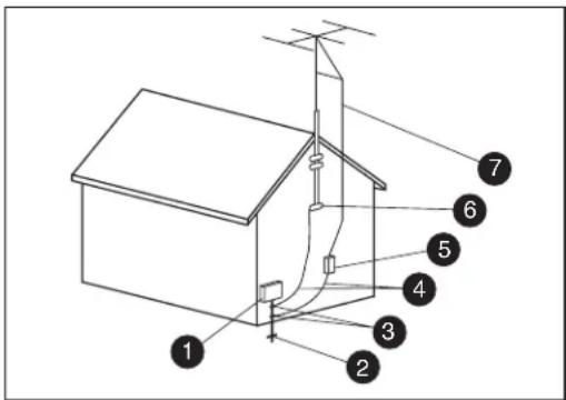
Antenna Grounding
Antenna Grounding
| Reference | Grounding Component |
| 1 | Electric Service Equipment |
| 2 | Power Service Grounding Electrode System (NEC Art 250, Part H) |
| 3 | Ground Clamps |
| 4 | Grounding Conductors (NEC Section 810-21) |
| 5 | Antenna Discharge Unit (NEC Section 810-20) |
| 6 | Ground Clamp |
| 7 | Antenna Lead in Wire |
■ To prevent fire, never place any type of candle or flames on the top or near the TV set.
■ To prevent fire or shock hazard, do not expose this product to dripping or splashing. No objects filled with liquids, such as vases, should be placed on the product.
■ To prevent fire or shock hazard, do not place the AC power cord under the TV set or other heavy items.
■ Turn off the main power and unplug the AC cord from the wall outlet before handling.
■ Use a soft cloth and gently wipe the surface of the TV panel. Using a hard cloth may scratch the panel surface.
■ Use a soft damp cloth to gently wipe the panel when it is really dirty. (It may scratch the panel surface when wiped strongly.)
■ If the panel is dusty, use an anti-static brush, which is commercially available, to clean it.
■ To protect the panel, do not use a dirty cloth, liquid cleaners, or chemical cloth to clean it; such materials may damage the panel surface.
■ Do not display a still picture for a long time, as this could cause an afterimage to remain.
Important Information
The TV must be serviced by an authorized service technician. The TV is not user serviceable.
Changes can damage your TV and void your warranty. Changes or modifications not expressly approved by the manufacturer could void the user's authority to operate the equipment.
Your TV supports use of a CableCARD, provided by your cable company, when using a direct digital connection to a cable system providing encrypted digital programming. Note that some interactive or on-demand services may still require use of a set-top box provided by the cable company. For more information, contact your cable company.
Recycling Information
For information about how to recycle this product through HP, see:
http://www.hp.com/recycle
Other recycling options may also be available in your area. If located within the U.S. and Canada, you may also call (1) (888) 485-1849.
Materials disposal
This HP product contains the following materials that might require special handling at end-of-life:
■Mercury in the fluorescent lamp in the LCD.
Disposal of mercury may be regulated because of environmental considerations. For disposal or recycling information, please contact your local authorities or the Electronic Industries Alliance (EIA)
(http://www.eia.org).
Cleaning precautions
Unplug the TV before cleaning the screen.
A special antiglare coating is applied to the screen of your TV. Using solvents, such as alcohol, or abrasive material, such as a premoistened or chemically treated towel, may affect the screen coating or bezel paint.
Do not expose the product to volatile gas or fluid such as a pesticide.
Do not put the TV in contact with vinyl or rubber products for a long period of time. Extended contact may result in the removal of the coating or degradation of the surface.
Lifting precautions
The TV is heavy; be sure to use ergonomically correct lifting procedures when moving the TV.
Due to the size and weight of the TV, it is recommended that a minimum of two people move it.
For transport, grasp the display in the area under and above the screen.
If speakers are attached to the display, do not lift the display by the speakers; instead, use the area under and above the screen.
Never place the display with the glass screen facing downward, unless it is protected with pads.
Table of Contents
Important Safeguards...... iii
Important Safety Instructions......iv
Important Information ......viii
Getting to Know Your TV...... 1
Identifying Items in the Box ....1
Locating TV Buttons and Connectors.... 2
Cleaning 6
Cleaning precautions 6
Cleaning the TV....6
Setting Up....7
Selecting a Good Location....7
Unpacking....7
Lifting the TV 8
Removing or attaching the stand.... 8
Setting Up the TV....10
Attaching and connecting the display speakers .... 10
Connecting the TV signal sources....11
Connecting the cable TV or the air broadcast antenna.... 12
Using a CableCARD 13
Connecting cable or satellite with a set-top box ....15
Connecting a DVD player, VCR, DVR, game console, or camcorder....17
Connecting a VCR for recording.... 23
Connecting a PC 23
Connecting an external sound system.... 24
Connecting power to the TV.... 25
Turning On the TV 27
Turning the TV On and Off (Standby).... 27
Using the First-Time Setup Wizard. 29
Initial Setup.... 29
Using the Remote Control ......31
Operating the TV or the Selected Device....31
Installing or replacing remote control batteries....31
Identifying the remote control buttons....32
Adjusting the Volume 34
Muting the sound 34
Changing Channels 35
Selecting the last channel....35
Operating a DVD or other device 35
Displaying program information....35
Selecting the Input Source....35
Changing the View with the Aspect Button .....35
Turning On Captions....36
Setting SAP/MTS stereo mode....36
Turning On Dolby Virtual 36
Setting the Sleep Timer 36
Adjusting TV Settings....36
Opening and exiting the OSD 36
Operating an i.LINK device ....37
About i.LINK 37
Setting the recording mode (i.LINK)....37
Setting the standby mode (i.LINK) ......37
Selecting an i.LINK device ....38
Disabling the TV's operation of an i.LINK device ....38
Deleting registered i.LINK devices....39
Controlling an i.LINK device....39
Automatic input switching to i.LINK ....41
Recording digital programs with a D-VHS deck (i.LINK) 42
Recording digital programs with an
AV-HDD recorder or Blu-ray Disc recorder....42
Playing back using Rec List (i.LINK) 43
Selecting a Device to Control.... 43
Programming the remote control for a home entertainment device 44
Programming the device code.... 44
Searching for the device code.... 44
HP MCPC and HP DEC PCs.... 54
Changing the TV Settings......55
Using the OSD Menus.... 55
Using the Picture Menu.... 55
Adjusting the picture settings.... 56
Using the Audio Menu 57
Adjusting the audio....57
Using the Power Control Menu.... 58
Adjusting Power Control for an AV video source.... 58
Adjusting Power Control for a PC source ..... 58
Using the Setup Menu.... 58
Starting EZ Setup.... 59
Using CH Setup....59
Using Antenna Setup - Digital.... 59
Using Parental CTRL....60
Setting Position.... 60
Using Input Signal 60
Using Auto Sync.... 60
Using Fine Sync.... 60
Setting Input Label 61
Setting Picture Flip 61
Setting Standby Mode.... 61
Setting Language.... 61
Using the Options Menu.... 61
Using the Digital Setup Menu.... 62
Using the CableCARD Menu.... 62
Using the Video Setup.... 62
Using Audio Setup.... 63
Using the i.LINK Setup.... 63
Viewing TV Identification information 63
Selecting the view aspect.... 63
Using Closed Caption 64
Using Parental Controls 65
Secret number setting for parental control (AV input mode only) 65
Setting Parental Control V-Chip level ......66
How to temporarily release the V-Chip BLOCK....69
Reactivating the temporarily released V-Chip BLOCK....69
Returning to Factory Presets....69
Finding Answers to Questions ..... 71
Understanding TV Terms....71
What are Analog TV, Digital TV, and high-definition (HDTV)?......71
What is the difference between progressive and interlaced signal formats for digital TVs? ....71
What is variable aspect ratio?......71
What is HDMI?......71
What is CableCARD, and how does it work? 72
Identifying Cable Usage 72
Specifications.... 75
PC Compatibility Chart....77
RS-232C Port Specifications....78 PC control of the TV....78
Troubleshooting 79
FCC Notice 83
Federal Communications Commission Notice....83
Modifications ....83 Cables....83
Recording your secret number 83
Getting to Know Your TV
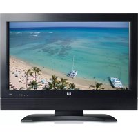
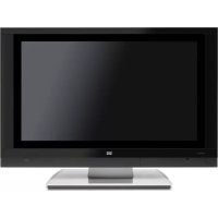
Thank you for purchasing an HP Pavilion LCD High-definition Television. The HP Pavilion LCD HDTV is designed to deliver a fantastic image for an immersive home theater experience.
Features:
■Premium LCD panel technology delivers up to 800:1 contrast for rich detail, fast response time for no-smear motion video, and ultrawide viewing angles with a minimum of color shift.
■Built-in digital and analog tuning receives and decodes HDTV, digital, and analog broadcasts received from off-air antennas and cable providers.
■Digital cable readiness enables use of an authorized CableCARD (certain countries/regions only) to receive digital cable television systems services directly from the cable operator without requiring a separate cable box. (Contact your local cable company for information regarding acquiring CableCARD.)
■HDMI interface offers pure digital video and audio quality through a lossless digital interface to DVD players, cable and satellite receivers, and AV receivers.
■Dual i.LINK interfaces offer bi-directional digital video, audio, and control of digital VHS players and audio/visual hard disk drive (AV HDD).
■Dolby Digital 5.1 channel optical digital output enables a full home theater sound experience when attached to an external Dolby Digital decoder and a multi-channel amplifier.
■Dolby Virtual Surround delivers a compelling virtual surround sound experience.
■Illuminated universal remote control works with additional components, including HP Media Center PC and HP Digital Entertainment Centers.
Identifying Items in the Box
 | Television |
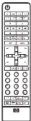 | Remote control unit |
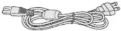 | AC cord |
 | Cable clamp (select models only) |
 | Cable tie |
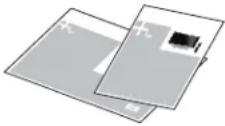 | Documentation |
 | Display speakers with mounting hardware (most models have speakers attached) |
Locating TV Buttons and Connectors
The TV contains controls, tuners, connectors, and the CableCARD slot.
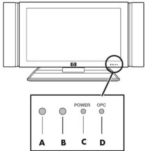
The TV indicators are located on the front of the TV, and the controls are located on the top.
Front TV
| Item TV Front item Description | ||
| A OPC | sensor Optical Picture Control (OPC) senses the surrounding light and automatically adjusts the backlight brightness. Make sure no object obstructs the OPC sensor, which could affect its ability to sense surrounding light. | |
| B Remote control sensor Location where to point the remote control unit. | ||
| C Power indicator Shows whether the TV is on or off/standby. Light is blue when turned on, and is off when TV is in off/standby mode. | ||
| D | OPC indicator | Indicates that the OPC is on. For information on the OPC, refer to “Turning On the TV” on page 27. |
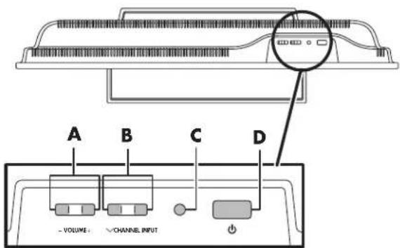
Top TV controls
2 HP Pavilion LCD HDTV User's Guide
| Item TV Top Control Description | ||
| A Left arrow and right arrow buttons (volume) | Press the left arrow button to lower the sound, and press the right arrow to raise the sound. | |
| B Down | arrow and up arrow buttons (channel) | Press the up and down buttons to select the next lower or higher channel. |
| C Input button Selects an LCD TV input source. | ||
| D Power | button Turns on the TV | or places it in standby mode. |
Rear TV connectors
The connectors are located on the side of the TV. They are located in sections by the following types of connections: tuners (digital and analog inputs), S-video, component, and AV inputs (Inputs 1, 2, 3), i.LINK, CableCARD, RS-232, DVI (Input 5), HDMI (Input 4), and power.
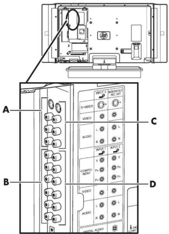
| Item TV (Rear) Description | ||
| A S-video or Video, with Audio left and right (Input 3) | Connect an S-video cable and left-right audio cables from optional equipment.Or, connect composite video and left-right audio cables.Audio connectors are shared. | |
| B Component Video or Video with Audio left and right (Input 1) | Connect Component Video cables and left-right audio cables from optional equipment.Supports standard inputs 480i, 480p, 720p, and 1080i. The TV automatically determines what has been connected. Some set-top boxes must be set for a specific resolution out.Or, connect composite video and left-right audio cables.Audio connectors are shared. | |
| C Monitor | Out/Rec Out terminals | Output for monitoring or recording video. Connect an S-video cable and left-right audio cables. Or, connect composite video and left-right audio cables. Audio connectors are shared. |
| D Component | Video or Video with Audio left and right (Input 2) | Identical to Input 1. |
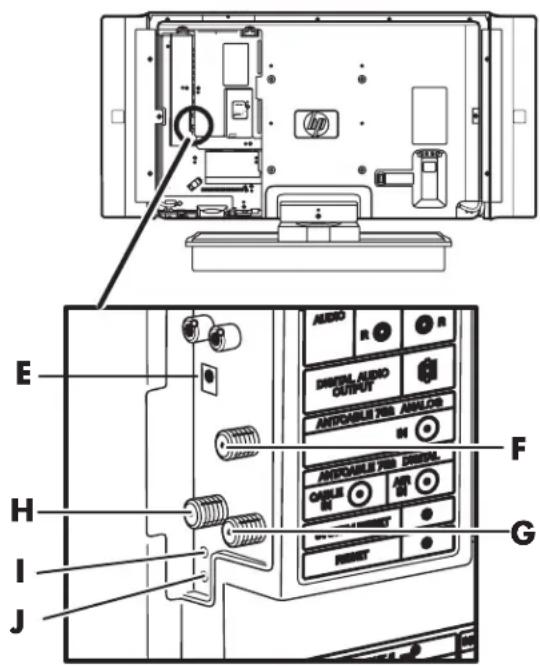
| Item TV (Rear) Description | ||
| E Digital | Audio Output | Optical connection for external audio system. |
| F Analog | Air/Cable TV In | Connect an analog air TV or analog cable. |
| G Digital | Air TV In | Connect a digital air TV antenna cable. |
| H Digital | Cable TV In | Connect a digital cable TV signal cable. |
| I System | Reset | Press if TV does not operate after starting up. |
| J Reset | Press if TV cannot return to its original state after performing an option. | |
Press Reset (J) if the TV cannot return to its original state after performing various operations; the resulting values are:
■AV Mode resets to Dynamic (fixed)
■TV channel returns to initial channel (Air: channel 2, Cable: channel 1 or 2)
■Audio setting initializes
■Dolby Virtual resets to off
■Image position initializes
Press System Reset (I) if the TV does not operate after starting up.

■ Pressing Reset will not work if the TV is in standby mode.
- Pressing Reset will not delete channel preset or secret number. See "Secret number setting for parental control (AV input mode only)" on page 65. See "Returning to Factory Presets" on page 69 for initializing to the factory preset values when you forget your secret number.
Rear TV connectors (continued)
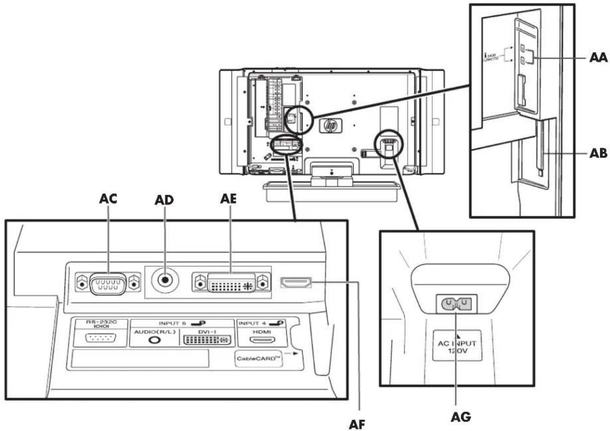
| Item TV (Rear) Description | ||
| AA i.LINK Connect a 4-pin i.LINK cable | from optional digital equipment in your home theater system. | |
| AB Cable | eCARD (certain countries/regions only) | Insert a cable company-provided card to receive standard definition or high-definition programs instead of using a separate set-top box. |
| AC RS-2 | 32 Terminal Used for industrial | control applications. |
| AE/AD | Input 5 terminal (DVI-I with audio) | Connect a PC using DVI video and audio (3.5 mm stereo mini-jack). Can connect VGA by using an RGB-to-DVI conversion cable or adapter. |
| AF High | Definition Multimedia Interface (HDMI) Input (Input 4) | Connect an HDMI cable for digital, high-definition optional equipment. |
| AG | AC in (power) cord | Connect the included power cord. Note: Use only the provided power cord. |
Cleaning
Cleaning precautions
Unplug the TV before cleaning the screen.
A special antiglare coating is applied to the screen of your TV. Using solvents, such as alcohol, or abrasive material, such as a premoistened or chemically treated towel, may affect the screen coating or bezel paint.
Do not expose the product to volatile gas or fluid such as a pesticide.
Do not put the TV in contact with vinyl or rubber products for a long period of time. Extended contact may result in the removal of the coating or degradation of the surface.
Cleaning the TV
Clean the screen by spraying a soft lint free cloth with water to lightly moisten it. Gently wipe the screen and avoid pressing on the screen.
To clean the outer cabinet, use the same method.
Do not use liquid or aerosol cleaners.
Setting Up
HP recommends professional installation from an authorized installer to ensure maximum enjoyment of your HP Pavilion LCD HDTV. Be sure to read all the safety information and precautions before starting installation. See these topics:
■"Important Safeguards" on page iii
■"Important Safety Instructions" on page iv
■"Important Information" on page viii
Selecting a Good Location
Select the location for your HP Pavilion LCD HDTV. To position the TV, consider:
■Power cord length: Choose a location with easy access to an AC power outlet.
■Cable lengths and distances to attached units: Check that cables can reach the TV.
■Do not install the TV on an unstable cart or stand; the unit may fall over and cause injury.
■Do not install the TV where it has a protruding edge, such as on a small table where the display overhangs the table surface.
■Do not hang the TV from the ceiling; the unit may fall and cause injury.
■Avoid direct sunlight that may damage the display or interfere with the operation of the remote control.
■Avoid areas of high humidity or damp conditions that may cause fire or electrical shock.
■Do not install TV near appliances, such as a microwave, or near a heat source, such as a fireplace or radiator.
■Provide adequate ventilation clearance around the TV.
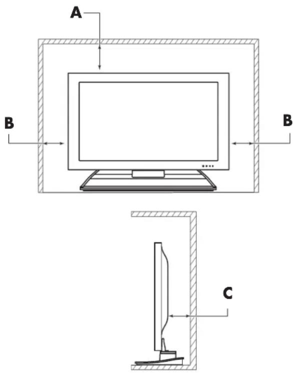
A 1.4 in (3.5 cm) minimum above TV
B 1.4 in (3.5 cm) minimum at sides
C 1.4 in (3.5 cm) minimum behind TV
Unpacking
Be sure to read through "Lifting the display" for important information.
Unpack the TV and put it on a stable surface:
1 Use the cardboard holders on either side of the TV to remove it from the box.
2 Remove the cardboard; however, keep the wrapping on the TV to protect it while moving.
3 Lift the TV onto the installation location.
Lifting the TV
The TV is heavy; be sure to use ergonomically correct lifting procedures when moving the TV.
Due to the size and weight of the TV, it is recommended that a minimum of two people move it.
To transport the TV, grasp the display in the area under and above the screen.
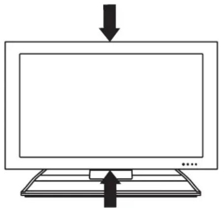
natural_image
Simple line drawing of a monitor with an arrow pointing to the front panel (no text or symbols)If speakers are attached to the TV, do not lift the TV by the speakers; instead, use the area under and above the screen.
Move the product gently. Never place the TV with the glass screen facing downward, unless it is protected with pads.
Removing or attaching the stand
Your TV comes with a stand already attached to the display.
Removing the stand
Before removing the stand, unplug the AC cord from the AC input terminal.
1 Place a pad or foam (A) on a stable table.
2 Carefully place the TV with the glass screen facing downward on the pad. Position it with the stand hanging over the edge of the table; hold the stand in place.

WARNING: The stand is heavy. Do not drop the stand.
3 Proceed with the steps for your type TV stand:
■For a paddle-type stand, continue with step 4.
■For a pedestal-cover stand, continue with step 5.
4 For the TV with a paddle-type stand, hold the stand in place and remove the four screws that secure the stand to the TV. Lift the stand off the TV. This completes stand removal for this type of stand.
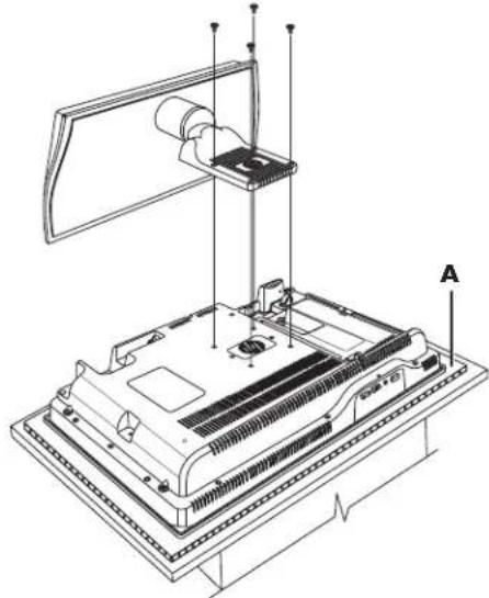
natural_image
Technical line drawing of a computer monitor with labeled components (no text or symbols present)A: Pad protecting TV with paddle-type stand
5 For the TV with a pedestal-cover stand, remove the retaining screw from the stand pedestal cover (B in next figure). Remove the cover.
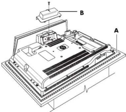
A: Pad protecting TV with pedestal-cover stand
B: Pedestal cover
6 Four screws (D) secure the pedestal to the TV chassis in the mounting area. The tabs (C) in the mounting area form the slot for the pedestal leading edge. Remove the four screws (D), and then slide the pedestal straight out of the TV.
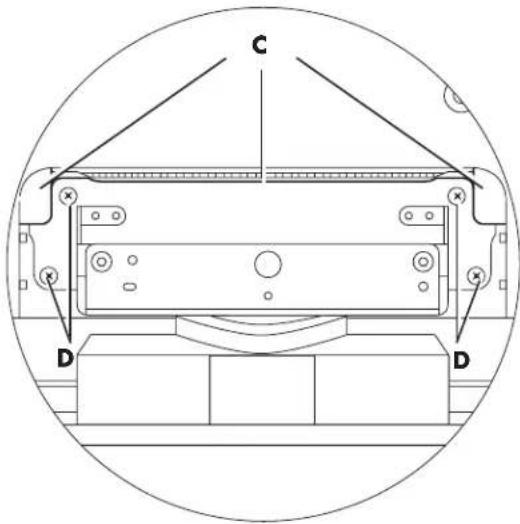
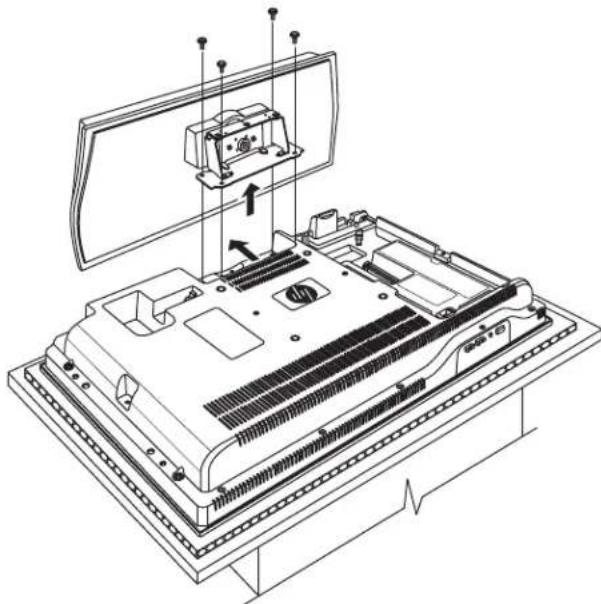
natural_image
Technical line drawing of an electronic device chassis with mounting bracket and internal components (no text or symbols)Installing the stand
Before attaching the stand, unplug the AC cord from the AC input terminal.
1 Carefully place the TV with the glass screen facing downward on a padded, stable table. Position the bottom of the TV near the edge of the table.
Refer to the figures in "Removing or attaching the stand" on page 8.

WARNING: The stand is heavy. Do not drop the stand onto the TV.
2 Proceed with the steps for your type TV stand:
■For a paddle-type stand, continue with step 3.
■ For a pedestal-cover stand, continue with step 5.
3 For the TV with a paddle-type stand, position the stand on the TV and align the four screw holes. (Refer to the figure in step 4 of the previous procedure.) Insert the four screws to secure the stand to the TV.
4 Carefully lift the TV and set it upright. This completes stand installation for this type stand.
5 For the TV with a pedestal-cover stand, the tabs (C) in the mounting area of the TV from the slot for the pedestal leading edge. (Refer to the figure in step 6 of the previous procedure.) Hold the stand with the front (thin) edge pointing down and the pedestal horizontal. Lower the stand onto the TV with the pedestal in the mounting area. Then, slide the stand forward until the leading edge is underneath the tabs (C) and the screw holes (D) align.
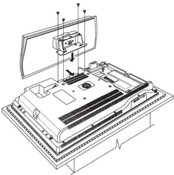
natural_image
Technical line drawing of an electronic device chassis with mounting bracket and internal components (no text or symbols)6 Insert the screws into the four holes (D).
7 Position the pedestal cover (B) over the pedestal, tip the cover to place the top edge into the mounting area, and then lower the cover onto the pedestal. (Refer to the figure in step 5 of the previous procedure.) Move the cover to align the cover with the screw hole, and insert the retaining screw.
8 Carefully lift the TV and set it upright. This completes stand installation for this type stand.
Setting Up the TV
Set up the TV by attaching and connecting the display speakers, connecting cables, and connecting the power cord. Some TV models come with speakers attached.
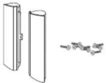
Attaching and connecting the display speakers
Speakers with speaker cables attach to each side of the display. The right speaker is located on the right side of the display when it is viewed from the front.
The TV has a digital audio output that you can connect to a separate external amplifier.
To use a separate external amplifier or a stereo system, refer to "Connecting an external sound system" on page 24.

CAUTION: Unplug power for the TV and all connected components before attaching or connecting speakers.
1 Position the TV display upright on its stand.
2 Place a speaker onto the TV display and insert the screws to secure it. Use the long screws for the top and bottom, and the short screw in the middle. Select models use only two screws.
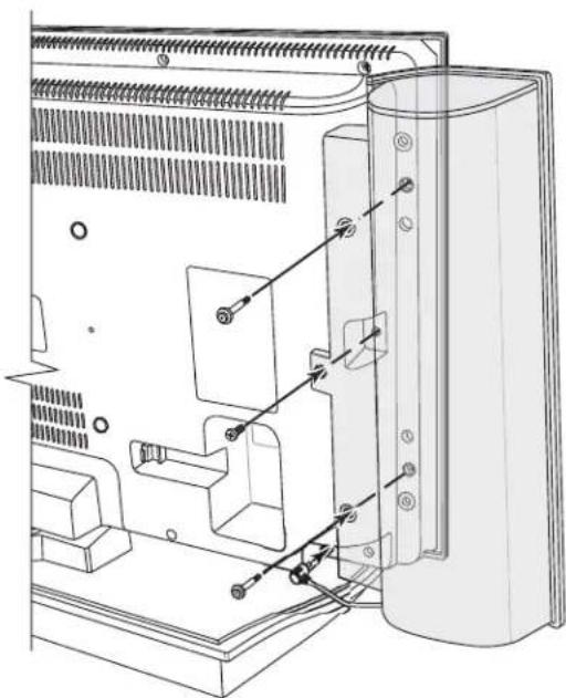
natural_image
Technical line drawing of an internal computer case with labeled components (no text or symbols)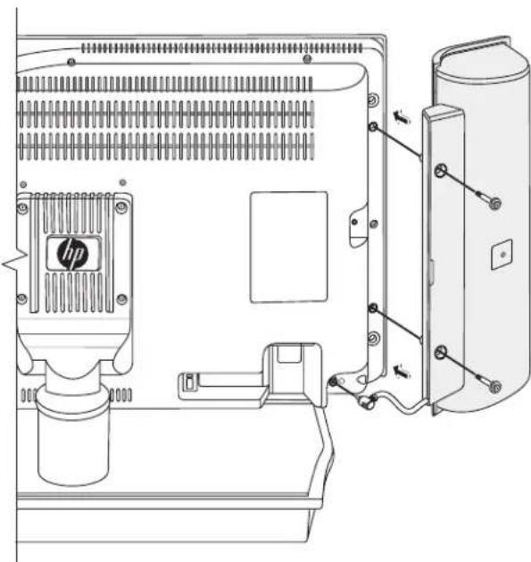
natural_image
Technical line drawing of a mechanical assembly with HP logo and housing (no text or symbols)3 Plug the speaker into the TV.
4 Repeat these steps for the other speaker.
Connecting the TV signal sources
The following is an explanation of the types of connections that are used for a coaxial cable. If your outdoor antenna uses a 75-ohm coaxial cable with an F-type connector, plug it into the antenna terminal at the rear of the TV set.
■A 75-ohm system is generally a round cable with an F-type connector that can easily be attached to a terminal without tools (sold separately).
■A 300-ohm system is a flat, twin-lead cable that can be attached to a 75-ohm terminal through a 300/75-ohm adapter (sold separately).

An F-type connector should be finger-tightened only. When connecting the RF cable to the TV set, do not use tools to tighten the F-type connector, as it may cause damage to your TV set.
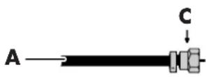

A: 75-ohm coaxial cable, round
B: 300-ohm twin-lead cable, flat
C: F-type connector
D: Use fingers to tighten F-type connector.
Connect the input sources to the TV according to the type of connection:
■ Antenna or basic cable (TV cable or satellite) without using a set-top box: see "Connecting the cable TV or the air broadcast antenna" on page 12.
■Cable with a CableCARD (U.S. only): see "Using a CableCARD" on page 13.
■Cable or satellite with a separate set-top box: see "Connecting cable or satellite with a set-top box" on page 15.

■To connect an external sound system, see "Connecting an external sound system" on page 24.
■To connect a device that records TV, use Terminal 3 (Monitor Out/Record Out) for a VCR or use the i.LINK Terminal. (Note that i.LINK records only digital programs.)
Connecting the cable TV or the air broadcast antenna
Use standard 75-ohm coaxial cable to connect a ground antenna or cable TV input source to the TV. Use shielded coaxial cable to reduce radio frequency (RF) interference.
Optional equipment, cable TV service, splitters, combiners, and all cables are sold separately.

CAUTION: Unplug power for the TV and all connected components before connecting the antenna or cable.
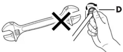
1 Connect the input source coaxial cable to the Analog Air In (A), Digital Air In (B), or Digital Cable In (C) connectors on the back of the TV.
■ For broadcast signals, you can use a combiner to add together your VHF antenna, UHF antenna, and digital antenna. Then, use a splitter (E) to connect the signal cable to both the Analog Air In and Digital Air In connectors (F) on the TV.
For cable without a CATV converter, use a combiner to add together your broadcast antenna signals (see previous bullet) and the cable signal. Then, use a splitter (E) to connect the signal cable to both the Analog Air In and Digital Air In connectors (F) on the TV.
■ For cable with a CATV converter, use a splitter (E) to connect the signal cable to both the Analog Air In and Digital Cable In connectors (H) on the TV.
You can use either Digital Cable In or Digital Air In, or use both. To view low numbered cable channels, be sure to connect your cable TV source to the Analog In connector.
A: Analog Air In connector
B: Digital Air In connector
C: Digital Cable In connector
D: Antenna (air analog or air digital signal source)
2 Connect power to the TV; see "Connecting power to the TV" on page 25.
Using a CableCARD
Use these steps when you have a CableCARD (certain countries/regions only) for premium digital cable service and you do not want to use a set-top box from the cable provider.
To use a digital set-top box, refer to "Connecting cable or satellite with a set-top box" on page 15.

If you change your address, return the CableCARD to your cable company. Obtain a new CableCARD from your new cable provider.
E: Splitter
F: Analog In and Digital Air In
G: Cable at wall (cable analog or cable digital signal source)
H: Analog In and Digital Cable In
3 Turn on the TV; see "Turning the TV On and Off (Standby)" on page 27.
!
Your TV supports use of a CableCARD, provided by the cable company, when using a direct digital connection to a cable system providing encrypted digital programming. Note that some interactive or on-demand services may still require use of a set-top box provided by the cable company. For more information, contact your cable company.
About Emergency Alert System (EAS)
In the case of a national emergency, natural disaster, or other emergency situation, an EAS message broadcasts. When this unit receives an EAS message, if the level of emergency is comparatively low, an alert text message displays on screen. If the level of emergency is high, the receiver is forced-tuned to a details channel.
■Alert text messages display, and forced tuning occurs, even during paid programming. Even when forced tuning is active, the user can still change the channel.
■If the unit is forced-tuned to a channel that has been blocked by Parental Control, the Parental Control setting is given priority, and the EAS message is not broadcast.
■If you have a digital cable antenna connected, you can receive EAS messages whether CableCARD is inserted or not.
■EAS messages may be broadcast not only through digital cable, but also through analog cable or over-the-air Analog transmission.
■When forced tuning occurs, video output from the Monitor Out terminal is also switched to the details channel.
■An alert text message does not output from Monitor Out terminal.
Connecting and initiating CableCARD
Optional equipment and all cables are sold separately.
1 Connect the cable TV input source using the Digital Cable In connector, as described in the previous procedure, "Connecting cable TV or the air broadcast antenna."
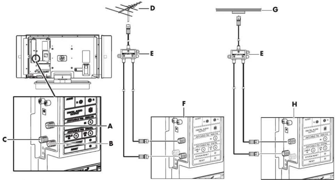
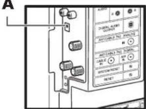
2 Remove the dust cover from the CableCard slot (AB).
AB: CableCARD slot with dust cover
3 With the TV on, insert the CableCARD provided by your cable company into the card slot (AB) on the back of the TV. Insert the card with the upper side facing right. Wait for the CableCARD message to appear; it may take several minutes to do so.

CAUTION: DO NOT remove the power cord while the CableCARD is inserted.
4 When the message appears, read it and contact your cable provider to enable the card.
Removing CableCARD
1 Turn on the TV; see "Turning the TV On and Off (Standby)" on page 27.
2 Check that the CableCARD upgrade screen is not displayed. If it is displayed, wait until it disappears.
3 Check that the OPC light on the front of the TV is NOT red; see "Turning the TV On and Off (Standby)" on page 27. If it is red, wait for the OPC light to change or go out.
4 Remove the CableCARD.
Disconnecting the cable antenna when using CableCARD
1 Turn on the TV; see "Turning the TV On and Off (Standby)" on page 27.
2 Check that the CableCARD upgrade screen is not displayed. If it is displayed, wait until it disappears.
3 Check that the OPC light on the front of the TV is NOT red. If it is, wait for it to change or go out.
4 Disconnect the cable antenna.
For more information about CableCARD, refer to "Using the CableCARD Menu" on page 62.
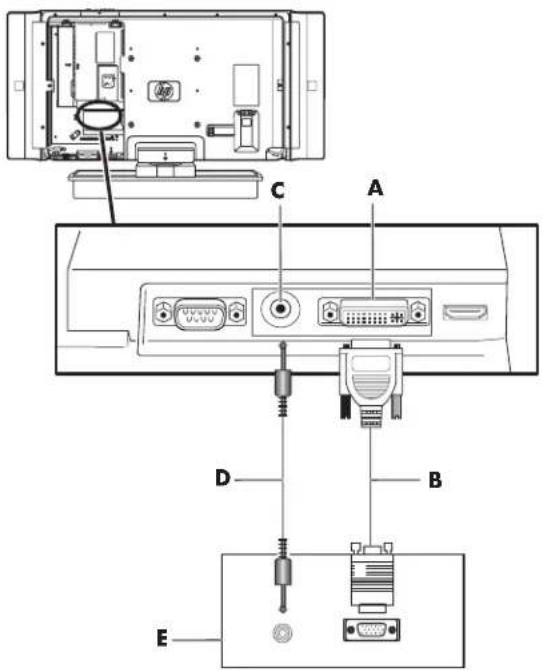
Connecting cable or satellite with a set-top box
Connecting your TV directly to the audio and video output of your set-top box assures a more vivid picture and enhances your viewing enjoyment.
Optional equipment and all cables are sold separately.
You can connect a digital TV set-top box (air or cable) and other audiovisual equipment by using:
■Input 1 terminals with either component or composite video connections
■Input 2 terminals with either component or composite video connections
■Input 4 terminals with HDMI connection
■Input 5 terminals with DVI connections

If your cable TV company has CableCARD available, you can also use the CableCARD to receive HDTV programs. See "Using a CableCARD" on page 13.

CAUTION: Unplug power for the TV and all connected components before connecting the set-top box.
1 Connect the set-top box input source cable(s) to the back of the TV using one of the terminals sets.
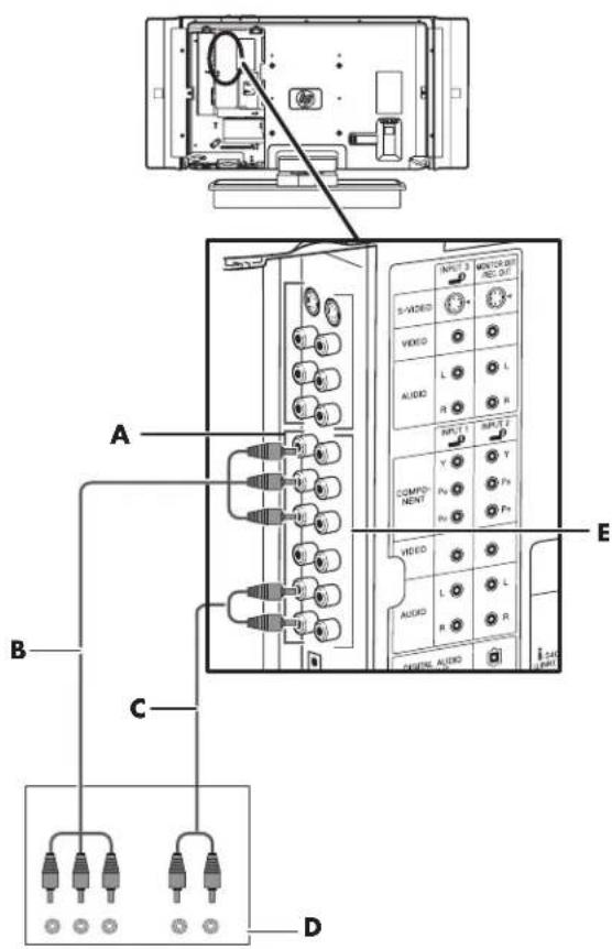
■ Input 1 (A) or Input 2 (E) using component connections. (Input 1 shown.)
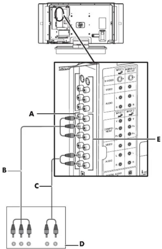
A: Input 1, with component, composite video, and audio connectors
B: Component video cable
C: Audio cable
D: Digital TV set-top box output connectors
E: Input 2, with component, composite video, and audio connectors
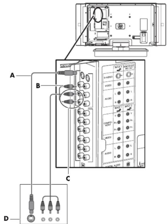
■ Input 1 (A) or Input 2 (D) using composite video connections. (Input 1 shown in figure.)
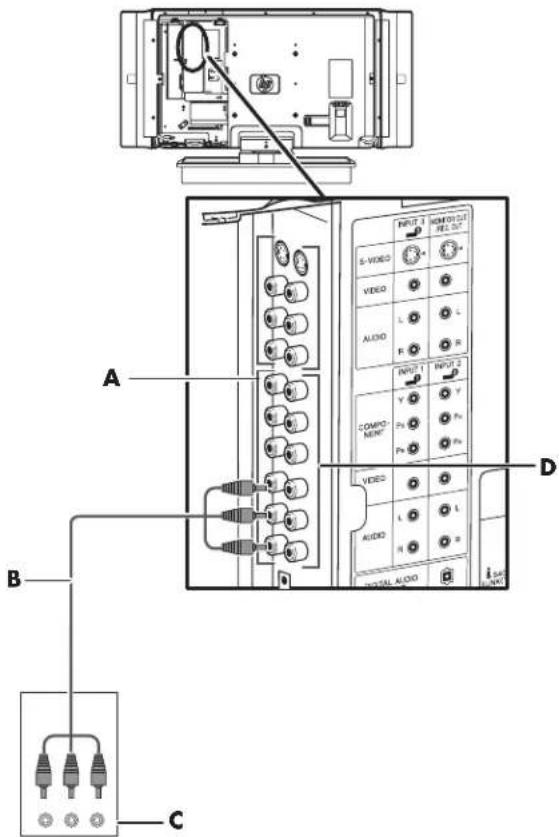
A: Input 1, with component, composite video, and audio connectors
B: Composite video cable with video and audio connectors
C: Digital TV set-top box output connectors
D: Input 2, with component, composite video, and audio connectors
■Input 4 using HDMI connection Refer to "Connecting an HDMI device" on page 18 for connecting a digital TV set-top box or other device using the HDMI terminal.
■Input 5 using DVI connections
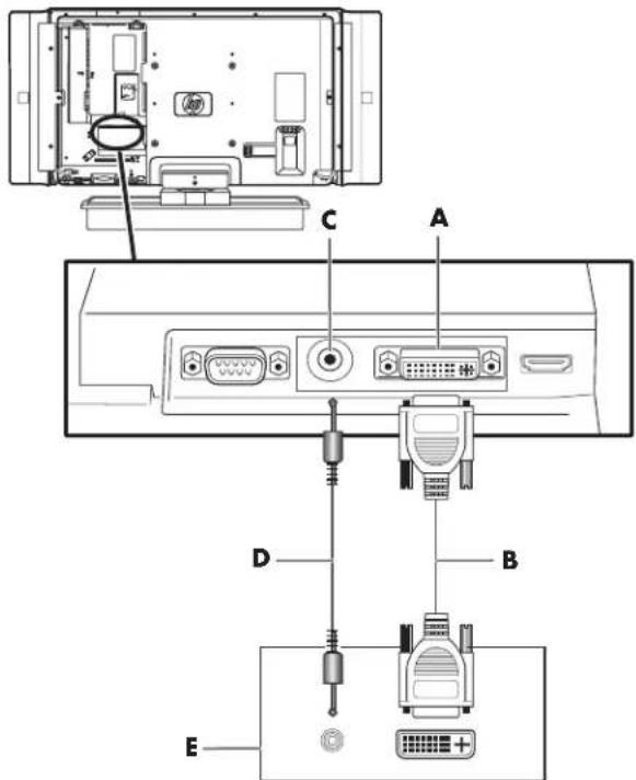
A: Input 5, with DVI-I video, and audio (C) connectors
B: DVI-I video cable
C: Input 5 audio connector
D: Audio cable
E: Digital TV set-top box output connectors
2 Connect the cables to the set-top box.
3 Turn on the set-top box.
4 Connect power to the TV (see page 25). Turn on the TV; see "Turning the TV On and Off (Standby)" on page 27.
5 Select the input source and scan for channels; see "Using the First-Time Setup Wizard" on page 29.
Connecting a DVD player, VCR, DVR, game console, or camcorder
You can connect optional equipment (sold separately), such as a DVD player, VCR, DVR, and so on, to the TV by using the AV input connectors.
Optional equipment, including an external sound system, and all cables are sold separately.
You can connect a DVD by using:
■Input 1 terminals with either component or composite video connections.
■Input 2 terminals with either component or composite video connections.
■Input 3 terminals with either S-video or composite video connections.
■Input 4 terminals with HDMI connection.
■Input 5 terminals with DVI connections.
You can connect a VCR by using Input 3 terminals with either S-video or composite video connections for playback, and by using Monitor Out/Rec Out terminals for recording (input to the VCR). See
"Connecting a VCR for recording" on page 23 to use the Monitor Out/Rec Out terminals.
You can connect a game console, camcorder, and some other AV equipment by using Input 3 terminals with either S-video or composite video connections.
You can connect HDMI equipment by using Input 4 terminal with an HDMI connection.
You can connect DVI equipment by using the Input 5 terminals with an DVI-I connection.
You can connect i.LINK equipment by using one of the i.LINK terminals.
Choosing the AV connection to use
When connecting optional equipment as signal sources, the connectors on the equipment may limit the type of connection you can use.
When your optional equipment has more than one type of output connector, choose the connection that provides the best quality play back image.
For best results, choose the best quality connection type that is supported by your optional equipment.
The following table lists the available optional AV equipment connections on the TV.
| AV connection to use, listed from best to good video playback | ||
| Connection Description TV Connector Cable Plug | ||
| HDMI transmits an all digital signal and is the recommended choice for playback from a digital DVD or DVR. |  | 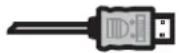 |
| DVI transmits an all digital video signal for playback from a digital DVD or DVR. | 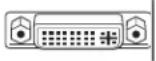 | 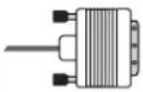 |
| i.LINK transmits an all digital signal. Multiple devices can be connected using an i.LINK connector. A device connected using i.LINK can be set up to record high-definition television. The TV has two S400 (4-pin) i.LINK connectors. See “Connecting an i.LINK device” on page 19. | 4-pin | 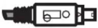 |
| AV connection to use, listed from best to good video playback (Continued) | ||
| Connection Description TV Connector Cable Plug | ||
| Component(Y, Pb, Pr) transmits video as separate red, green, and blue signals. Use this connection for high-definition video signals in 480i, 480p, 720p, or 1080i format from a progressive scan DVD or other equipment. |    | 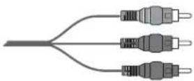 |
| S-video transmits video in separate color and black-and-white image signals and delivers a sharper image than a composite video connection. |  |  |
| AV In video(composite) transmits video as a single signal. |  | 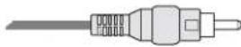 |
The procedures that follow, presented in the order listed in the table, describe connecting optional equipment including the audio connections when applicable.

CAUTION: Unplug power for the TV and all connected components before connecting optional equipment. Ensure that the optional equipment is powered off.
Connecting an HDMI device
This is the recommended connection for video and audio. The HDMI cable is sold separately.
1 Connect the HDMI cable to INPUT 4 (A). (There are no separate audio inputs for HDMI.)
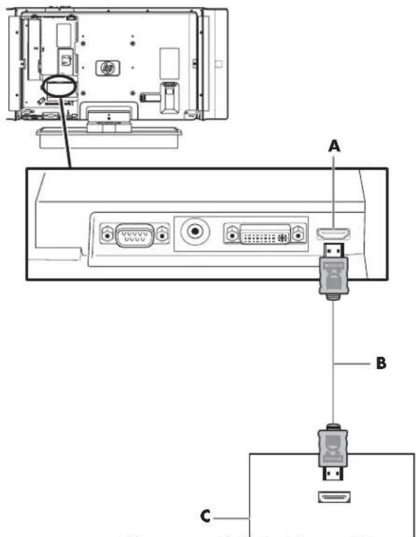
A: Input 4, with HDMI digital video with audio connector
B: HDMI cable
C: HDMI device output connectors
2 Connect the cable to the HDMI device (C).
3 Turn on the device, and start play.
4 Connect power to the TV (see page 25).
5 Turn on the TV; see "Turning the TV On and Off (Standby)" on page 27.
6 Select the input source by pressing the Input button on the remote control or on the TV.
7 Define the HDMI Setup items under Options in the Menu screen displays; refer to "Using the Options Menu" on page 61.
Connecting a DVI device
The DVI cable and the audio cable are sold separately.
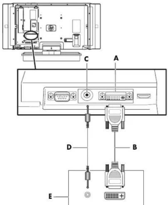
1 Connect the DVI-I cable (B) and an audio cable (D) to the Input 5 connectors.
2 Connect the cables to the DVI device (E).
3 Turn on the device, and start play.
4 Connect power to the TV (see page 25).
5 Turn on the TV; see "Turning the TV On and Off (Standby)" on page 27.
6 Select the input source by pressing the Input button on the remote control or on the TV.
7 Define the type of device connected to Input 5 (DVI) by using Input Select under Options in the Menu screen displays; refer to "Using the Options Menu" on page 61.
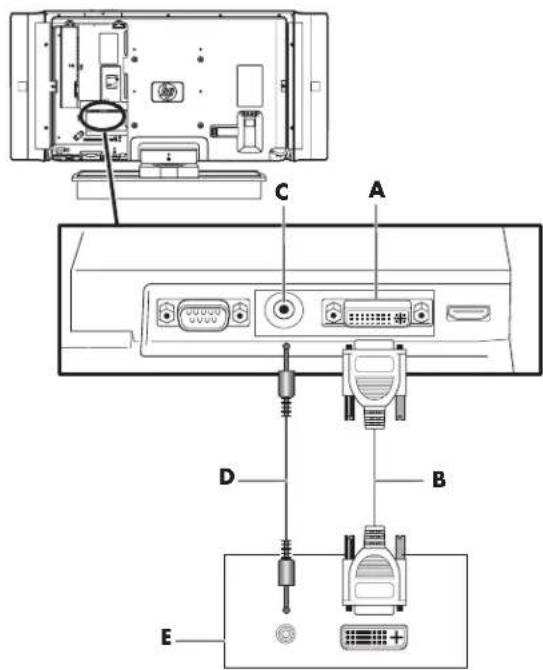
A: Input 5, with DVI-I video, and audio (C) connectors
B: DVI-I video cable
C: Input 5 audio connector
D: Audio cable
E: DVI device output connectors
Connecting an i.LINK device
This is an all-digital connection for video. The i.LINK cables are sold separately.
Only D-VHS decks, AV HDD recorders, and Blu-ray Disc recorders can be connected to this TV with i.LINK. Device recognition, control, recording, and playback operations may not be possible on some devices. Other devices such as DVD recorders, digital video cameras, PCs, or PC peripheral devices do not meet the specifications for this TV and cannot be connected with i.LINK.
Only digital programs can be recorded by an i.LINK devices connected to this TV using the i.LINK. (Analog broadcasts or external input signals from Input terminals 1 through 5 cannot be recorded by i.LINK.)
!
DO NOT connect a PC using i.LINK. Instead, refer to "Connecting a PC" on page 23.
Connecting two or more i.LINK devices
Up to 16 i.LINK devices can be connected using a daisy-chain connection with i.LINK cables.
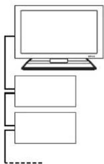
flowchart
graph TD
    A["Computer monitor"] --> B["Rectangle 1"]
    A --> C["Rectangle 2"]
    A --> D["Rectangle 3"]
    A -.-> E["Empty Line"]
When 3 or more i.LINK devices are connected, branch connection can be used. With branch connections, up to 62 i.LINK devices can be connected.
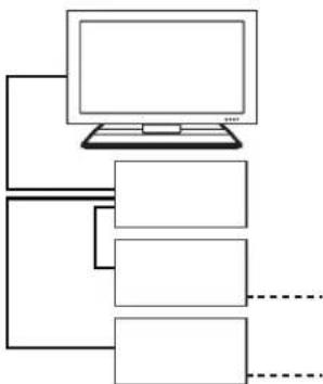
flowchart
graph TD
    A["Computer"] --> B["Layer 1"]
    A --> C["Layer 2"]
    A --> D["Layer 3"]
    B --> E["..."]
    C --> F["..."]
    D --> G["..."]
Cautions regarding i.LINK connection
■Use S400 type i.LINK cables.
■Some i.LINK devices may not relay data if their power is off. In this case the device should be connected at the end of any series of connections.
■This TV can relay data during power off, by selecting Active in the Standby Mode option in i.LINK Setup menu. See "Setting the standby mode (i.LINK)" on page 37.
■Do NOT use a loop connection as shown in the diagram.
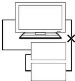
flowchart
graph TD
    A["Laptop"] --> B["Layer 1"]
    A --> C["Layer 2"]
    A --> D["Layer 3"]
    A --> E["X"]
    style A fill:#f9f,stroke:#333
    style B fill:#ccf,stroke:#333
    style C fill:#cfc,stroke:#333
    style D fill:#fcc,stroke:#333
    style E fill:#cff,stroke:#333
■When using i.LINK, do not turn off the power of or pull the cable from i.LINK devices, even if those i.LINK devices are not in use. This may affect the picture and the sound from an i.LINK device in use.
■If devices such as a DVD recorders, digital video cameras, PCs, and PC peripheral devices that are not compatible with this TV, are connected to the TV using i.LINK, other i.LINK connections may be disrupted.
■When device recognition, control, recording, or playback, on an i.LINK connected device does not function correctly, correct operation may be restored by disconnecting and reconnecting the i.LINK cable.
■When connecting multiple i.LINK devices, depending on the specifications and the interoperability of the connected devices, their operation may not be stable. In that case, disconnecting all devices not in use and changing the method of connection may result in stable operation.
To connect an i.LINK device, follow these steps:
1 Connect the i.LINK cable (B) to the 4-pin i.LINK terminal (A). The i.LINK connector must match your device cable type. (There are no separate audio inputs for i.LINK.)

■Make sure the shapes of the terminal and the plug match, and insert the plug into the terminal straight, not on an angle.
■Use either one of the terminals. These two terminals do not differ in quality or function.
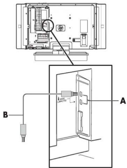
A: i.LINK connector on TV
B: i.LINK cable to i.LINK device
2 Connect the cable to the i.LINK device.
3 Turn on the device.
4 Connect power to the TV (see page 25).
5 Turn on the TV; see "Turning the TV On and Off (Standby)" on page 27.
6 Select the input source for the TV by pressing the Input button on the remote control or on the TV, or press i.Link on the remote control and select the source.
7 Define the i.LINK items in the Menu screen displays; refer to "Using the i.LINK Setup" on page 63.
For information on using and controlling an i.LINK device, refer to "Operating an i.LINK device" on page 37.
Connecting a component device
1 Connect the component cable (B) to the Component In (Y, Pb, Pr) connectors. There are two sets of component connectors you can use: Input 1 (A) or Input 2 (E). (Input 1 shown.)
A: Input 1, with component, composite video, and audio connectors
B: Component video cable
C: Audio cable
D: Component device output connectors
E: Input 2, with component, composite video, and audio connectors
2 Connect the component audio cable (C) to the L/R audio connectors in the terminals area.
3 Connect the cables to the device (D).
4 Turn on the device, and start play.
5 Connect power to the TV (see page 25).
6 Turn on the TV; see "Turning the TV On and Off (Standby)" on page 27.
7 Select the input source by pressing the Input button on the remote control or on the TV.
8 Define items in the Menu screen displays; refer to "Using the OSD Menus" on page 55.
Connecting an S-video or AV video device
A VCR, game console, camcorder, or some other audiovisual equipment can be connected using Input 3 terminals.
Input 3 has both S-video and AV video connectors, which share L/R audio connectors. Connect only one video input for Input 3.
1 Connect the video equipment to the INPUT 3 connectors:
■For a VCR, DVR, or other device that has an S-video connector, use an S-video cable (A) and the S-video connector.
Or
■For a VCR, DVR, or other device that has a composite connector, use a composite cable (B) and the Video connector.
22 HP Pavilion LCD HDTV User's Guide
A: S-video cable
B: Video cable composite connector
C: Video cable audio connectors
D: Composite video equipment output connectors
2 Connect the audio cable connectors (C) to the left and right audio connectors in Input 3 area.
3 Connect the cables to the device (D).
4 Turn on the device, and start play.
5 Connect power to the TV (see page 25).
6 Turn on the TV; see "Turning the TV On and Off (Standby)" on page 27.
7 Select the input source by pressing the Input button on the remote control or on the TV.
8 Define items in the Menu screen displays; refer to "Using the OSD Menus" on page 55.
Connecting a VCR for recording
1 Connect the VCR output (C) for playback using the Input 3 connectors, either S-video or AV video (composite); see the previous procedure, "Connecting an S-video or AV video device" on page 22.
2 Connect the VCR for recording by connecting the input to the VCR (E) to the Monitor Out/Rec Out terminals; use the S-video connector or the video connector. The two terminals share the audio connectors. The figure shows using the video connectors and an AV cable (D).

■The S-video terminal has priority over the video terminal.
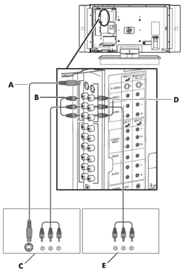
A: S-video cable to Input 3
B: Video cable to Input 3
C: VCR output connectors
D: Video cable from Monitor Out/Rec Out to VCR input
E: VCR input (composite video and audio) connectors
3 Define the screen size to record in the Menu screen display; see REC Picture Size under "Using the Video Setup" on page 62.
Connecting a PC
Use these instructions when connecting a PC or other source equipment to the TV Input 5 terminal to view the PC desktop as a selectable input source. You can use a DVI-I cable (sold separately) or RGB-to-DVI conversion cable (sold separately).

Refer to "PC Compatibility Chart" on page 77 for a list of PC signals compatible with the TV.

CAUTION: Unplug power for the TV and all connected components before connecting a PC. Ensure that the PC is powered off.
1 Connect the PC or source equipment video cable to the TV by using Input 5 (A).
■For a DVI-I connector on your PC, use a DVI-I cable (sold separately).
Or
■For a VGA connector on your PC, use a RGB-to-DVI conversion cable (sold separately).
A: Input 5, with DVI-I video, and audio (C) connectors
B: DVI-I video cable
C: Input 5 audio connector
D: Audio cable
E: PC DVI-I video and audio output connectors
24 HP Pavilion LCD HDTV User's Guide
A: Input 5, with DVI-I video, and audio (C) connectors
B: RGB-to-DVI video conversion cable
C: Input 5 audio connector
D: Audio cable
E: PC RGB video and audio output connectors
2 Connect the source audio cable to the Input 5 audio connector (C).
3 Connect power to the TV (see page 25).
4 Turn on the TV; see "Turning the TV On and Off (Standby)" on page 27.
5 Connect the power, and turn on the PC or source equipment.
6 Select the input source by pressing the Input button on the remote control or on the TV.
7 Define the type of device connected to Input 5 (DVI) by using Input Select under Options in the Menu screen displays; refer to "Using the Options Menu" on page 61.
Connecting an external sound system
Use the Digital Audio Output connector on the back of the TV to provide audio to an external sound system, such as a digital receiver or a surround sound system.

CAUTION: Unplug power for the TV and all connected components before connecting an external sound system. Ensure that the external sound system is powered off.
1 Connect the external sound system to the Digital Audio Output connector: Use the digital audio connector for an optical audio cable connection to a digital receiver or surround sound speaker system.
A
A: Digital Audio Output terminal
2 Connect power to the TV (see page 25).
3 Turn on the TV; see "Turning the TV On and Off (Standby)" on page 27.
4 Connect power and turn on the external sound system.
5 Define the digital audio format in the Menu screen display; refer to "Using Audio Setup" on page 63.
Connecting power to the TV
Use these steps to attach the cable clamp (select models only), connect the AC power cord, bundle cords with cable clamp and cable tie.
1 Connect the power cord to the TV (A) and secure it in the clamp (B).
2 Push the cable clamp (select models only) into the pedestal cover screw hole (C).
3 Bundle the cords with the cable clamp and the cable tie (D).
4 Connect the power cord to the AC power outlet.
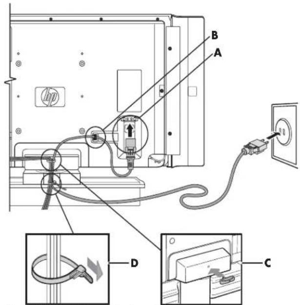
A: AC Input terminal with power cord
B: AC cord clamp
C: Cable clamp
D: Cable tie
Turning On the TV
Turning the TV On and Off (Standby)
The TV has an Power button (E) on the top of the display. You can also use the remote control buttons to turn on the TV.
Pressing the Power button either turns the TV on or places it into standby, which is a reduced power state.
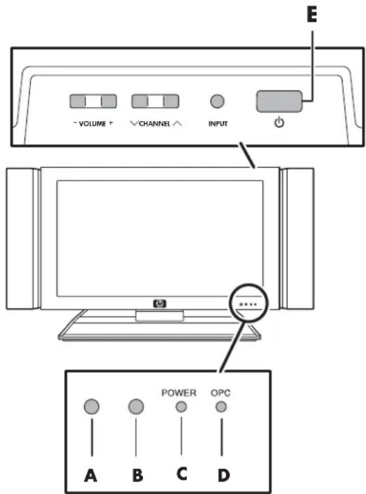
A: OPC sensor
B: Remote control sensor
C: Power indicator
D: OPC indicator
E: Power button
The Power indicator (C) on the front of the display shows the power status of the unit.
| Power Indicator Power Status | |
| Off Standby (Off) | |
| Lights blue Ready (On) | |
If the TV is not used for an extended period of time, press the Power button to place the TV into standby, and then unplug the power cord.

CAUTION: DO NOT remove the power cord while the CableCARD is inserted.
The Optical Picture Control (OPC) indicator (D) on the front of the display shows the TV status.
| OPCIndicator TV Status | |
| Off Off is selected in OPC setting. | |
| Lights green On or On:Display is selected in OPC setting. | |
| Lights red CableCARD is downloading data. |

CAUTION: Do not remove the cord when the OPC indicator is red.
Using the TV buttons
■ Press the Power button (E) on the top of the TV. The TV is on or in standby.
Using the remote control buttons
1 Press the TV button at the top of the remote control.
TV
2 Point the remote control at the display, and press the remote control Power button.

The TV is on or in standby.

The initial setup starts when the TV powers on for the first time. If the TV has been turned on before, the EZ setup will not be invoked. See "Starting EZ Setup" on page 59 to start the EZ setup from the Setup menu.
Using the First-Time Setup Wizard
Initial Setup
When turning on the TV for the first time, it automatically memorizes the broadcasting channels where you live. Perform the following steps before you press TV Power on the remote control unit.
1 Insert the batteries into the remote control unit.
2 Connect the antenna cable to the TV.
3 Plug in the AC cord to the AC outlet.
Language setting
1 Select from among three languages: English, French, and Spanish.
2 Press the up arrow and down arrow buttons on the remote control to select the desired language listed on the screen, and then press Select.
Standby mode setting
Select the standby mode setting.
■Mode 1: Starting TV is quick from standby.
■Mode 2: Power consumption is small when in standby.
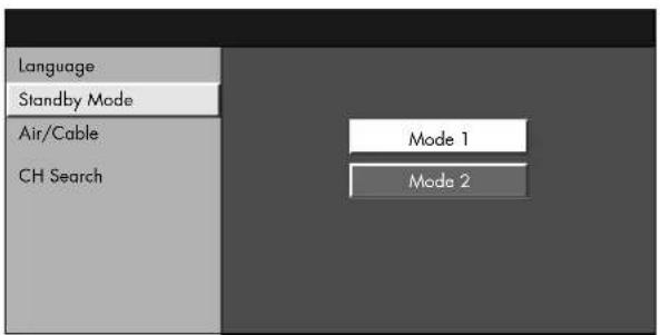

When the CableCARD is inserted, power consumption is higher.
Antenna setting
1 Press the left arrow and right arrow buttons on the remote control to select Air or Cable for analog. Then press the down arrow button to move down.
2 Press the left arrow and right arrow buttons to select Standard, HRC, or IRC for digital (cable).
3 Press Select to enter the setting.
■This operation makes the TV search for both analog and digital (cable).
■There are three types of CATV systems, including Standard, HRC, and IRC. Select the one that matches your TV.

Digital (cable) setting cannot be selected when a proper CableCARD is inserted.
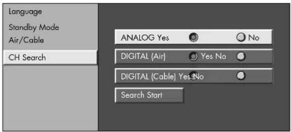
Channel search
Channel search automatically searches for a signal from all channels in the area.
1 Press the left arrow and right arrow buttons on the remote control to select Yes or No for Analog, and then press the down button to move down.
2 Press the left arrow and right arrow buttons on the remote control to select Yes or No for Digital (Air), and then press the down button to move down.
3 Press the left arrow and right arrow buttons on the remote control to select Yes or No for Digital (Cable), and then press the down button to move down.
4 Select Search Start, and then press Select.
Example
| MENU [Setup ... CH Setup ... CH Search] | |||
| ANALOG [ ]25 [ ]20 FoundAir |

| MENU [Setup ... CH Setup ... CH Search] | |||
| DIGITAL [ ]25 [ ]20 FoundAir |

| MENU | [Setup ... CH Setup ... CH Search] | ||
| DIGITAL [ ]25 [ ]25 FoundCable | |||


If no channel is found, check the input connection to your TV, and run the EZ setup again.
Using the Remote Control
Operating the TV or the Selected Device
The remote control operates the TV, your cable or satellite set-top box, your DVD/VCR, your audio receiver, and your HP Media Center PC.
To use the remote control:
1 Press the TV, DVD, STB, PVR, AUX, VCR, Audio, or HP button to select the home entertainment device (TV, DVD, set-top box, personal video recorder, auxiliary, VCR, audio receiver, HP MCPC, or HP DEC) to control.

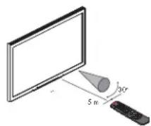
Use the remote control within a distance of 16.4 feet (5 meters) from the front of the TV remote control sensor window and at the maximum horizontal and vertical angles of 30 degrees.
2 For the TV, point the remote control at the remote control sensor on the display. For home entertainment devices, program the remote control, see "Programming the remote control for a home entertainment device" on page 44, and point the remote control at the home entertainment device's sensor.
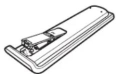
Installing or replacing remote control batteries
When the batteries are low, the selected Mode button (TV, DVD, STB, PVR, AUX, VCR, Audio, or HP) on the remote control blinks once every 5 seconds when a
button is pushed. Insert three AAA non-rechargeable batteries into the remote control ensuring that you place them with the proper polarity.
1 Press and open the cover on the back of the remote control.
2 Insert the batteries into the remote control, and make sure that you match polarities.
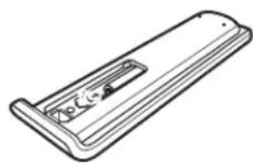
3 Close the cover.
Do not mix different types of batteries together (e.g., alkaline and carbon-zinc) or old batteries with fresh ones.
Be sure to follow the correct polarity when installing the batteries as indicated in the battery compartment. Reversed batteries may cause damage to the device.
When not using the remote for a long period of time, remove the batteries to prevent damage or injury from possible battery leakage.
Do not try to recharge batteries that are not intended to be recharged; they can overheat and rupture. Follow the battery manufacturer's directions for the batteries you are using.
Always remove batteries as soon as they become weak. Weak batteries can leak and severely damage the unit. The battery life depends on how much the remote control is used. Replace batteries when remote control operation becomes erratic.
Do not take apart the batteries, heat them, or throw them into a fire.
Identifying the remote control buttons
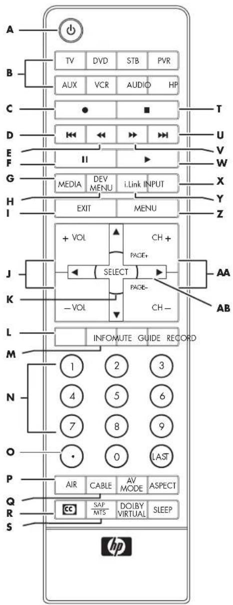
| Name Description Icon | ||
| A P o w | Press Power to turn on or off the TV or selected home entertainment device. | |
| B TV, DVD, STB, PVR, AUX, VCR, Audio, or HP | Press one of these buttons once to select a home entertainment device to control. To program the remote control to operate with a home entertainment device, see “Programming the remote control for a home entertainment device” on page 44. | TV |
| C Record | Press Record to start recording from the selected recordable home entertainment device (VCR, DVD recorder, i.LINK, HP MCPC, or HP DEC). | |
| D Skip backward | Press Skip backward to go back to the beginning of the current chapter (DVD). | |
| E Rewind | Press Rewind to rewind the selected home entertainment device (VCR, DVD, i.LINK, HP MCPC, or HP DEC). | |
| F Pause | Press Pause to pause the selected home entertainment device (VCR, DVD, i.LINK, HP MCPC, or HP DEC). | II |
| G Media | Function not available. | MEDIA |
| H Dev Menu | Function not available. | DEV MENU |
| I Exit | Press Exit to go back one submenu of the selected home entertainment device's menu or submenu. | EXIT |
| J Vol | Press + Vol (-Vol) to raise (or lower) the sound. |  |
| K S e l e | Press Select after entering a channel number.Press Select to choose the current menu option. |  |
| L M u t | Press Mute to turn sound off or on. |  |
| M I n f o | Press Info to view a channel banner containing information on your current program. | INFO |
| N K e y p | Press the keypad (0-9) to directly select channels. |  |
| O . ( P e | Press (period) to enter a period or dash for a subchannel number of a digital channel. For example, channel 123.1 or 4-1. |  |
| P Air | Press Air to view the signal connected to the Air input. | |
| Q C a b l | Press Cable to view the signal connected to the Cable input. | |
| R CC | Press CC to display closed caption content. | |
| S S A P | Press CAP/MTS to select an available secondary audio program. | |
| Name Description Icon | ||
| T S t o | Press Stop to stop the selected home entertainment device. |  |
| U S ki p forward | Press Skip forward to skip to the beginning of the next chapter (DVD). |  |
| V F a s Forward | Press Fast-Forward to fast-forward the selected home entertainment device (VCR, DVD, i.LINK, HP MCPC, or HP DEC). |  |
| W Play | Press Play to view the selected home entertainment device (VCR, DVD, i.LINK, HP MCPC, or HP DEC). |  |
| X In put | Press Input to view the Input Source menu. |  |
| Y i.LINK | Press i.LINK to display the i.LINK device menu. |  |
| Z Menu | Press Menu to open the onscreen display (OSD). Press Menu again to exit the menu or submenu and return to your TV display. |  |
| AA CH Page+/- | Press CH + (or CH -) to select the next higher (or lower) channel. Page function not available. |  |
| AB Up/ down/ left/right arrows | Press the arrow keys to move the cursor in the menu screens. |  |
Identifying the remote control buttons (cont.)
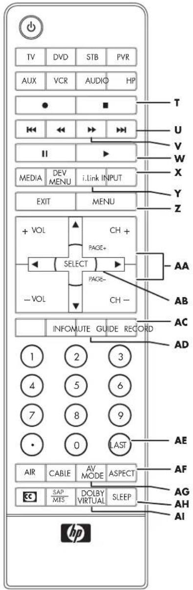
| Name Description Icon | ||
| AC Record | Function not available. | RECORD |
| AD Guide | Press Guide to display the guide of your selected home entertainment device. | GUIDE |
| AE Last | Press Last to recall the previous channel you were viewing, or the previous input mode. | LAST |
| AF Aspect | Press Aspect to change the dimensions of your display. The options depend on what is currently viewed. | ASPECT |
| AG AV Mode | Press AV Mode to select one of the AV or PC picture modes.■ AV modes: Standard, movie, game, user, dynamic, or dynamic (fixed).■ PC modes: Standard, user. | AV MODE |
| AH Sleep | Press Sleep to set the timer in this order: 30, 60, 90, or 120 minutes. | SLEEP |
| AI Dolby Virtual | Press Dolby Virtual to turn Virtual Dolby Surround on and off. | DOLBY VIRTUAL |
Adjusting the Volume
Press the (+) or (−) Vol buttons on the remote control to increase or decrease the sound. The indicator bar on the TV shows the increase or decrease.
Muting the sound
1 Press the Mute button to temporarily turn off the sound.
2 Press the Mute button again to restore the sound back to the previous level.
Changing Channels
Press the (+) or (−) CH buttons on the remote control to change the channel up or down. This TV allows you to select up to 125 channels (1 to 125). To select a channel, enter a one-digit, two-digit, or three-digit number, or use the channel up or down buttons.
To select a channel number (for example, channel 25):
Complete the following procedure within 4 seconds.
1 Press the 2 button on the remote control.
2 Press the 5 button.
3 Press Select.
To select a subchannel number (for example, 123.1):
Press 1, 2, 3, . (period), 1, and then Select on the remote control.
Selecting the last channel
Press the Last button on your remote control to view the previous channel you were viewing.
Operating a DVD or other device
After programming a home entertainment device into your remote control, press a device button on the top of your remote control. Use the Record, Stop, Rewind, Fast-Forward, Pause, and Play buttons to operate a DVD or other connected device. The Skip Forward and Skip Backward buttons work with DVD players.
For information on how to program a device into your remote control, see "Programming the remote control for a home entertainment device" on page 44.
Displaying program information
Pressing the Info button displays a banner with information about the current program you are viewing. Pressing it again, with the banner still displayed, gives you more detailed information when available.
If the program you are receiving is copy protected, an icon is displayed in the program information.
Recording digital programs with an i.LINK device, or recording digital audio with digital audio output terminals, is restricted.
| Icon Description | |
 | Digital copying prohibited |
 | One digital copy only |

Sometimes the name of the program is not broadcast. In that case, the program name is not displayed.
Selecting the Input Source
Pressing the Input button displays the Input Source menu. Use the up arrow and down arrow to highlight an input source and press Select.
Changing the View with the Aspect Button
Pressing the Aspect button scrolls through the Aspect modes. Your options depend on what is currently viewed.
■Side Bar: Shows the standard 4:3 ratio picture image in the center of the TV with dark bars on the left and right.
■Smart Stretch (S.Stretch): Horizontally stretches the TV picture to fill the screen. Suitable for stretching normal 4:3 programs to fill the screen.
■Zoom: Proportionally stretches the TV picture, but clips the top and bottom of the image to fit the screen. Eliminates black bars.
■Stretch: Shows high-definition TV in its normal format.
■Dot by Dot: Detects the resolution of the signal and displays an image with the same number of pixels on the screen.
For more information, see "Selecting the view aspect" on page 63.
Turning On Captions
Pressing the CC button displays captions. To assign your preferences for captions, see "Using Closed Caption" on page 64.
Setting SAP/MTS stereo mode
Pressing the SAP/MTS button scrolls through the available Secondary Audio Programs (SAP)/Multi-channel Television Sound (MTS) features.
MTS receives mono sound, stereo sound, and Secondary Audio Programs. The SAP feature allows a TV station to broadcast other information, such as another language or weather information.
You can enjoy hi-fi stereo sound or SAP broadcasts where available.
■Stereo broadcasts
■View programs such as live sporting events, shows, and concerts in dynamic stereo sound.
■SAP broadcasts
■Receive TV broadcasts in either Main or SAP sound.
■Main sound: The normal program soundtrack (either in mono or stereo).
■SAP sound: Listen to second language, supplementary commentary and other information (SAP is mono sound).
If stereo sound is difficult to hear:
■Obtain a clearer sound by manually switching to fixed mono-sound mode.

MTS only operates while in TV mode.
Turning On Dolby Virtual
Pressing the Dolby Virtual button delivers a Dolby Virtual effect through the speakers. Dolby Virtual produces a natural and realistic surround sound. Pressing the Dolby Virtual button again returns the sound to normal.
Setting the Sleep Timer
Pressing the Sleep button starts a timer for the TV to automatically turn off. Setting the Sleep Timer to 30 means your TV automatically turns off in 30 minutes.
| Minutes Description | |
| 30 | Sets the timer to 30 minutes. |
| 60 | Sets the timer to 1 hour. |
| 90 | Sets the timer to 90 minutes. |
| 120 | Sets the timer to 2 hours. |
Adjusting TV Settings
Use the onscreen display to adjust your picture, audio, and other settings. For more information, see "Changing the TV Settings" on page 55.
Opening and exiting the OSD
Pressing Menu displays the OSD menu. Pressing the Menu button again, leaves the current menu and returns you to the TV display. Pressing Exit with a submenu displayed takes you back one menu.
Operating an i.LINK device
1 Connect an i.LINK device to the TV. For information on connecting an i.LINK device, see "Connecting an i.LINK device" on page 19.
2 Press the i.LINK button on the remote control to open the i.LINK control panel.
3 Use the arrow buttons on the remote control to highlight a function and press Select.
Or
Use the Record, Stop, Rewind, Fast-Forward, Pause, and Play buttons to operate the i.LINK device.
4 Press the i.LINK button to hide the i.LINK control panel.
About i.LINK
i. LINK is an interface connection using a serial transfer system that transfers multimedia data, such as digital images and digital sound, between devices that have i. LINK terminals.
i. LINK is a term defined in the IEEE 1394 (Institute of Electrical and Electronics Engineer) standard. Currently, the transfer speeds are at 100 Mbps, 200 Mbps, and 400 Mbps, each of them expressed as S100, S200, and S400 respectively. The maximum speed for this TV is 400 Mbps.
i.LINK devices that can be connected
Only D-VHS decks, AV HDD recorders, and Blu-ray Disc recorders can be connected to this TV with i.LINK. Device recognition, control, recording, and playback operations may not be possible on some devices. Other devices such as DVD recorders, digital video cameras, PCs, or PC peripheral devices do not meet the specifications for this TV and cannot be connected with i.LINK.
Materials that can be recorded with i.LINK
Only digital programs can be recorded by i.LINK devices connected to this TV using i.LINK. i.LINK recording is not compatible with analog broadcasts or external input signals (Inputs 1 through 5).
Setting the recording mode (i.LINK)
The function for automatically adjusting the recording mode of connected i.LINK devices can be turned on or off. Most of the currently available i.LINK devices automatically recognize the transfer rates of the pictures and sound being recorded. These devices control the recording mode accordingly. Set this Mode to Pass through in normal circumstances.
Depending on the i.LINK devices used and the type of broadcast being recorded, this TV may not adjust the recording mode properly. In this case, set the recording mode to Pass through.
1 Press the Menu button on the remote and the menu screen displays.
2 Press the up arrow and down arrow buttons on the remote control to highlight Digital Setup, and press Select.
3 Press the up arrow and down arrow buttons on the remote control to highlight i.LINK Setup, and then press Select.
4 Press the up arrow and down arrow buttons on the remote control to highlight Recording Mode, and then press Select.
5 Press the left arrow and right arrow buttons on the remote control to select Auto or Pass through, and then press Select.
Normally, this should be set to Pass through.
6 Press the Menu button to view the display.
Setting the standby mode (i.LINK)
Power consumption during standby mode can be minimized by changing the setting of the Standby Mode in i.LINK Setup. When i.LINK is not in use, select Inactive in Standby Mode.
1 Press the Menu button on the remote control, and the menu screen displays.
2 Press the up arrow and down arrow buttons on the remote control to highlight Digital Setup, and press Select.
3 Press the up arrow and down arrow buttons on the remote control to highlight i.LINK Setup, and then press Select.
4 Press the up arrow and down arrow buttons on the remote control to highlight Standby Mode, and then press Select.
5 Press the left arrow and right arrow buttons on the remote control to select Active or Inactive, and then press Select.
Active: Power continues to pass through the i.LINK circuit so data can be relayed.
Inactive: Power consumption is minimized during standby mode. Data cannot be relayed at this setting.
6 Press the Menu button to view the display.
■When the main power of the TV is in standby mode (Power indicator lights off), i.LINK control commands cannot be received from an i.LINK device. This does not change if the Standby Mode is set to Active. To control the TV from an i.LINK device, turn the TV power on (Power indicator lights up in blue).
■Data cannot be relayed between i.LINK devices when all of the following conditions are met: 1) More than one i.LINK device is connected to the TV with i.LINK cables, 2) Standby Mode is set to Inactive, and 3) The power of the TV is in standby mode (Power indicator lights off). When the TV is connected between two i.LINK devices in series, select Active in Standby Mode or connect the TV at an end of the series as shown in the diagram.
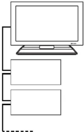
flowchart
graph TD
    A["Computer monitor"] --> B["Box 1"]
    A --> C["Box 2"]
    A --> D["Box 3"]
    A -.-> E["Line"]
    style A fill:#f9f,stroke:#333
    style B fill:#ccf,stroke:#333
    style C fill:#ccf,stroke:#333
    style D fill:#ccf,stroke:#333
Selecting an i.LINK device
To control an i.LINK device from the TV, you must first choose the i.LINK device to be controlled. One i.LINK device can be chosen from up to 16 i.LINK connected decks. All i.LINK devices connected with i.LINK cables should automatically appear in the selection screen.
1 Press the i.LINK button on the remote control to display the i.LINK control panel.
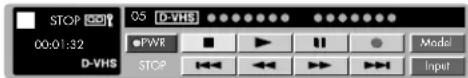
■If no i.LINK device is detected, the message No i.LINK model is available appears.
■If no i.LINK device is selected, the selection screen appears. Go to step 3.
2 Press the arrow buttons on the remote control to highlight Model, and press Select to view the Selection screen.
![i.UNK 1/1 [Thu] 1:33AM Type Which model do you use? Manufacturer Model Cancel Connection](/content/2026/04/693369/images/d2bd8b1b56d2a8d4627868c94803a134f5585a6469bda4d1a3ea9124084237bc.jpg)
3 Press the up and down arrow buttons on the remote control to select a device, and then press Select. The control panel for the i.LINK device appears.
■Incompatible devices with this TV do not appear in the selection screen.
■The manufacturer's name and model name of some devices may not display correctly. Follow the steps in "Deleting registered i.LINK devices" on page 39, and cancel all i.LINK devices you have registered before reconnecting the i.LINK cable.
■Grayed-out devices are not recognized by the TV and cannot be selected. The device may not be connected properly.
Disabling the TV's operation of an i.LINK device
By disabling the TV's operation of an i.LINK device, the device can be operated from another i.LINK device.
1 Press the i.LINK button on the remote control to display the i.LINK control panel.
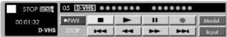
■If no i.LINK device is detected, the message No i.LINK model is available appears.
■If no i.LINK device is selected, the selection screen appears. Go to step 3.
2 Press the arrow buttons on the remote control to highlight Model, and press Select to view the Selection screen.
3 Press the down arrow button to highlight Cancel Connection, and then press Select.
Operation of the i.LINK device from the TV is disabled.
![iLINK 1/1 [Thu] 1:33AM Which model do you use? Type Manufacturer Model Cancel Connection](/content/2026/04/693369/images/2ff7e0b55eb9a1da14df64a9e0ec0b76a48d2439e4c8f0f897e09b85c9777c67.jpg)
Deleting registered i.LINK devices
Registered i.LINK devices can be deleted from a list. If an i.LINK device is connected, it cannot be deleted from the list.
1 Disconnect the i.LINK device.
2 Press the i.LINK button on the remote control to display the i.LINK control panel.
3 Press the arrow buttons on the remote control to select Model, and press Select to view the Selection screen.
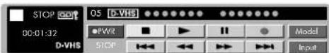
4 Press the up and down arrow buttons on the remote control to select a device to be deleted, and then press Select.
![iLINK 1/1 [Thu] 1:33AM Type Which model do you use? Manufacturer Model Cancel Connection](/content/2026/04/693369/images/6441df93cdc5a0289ccc8341a652e51d2cd87faea40910b93b91d5d086620c21.jpg)
5 Press the Select button on the remote control, highlight Delete, and then press Select.
■The selected i.LINK device is deleted from the list.
■ Select Cancel if you do not want to delete any device.
Controlling an i.LINK device
An i.LINK compatible device can be controlled from the TV using the i.LINK control panel. Also refer to the user guide of the i.LINK device to be used with this TV.
Basic operation
1 Press the i.LINK button on the remote control to display the i.LINK control panel.
2 Press the arrow buttons on the remote control to highlight a function, and then press Select.
i.LINK control panel (D-VHS decks)
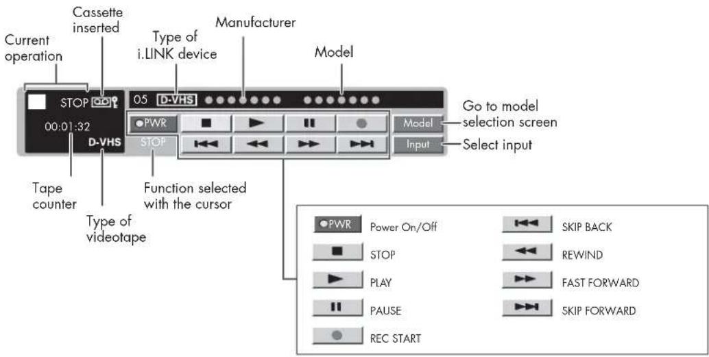
i.LINK control panel (AV HDD recorder or Blu-ray Disc recorder)
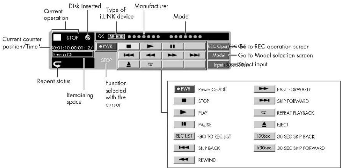
*If you start playback before time is displayed, time will not be displayed during the playback.
■ The input selection button is used to select either i.LINK input or others.
■The Eject button is displayed for Blu-ray Disc recorders only.
■If you begin playback before time is displayed, time won't be displayed during playback.
■IEEE1394 is the IEEE's international standard.
■A copy protection technology is used on i.LINK devices that incorporate copyright protection. This technology has received the approval of the Digital Transmission Licensing Administrator (DTLA), an organization that administers copyright protection technologies. Some picture and sound data have restrictions on duplication. Such data cannot be digitally copied using the i.LINK. Some picture and sound data may not be able to be sent back and forth between an i.LINK device that has DTLA copyright protection technology and one that does not.
Notes on i.LINK connection of D-VHS deck, AV-HDD recorder, or Blu-ray Disc recorder
■Even when a connected i.LINK device is playing, input signal can be switched to input mode other than i.LINK by shifting the cursor to the input selection button and pressing Select.
■This TV may not be able to operate some i.LINK devices using the control panel, or to display picture and/or sound input from some i.LINK devices.
■When the TV's control panel is used to record a program, what is recorded with the i.LINK device are the pictures and sound of the digital program that the TV is receiving.
■The i.LINK control panel cannot be used during timer recording.
■There may be some programs which i.LINK devices cannot record.
■With some i.LINK devices, the quality of the picture may be distorted during fast-forwarding or rewinding.
Notes on i.LINK connection of D-VHS deck
■Depending on the D-VHS deck, this TV's i.LINK may not allow viewing of VHS and S-VHS tape or analog recorded D-VHS tape. In this case, connect the D-VHS deck's analog output with the TV's analog input, and switch the TV's input mode to external input.
If a D-VHS deck is operated with the TV's control panel during timer recording, the recording may fail. Do not use the TV's control panel to operate the D-VHS deck during timer recording.
■To record the picture and sound of a digital program which the TV is receiving, use D-VHS tape. VHS or S-VHS tape will not record.
Notes on i.LINK connection of AV-HDD recorder or Blu-ray Disc recorder
■Depending on the AV-HDD recorder or Blu-ray Disc recorder, some functions, such as playback during recording, display of the recording list screen during recording, and so on, may not be able to be operated.
■Depending on the AV-HDD recorder or Blu-ray Disc recorder, playback may stop automatically when switching to another i.LINK device.
If an AV-HDD recorder or Blu-ray Disc recorder is operated with the TV's control panel during timer recording, the recording may fail. Do not use the TV's control panel to operate the AV-HDD recorder or Blu-ray Disc recorder during timer recording.
Notes on i.LINK connection of AV-HDD recorder
■Depending on the AV-HDD recorder, it may be possible to change the recorder's operations mode (D-VHS mode, HDD recorder mode). When the operations mode is D-VHS mode, the HDD recorder is recognized as a D-VHS deck.
Automatic input switching to i.LINK
Input mode can be set to automatically switch to i.LINK when an i.LINK device connected to the TV is played.
1 Press the Menu button on the remote control to display the menu screen.
2 Press the up arrow and down arrow buttons to highlight Digital Setup, and then press Select.
3 Press the up arrow and down arrow buttons to highlight i.LINK Setup, and then press Select.
4 Press the up arrow and down arrow buttons to highlight i.LINK Autoswitch, and then press Select.
5 Press the left arrow and right arrow buttons to select Yes, and then press Select.
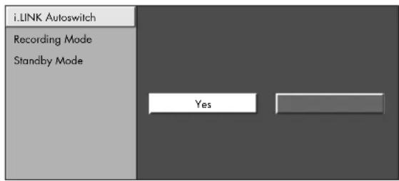
6 Press the Menu button to view the display.
Recording digital programs with a D-VHS deck (i.LINK)
Refer to the user guide of the D-VHS deck to be used with this TV.
1 Connect an i.LINK device.
2 Select a digital program to be recorded.
3 Press the i.LINK button on the remote control to display the i.LINK control panel.
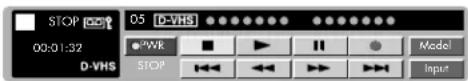
4 Press the arrow buttons on the remote control to highlight the record button on the control panel, and then press Select on the remote control.
5 Press the arrow buttons on the remote control to highlight the Stop button on the control panel, and then press Select on the remote control.

■Input mode cannot be switched to i.LINK during recording.
■When a D-VHS deck connected to the TV is under timer recording, the deck cannot be operated using the TV's control panel.
Recording digital programs with an AV-HDD recorder or Blu-ray Disc recorder
Refer to the user guide of the AV-HDD recorder or Blu-ray Disc recorder to be used with this TV.
1 Connect an i.LINK device.
2 Select a digital program to be recorded.
3 Press the i.LINK button on the remote control to display the i.LINK control panel.
4 Press arrow buttons on the remote control to highlight Rec Oper., and then press Select.
5 Press the arrow buttons on the remote control to highlight the Record button on the control panel, and then press Select on the remote control.
6 Press the arrow buttons on the remote control to highlight the Stop button on the control panel, and then press Select on the remote control.
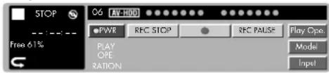

■Input mode cannot be switched to i.LINK during recording.
■When the input mode is i.LINK, you cannot operate recording.
■When an AV-HDD recorder or Blu-ray Disc recorder connected to the TV is under timer recording, the recorder cannot be operated using the TV's control panel.
Playing back using Rec List (i.LINK)
1 Press the i.LINK button on the remote control to display the i.LINK control panel.
2 Press the arrow buttons on the remote control to select Rec List, and then press Select to display the Rec List.
3 Press the up arrow and down arrow buttons to select the desired program, and then press Select.
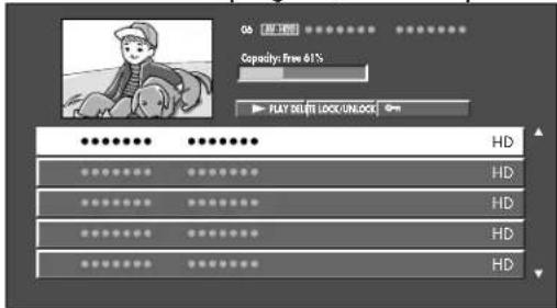
4 Press the left arrow and right arrow buttons to highlight Play, and then press Select.
5 Press the left and right arrow buttons to highlight From Top or From current position, and then press Select.
| Selected item Description | |
| From top Playback | starts from the beginning of the selected program. |
| From current position | Playback starts from the point playback stopped last time. |
Deleting a program from the Rec List
1 Highlight the program you want to delete, and press Select.
2 Highlight Delete and press Select.
3 Highlight Delete again, and press Select.
Locking a program on the Rec List
1 Highlight the program you want to lock, and press Select.
2 Highlight Lock/unlock, and press Select.
■Depending on the device connected, the audio and images of the program selected may not be displayed in the small play screen.
■Depending on the device connected, when the recording list is displayed during recording, the recording may stop.
■The program information displayed in the title (program name, date and time, and so on) is taken from the program information for the program broadcast at the time recording started.
■When recording several programs in succession, the program information displayed is that of the first program recorded at the time recording originally started.
■When playing back content recorded on other devices, the program information in the title may not be displayed correctly.
Selecting a Device to Control
After you program the device buttons on the top of the remote control, use the buttons to select the device you want to control.
| Button Description | |
| TV Controls your TV (already programmed). | |
| DVD Controls your DVD. | |
| STB Controls your set-top box. | |
| PVR Controls your personal video recorder. | |
| Aux Controls your auxiliary device. | |
| VCR Controls your VCR. | |
| Audio | Controls your audio receiver. |
| HP | Controls your HP Media Center PC or HP Digital Entertainment Center (already programmed). |
Programming the remote control for a home entertainment device
Your HP remote control is programmable. Program the remote control to operate other home entertainment devices such as your VCR, DVD player, audio receiver, or set-top box. Manufacturer codes for compatible brands are listed at the end of this chapter. If the brand of your device is not listed, see "Searching for the device code" on page 44.
Programming the device code
The following steps describe how to program a device button if your brand is listed.
1 Turn on the TV. Turn on the device you would like to program.

Read steps 2 through 4 completely before proceeding. Highlight or write down the codes and device you wish to program before performing step 2.
2 Hold down a device button on the remote control for 5 seconds until the device button blinks, and then release the device button. The device button blinks one more time and then remains lit.
3 Locate the brand of your device and manufacturer's codes (see listing that follows).
4 Enter the first four-digit code. If the code is accepted, the device button flashes twice. If the code is not accepted, the device button flashes three times.

If the device button did not blink twice, then repeat steps 2 through 4, entering either the same code or the next code if provided.
5 Aim the remote control at the device, and press the Power button once. The device should turn off. If it does not respond, repeat steps 2 through 4, trying each code for your brand until you find one that works. If it still does not work, try searching for the code; see "Searching for the device code" on page 44.

If the device does not have a power button, press Play.
6 Repeat steps 1 through 5 for each device you want to control with the remote control.
Searching for the device code
If your device does not respond to the remote control after trying all codes listed for your brand, or if your brand is not listed at all, try searching for your code.
1 Turn on your home entertainment device.
2 Hold down a device button on the remote control for 5 seconds until the device button blinks, and then release the device button. The device button blinks one more time and then remains lit.
3 Enter 1, 1, 1, 1, and the device button blinks once and then remains lit.
4 Press and release the Power button once on the remote control. Wait until the device button stops blinking. Continue to press and release the Power button, waiting each time for the device button to stop blinking, until the home entertainment device turns off.

Each time you press the Power button, it is trying a different code. Be sure to wait until the device button stops blinking before pressing the Power button again. You may need to press the Power button several times before the correct code is found.
5 Once the home entertainment device turns off, press the Select button on the remote control to save the code.
Manufacturer's codes
The following charts include manufacturer codes for these home entertainment devices:
■DVD
■VCR
■DVD/VCR combo
■Home Theater in a Box
■Satellite box
■Cable box
■Satellite receiver/recorder
■Amplifier
■Miscellaneous audio manufacturer codes
■Audio cassette
■Audio system
■Phono
■PVR
■Receiver/tuner
DVD manufacturer codes
| Brand Code | Brand Code | Brand Code | |||
| Aiwa 0073 H | Hitachi 0065, 0067 P | Poneer 0027, 0032 | |||
| Apex 0000, 0001, 0003, 0004, 0016, 0028, 0029, 0030 | Irradio 0092 Proscan 0005, 0099 | ||||
| Audiovox 007 | 4 JVC 0007, 0010, | 0011, 0012, 0013 | Qwestar | 0057 | |
| Blaupunkt | 0078 | Kenwood | 0097, 0100 | RCA | 0005, 0024, 0038 |
| Bose | 0062, 0071 Koss | 0093 | Sampo 0058 | ||
| Broksonic | 0045 | Magnavox | 0020, 0035 | Samsung | 0006, 0017, 0033, 0041 |
| Clarion | 0046 Marantz | 0085 Sansui | 0060 | ||
| Classic | 0047 | Memorex | 0087 | Sanyo | 0059, 0063 |
| Daewoo | 0079, 0080 | Mintek | 0053 | Sharp | 0014, 0031 |
| Denon 0075, | 0095, 0096 | Mitsubishi | 0088, 0089, 0090, 0091 | Sherwood | 0061 |
| Emerson | 0048, 0049 | NAD | 0048, 0081 | Sony | 0015, 0018, 0034, 0039 |
| Fisher | 0050, 0076 | Nakamichi | 0054 | Sylvania | 0049, 0072, 0077 |
| Funai | 0049, 0064 | Norcent | 0055, 0056 | Techwood | 0083 |
| GE | 0005, 0051, 0102 | Onkyo | 0082, 0086 Toshiba | 0019, 0026, 0040, 0042 | |
| GoVideo | 0068, 0070 | Oritron | 0057 | Yamaha | 0084, 0098 |
| GPX | 0052 Panasonic | 0008, 0036, 0037 | Zenith | 0069, 0094 | |
| Harman Kardon | 0066 Philips | 0002, 0009, | 0021, 0022, 0023, 0043 | ||
VCR manufacturer codes
| Brand Code | Brand Code | Brand Code | |||
| Admiral 0073 | 0074,0101 | Daytron 0067 | 0083, 0102 JC Penney | 0046, 0047, 0048,0049, 0050, 0051,0053, 0054, 0057,0058, 0059, 0060,0065, 0079, 0085,0088, 0090 | |
| Aiko 0056 | Denon 0088 Jensen | 0057, 0058, 0068 | |||
| Aiwa 0055 | Dimensia 0043, 01 | 2 JVC | 0000, 0019, 0046,0047, 0048, 0068,0071, 0087, 0088 | ||
| Akai 0044, 0 | 0045,0068, 0069,0080, 0093 | Electrohome | 0051, 0090 Kenwood | 0046, 0047, 0048,0068, 0071, 0077 | |
| Audiovox | 0051 Emerson | 0044, 0049 | 0051, 0052,0053, 0055, 0061, 0069,0087, 0090, 0106 | KLH | 0059 |
| Bell &Howell | 0048 Fisher | 0048, 0089 | 0105 Kodak | 0051, 0053 | |
| Broksonic | 0023, 0049 Fuji | 0045, 0053 LG | 0051 | ||
| Calix 0051 | Funai 0055, | 0095 Lloyds | 0077, 0095, 0105 | ||
| Canon | 0053, 0054 Garrard | 0055 Logik | 0059, 0085 | ||
| Capehart | 0067, 0083 GE | 0040, 0043, 0050, 0053,0054, 0070, 0079, 0112 | LXI | 0051 | |
| Carver | 0060, 0110 | GoVideo | 0021, 0024, 0026, 0028,0034, 0079, 0081, 0085,0086 | Magnasonic | 0085, 0090, 0102 |
| CCE 0056, 0 | 0059 Goldstar | 0046, 0051, | 0079, 0090,0092 | Magnavox | 0008, 0053, 0054,0060, 0064, 0085,0110 |
| Citizen 0050 | 0051,0052, 0056,0095 | Gradiente | 0055, 0090 Marantz | 0046, 0047, 0048,0053, 0060, 0077,0092, 0110 | |
| Colortyme | 0046, 0096 HarmanKardon | Harwood | 0046, 0110 Matsushita | 0053 | |
| Craig | 0050, 0051,0059, 0085,0090, 0105 | Harwood | 0059 Memorex | 0033, 0048, 0050,0051, 0053, 0055,0064, 0073, 0074,0088, 0090, 0091,0097, 0105 | |
| CurtisMathes | 0043, 0046,0050, 0053,0054, 0077,0079, 0112 | Hitachi | 0025, 0036, 0037, 0057,0058, 0065, 0068, 0070,0088 | MGA | 0061, 0069 |
| Daewoo 0052 | 2, 0055,0056, 0067,0083, 0102 | JBL | 0098 MGN | 0079 | |
| Brand | Code | Brand | Code | Brand | Code |
| Minolta 0057 | 0058,0065,0088 | Pioneer 0047 | 0057,0071,0075,0078,0104 | Sharp | 0014,0015,0062,0073,0074,0091,0094,0101 |
| Mitsubishi 00 | 03,0005,0006,0057,0058,0061,0069,0071,0090 | Portland 0067 | 0083 Shintom | 0045,0058,0059,0085 | |
| Montgomery Ward | 0073,0074 Proscan 0043,01 | 12 Signature | 0073,0074 | ||
| Motorola 005 | 3,0073,0074 | Proton 0085 | Signature | 2000 | 0097,0101 |
| MTC 0050,0085 Quasar 0053 | 0054 Singer | 0053,0059,0072,0076,0085 | |||
| Multitech 005 | 0,0055,0059 | Radio Shack | 0051,0062,0074,0090 | Sony | 0007,0045,0063,0080,0082,0084,0098,0099 |
| NEC 0046,0047,0048,0068,0071,0077,0092 | Radio Shack/Realistic | 0048,0050,0051,0053,0054,0055,0062,0073 | STS | 0053,0065 | |
| Nikko 0051 | Radix | 0051 Sylvania | 0030,0032,0053,0054,0055,0060,0061,0110 | ||
| Noblex | 0050 | RCA | 0012,0016,0043,0044,0050,0053,0057,0058,0065,0070,0078,0079,0088,0107,0108,0112 | Symphonic | 0055,0077,0095,0105 |
| Olympus | 0053 | Realistic | 0048,0050,0051,0052,0053,0054,0055,0062,0073,0074,0079,0090,0094,0097,0105 | Tandy | 0048 |
| Optimus | 0051,0073,0074,0090,0094 | Ricoh 0072, | 0076 Tashiko | 0051 | |
| Optonica | 0062 | Runco | 0064 | Tatung | 0068 |
| Orion | 0087,0090,0106 | Samsung | 0029,0031,0035,0039,050,052,079,095 | Teac | 0055,0068,0107 |
| Panasonic | 002,004,009,020,053,054,066,085,105 | Sansui | 0047,0068,0071,0085 | Technics | 0053,0066 |
| Pentax | 0057,0058,0065,0070,0077,0088 | Sanyo 0022 | 0048,0050,0089,0097,0105 | Teknika | 0051,0053,0055,0090 |
| Philco | 0053,0054,0060,0088,0106 | Scott | 0049,0052,0061,0090 | Toshiba | 0010,0011,0052,0057,0061,0069,0100,0102,0105,0109 |
| Philips | 0017,0018,0053,0060,0062,0110 | Sears 0048 | 0051,0053,0057,0058,0065,0077,0088,0089,0090,0097,0105 | Totevision | 0050,0051,0090 |
| Brand Code | Brand | Code | Brand Code | ||
| Unitec 0095 | Video | Concepts | 0046, 0047, 0052, 0069, 0077 | XR-1000 0053 | , 0055, 0059 |
| Unitech 0050 | Wards 0050, 005 | 1, 0052, 0053, 0055, 0057, 0058, 0059, 0062, 0065, 0073, 0074, 0079, 0090, 0091, 0094, 0105, 0108, 0110 | Yamaha 0046 | , 0047, 0048, 0068, 0077 | |
| Vector Research | 0046, 0047, 0052, 0077 | WhiteWesting-house | 0095 Zenith 0027, 0038, 0045, | 0064, 0072, 0076, 0093 |
DVD/VCR combo manufacturer codes
| Brand | Code | Brand | Code | Brand | Code |
| GoVideo | 0026, 0028, 0068, 0070 | JVC | 0000, 0010 | Sanyo | 0022, 0063 |
| Hitachi | 0025, 0067 | Samsung | 0031, 0017 | Zenith | 0027, 0069 |
Home Theater in a Box manufacturer codes
| Brand | Code | Brand | Code |
| Bose | 0010, 0071 | Philips | 0022 |
| Onkyo | 0086 | Toshiba | 0025 |
Miscellaneous video manufacturer codes
| Type | Brand | Code | Type | Brand | Code |
| DVR | Philips | 0042 | PVR | TiVo | 0111 |
| Digital network recorder | Sony | 0041 |
Satellite box manufacturer codes
| Brand | Code | Brand | Code | Brand | Code |
| Alphastar | 0073 | Hughes | 0068 | Samsung | 0051, 0073 |
| Chaparral | 0069 | Janeil | 0067 | Sony | 0052, 0079 |
| DirecTV | 0046 | JVC | 0060 | Star Choice | 0076 |
| Drake | 0072 | Mitsubishi | 0047 | Star Trak | 0066 |
| Echostar | 0071 | Panasonic | 0050, 0056 | STS | 0065 |
| Express Vu | 0075 | Philips | 0045 | Toshiba | 0053, 0074 |
| Fujitsu | 0067 | Proscan | 0077, 0078 | Uniden | 0061, 0062 |
| GE | 0049, 0077, 0078 | Radio Shack 0063, | 0064 Zenith | 0054, | 0067 |
| General Instruments | 0063, 0064 RCA | 0077, 0078 | |||
| Hitachi | 0068 | Realistic | 0059 | ||
Cable box manufacturer codes
| Brand Code | Brand Code Brand Code | ||||
| ABC 0000, 0001,0002, 0030 | Motorola 0031 Scientific | Atlanta | 0002, 0023,0024, 0025 | ||
| Archer 0006, 0007 | Movie Time 0039 Signature 0000 | ||||
| Cableview 0003 | NEC | 0033 Sprucer | 0029 | ||
| Contec | 0034 NSC | 0039 Standard | Component | 0042, 0043 | |
| Eastern 0035 | Oak | 0034, 0041 | Starcom 0012, 0030 | ||
| GE | 0000 | Panasonic | 0027, 0029 | Stargate | 0012 |
| Gemini 0012, 0013 | Philips | 0008, 0009, | 0010,0011, 0013, 0017,0018, 0019, 0020 | Tocom | 0001, 0015 |
| General Instruments | 0000, 0032 | Pioneer | 0021, 0022 | United Cable | 0030 |
| Hamlin | 0036, 0037,0038, 0040,0044 | Proscan | 0000 Universal | 0004, 0006, | 0007 |
| Hitachi | 0000 | RCA | 0003, 0029, 0032 | Viewstar | 0017, 0034,0039 |
| Jerrold 0000, 0012,0015, 0016,0026, 0030,0032 | Realistic | 0006 Zenith | 0028 | ||
| Magnavox | 0017 Samsung | 0022 | |||
Satellite receiver/recorder codes
| Brand | Code | Brand | Code |
| Philips | 0057 | Sony | 0080 |
| RCA | 0055 | Zenith | 0058 |
Amplifier manufacturer codes
| Brand | Code | Brand | Code |
| Kenwood | 0048 | Pioneer | 0041 |
| Yamaha | 0001, 0053 | RCA | 0069 |
Miscellaneous audio manufacturer codes
| Type | Brand | Code | Type | Brand | Code |
| Digital audio tape | Sony | 0043 | Receiver/amplifier | Yamaha | 0001 |
| Tuner | Philips | 0022 | TV/VCR/tuner combo | Panasonic | 0012 |
Audio cassette manufacturer codes
| Brand Code | Brand Code | Brand | Code | |||
| Aiwa 0039 Onkyo | 0055 RCA 0070 | |||||
| Curtis Mathes 0041 | Optimus 0041, 0047 | Sansui 0057 | ||||
| Denon 0052 Panasonic | 0015, 0050 | Sanyo 0044 | ||||
| Fisher 0042, 0049 | Philips 0013 Sherwood | 0047 | ||||
| GE | 0070 Pioneer | 0018, 0041, 0045 | Sony | 0043 | ||
| Kenwood | 0048, 0056 | Proscan | 0070 | Technics | 0050 | |
| NAD | 0040 | Quasar | 0050 | Yamaha | 0053 | |
| Nakamichi | 0054 Radio Shack | 0047 |
Audio system manufacturer codes
| Brand | Code | Brand | Code | Brand | Code |
| Aiwa | 0039 | Nakamichi | 0054 | Scientific Atlanta | 0067 |
| Carver | 0051 | Panasonic | 0015, 0016 | Sony | 0043 |
| Curtis Mathes | 0041 | Philips | 0013, 0014 | Starcom | 0066 |
| Denon | 0052 | Pioneer | 0018, 0041 | Technics | 0050 |
| Harman Kardon | 0046 | RCA & Dimensia | 0031, 0032, 0033, 0034, 0035 | Yamaha | 0053 |
| Jerrold | 0066, 0068 | Sansui | 0057 | ||
| Kenwood 0048, 0056 Sanyo | 0044 | ||||
Phono manufacturer codes
| Brand | Code | Brand | Code |
| Kenwood | 0048 | Sony | 0043 |
| Pioneer | 0041 | Yamaha | 0053 |
PVR manufacturer codes
| Brand | Code | Brand | Code |
| Philips | 0001, 0004 | TiVO | 0002 |
| Sony | 0000, 0005 | Zenith | 0003 |
Receiver/tuner manufacturer codes
| Brand Code | Brand Code | Brand Code | |||
| Aiwa 0017, 0036, 0039 | Luxman 0064 Radio Shack 0047 | ||||
| BOSE 0010 Marantz 0019 RCA 0071, 0072 | |||||
| Carver 0051 McIntosh 0058 Sansui 0057 | |||||
| Curtis Mathes | 0041 NAD | 0040 Sanyo 0042, 0044 | |||
| Denon | 0006, 0026, 0027, 0052 | Nakamichi 0054 Sharp 0060 | |||
| Fisher 0042, 0044, 0049 | NEC 0040 Sherwood 0047 | ||||
| Gradiente | 0062 | Nikko | 0063 | Sony | 0000, 0024, 0043 |
| Harman Kardon | 0008, 0038, 0046 | Onkyo | 0003, 0021, 0055 | Technics | 0002, 0020, 0050 |
| Hitachi | 0059 | Optimus | 0041, 0047 | Toshiba | 0025 |
| JBL | 0038 Panasonic | 0009, 0012, 0016, 0029, 0050 | Yamaha | 0048, 0053 | |
| Jensen | 0061 Philips | 0014 Zenith 0065 | |||
| JVC | 0007, 0030 | Pioneer | 0004, 0023, 0041, 0045 | ||
| Kenwood 0005, 0028, 0048, 0056 | Quasar 0050 | ||||
Set-top box control buttons
The following buttons are functional after you program the STB button with most set-top boxes:
| STB button | Function |
| Press to enter a channel number. | |
| Press to turn on or off the set-top box. | |
| Press to change the channel up or down. |
| STB button | Function |
 | Press to enter a selection. |
 | Press to return to previous channel. |
 | Press to open the set-top box menu. |
VCR control buttons
The following buttons are functional after you program the VCR button with most VCRs:
| VCR button Function | |
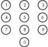 | Press to enter a channel number. |
 | Press to turn on or off the VCR. |
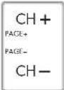 | Press to change the channel up or down. (Page not available.) |
 | Press to rewind the tape. |
 | Press to fast-forward the tape. |
 | Press to play the tape. |
 | Press to pause the tape. |
 | Press to record onto the tape. |
 | Press to stop the tape. |
 | Press to select TV/VCR as your input. |
 | Press to return to previous channel. |
DVD control buttons
The following buttons are functional after you program the DVD button with most DVD players:
| DVD button Function | |
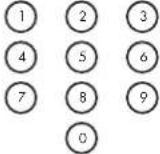 | Press to enter a chapter number. |
 | Press to turn on or off the DVD player. |
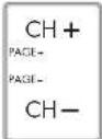 | Press CH + to go to the beginning of the next chapter. Press CH - to go to the beginning of the current chapter. |
 | Press to rewind the DVD. |
 | Press to fast-forward the DVD. |
 | Press to play the DVD. |
 | Press to pause the DVD. |
 | Press to stop the DVD. |
 | Press to open the DVD menu. |
 | Press to move the cursor around the DVD menus. |
Audio control buttons
The following buttons are functional after you program the Audio button with most audio receivers:
| Audio button Function | |
 0 0 | Press to enter a track number. |
 | Press to turn on or off the audio receiver. |
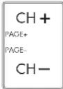 | Press CH + to go to the beginning of the next track.Press CH – to go to the beginning of the current track. |
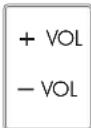 | Press to raise or lower the sound. |
| MUTE | Press to mute the sound. |
Personal Video Recorder (PVR) control buttons
The following buttons are functional after you program the PVR button with most personal video recorders:
| PVR button Function | |
| Press to enter a channel number. | |
 | Press to turn on or off the PVR. |
| Press to change the channel up or down. | |
 | Press to rewind the PVR. |
| Press to fast-forward the PVR. | |
| Press to play the DVD. | |
| Press to pause the PVR. | |
| Press to stop the PVR. | |
| Press to record with the PVR. | |
| Press to choose the highlighted selection. | |
| Press to move the cursor around the PVR menus. |
HP MCPC and HP DEC PCs
The remote control is already programmed to work with Media Center on HP MCPC and HP DEC PCs.
1 Press the HP button on the remote control to select the HP MCPC or HP DEC as the controlled device.

2 Point the remote control at the HP MCPC or HP DEC remote control sensor and press the buttons you want to use.
| Name Description Icon | ||
| Record Press Record to start recording the TV display. | ||
| Stop Press Stop to stop the recording or playback. | ||
| Skip backward Press Skip backward to go back 30 seconds in the program. | ||
| Skip forward Press Skip forward to go forward 30 seconds in the program. | ||
| Rewind Press Rewind to rewind the program or song. | ||
| Fast-forward Press Fast-forward to fast-forward the program or song. | ||
| Name Description Icon | ||
| Pause Press Pause to pause the program or song. | II | |
| Play Press Play to view the program or listen to the song. | ▶ | |
| Menu Press Menu to open Media Center. | MENU | |
| Select Press Select to choose the current menu option. | SELECT | |
| Mute | Press Mute to turn sound off or on. | MUTE |
| Info | Press Info to view information on your current program. | INFO |
| Guide | Press Guide to display the program guide. | GUIDE |
| Keypad | Press the keypad (0 – 9) to directly select channels. | 1 |
Changing the TV Settings
Change the TV settings by using the onscreen display (OSD) menus.
Using the OSD Menus
Operate the OSD menus using the buttons on the remote control to highlight, adjust, and enter items as described here.
| Remote Control Button Description | |
 | Menu: opens the onscreen display menu, or closes the menu. |
 | Direction arrow (left, up, right, down): moves to next item, or adjusts the item. |
 | Select: chooses or enters the current (highlighted) item.Note that the Select button is in the center of the direction arrow buttons. |
1 Press the Input button as needed to select the Input signal source for the TV. The OSD menus and options you see depend on the type of Input selected.
2 Open the OSD by pressing the Menu button. The available menus appear as a list.
3 Press the up or down direction arrow buttons to highlight the menu you want, then press the Select button to move to it.
4 Press the up and down direction arrow buttons to move within the menu and highlight an option, and then press the Select button to move into the option.
5 Continue using the direction arrow buttons to highlight and adjust an item, and the Select button to enter. You can press the Exit button to move out of an option, or to move up one menu level.
6 When you are finished, press the Menu button to close the menu.
The OSD menus are:
■Picture
■Audio
■Power Control
■Setup (includes EZ Setup, channel setup, and parental controls setup)
■Options
■Digital Setup (includes i.LINK)
In the following topics, a table lists each menu and the available options.
Using the Picture Menu
The Picture menu controls the look of the image on the screen for the selected input source. For example, when you adjust Brightness, the screen image changes as you adjust the scale.
Because the Picture menu maintains settings for each input, select (view) the input source, and then make Picture menu changes. The following tables show the Picture menu when an AV source is the Input, and when a PC source is the Input.
| Picture Menu (Input: AV Source) Options | |
| OPC (optical picture control) | Off/On/On:Display |
| Backlight [scale] | |
| Picture Menu (Input: AV Source) | Options |
| Contrast [scale] | |
| Brightness [scale] | |
| Color [scale] | |
| Tint [scale] | |
| Sharpness [scale] | |
| Advanced | ■C.M.S.-Hue■C.M.S.-Saturation■C.M.S.-Value■Color Temp■Black■3D-Y/C■Monochrome■Film Mode■I/P Setting |
| Reset No/Yes | |

Make sure no object obstructs the OPC sensor, which could affect its ability to sense surrounding light.
| Picture Menu (Input: PC Source) Options | |
| OPC Off/On/On:Display | |
| Backlight [scale] | |
| Contrast [scale] | |
| Brightness [scale] | |
| Red [scale] | |
| Green [scale] |
| Picture Menu(Input: PC Source) Options | |
| Blue | [scale] |
| Advanced | ■C.M.S.-Hue■C.M.S.-Saturation■C.M.S.-Value |
| Reset No/Yes |
Adjusting the picture settings
Choosing OPC
The optical picture control (OPC) adjusts the overall brightness of the screen.
With OPC set to Off, the brightness is fixed at the value set in Backlight. With OPC set to On or On:Display, the OPC sensor on the front of the TV senses the surrounding light and automatically adjusts the backlight brightness. On:Display also causes a label to appear on the screen while the OPC is adjusting the screen brightness.
Adjusting the image
These settings adjust the image you are watching, so select the correct input source before adjusting values.
■Backlight sets the overall screen brightness when OPC is off.
■Contrast sets the image contrast.
■Brightness sets the image brightness.
■Color sets the image color intensity.
■Tint sets tones; decrease to make skin tones more purple, or increase to make skin tones more green.
■Sharpness sets the image sharpness.
■ Red, Green, Blue are individual settings that control color for a PC source image.
Adjusting Advanced settings
The advanced options depend on the Input source.
C.M.S. is the color management system that manages the color tone using a scale for each of the six-color values.
■C.M.S.-Hue sets tone; decrease to make tones more red, or increase to make tones more blue.
■C.M.S.-Saturation adjusts the saturation of a selected color.
■C.M.S.-Value sets image brightness; decrease to make image darker, or increase to make image brighter.
■Color Temp sets the white balance in increments from High to Low; choose High for white with blue tones, and Low for white with red tones.
■Black sets the viewing depth automatically by adjusting the dark portion of an image; set to On for high detail in black portions of the image.
■3D-Y/C sets the response for minimal dot crawl and cross color noise for video input signals from Composite Video or Analog In. Choose Standard for normal adjustment, Fast for a movie image, or Slow for a still image.
■Monochrome sets color to monochrome for viewing video without color. Set to On for monochrome.
■Film mode automatically detects a film-based source (originally encoded at 24 frames per second), analyzes, and then recreates each still film frame for high-definition picture quality. Set to On for automatic conversion of a film source.
■I/P Setting is an image compensation setting that converts the input signal from interlace to progressive; choose Slow or Fast. The option is set to Slow when Film Mode is On; it is not selectable when the input resolution is progressive (480p or 720p).
Using Reset
To return all adjustment options to the factory preset values, highlight Reset and press Select, then highlight Yes and press Select.
Using the Audio Menu
The Audio menu sets the sound levels, and the option for the Dolby Virtual setting.
The Audio menu is not selectable when the Output Select option is set to Variable.
| Audio Menu Options | |
| Treble [scale] | |
| Bass [scale] | |
| Balance [scale] | |
| Dolby Virtual Off/On | |
| Reset Off/On | |
Adjusting the audio
In the Audio menu, select an item and adjust the scale for Treble, Base, or Balance. These options are not selectable when Dolby Virtual is set to On.
To control the audio output, including muting the speakers, refer to the Output Select option in "Using the Options Menu" on page 61.
Selecting surround sound
You can enjoy surround sound using two-channel stereo with Dolby Pro Logic II technology. To do so, select Dolby Virtual and choose On.
Virtual Dolby Digital is a technology certified by Dolby Laboratories that creates a virtualized surround sound experience from two speakers using Dolby Pro Logic or Dolby Pro Logic II.
Virtual Dolby Digital retains all the original multichannel audio information and provides the listener with the sensation of being surrounded by additional speakers.

■You can also choose Dolby Virtual by pressing the Virtual button on the remote control.
■For some discs, setup may be required on your DVD player; refer to the operation manual of your DVD player.
Using the Power Control Menu
The Power Control menu settings can save energy. The menu depends on the selected input source: an AV video source or a PC source.
| Power Control Menu | |
| AV video source Options | |
| No Signal Off Disable/Enable | |
| No Operation Off Disable/Enable | |
| PC source | |
| Power Management Off/Mode1/Mode2 |
Adjusting Power Control for an AV video source
■No Signal Off, when set to Enable, causes the TV to enter Standby Mode automatically if no signal is received for 15 minutes. When a TV program finishes, this function may not operate.
■No Operation Off, when set to Enable, causes the TV to enter Standby Mode automatically if the TV is not operated for 3 hours.
Adjusting Power Control for a PC source
The setting for Power Control for a PC source is Power Management. The options are:
■Off, the factory preset value, provides no power management.
■Mode 1 causes the TV to enter Standby Mode automatically if no signal is received for 8 minutes. The TV remains in Standby Mode even if you start using the PC and the signal returns. Turn the TV on by pressing the Power button on the TV or the remote control.
■Mode 2 causes the TV to enter Standby Mode automatically if no signal is received for 8 seconds. However, the TV turns on if you start using the PC and the signal returns.

■If using a digital PC and the Power Management setting is Mode2, the TV power may not turn back on automatically, even if the signal inputs again.
■If you turn off the power by disconnecting the AC cord when the Power Management setting is Mode2, the TV may not function properly after connecting the AC cord and turning the power on again. In such a case, turn the TV off and on again by pressing the Power button on the TV or the remote control.
Using the Setup Menu
The Setup menu options depend on the selected Input source; items appear that apply for the selected Input.
For example, Parental CTRL (used to select a secret number, and set the values for parental controls by TV rating, TV content, and movie ratings) does not appear when the selected input is Input4 (HDMI) or Input5 (DVI).
| Setup Menu Description | |
| EZ Setup Starts guided setup. | |
| CH Setup Scans for channels. | |
| Antenna Setup – Digital | Adjust for broadcast digital TV signal and channel strength. |
| Parental CTRL Enable and define parental controls for TV and movies. | |
| Position | Adjust image position on the screen for AV or PC inputs. |
| Input Signal | Manually sets image input resolution from a PC. |
| Auto Sync | Automatically adjusts the image from a PC. |
| Fine Sync Manually adjusts the image from a PC. | |
| Input Label Selects a name (from a list) for the Input source. | |
| Picture Flip Sets the orientation of the picture. | |
| Standby Mode Sets the TV mode for standby. | |
| Language Sets the OSD language. | |
Starting EZ Setup
Select EZ Setup to start the first-time setup wizard.
To start EZ Setup:
1 Press Menu on the remote control.
2 Press the Up or Down arrow buttons to highlight Setup. Press Select.
3 Highlight EZ Setup, and then press Select.
4 If you set the Secret No., enter your 4-digit secret number. See "Secret number setting for parental control (AV input mode only)" on page 65.
5 Follow the setup wizard instructions. For more information, refer to "Using the First-Time Setup Wizard" on page 29.
Using CH Setup
If the initial setup does not find all the channels, use CH Setup to manually set the antenna, scan, and find the channels.
Setting the antenna using Air/Cable option
The Air/Cable option defines what type of antenna and cable are connected to the TV analog and digital inputs.

The CATV system includes Standard, HRC, and IRC. Select the one that matches to your TV.
If channels are missing, or no channels are found after running CH Search, check your antenna connections, and then perform CH Setup again.
Scanning for channels using CH Search option
The CH Search option makes the TV look for all channels viewable from the signals connected to the TV inputs.
In the CH Search menu, highlight Yes for Analog, Digital (Air), and Digital (Cable). Then highlight Search Start and press Select; the scan automatically searches the selected inputs for channels.
Removing channels using CH Memory option
Use the CH Memory option to remove channels from the list of found channels. The removed channel does not appear when using the Channel buttons.
1 Highlight CH Memory and press Select.
2 Highlight Analog, Digital (Air), Digital (Cable), or CableCARD, and then press Select.
3 Highlight the channel and press Select.
4 Select Skip, highlight On, and press Select.
■On removes the channel.
■Off does not skip the channel.
Using Antenna Setup - Digital
In order to receive digital air broadcasts, you need a digital broadcast antenna. You can set the antenna configuration through the Antenna Setting screen. Adjust for broadcast digital TV signal and channel strength using the Antenna Setup - Digital option.
■Signal Strength shows the current and maximum signal strength.
■Channel Strength, available for Digital (Air) channels only, helps you adjust the direction of the digital broadcast antenna.
To use Channel Strength option:
1 With the Antenna set (refer to "Setting the antenna using Air/Cable" in the previous topic), view the digital broadcast channel on the TV.
2 Open the Menus and move to the Channel Strength option in the Setup/Antenna Setup - Digital menu. Press Select.
3 Move or adjust the direction of the digital broadcast antenna until you obtain the maximum signal strength. Press Select.
Using Parental CTRL
This option defines settings for Parental Control, including setting the Secret Number (Secret No.); refer to "Using Parental Controls" on page 65.
Setting Position
Use this Setup menu option to position the image on the screen by setting horizontal and vertical values. Settings depend on the Input source; this option is for AV inputs only.
Select (view) the Input before selecting the menu option and adjusting the position.
Using Input Signal
This menu option is for PC input mode only. It manually sets the image input resolution from a PC.
The pairs of input signals (resolutions) in the list below are not distinguishable when received. In such case, you have to set the correct signal manually. After setting once, it displays properly when the same signal (resolution) is input again.
| PC input resolution pairs | |
| 640 X 400 720 X 400 | |
| 640 X 480 848 X 480 | |
| 1024 X 768 1280 X 768 | |

You can select the Input Signal on the Setup menu when receiving one of the 6 input signals listed above.
Using Auto Sync
This option automatically adjusts the image from a PC.
Be sure to connect the PC to the TV and switch it on before starting Auto Sync. When Auto Sync is successful, the TV displays Completed. If not, Auto Sync failed.

■Auto Sync may fail even if "Completed" displays.
■Auto Sync may fail if the PC image has low resolution, has unclear (black) edges, or is moved while executing Auto Sync.
Using Fine Sync
This option manual adjusts the image from a PC. Ordinarily you can easily adjust the picture as necessary using Auto Sync. In some cases, however, manual adjustment is needed to optimize the image.
| Fine Sync item Description | |
| H-Pos. Centers the image by moving it to the left or right. | |
| V-Pos. Centers the image by moving it up or down. | |
| Clock Adjust when the image flickers with vertical stripes. | |
| Phase Adjust when characters have low contrast or when the image flickers. |
Setting Input Label
This option selects a name (from a list) for the Input source.

You cannot change labels for the TV or the i.LINK Input Sources.
Setting Picture Flip
This Setup option sets the orientation of the picture. Select (view) the input prior to setting the Picture Flip mode.
| Picture Flip mode Example | |
| Standard (normal image) |  |
| Mirror (mirror image) |  |
| Upside Down (upside down image) |  |
| Rotate (rotated image) |  |
Setting Standby Mode
This option sets the TV mode for standby.
Standby Mode may be set to Mode1, which starts the TV quickly from standby, or to Mode 2, which conserves energy while on standby.
To set the TV to turn off automatically to save energy, refer to "Using the Power Control Menu" on page 58.
Setting Language
This option sets the OSD language; choose English, French, or Spanish.
Using the Options Menu
The Options menu items shown depend on the Input selected.
■HDMI Setup sets options for the device connected to Input4.
| HDMI Setup Selectable items | |
| Signal Type | Auto/RGB/YCbCr 4:4:4/YCbCr 4:2:2Select the signal type from an HDMI terminal. Unless the image quality looks obviously poor, select Auto. |
| Color Matrix | Auto/ITU601/ITU709Select the internal color space conversion method when an RGB signal is input. Normally, select Auto. |
| Dynamic Range | Standard/Out of StandardSelect the signal amplitude range. Normally, select Standard. |
| Auto View | Enable/DisableSet whether or not to use VIEW MODE based on signal recognition, including an HDMI signal. |
■Audio Only, when set to On, turns the LCD display off and only audio is output. Use this setting to hear audio only when listening to music from a music program.
When listening to music from a music program, you can set the LCD display off and hear audio only.
■Digital Noise Reduction, when set it to High or Low, minimizes analog noise or interference on a analog channel.
■Input Select sets the default type of signal or connectors for the device connected to Input1, Input2, Input3, Input4, Input5.
For Input1 and Input2, you can select Auto, Component, or Video.
For Input3, you can select Auto, Video, or S-Video.
For Input4, it is set to HDMI.
For Input5, you can select Digital PC, Analog PC, Digital AV, or Analog AV. Choose Analog PC if using an RGB-to-DVI converter cable.
■Output Select selects what controls the audio output: Fixed or Variable.
Fixed, the default setting, provides a constant volume level to the Monitor Out/Rec Out terminal, and the speakers adjust using the Volume buttons.
Variable provides a volume level to the Monitor Out/Rec Out terminal controlled by the TV volume; as you adjust the TV volume, the volume level to the external system also adjusts. Speakers are muted.
■Quick Shoot, when set to On, provides a clearer image for fast-action video. If video noise occurs, set the function to Off.
■Caption Setup selects options for Closed Caption; refer to "Using Closed Caption" on page 64.
■Program Title Display, when set to No, does not show program information when you change the channel.
Using the Digital Setup Menu
This menu allows you to set image options for a digital broadcast program or digital image. The options shown depend on the Input selected.
| Digital Setup Menu Description | |
| CableCARD Menu Shows CableCARD status or messages. | |
| Video Setup | ■Screen Size■REC Picture Size |
| Digital Setup Menu Description | |
| Audio Setup Sets the Digital Audio Optical output mode. | |
| i.LINK Setup | ■i.LINK Auto Switch■Recording Mode■Standby Mode |
| Identification Shows information about the TV. | |
Using the CableCARD Menu
Use this menu to set CableCARD options or view messages. Refer to "Using a CableCARD" on page 13 to connect the digital cable and insert the CableCARD.
The item wording in the CableCARD menu depends on the manufacturer of the CableCARD.
If there is a white triangle at the right side of the screen, the screen is not showing the entire message. Press the direction arrow buttons on your remote control to display the rest of the message.
When there is a LINK button on the screen, there is a link to the next page. Press Select on the remote control to go to the next page.
Using the Video Setup
■Screen Size sets the format of a digital broadcasting image.
| Screen Size Description | |
| Manual | With 480i/480p/720p broadcasts, you can change the screen size to the size of your choice. |
| Auto | All broadcasts are converted and displayed in the 1080i format. |
■REC Picture Size sets the screen size to record on 16:9 video.
| REC Picture Size Description | |
| 4:3 TV Bars may appear on the top and bottom with some programs. | |
| 16:9 TV Displays in full screen. | |
Using Audio Setup
The TV provides digital audio output for an AV amplifier or similar device connected to the DIGITAL AUDIO OUTPUT terminal on the TV. Select an audio output format compatible with the audio format of the program you are watching and the connected equipment.
| Audio SetupMenu Description | |
| PCM The optical output terminal outputs audio signal in PCM form. Choose this option when your digital audio system does not support Dolby Digital, or when the source is analog, such as from an analog channel. | |
| Dolby Digital The optical output terminal outputs audio signal in Dolby Digital form from digital programming. | |
Using the i.LINK Setup
■i.LINK Auto Switch, see "Automatic input switching to i.LINK" on page 41.
■Recording Mode, see "Setting the recording mode (i.LINK)" on page 37.
■Standby Mode, see "Setting the standby mode (i.LINK)" on page 37.
Viewing TV Identification information
This menu shows information about the TV.
Selecting the view aspect
For non-tuner input sources, select how the picture appears by choosing the aspect option. You use this menu by pressing View Mode button on the remote control to change the dimensions of your display image. Your options depend on what is currently viewed.
■Side Bar – shows the standard 4:3 ratio picture image in the center of the TV with dark bars on the left and right.

■Smart Stretch (S.Stretch) – horizontally stretches the TV picture, if necessary, to fill the screen. Suitable for stretching normal 4:3 programs to fill the screen.
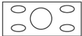
■Zoom – proportionally stretches the TV picture, but clips the top and bottom of the image to fit the screen. Eliminates black bars.

■Stretch – shows High-definition TV in its normal format.
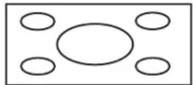
- Dot by Dot – detects the resolution of the signal and displays an image with the same number of pixels on the screen. This mode is available for High-definition programs only.

When using Dot by Dot, it is possible to see noise or bars around different outer portions of the screen. Change the view mode to correct this.
Using Closed Caption
Your TV is equipped with an internal Closed Caption decoder. It allows you to view conversations, narration and sound effects as subtitles on your TV. Closed Captions are available on some TV programs, and on some VHS home video tapes, at the election of the program provider.
Digital Closed Caption service is a caption service available only on digital TV programs (also at the election of the service provider). It is a more flexible system than the original Closed Caption system, because it allows a variety of caption sizes and font styles. When the Digital Closed Caption service is in use, it is indicated by a 3-letter abbreviation that also indicates the language of the Digital Closed Captions: ENG (English) or SPA (Spanish) or FRA (French), or other language codes.
Not all programs and VHS videotapes offer closed caption. Look for the symbol to ensure that captions appear.
In the Closed Caption system, there can be more than one caption service provided. Each is identified by its own number. CC1 and CC2 services display subtitles of TV programs superimposed over the program picture.
In the Closed Caption system, the Text1 or Text2 services display text that is unrelated to the program being viewed, such as weather or news. These services are also superimposed over the program currently being viewed.
■Depending on the number of caption services in the signal being received, you will see information such as 1/2 or 1/4 displayed. 1/2 means "the first of two services."
■Example: If a program has three services (Digital CC(ENG), CC1 and Text1), the closed caption display toggles in sequence.
■The CC button keeps a record of the last service selected in its memory.
If the last closed caption mode you selected is not available for the next program, or on another channel, the closed caption service that is available is automatically selected, and this service appears in parentheses.
Closed caption services that appear in parentheses is not retained in the CC button memory as your last selected service. Only services that you have selected with the CC button are retained.

When the program contains no closed caption, "--" displays in the closed caption information.
If the language code, such as ENG, is not found on Digital TV programs, "--" is shown.
Four kinds of closed caption service (CC1, CC2, Text1, Text2) are potentially available, but a broadcast may contain none, or only some of these services, at the election of the program provider.
The defaults for CC may be specified by broadcasting station.
■Caption Size selects a caption size.
■Font Style selects a font style.
| Font Style | Description |
| Default The font specified by broadcasting station or default font. | |
| Type 0 Proportional font used in the MENU screen. | |
| Type 1 Monospaced with serifs. | |
| Type 2 Proportionally spaced with serifs. | |
| Font Style | Description (Continued) |
| Type 3 Monospaced without serifs. | |
| Type 4 Proportionally spaced without serifs. | |
| Type 5 Casual font type. | |
| Type 6 Cursive font type. | |
| Type 7 Small capitals. | |
■Foreground Color selects a character foreground color.
■Foreground Opacity selects a foreground opacity value.
■Background Color selects a character background color.
■Background Opacity selects a background opacity value.
■Character Edge selects a character edge.
Using Parental Controls
Secret number setting for parental control (AV input mode only)
Allows you to use a secret number to protect certain settings from being accidentally changed.

IMPORTANT: Three conditions must be met to enable V-Chip parental controls:
■Secret No. is registered.
■V-Chip settings have been made.
■Parental Control Status is set to On.
Setting a secret number
In the Setup Menu, select Parental CTRL, Secret No., and then enter the new 4-digit secret number by using the 0–9 buttons on the remote control. Enter the same digits for Reconfirm and then press Select.

IMPORTANT: As a precautionary measure, record your secret number. See "Recording your secret number" on page 83.
Setting parental control status
Status is used to enable or disable the parental control function. Select On to enable and Off to disable Parental CTRL.

IMPORTANT: If the TV is forced-tuned to a channel that has been blocked by Parental Control, the Parental Control setting is given priority, and the EAS message is not broadcast.
Changing the secret number
New Secret No. in the Secret No. menu allows you to change your current secret number.
Clearing the secret number
Secret No. Clear in the Secret No. menu allows you to clear your secret number.

As a precautionary measure, make a note of your secret number and keep it in a familiar place. If you lose or forget your secret number, initialize the television to return all settings except for the TV channel settings to factory preset values. (See "Returning to Factory Presets" on page 69.)
If the secret number is cleared, the Status setting automatically sets to Off. V-Chip and Status are not selectable from the menu.
Setting Parental Control V-Chip level
V-Chip is an electronic filtering device built into your TV. This tool gives parents a great degree of control over broadcasts accessed by their children. It allows
parents to select programs judged suitable for child viewing while blocking ones judged not suitable. It does so automatically once you activate the V-Chip feature in your television.
V-Chip and Status are not selectable from the menu if you do not first configure your secret number.
■The U.S. has two rating systems for viewing content: TV Parental Guidelines and movie ratings.
■The TV Parental Guidelines work in conjunction with the V-CHIP to help parents screen out inappropriate television shows from their children.
■Movie ratings are used for original movies rated by the Motion Picture Association of America (MPAA) as watched on cable TV and not edited for television. The V-Chip can also be set to block MPAA-rated movies.
Voluntary movie rating system (MPAA)
| Rating | Description | |
| Age G | General audiences. All ages admitted. | |
| PG Parental guidance suggested. Some material may not be suitable for children. | ||
| PG-13 | Parents strongly cautioned. Some material may be inappropriate for children under 13. | |
| R | Restricted. Under 17 requires accompanying parent or adult guardian (age varies in some jurisdictions). | |
| NC-17 No one 17 and under admitted. | ||
| X | X is an older rating that is unified with NC-17 but may be encoded in the data of older movies. | |
Example:
If you select PG-13, this automatically blocks the higher ratings R, NC-17, and X.

Voluntary movie rating system only uses an age-based rating.
TV Parental Guidelines
| Rating | Content | |||||
| FV (Fantasy Violence) | V (Violence) | S (Sexual Situation) | L (Adult Language) | D (Sexually suggestive dialog) | ||
| Suggested Age | TV-Y (All Children) | |||||
| TV-Y7 (Directed to older children) | Rating can be set | |||||
| TV-G (General Audience) | ||||||
| TV-PG (Parental Guidance suggested) | Rating can be set | Rating can be set | Rating can be set | Rating can be set | ||
| TV-14 (Parents strongly cautioned) | Rating can be set | Rating can be set | Rating can be set | Rating can be set | ||
| TV-MA (Mature audience only) | Rating can be set | Rating can be set | Rating can be set | |||
Voluntary movie rating system (MPAA)
Select V-Chip in the Parental CTRL menu and press Select. Then highlight MPAA and press Select. Adjust the item.
The setting automatically enters Block for any ratings below your selection.
TV Parental Guidelines (TV Guidelines)
Repeat steps in Voluntary movie rating system (MPAA), select TV Guidelines and then press Select. Adjust the item.
The setting automatically enters Block for any ratings below your selection.
You can set an individual content-based rating item.
Canadian Rating Systems
The TV rating systems in Canada are based on the Canadian Radio-Television and Telecommunications Commission (CRTC) policy on violence in television programming.
While violence is the most important content element to be rated, the structure developed takes into consideration other program content like language, nudity, sexuality and mature themes.
When setting the V-Chip on the Canadian system you can choose either the Canadian English ratings or the Canadian French ratings.
Canadian English ratings
| Rating Canadian English rating Description | ||
| Age | E | Exempt: Includes news, sports, documentaries and other information programming; talk shows, music videos, and variety programming. |
| C | Children: Intended for younger children under the age of 8 years. Pays careful attention to themes that could threaten their sense of security and well-being. | |
| C8+ | Children over 8 years old: Contains no portrayal of violence as the preferred, acceptable, or only way to resolve conflict; nor encourage children to imitate dangerous acts which they may see on the screen. | |
| G | General: Considered acceptable for all age groups. Appropriate viewing for the entire family, contains very little violence—physical, verbal, or emotional. | |
| PG | Parental Guidance: Intended for a general audience, but may not be suitable for younger children (under the age of 8) because it could contain controversial themes or issues. | |
| 14+ | Over 14 Years: Could contain themes where violence is one of the dominant elements of the storyline, but it must be integral to the development of plot or character. Language usage could be profane and nudity present within the context of the theme. | |
| 18+ | Adults: Intended for viewers 18 years and older and might contain depictions of violence, which while related to the development of plot, character, or themes, are intended for adult viewing. Could contain graphic language and portrayals of sex and nudity. | |
Canadian French ratings
| Rating Canadian French ratings Description | |
| Age E | Exempt programming. |
| G General: All ages and children, contains minimal direct violence, but may be integrated into the plot in a humorous or unrealistic manner. | |
| 8anse+ General but inadvisable for young children: May be viewed by a wide public audience, but could contain scenes disturbing to children under 8 who cannot distinguish between imaginary and real situations. Recommended for viewing with parent. | |
| 13anse+ Over 13 years: Could contain frequent violent scenes and therefore recommended for viewing with parent. | |
| 16anse+ Over 16 years: Could contain frequent violent scenes and intense violence. | |
| 18anse+ Over 18 years: Only for adult viewing. Could contain frequent violent scenes and extreme violence. | |
How to temporarily release the V-Chip BLOCK
When the V-Chip is working and censors a broadcast, a message displays: V-CHIP HAS BEEN ACTIVATED.
1 Press Select while the V-Chip is working and then the secret number setting menu displays.
2 Enter your 4-digit secret number with 0–9. At this time V-CHIP BLOCK temporarily releases.
Reactivating the temporarily released V-Chip BLOCK
You can reactivate the temporarily released V-CHIP BLOCK as shown below.
Method 1:
Select Status setting from the Parental CTRL menu to reactivate BLOCK.
Method 2:
Select V-Chip setting (MPAA, TV Guidelines, Can. English Ratings, or Can. French Ratings) from the Parental CTRL to reactivate BLOCK.
Method 3:
Switch off the TV power.

Performing any of the three methods above activates the V-CHIP BLOCK.
Returning to Factory Presets
Use this procedure to set all items (except TV channel) to return to the factory presetting.
1 Check that the power indicator is not on. If necessary turn off the TV.
2 Remove the AC cord.
3 Press and hold down RESET (A) at the same time as you re-insert the AC Cord into the outlet and switch on the TV.

Running the factory presetting operation also clears the secret number.
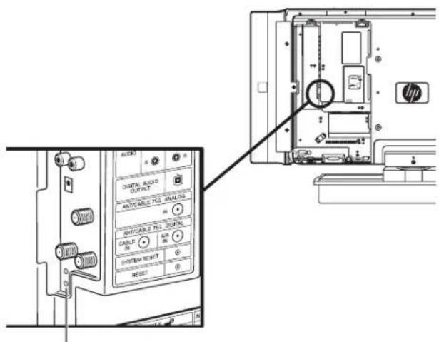
A
A: Reset button
Finding Answers to Questions
Understanding TV Terms
What are Analog TV, Digital TV, and high-definition (HDTV)?
Devices such as monitors, tuners, and integrated monitor/tuner combinations designed to handle any of the 18 formats officially sanctioned by the industry-led standard setting, Advanced Television Systems Committee (ATSC), for the digital transmission of video signals. There are three subgroups of digital televisions depending on their capabilities: high-definition (HDTV), enhanced-definition (EDTV), and standard-definition (SDTV).
In contrast, US analog television has been available for over 50 years in the single National Television Standards Committee (NTSC) format. This is the signal that has been broadcast over the air and through cable systems. NTSC television offers slightly more than 480 interlaced lines of resolution.
What is the difference between progressive and interlaced signal formats for digital TVs?
There are 18 standard digital TV signal formats. Each one provides a different picture quality. Digital TV formats are named using a number followed by either progressive (p) or interlaced (i). The letter refers to the way the TV uses the signals to create the picture:
■Progressive (p) scanning presents all the horizontal lines of the picture in one frame. This provides a sharper picture to the eye and looks much better than an interlaced image of the same resolution.
■Interlaced (i) means that the picture appears in two segments: every other horizontal line of the picture is displayed in one frame, and the other half of the horizontal lines are drawn in the next frame of the picture. This works because it happens so fast that the eye is deceived into believing that only one picture is being shown.
The number refers to the number of lines of resolution, and generally the higher the number, the better the picture. For example, with digital TV (DTV) there are two progressive formats for broadcasters to choose from: 480p and 720p. A 480p image is much sharper than a regular TV broadcast, although it is only considered a DTV signal and not a true high-definition signal. 720p has 720 horizontal scan lines and is considered to be true HDTV. 720p can rival a 1080i picture, which is 1080 horizontal scan lines displayed as an interlaced image. This is because of the sharper and more accurate (progressive) 720p picture, even though 1080i picture has many more scan lines and a much higher resolution.
What is variable aspect ratio?
The aspect ratio describes the relationship of screen width to screen height. Standard TV signals are based on the aspect ratio of 4:3 (four units wide by three units high). HDTV signals are based on the aspect ratio of 16:9, making the image 33 percent wider than a normal TV and allowing viewing TV and movies as if you were watching them in a theater.
In addition, many DVDs look better on the widescreen display because most movies made in the last 50 years were filmed in an aspect ratio of either 1.85:1 (very close to 16:9, which is equal to 1.78:1) or 2.35:1 (even wider than 16:9).
Variable aspect ratio support enables scaling of 4:3 and anamorphic video to fill the screen.
What is HDMI?
High-Definition Multimedia Interface (HDMI) is the first industry-supported, uncompressed, all-digital audio/video interface. HDMI components can transmit both digital audio and video over a single cable with improved quality over traditional analog connections due to an all-digital transmission. Transferring digital sources to display such as DVDs and HDTV programming can now be done without analog conversions that can degrade the original signal.
What is CableCARD, and how does it work?
HP HDTVs with CableCARD (certain countries/regions only) slots can accept a small card from your cable company that allows you to receive standard-definition and high-definition digital broadcasts without the need
for a set-top box. When a CableCARD is inserted into the television, it enables delivery of digital video programming and other services. CableCARDs are provided directly by the cable operator to customers who request them. CableCARD functionality includes copy protection and signal demodulation.
Identifying Cable Usage
The following section lists all of the cable types available for the TV. It shows a side view of each with its respective connector.
| Cable type/connection Description | |
RCA(D37C)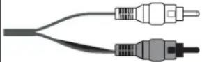 | Red and white audio connectors connect to the red and white (L & R) audio inputs. |
Digital audio(C348) | High-resolution optical audio cables used for optional external audio system. |
HDMI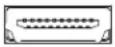  | HDMI is capable of transmitting both uncompressed digital audio and digital video signals because it has video, audio, and control signals. |
i.LINK cable4-Pin  | 4-pin is generally used for Blu-ray, D-VHS, and AV-HDD to the TV i.LINK port. |
| Cable type/connection Description | (Continued) |
Coaxial antenna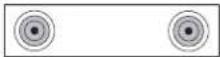 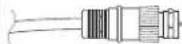 | RF or coaxial used mainly for antennas. Often used with cable TV, a cable or satellite decoder. May be used with set-top boxes if no other choice is available. Cable plugs into air and cable RF jacks. |
S-video 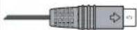 | Used with equipment such as DVD players, VCRs, cable or satellite tuner/decoders, camcorders, and digital cable boxes. Cable plugs into S-video output. |
Power cord  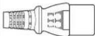 | Connects the TV to the power outlet. |
Composite 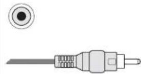 | Used with equipment such as a VCR or DVD. Cable plugs into AV input or output. |
Component   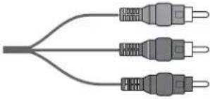 | Three- or five-headed cable: One red for Pr signal, one green for Y signal, and one blue for Pb signal. Some component cables also come with red and white audio cables attached. Used for HDTV receivers, DVD players, and other devices equipped with a YPbPr component output connector. |
DVI-I Digital Video Interface often used with PCs, set-top boxes, and DVDs.[x6y2]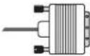 | |
RS-232 Serial interface used for industrial control applications.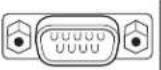 |
Specifications
HP LC3700N 37-inch (94-Centimeter) LCD High-Definition Television HP LC3200N 32-inch (81-Centimeter) LCD High-Definition Television HP LC2600N 26-inch (66-Centimeter) LCD High-Definition Television
| Display | |
| LCD panel HP LC3700N: 37 in. Advanced Super View & Black TFT LCDHP LC3200N: 32 in. Advanced Super View & Black TFT LCDHP LC2600N: 26 in. Advanced Super View & Black TFT LCD | |
| Dimensions with stand and speakers (h x w x d) | HP LC3700N: 25.5 in. (64.8 cm) x 46.5 in. (118.1 cm) x 12 in. (30.5 cm)HP LC3200N: 22.9 in. (58.1 cm) x 41.9 in. (106.3 cm) x 12 in. (30.5 cm)HP LC2600N: 19.9 in. (50.5 cm) x 36.8 in. (93.4 cm) x 10.8 in. (27.5 cm) |
| Dimensions without stand and with speakers (h x w x d) | HP LC3700N: 22.3 in. (56.7 cm) x 46.5 in. (118.1 cm) x 4.3 in. (10.9 cm)HP LC3200N: 19.6 in. (49.9 cm) x 41.9 in. (106.3 cm) x 4.3 in. (10.9 cm)HP LC2600N: 16.7 in. (42.5 cm) x 36.8 in. (93.4 cm) x 4.25 in. (10.8 cm) |
| Number of dots Up to 3,147,264 dots (1366 x 768 x 3 dots) | |
| Brightness | Up to 450 cd/m2 |
| Backlight life Up to 60,000 hours (at viewing angles | backlight standard position)H: 170° V: 170° |
| Audio out 10 W x 2 | |
| OSD language English/French/Spanish | |
| Power requirement | AC 120 V 260 Hz |
| Power consumption HP LC3700N: 195 WHP LC3200N:155 WHP LC2600N: 130 W | |
| Ventilation clearance requirements 1.4 in. (3.5 cm) rear | |
| TV Function | |
| TV standard (CCIR) American TV Standard ATSC/NTSC system | |
| Receiving channel VHF: 2 – 13 | UHF: 14 – 69CATV: 1 – 125Digital Terrestrial Broadcast (8VSB): 2 – 69Digital cable (64/256 QAM): 1 – 135 |
| Audio multiplex BTSC system | |
| Rear Terminals | |
| Input 1 AV In, Component In | |
| Input 2 AV In, Component In | |
| Input 3 S-video In, AV In | |
| Input 4 HDMI In (Type-A) with HDCP | |
| Input 5 Audio In, DVI-I In with HDCP | |
| Analog antenna 75-ohm Unbalance, F Type for VHF/UHF/CATV in x 1 | |
| Digital antenna 75-ohm Unbalance, F Type x 2 (for Digital Air x 1/Digital Cable In x 1) | |
| Monitor/Rec Out S-video Out, AV Out | |
| Digital audio output Optical Digital audio output x 1 (PCM/Dolby Digital) | |
| i.LINK IEEE 1394 x 2 with DTCP | |
| CableCARD slot 68 pin PCMCIA x 1 | |
| Weight | |
| TV only HP LC3700N: 40.8 lb. (18.5 kg) | HP LC3200N: 34.2 lb. (15.5 kg)HP LC2600N: 25.4 lb. (11.5 kg) |
| TV with speakers (no stand) HP LC3700N: 48.5 lb. (22 kg) | HP LC3200N: 40.8 lb. (18.5 kg)HP LC2600N: 32 lb. (14.5 kg) |
| TV with speakers and stand HP LC3700N: 59.5 lb. (27 kg) | HP LC3200N: 52.9 lb. (24 kg)HP LC2600N: 39.7 lb. (18 kg) |
| Accessories | |
| In the box Documentation, Remote control | unit, AC cord, Cable clamp (select models only), Cable tie |
| Recommended solution additions HP Digital Entertainment Center | HP Media Center PCHP Media Center Extender |
| Certification and Compliance | UL, C-UL, FCC, BETS-7 |
| Warranty | 1 year, parts and labor |
All specifications represent the typical specifications provided by HP's component manufacturers; actual performance may vary either higher or lower.
PC Compatibility Chart
| PC/Mac Resolution | Horizontal Frequency | Vertical Frequency | VESA Standard | ||
| PC VGA 640 x | 400 31.5 kHz | 60 Hz | |||
| 37.9 kHz 85 Hz O | |||||
| 720 x 400 31.5 kHz 60 Hz | |||||
| 37.9 kHz 85 Hz O | |||||
| 640 x 480 31.5 kHz 60 Hz O | |||||
| 37.9 kHz 72 Hz O | |||||
| 37.5 kHz 75 Hz O | |||||
| 43.3 kHz 85 Hz O | |||||
| WVGA 848 | x 480 31.5 kHz 60 Hz | ||||
| SVGA 800 | x 600 35.1 kHz 56 Hz O | ||||
| 37.9 kHz 60 Hz O | |||||
| 48.1 kHz 72 Hz O | |||||
| 46.9 kHz 75 Hz O | |||||
| 53.7 kHz 85 Hz O | |||||
| XGA 1024 | x 768 48.4 kHz 60 Hz O | ||||
| 56.5 kHz 70 Hz O | |||||
| 60.0 kHz 75 Hz O | |||||
| 68.7 kHz 85 Hz O | |||||
| WXGA 1280 | x 720 45.0 kHz 60 Hz | ||||
| 1280 x 768 48.1 kHz 60 Hz | |||||
| SXGA 1280 | x 1024 64.0 kHz 60 Hz O | ||||
| Mac 13" VGA | 640 x 480 34 | 9 kHz 67 Hz | |||
| Mac 16" SVGA | 832 x 624 49 | 7 kHz 75 Hz | |||
| Mac 19" XGA | 1024 x 768 60 | 2 kHz 75 Hz | |||
RS-232C Port Specifications
PC control of the TV
When a program is set, the TV can be controlled from the PC using the RS-232C terminal. The input signal (PC/AV) can be selected, the volume can be adjusted and various other adjustments and settings can be made, enabling automatic programmed playing. Attach an RS-232C cable cross-type (sold separately) to the supplied Din/D-Sub RS-232C for the connections.

This operation system should be used by a person who is accustomed to using PCs.
Communication conditions
Set the RS-232C communications settings on the PC to match the TV's communications conditions.
The TV's communications settings are as follows:
| Baud rate: 9,600 bps | |
| Data length: 8 bits | |
| Parity bit: None | |
| Stop bit: 1 bit | |
| Flow control: None |
Communication procedure
Send the control commands from the PC with the RS-232C connector. The TV operates according to the received command and sends a response message to the PC. Do not send multiple commands at the same time. Wait until the PC receives the OK response before sending the next command.
Command format
Eight ASCII codes + CR
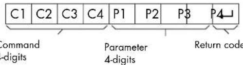
Command 4-digits: Command. The text of four characters.
Parameter 4-digits: Parameter 0–9, x, blank, ?
Parameter
Input the parameter values, aligning left, and fill with blank(s) for the remainder. (Be sure that 4 values are input for the parameter.) When the input parameter is not within an adjustable range, ERR returns. (Refer to "Response code format.") Any numerical value can replace the x on the table.
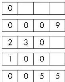
When ? is input for some commands, the present setting value responds.
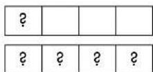
Response code format
Normal response
Return code (ODH)
Problem response
(communication error or incorrect command)
Return code (ODH)
Troubleshooting
Refer to this section if you have viewing, picture, sound, remote, or startup problems with your TV.
Startup questions
| Symptom Remedy | |
| I do not hear sound at power on. | ■Are the two speaker wires connected at the speaker and on the TV, and■Is the volume too low?■Is Variable selected in Output Select? |
| I do not see an image at power on. | ■Are the connections to other components correct?■Is the correct input signal source selected after connection?■Is the correct input selected?■Is a non-compatible signal being input?■Is the picture adjustment correct?■Is On selected in Audio Only?If, after inserting the CableCARD, you are unable to receive broadcast service, remove the CableCARD and reinsert. |
| There is no power. | ■Check whether you pressed Power button on the remote control unit.■If the indicator on the TV is off, press Power on the TV.■Is the AC cord disconnected? |
| The unit cannot be operated. | ■External influences such as lightning and static electricity may cause improper operation. In this case, operate the unit after first turning on the power of the TV or unplugging the AC cord and replugging it in after 1 or 2 minutes. |
| The color is strange, faded, or misaligned. | ■Adjust the picture tone.■Is the room too bright? The picture may look dark in a room that is too bright.■Check the input signal setting. |
| The power suddenly turned off. | ■Is the sleep timer set?■Check the power control settings.■The unit's internal temperature has increased.■Remove any objects blocking vent or clean the vent. |
| Upgrade is displayed continuously. | ■Verify your antenna cable is connected properly.■Reinsert the CableCARD. If the trouble still exists after reinserting the CableCARD and verifying the antenna cable, contact your local cable provider company. |
Viewing questions
| Symptom Remedy | |
| I get a poor picture with video signal input. | Check the following: Improper control setting. Local interference.Cable interconnections. Adjust picture control as needed. Try another location for the TV. Be sure that all connections are secure. |
| I get a poor picture with DVI signal input. | Check the following: Improper control setting. Incorrect pin connections on the connector. Adjust picture controls as needed. |
| Nothing appears on the screen, and I have an external device controlling the TV. | ■Press the Input button on the remote control and confirm the source is selected.■Verify that the external device or PC power is turned on.■Check to see whether the source component is connected.■Check the power management function. Is it in standby mode?■Connect the source to the TV. Operate the external device or PC (move the mouse, or press a key). |
Picture quality questions
| Symptom Remedy | |
| Part of my picture is cut off, or the picture is not centered. | Check the position adjustment settings, and adjust the screen settings accordingly. |
| My picture image is too large or too small. | Press the Aspect button on the remote control, and adjust properly. |
| My picture is unstable. Verify that the external device or PC resolution setting is correct. Adjust to the appropriate resolution. | |
| There are bright spots on my LCD screen. | In some cases, an LCD panel may have pixels that do not operate properly. This is common to all LCD displays used in products supplied by all vendors and is not specific to this product. |
Remote control questions
| Symptom Remedy | |
| The remote control does not work. Check the following, and try the proposed solution:■Press the TV button to control the TV.■Batteries are inserted with polarity aligned.■Make sure the remote control batteries are fresh. If they are worn out, replace the batteries with three (3) new AAA alkaline batteries.■Make sure the remote control is within correct operating range.■Make sure the remote sensor window is not under too much light, direct sunlight, or strong artificial light.■Make sure there are no obstacles; check that there is nothing between the remote control and the sensor window on the display. | |
| Symptom Remedy | |
| A red light blinks when I press a key, but my home entertainment equipment does not respond. | Make sure the remote control is aimed at your home entertainment equipment and is not farther than 16.4 feet (5 meters) away. |
| The selected mode button (TV, DVD, STB, PVR, Aux, VCR, Audio, or HP) does not blink when a button on the remote control is pressed. | Replace the batteries with three (3) AAA non-rechargeable batteries. |
Remote control programming questions
| Symptom Remedy | |
| The remote control does not control home entertainment equipment, or the commands are not working properly. | Try all listed codes for the equipment brands being set up. Make sure they can be operated with an infrared remote control. |
| Changing channels does not work properly. | If the original remote control required pressing Select to change channels, press Enter on the remote control after entering the channel number. |
| CH +, and CH – do not work for your RCA TV. | Due to RCA design (1983–1987), only the original remote control operate these functions. |
Broadcast reception error messages
| Error Message | Error code Possible Solution |
| Failed to receive broadcast. E202 Check the antenna cable. Check that the antenna is correctly set up. | |
| No broadcast now. E203 Check the broadcast time in the program guide. | |
i.LINK cautions
| Caution Sentence Possible Solution | |
| Record/playback may fail on the selected model. | Displayed when you have selected a device that is not compatible with the TV or that does not have DTLA copy protection technology installed. |
| Wrong connection or no i.LINK connection was found. Refer to User's Guide on connection. | Displayed when a problem is experienced with a connection using i.LINK cable. Check the connection, and reconnect the cable if necessary. |
| The selected model is disabled to record/play. Check that no other model is used. | Displayed when the device you have selected is already being used by another i.LINK connected device. To operate the selected device from the TV, you will first have to override control from the other device. |
FCC Notice
Federal Communications Commission Notice
This equipment has been tested and found to comply with the limits for a Class B digital device, pursuant to Part 15 of the FCC Rules. These limits are designed to provide reasonable protection against harmful interference in a residential installation. This equipment generates, uses, and can radiate radio frequency energy and, if not installed and used in accordance with the instructions, may cause harmful interference to radio communications. However, there is no guarantee that interference will not occur in a particular installation. If this equipment does cause harmful interference to radio or television reception, which can be determined by turning the equipment off and on, the user is encouraged to try to correct the interference with one or more of the following measures:
■Reorient or relocate the receiving antenna.
■Increase the separation between the equipment and receiver.
■Connect the equipment into an outlet on a circuit different from that to which the receiver is connected.
■Consult the dealer or an experienced radio or television technician for help.
This television receiver provides display of television closed captioning in accordance with 15.119 of the FCC Rules.
Closed caption notice (fcc 15.119 rules)
Modifications
The FCC requires the user to be notified that any changes or modifications made to this device that are not expressly approved by Hewlett-Packard Company may void the authority to operate the equipment.
Cables
Connections to this device must be made with shielded cables with metallic RFI/EMI connector hoods in order to maintain compliance with FCC Rules and Regulations.
Recording your secret number

As a precautionary measure, make a note of your secret number below, cut it out of this manual, and keep it in a familiar place.
Copyright © 2005 Hewlett-Packard Development Company, L.P.
Digital TV Solutions
Attn: Product Regulations Manager
10435 N. Tantau Avenue
CAC 07, MS 4295
Cupertino, CA 95014 USA
http://www.hp.com/recycle
natural_image
Technical diagram of a mechanical assembly with labeled component 'c' (no text or symbols beyond label)natural_image
Simple line drawing of a monitor with an arrow pointing to its screen (no text or symbols)natural_image
Technical line drawing of a computer monitor base with labeled components and mounting bracket (no text or symbols present)natural_image
Technical line drawing of an electronic device chassis with mounting bracket and internal components (no text or symbols)Installation du support
natural_image
Technical line drawing of a computer chassis with an open lid and internal components (no text or symbols)natural_image
Technical line drawing of an open computer case with internal components and connectors (no text or symbols)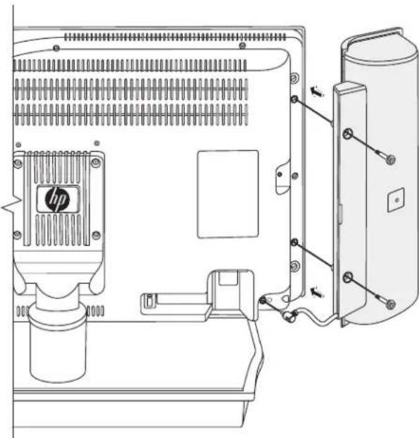
natural_image
Technical line drawing of a mechanical assembly with labeled components (no text or symbols)Précautions relatives au raccordement i.LINK
A
A : Touche RESET
Conditions de communication
Copyright © 2005 Hewlett-Packard Development Company, L.P.
ENTIDAD RESPONSABLE:
Hewlett-Packard Company
Digital TV Solutions
Attn: Product Regulations Manager
10435 N. Tantau Avenue
CAC 07, MS 4295
http://www.hp.com/recycle
natural_image
Technical diagram of a mechanical assembly with labeled component C (no text or symbols present)natural_image
Simple line drawing of a monitor with an upward arrow and a downward arrow, no text or symbols present.natural_image
Technical line drawing of a computer monitor with labeled components and mounting base (no text or symbols present)natural_image
Technical line drawing of a computer chassis with an open lid and internal components (no text or symbols)natural_image
Technical line drawing of a computer chassis with ventilation slots and mounting bracket (no text or symbols)natural_image
Technical line drawing of a computer tower internal structure with no visible text or symbols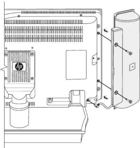
natural_image
Technical line drawing of a mechanical assembly with labeled components (no text or symbols)A: Cable coaxial de 75 ohmios (redondo)
B: Cable bifilar de 300 ohmios (plano)
C: Conector tipo F
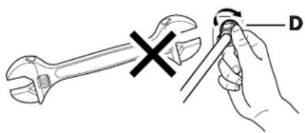
A: Botón Restaurar