
DE6256 - Drilling template DEWALT - Free user manual and instructions
Find the device manual for free DE6256 DEWALT in PDF.

| Brand | DeWalt |
| Model | DE6256 |
| Product type | Drilling jig for dowel joints |
| Compatible dowel diameters | 6 mm, 8 mm, 10 mm |
| Workpiece thickness | 12 - 30 mm |
| Guide bushing diameter | 11 mm |
| Weight | 2.3 kg |
| Package contents | Jig, 14 mm guide bushings (x2), screws, positioning pins (6, 8, 10 mm), plastic cams, screw-in studs, spring anchor assemblies, manual, exploded drawing |
| Compatible routers | DeWalt DW613, DW620, DW621, DW625, DW626, Elu MOF96(E), MOF177(E) |
| Main functions | Professional dowel joint creation, automatic centering, drilling blind and through holes, edge and center doweling |
| Maintenance and lubrication | No lubrication required |
| Warranty | 30-day satisfaction guarantee, 1 year free maintenance, 1 year parts and labor warranty |
| Safety instructions | Wear safety glasses, appropriate clothing, keep work area clean, use the tool as intended |
| Repairability | Repair exclusively by a DeWalt authorized service center |
Frequently Asked Questions - DE6256 DEWALT
User questions about DE6256 DEWALT
0 question about this device. Answer the ones you know or ask your own.
Ask a new question about this device
Download the instructions for your Drilling template in PDF format for free! Find your manual DE6256 - DEWALT and take your electronic device back in hand. On this page are published all the documents necessary for the use of your device. DE6256 by DEWALT.
USER MANUAL DE6256 DEWALT
natural_image
Technical line drawing of a rectangular mechanical component with coiled spring and mounting flanges (no text or symbols)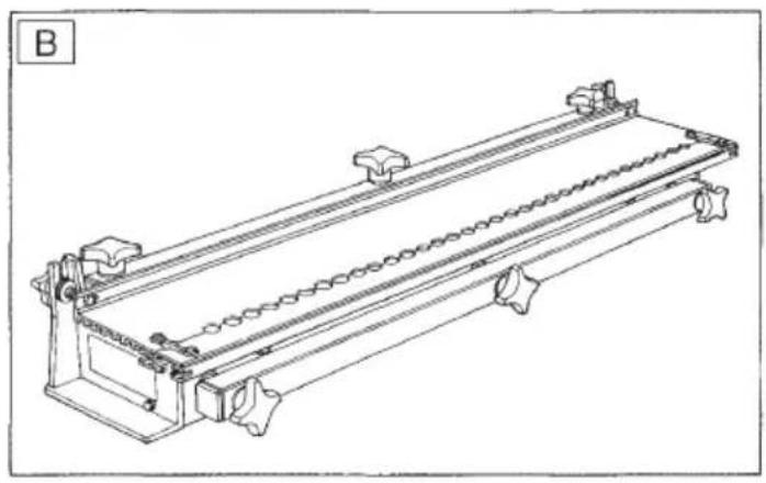
natural_image
Technical line drawing of a mechanical conveyor system with rollers and supports (no text or symbols)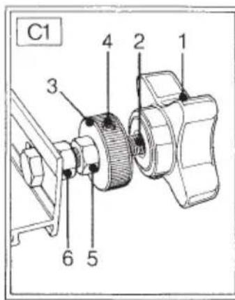
FORDYVLINGSSKABELON DE6256
Tillykke!
You have chosen a DEWALT product. Years of experience, thorough product development and innovation make DEWALT one of the most reliable partners for professional users.
Table of contents
| Technical data en - 1 |
| Manufacturer's declaration en - 1 |
| Safety instructions en - 2 |
| Package contents en - 2 |
| Description en - 2 |
| Assembly and adjustment en - 2 |
| Instructions for use en - 4 |
| Maintenance en - 4 |
| Guarantee en - 5 |
Technical data
| DE6256 | |
| Dowel size mm 6, 8, 10 | |
| Workpiece thickness mm 12 - 30 | |
| Guide bush size mm 11 | |
| Weight kg 2.3 | |
The following symbols are used throughout this manual:

Denotes risk of personal injury, loss of life or damage to the tool in case of non-observance of the instructions in this manual.
Manufacturer's declaration

DE6256
DEWALT declares that this unit has been designed in compliance with 89/392/EEC.
This unit must not be put into service until it was established that the Power Tool to be connected to this unit is in compliance with 89/392/EEC (identified by the CE-marking on the Power Tool).
Director Engineering and Product Development Horst Großmann
X. fopman
Observe the safety regulations in the instruction manual of the Power Tool to be connected to this attachment. Also observe any applicable additional safety rules. Read the following safety instructions before attempting to operate this product. Keep these instructions in a safe place!
General
1 Keep work area clean
Cluttered areas and benches can cause accidents.
2 Keep children away
Do not let children come into contact with the tool or its attachments. Keep all people away from the work area.
3 Dress properly
Do not wear loose clothing or jewellery. They can be caught in moving parts. Preferably wear rubber gloves and non-slip footwear when working outdoors. Wear protective hair covering to keep long hair out of the way.
4 Wear safety goggles
Also use a face or dust mask in case the operations produce dust or flying particles.
5 Beware of maximum sound pressure
Take appropriate measures for the protection of hearing if the sound pressure of 85 dB(A) is exceeded.
6 Stay alert
Watch what you are doing. Use common sense. Do not operate the tool when you are tired.
7 Use appropriate tool
The intended use is laid down in this instruction manual. Do not force small tools or attachments to do the job of a heavy-duty tool. The tool will do the job better and safer at the rate for which it was intended.
Warning! The use of any accessory or attachment or performance of any operation with this tool, other than those recommended in this instruction manual may present a risk of personal injury.
8 Have your Power Tool Attachment repaired by an authorized DEWALT repair agent
Repair of your Power Tool Attachment being a matter of precision and skill, always take it to your DEWALT Authorized Repair Agent.
Package contents
The package contains:
1 Dowelling template
1 Guide bush 14 mm for DW613, Elu MOF96(E)
1 Guide bush 14 mm for DW620, DW621, DW625, DW626, Elu MOF177(E)
2 M5 screws
2 M6 screws
1 Locating pin 6 mm
1 Locating pin 8 mm
1 Locating pin 10 mm
2 Plastic cams
2 Tommy bars
2 Spring-loaded anchor assemblies
1 Instruction manual
1 Exploded drawing
- Check for damage to the tool, parts or accessories which may have occurred during transport.
• Take the time to thoroughly read and understand this manual prior to operation.
Description
The dowelling template DE6256 allows you to make professional dowel joints using your DE6252 dovetailing attachment and DW613, DW620, DW621, Elu MOF96(E) or Elu MOF177(E) router.
Assembly and adjustment

Also refer to your router manual.
Preparing the dovetailing attachment
- Prepare the dovetailing attachment as described in the DE6252 manual.
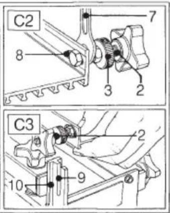
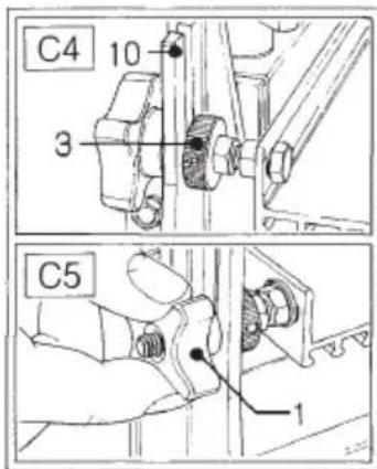
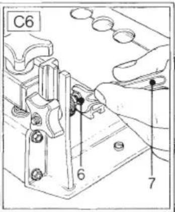
Adjusting the template bolts (fig. C1 - C6)
The template is held in place with two threaded bolts (2). If the bolts do not fit correctly into the lugs on the attachment, adjust as follows:
- Slacken the nuts (6) using a spanner (7).
- Place the template onto the attachment. Make sure that the adjustment bushes (3) are in front of the lugs (10) and the star knobs (1) behind the lugs. Insert the bolts correctly into the slots (9).
- Tighten the star knobs (1).
- Securely tighten the nuts (6).
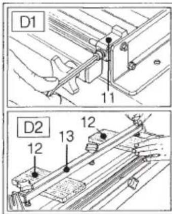
Adjusting the automatic centre locator for edge dowelling (fig. D1 - D29)
- If the workpieces are wider than 280 mm, remove the centre locking knobs.
- Slide the displacement stops (11) out of the way to each end of the dovetailing attachment.
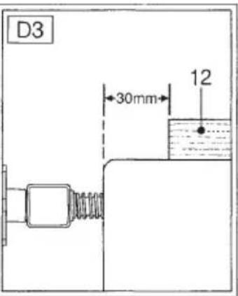
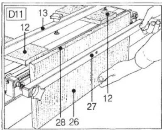
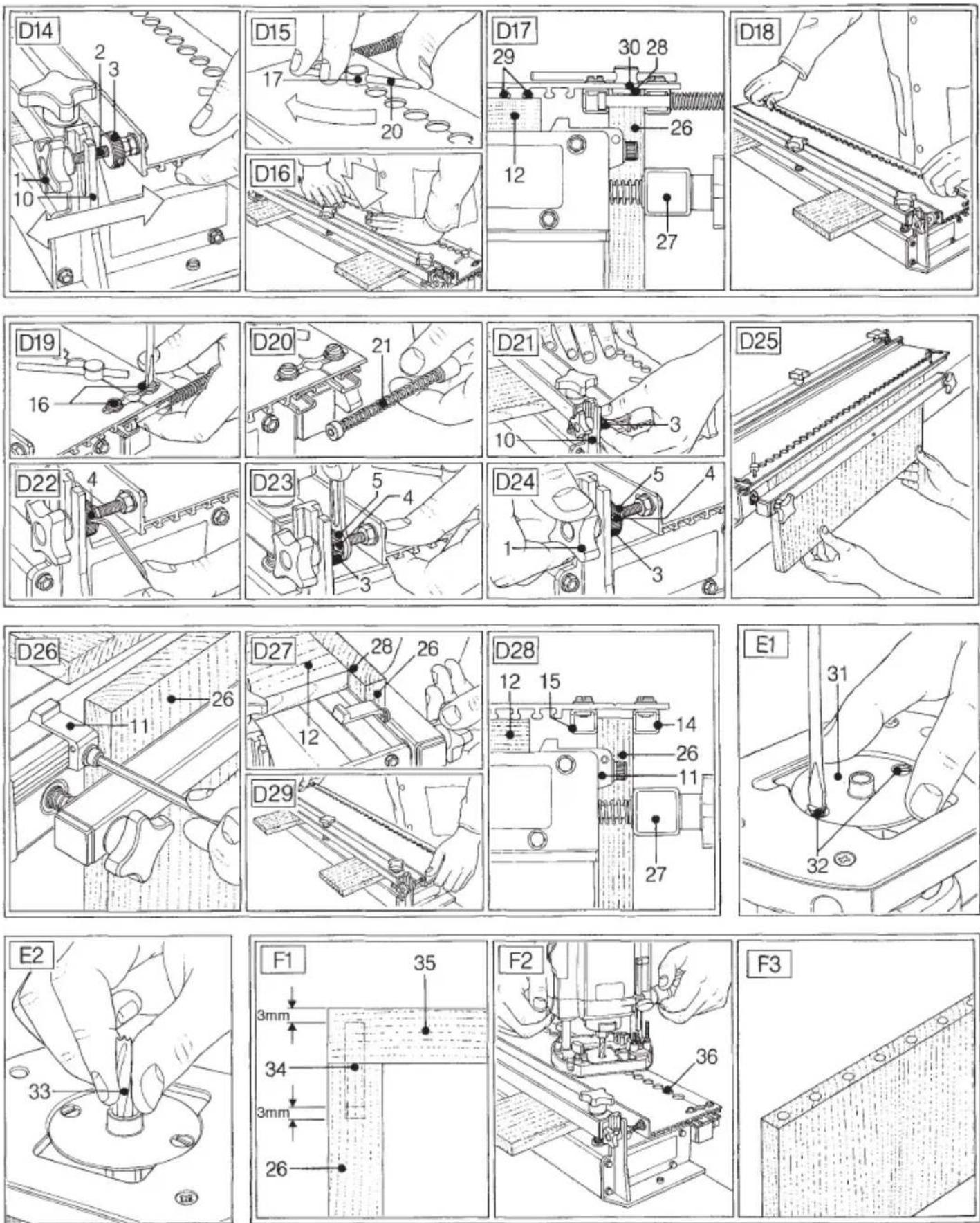
- Place two scrap pieces of wood (12) of the same thickness (>10 mm) under the ends of the top vice (13) to support the template. Position the front edge of the wood 30 mm behind the front edge of the dovetailing attachment (fig. D3) to allow the centering bar to move freely.
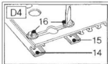
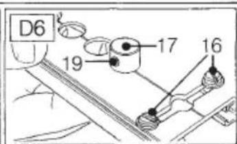
- Loosen the four screws (16).
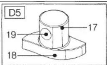
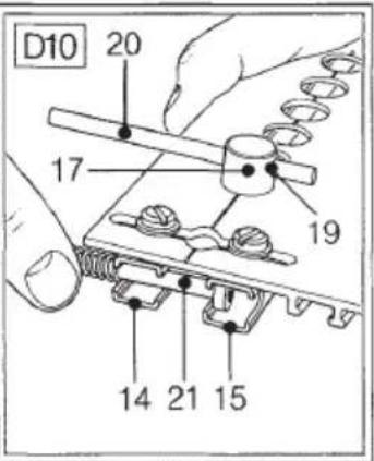
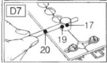
- Push the cylindrical part (17) of the plastic cams (18) through the end holes in the template from below. One of the small holes (19) should point to the front.
- Insert a tommy bar (20) into the hole (19) in each of the cams.
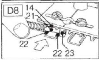
- Mount the two spring-loaded anchor assemblies (21) by sliding the rod into the centering bar (14) as shown (fig. D8).
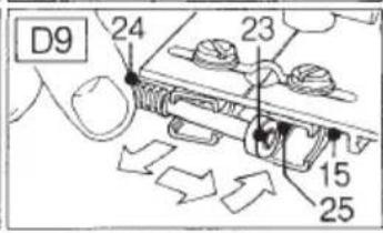
- Hold the rod (24) and push it towards the centre of the attachment to move the head (23) out. Push the rod (24) backwards to line up the head (23) with the rear centering bar (15) and rotate the rod to engage the head.
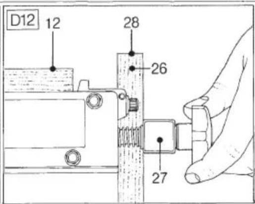
- Place the workpiece (26) vertically in the attachment and tighten the front vice (27).
- Place the top of the workpiece (28) approx. 10 mm above the top surface of the scrap wood (12). Do not fully tighten the front vice to allow the workpiece to be moved.
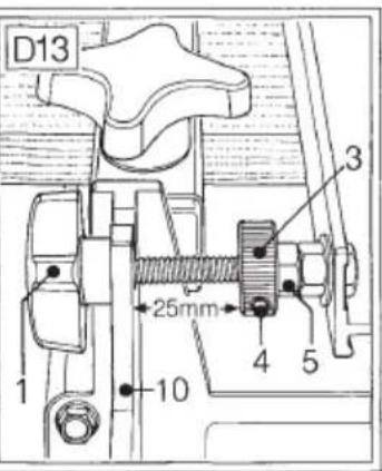
- Slacken the Allen screws (4) in the adjustment bushes (3) using a 2 mm Allen key.
- Slacken the locknut (5).
- Adjust the bushes (3) and star knobs (1) to set a distance of approx. 25 mm between the bushes (3) and the lugs (10).
- Place the template on the attachment. The threaded bolts (2) should move freely through the lugs (10) (fig. D14).
- Use the tommy bars (20) to rotate the cams (17) and open the centering bars (14) and (15). The template is positioned on the workpiece (26).
-
Release the tommy bars (20) to close the centering bars.
-
Push the template down until its feet are resting on the scrap wood and its front is resting on the workpiece (26) (fig. D16 & D17).
- Firmly tighten the front vice (27).
- Open the cams (17) and allow them to return slowly to their rest position. This will position the dowelling holes in the centre of the workpiece (fig. D18).
- Firmly tighten the four screws (16). The spring-loaded anchor assemblies (21) may now be removed.
- Hold the template down and rotate the adjustment bushes (3) against the lugs. Tighten the Allen screws (4) and the locknuts (5). Tighten the star knobs (1).
- Unclamp the workpiece and reposition it laterally to set the dowelling holes to the required position (fig. D25).
- Slide one of the displacement stops (11) against the side of the workpiece (fig. D26).
- Remove the template, the tommy bars (20) and the cams (18).
- Unclamp the scrap wood (12) and move it to the front against the workpiece. Unclamp the workpiece and align the top edge (28) with the top surface of the scrap wood (12) (fig. D27). Check with a set square.
- Firmly clamp the workpiece and move the scrap wood back to its former position (fig. D28).
- Replace the template and firmly clamp it in position with the star knobs.
Preparing the router (fig. E1 & E2)
- Fit the guide bush (31) to the router base using the screws (32) as shown.
- Mount the cutter (33) in the collet.
Adjusting the depth of cut (fig. F1 - F3)
The total depth of the mating bores in the two parts to be dowelled together should exceed the length of the dowel (34) by 3 mm.
- The depth of the bore in the horizontal workpiece (35) should be 3 mm less than the thickness of the wood.
-
The depth of the bore in the vertical workpiece (26) should be 3 mm more than the difference between the dowel length and the horizontal bore depth.
-
Place the router on the template with the nose of the guide bush in one of the holes (36). Plunge the router until the cutter is touching the vertical workpiece.
- Set the depth adjuster to the correct cutting depth.
- Allow the cutter to return to its rest position.
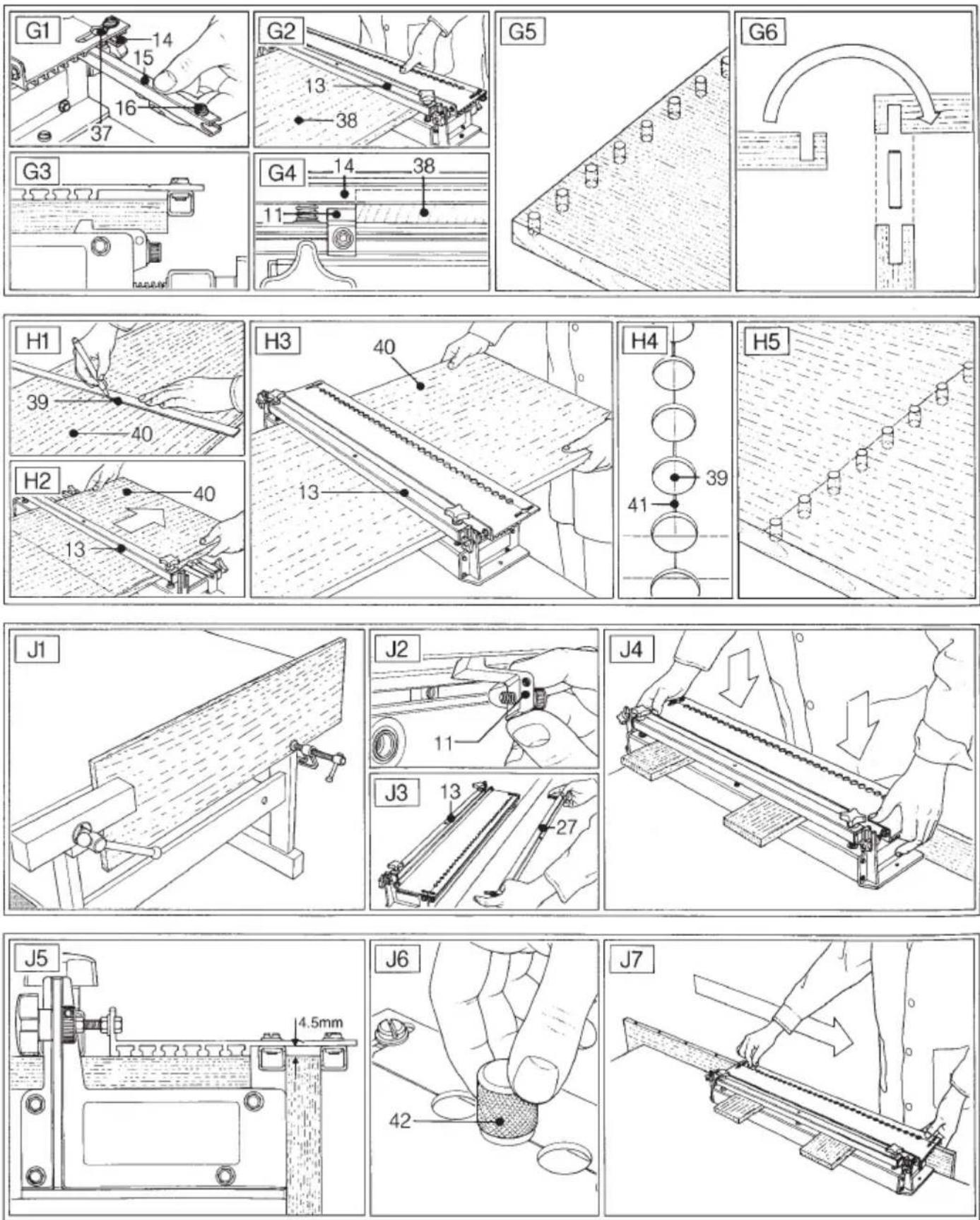
Locating the mating part for boring matching blind dowel holes (fig. G1 - G6)
- Slacken the two screws (16) holding the rear centering bar (15) by one turn. Remove the bar by moving it to the front and passing the screws through the holes (37).
- Remove the centre locking knob and place the workpiece (38) under the top vice (13). Place the template and tighten the star knobs.
- Slide the workpiece against the front vice (14) and displacement stop (11) and tighten the top vice (13).
- Set the correct cutting depth as described above.
Dowelling holes in the centre of the workpiece (fig. H1 - H5)
- Draw a line (39) on the workpiece (40) to mark the centre of the required holes.
- Remove the centering bars from the template.
- Slide the workpiece with the line (39) facing up onto the attachment and into the top vice (13). The line (39) should be approximately in line with the front of the attachment. Slide the workpiece against the displacement stop.
- Place the template and tighten the star knobs.
- Adjust the workpiece (40) to exactly align the line (39) with the marking (41) on the template.
- Tighten the top vice.
Edge dowelling on long workpieces (fig. J1 - J7)
- Centre and lock the template on a piece of wood of the same thickness as the workpiece.
- Remove the piece of wood, leaving the template locked in place.
• Take the attachment from the workbench. - Clamp the workpiece in vertical position against a workbench (fig. J1).
-
Remove the displacement stops (11) and the front vice (27) from the attachment.
-
Place the attachment over the workpiece, ensuring that the centering bars are located on each side of the workpiece (fig. J4). There should be a 4.5 mm gap between the top edge of the workpiece and the template (fig. J5).
- After boring the first hole, the appropriate locating pin should be inserted to stabilise the attachment.
- After boring all holes in the template, move the attachment along the workpiece until the first hole in the template is aligned with the last hole in the workpiece and continue working.
Instructions for use

• Always observe the safety instructions and applicable regulations.
- Also refer to your router manual.
Routing the dowelling holes (fig. F2)
- Make the adjustments as described above.
- Switch the router on.
- Plunge the cutter evenly into the workpiece to the required depth.

Do not plunge the cutter too slowly.
Consult your dealer for further information on the appropriate accessories.
Maintenance
Your DEWALT attachment has been designed to operate over a long period of time with a minimum of maintenance. Continuous satisfactory operation depends upon proper tool care and regular cleaning.

Lubrication
Your attachment requires no additional lubrication.

Unwanted products and the environment
Take your attachment to an authorized DEWALT repair agent where it will be disposed of in an environmentally safe way.
GUARANTEE
• 30 DAY NO RISK SATISFACTION GUARANTEE •
If you are not completely satisfied with the performance of your DEWALT tool, simply return it within 30 days, complete as purchased, to a participating Dealer, or an authorized DEWALT repair agent, for a full refund or exchange. Proof of purchase must be produced.
• ONE YEAR FREE SERVICE CONTRACT •
If you need maintenance or service for your DEWALT tool, in the 12 months following purchase, it will be undertaken free of charge at an authorized DEWALT repair agent. Proof of purchase must be produced. Includes labour and spare parts for the attachments. Excludes accessories.
• ONE YEAR FULL WARRANTY •
If your DEWALT product becomes defective due to faulty materials or workmanship within 12 months from the date of purchase, we guarantee to replace all defective parts free of charge or, at our discretion, replace the unit free of charge provided that:
• The product has not been misused.
• Repairs have not been attempted by unauthorized persons.
- Proof of purchase date is produced.
This guarantee is offered as an extra benefit and is additional to consumers statutory rights.
For the location of your nearest authorized DEWALT repair agent, please use the appropriate telephone number on the back of this manual.
PLANTILLA PARA ENSAMBLAJE CON CLAVIJAS DE6256
¡Enhorabuena!
Director Engineering and Product Development Horst Großmann
X. fopmann
1 Casquillo de guía 14 mm para DW620, DW621, DW625, DW626, Elu MOF177(E)
2 Tornillos M5
2 Tornillos M6
L'emballage contient:
Director Engineering and Product Development Horst Großmann
X. fopmann
DEWALT, Richard-Klinger-Straße 40, D-65510, Idstein, Tyskland
Sikkerhetsforskrifter
1 Føringshylse 14 mm til DW620, DW621, DW625, DW626, Elu MOF177(E)
2 M5 skruer
2 M6 skruer
1 Plasseringsstift 6 mm
1 Plasseringsstift 8 mm
1 Plasseringsstift 10 mm
2 Plastkammer
2 Spaker
2 Fjærbelastede festeanordninger
1 Instruksjonsbok
1 Splitt-tegning
Director Engineering and Product Development Horst Großmann
X. fopmann
DEWALT, Richard-Klinger-Straße 40, D-65510, Idstein, Alemanha
Director Engineering and Product Development Horst Großmann
X. fopman
Director Engineering and Product Development Horst Großmann
X. fopman
DEWALT, Richard-Klinger-Straße 40, D-65510, Idstein, Tyskland