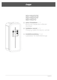
XEV1R22T2ER - Car charger HAGER - Free user manual and instructions
Find the device manual for free XEV1R22T2ER HAGER in PDF.


| Product Type | Electric vehicle charging station |
| Brand | Hager |
| Model | XEV1R22T2ER |
| Dimensions (H x W x D) | 549 x 251 x 173 mm |
| Net weight | 6 kg |
| Protection rating | IP55 / IK10 |
| Operating temperature | -25 °C to +50 °C |
| Supply voltage | 230 V~ (single-phase) / 400 V~ (three-phase) |
| Max current (Mode 3) | 32 A (single-phase: 7 kW, three-phase: 22 kW) |
| Max current (Mode 2) | 10 A (2300 W) |
| Connectors | T2/T2S socket (Mode 3) and TE/TF socket (Mode 2) |
| RFID reader | 13.56 MHz, compatible MIFARE, DESFire, NFC |
| Communication | WiFi 2.4 GHz, Ethernet RJ45, OCPP |
| Features | 6 mA DC detection, load shedding, input/output management, Smart Charging ISO15118 |
| Installation | Wall or pole mounting, by qualified electrician |
| Maintenance | Annual inspection of electrical connections |
| Safety | 40 A type C circuit breaker, type A differential switch, stuck contact detection, overcurrent protection |
| Standards | RED 2014/53/EU, NF-EN61851-1, EV Ready 1.4, ZE Ready 1.4 |
Frequently Asked Questions - XEV1R22T2ER HAGER
User questions about XEV1R22T2ER HAGER
0 question about this device. Answer the ones you know or ask your own.
Ask a new question about this device
Download the instructions for your Car charger in PDF format for free! Find your manual XEV1R22T2ER - HAGER and take your electronic device back in hand. On this page are published all the documents necessary for the use of your device. XEV1R22T2ER by HAGER.
USER MANUAL XEV1R22T2ER HAGER
XEV1R22T2TE XEV1R22T2TF XEV1R22T2
GB installation manual- p. 24 Charging station for electric vehicle
natural_image
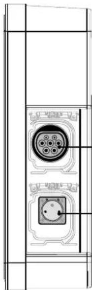
Technical line drawing of a dual electrical connector panel with two circular components (no text or symbols)Prise mode 3
Type T2S
Prise mode 2
Type TE
2. Installation
2.1. Ouverture

natural_image
Technical line drawing of a mechanical device with an open lid and internal compartments, showing a black arrow indicating rotation (no text or symbols present)
natural_image
Technical line drawing of a mechanical housing component with internal components and a magnified inset showing a gear mechanism (no text or symbols)
natural_image
Technical line drawing of a battery pack assembly showing internal compartments and housing (no text or symbols)2.2. Fixation

natural_image
Diagram showing a door panel with 'shager' label and a separate view of a wall-mounted device (no text or symbols on the main components)1
2
natural_image
Illustration of a hand using a tool to adjust a circular component with cross marks (no text or symbols)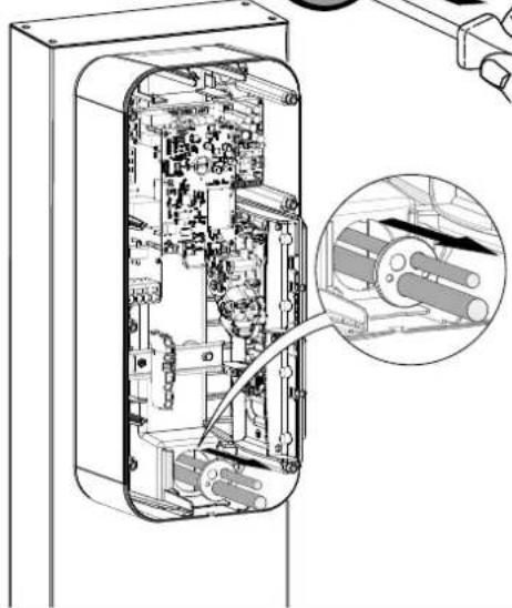
natural_image
Cross-sectional diagram of an electronic device showing internal components and a magnified inset of a cable assembly (no text or symbols)natural_image
Top-down schematic of an electronic device layout with components like a fan, circuit board, and battery (no text or labels)natural_image
Interior view of an electronic device casing with visible circuitry and wiring (no text or symbols)natural_image
Technical diagram of an electronic device showing internal components and a close-up view of the internal structure (no text or symbols present)natural_image
Cross-sectional diagram of an electronic device showing internal components and a close-up view of a device with arrows indicating motion (no text or symbols present)
OKNOK
natural_image
Technical line drawing of an electronic device showing internal components connected to a central cable (no text or symbols present)2
natural_image
Diagram of a mechanical component with a curved internal structure and a directional arrow indicating motion (no text or symbols)4
natural_image
Diagram of a door switch mechanism showing rotation and clockwise motion (no text or symbols)

9. Activation du HotSpot Wifi
natural_image
Circular diagram showing electronic components including a motor, battery, and circuit board (no text or labels)-
Description of the exterior 25
-
Installation 26
2.1. Opening 26
2.2. Mounting.... 26
-
Electrical connection 28
-
Electrical protections for charging stations.... 32
4.1. Installation and quality of the earthing according to the EV READY 1.4I label 32
4.2. Stuck contact detection, according to the ZE READY 1.4I and EV READY 1.4I labels 33
-
Fastening the cable support (optional) 34
-
Direct configuration....35
-
Finalisation 36
-
First use ....37
-
Activating the Wifi Hotspot....37
-
Charging station software configuration.... 38
10.1. Web server access.... 38
10.2. Identification page 38
10.3. Configurator 38
10.4. Configuration parameters 39
-
Description of the interior 40
-
Maintenance....42
12.1. Introduction 42
12.2. Normal operation.... 42
12.3. Anomaly indicators.... 42
12.4. Electrical maintenance 43
- Technical characteristics .... 44

Safety advice
- Electrical devices should only be installed and mounted by a qualified electrician. Accident prevention measures in force in the country must be respected. Failure to adhere to the installation instructions could lead to damage to the device, a fire or could be a danger to others.
- Please observe the measures and standards in force for Separated Extra Low Voltage (SELV) electrical circuits when installing and fitting the cables. Before any intervention on the device or the charge, switch off the charging station at the circuit breaker upstream and lockout the device if necessary. After opening the charging station, check that there is no voltage running to any of the parts.
- When installing the charging station, check that there are no environmental conditions (rain, mist, snow, dust, wind, etc.) that could pose a danger or cause a breakage during handling and when powering on again.
- Remember to take into account all of the circuit breakers delivering potentially dangerous voltages to the device or charge.
- Risk of electrical shock.
- Please separate the wiring into high and very low voltage currents (Ethernet).
- Remember to replace the cover after any operations.

How to dispose of this product (waste electrical and electronic equipment). (Applicable in European Union countries and other European countries with selective collection systems). This symbol on the product or its documentation indicates that it must not be disposed of at the end of its life with other household waste. As
uncontrolled disposal of waste can harm the environment or human health, please separate it from other types of waste and recycle it responsibly. You promote the sustainable reuse of material resources. Individuals are asked to contact the distributor who sold them the product or to check with their local authority to find out where and how they can dispose of this product so that it is recycled in an environmentally friendly manner. Companies are invited to contact their suppliers and consult the conditions of their sales contract. This product should not be disposed of with other commercial waste.
Hager hereby declares that the charging station products referenced XEV1Rxxx comply with the RED 2014/53/EU directive.
The CE declaration can be viewed at: www.hagergroup.net.
Non-contractual document, subject to modification without notice.
Recommendations
Any access to internal areas, beyond the areas described in this manual, is prohibited and voids the warranty and any other form of support. It can be damaging to the parts and/or to the electronic components. These products have been defined so that they do not have to be accessed during product implementation and maintenance operations.
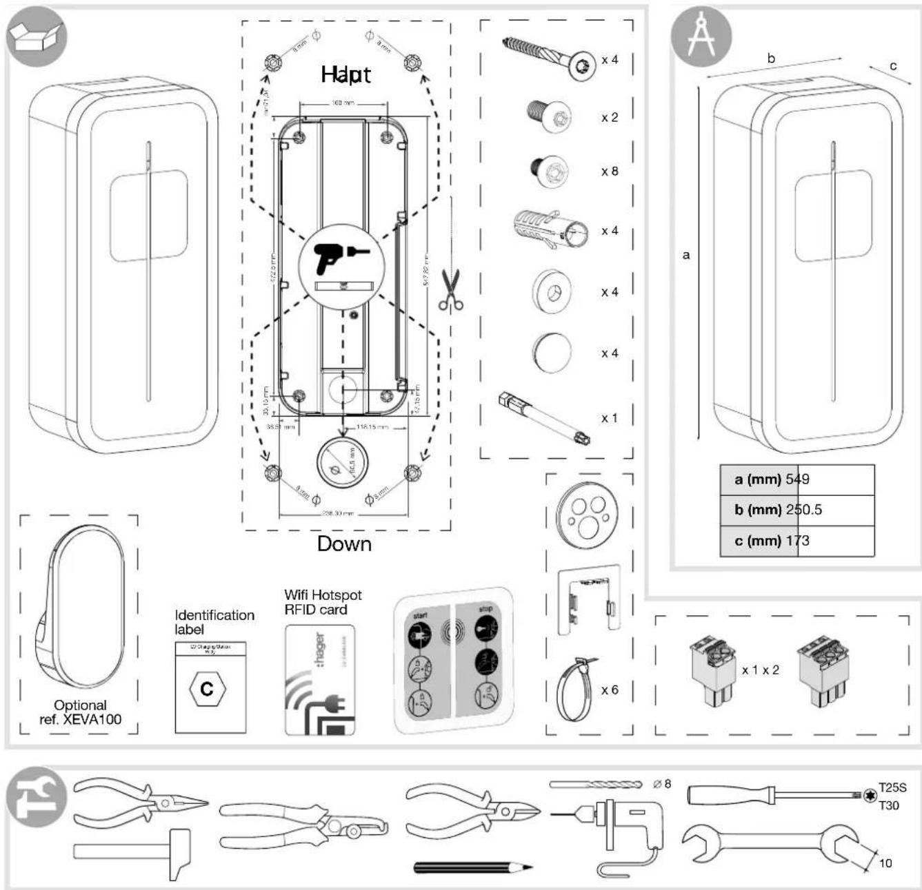
| a (mm) 549 |
| b (mm) 250.5 |
| c (mm) 173 |
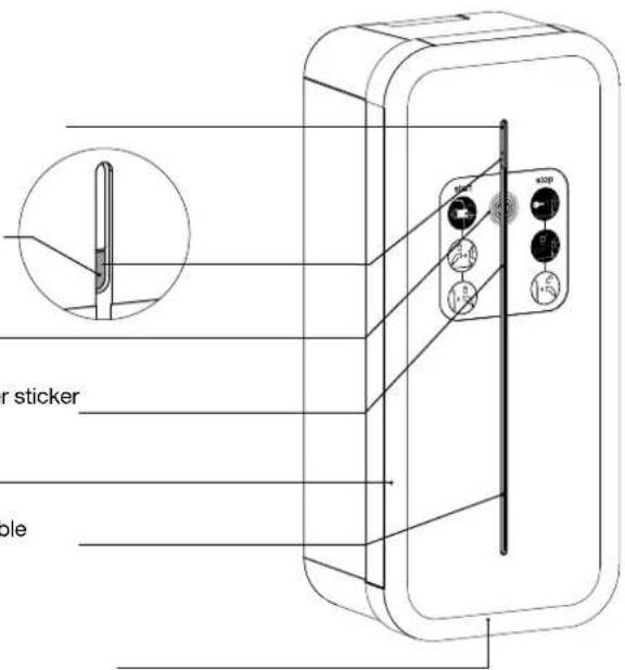
- Description of the exterior
- Exterior
Lighting strip
Hover button
RFID zone
Location of user sticker
Frame
Location for cable support
Cover opening
natural_image
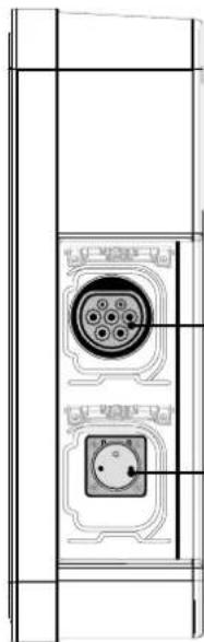
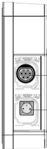
Technical line drawing of a dual electrical connector panel with two circular components (no text or symbols)Mode 3 socket
T2S
Mode 2 socket TE or TF type (depending on version)
2. Installation
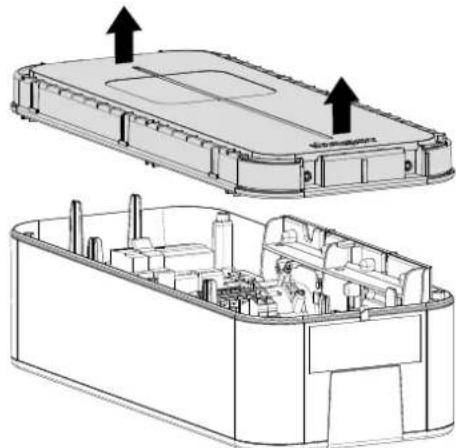
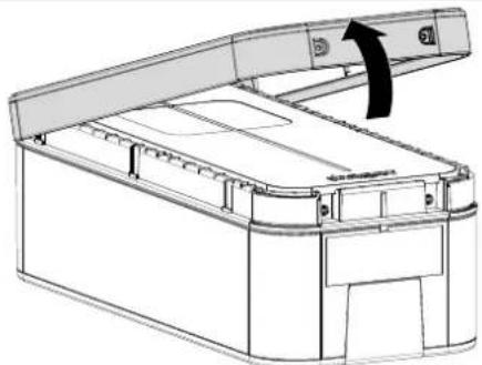
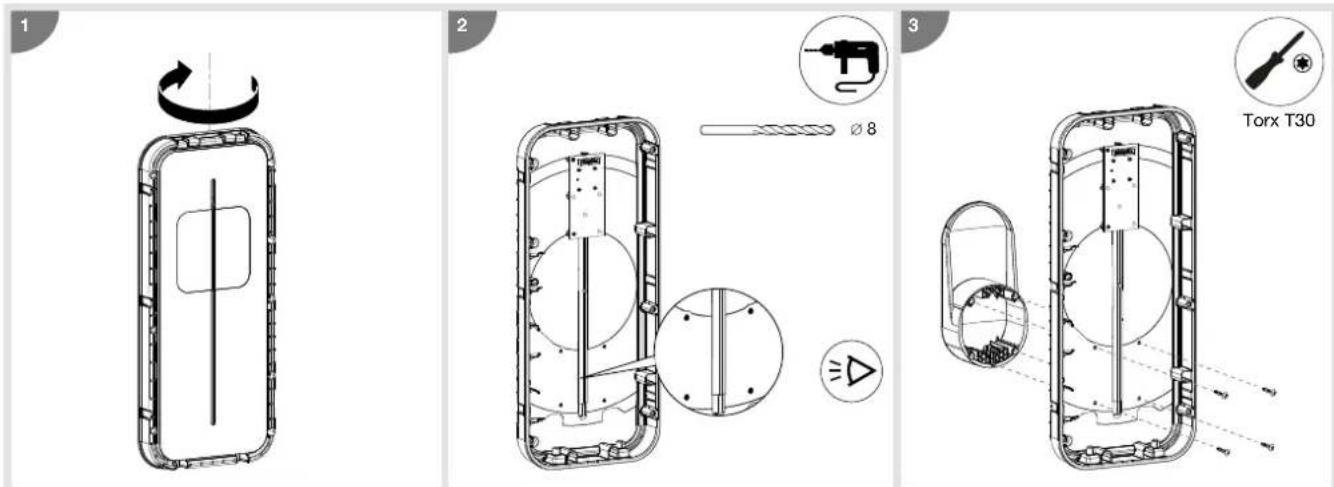
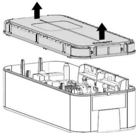
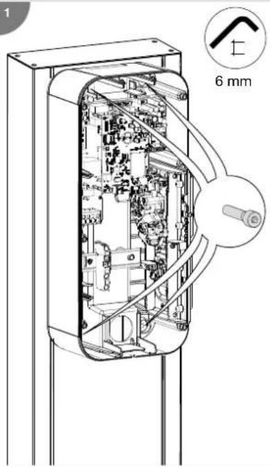
2.1. Opening

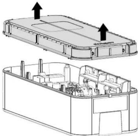
The charging station must be switched off before opening.
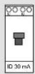
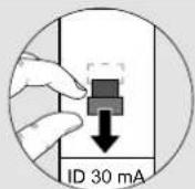

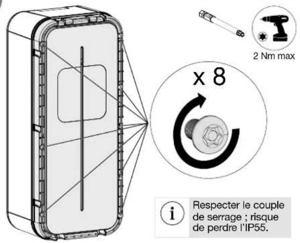
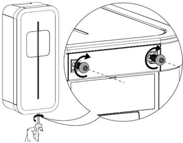
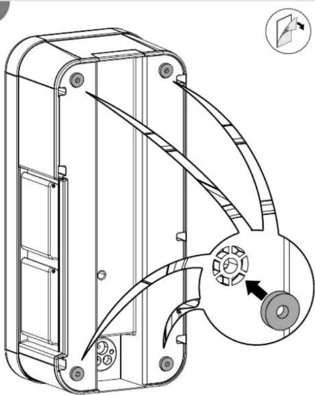
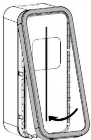
When leaving the factory, the frame and the front panel are not screwed on, and the cable of the interface board is not connected.
1
natural_image
Line drawing of a mechanical device with an open lid and arrow indicating rotation (no text or symbols)3
natural_image
Technical line drawing of a mechanical housing component with internal components and a close-up inset showing a gear mechanism (no text or symbols)2
natural_image
Technical line drawing of a battery pack assembly showing internal components and mounting points (no text or symbols)2.2. Mounting

Before mounting the charging station, please ensure that all of the cables are present:
- 3 Ph + N + Earth for a three-phase charging station, cable diameter: 5G10 or 5G16 flexible or rigid or 1Ph + N + Earth for a single-phase charging station, cable diameter: 3G10 or 3G16 flexible or rigid.
- an RJ45 cable for control card communication.
- a 2-wire cable for the shunt coil return of the power electronic board (ZE Ready option).
- the minimum cable diameter for a charging station with a current rated at 32 A is 10mm^2 .
- the maximum cable diameter is 16 ~mm^2 for a multi-strand cable and 10 ~mm^2 for a single-strand cable.

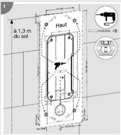
- The mounting system must be suitable for the support on which the product is installed.
- The fastenings provided are suitable for concrete and solid masonry.


natural_image
Simple line drawing of a brick wall and a door with a plus sign, no text or symbols present1
2
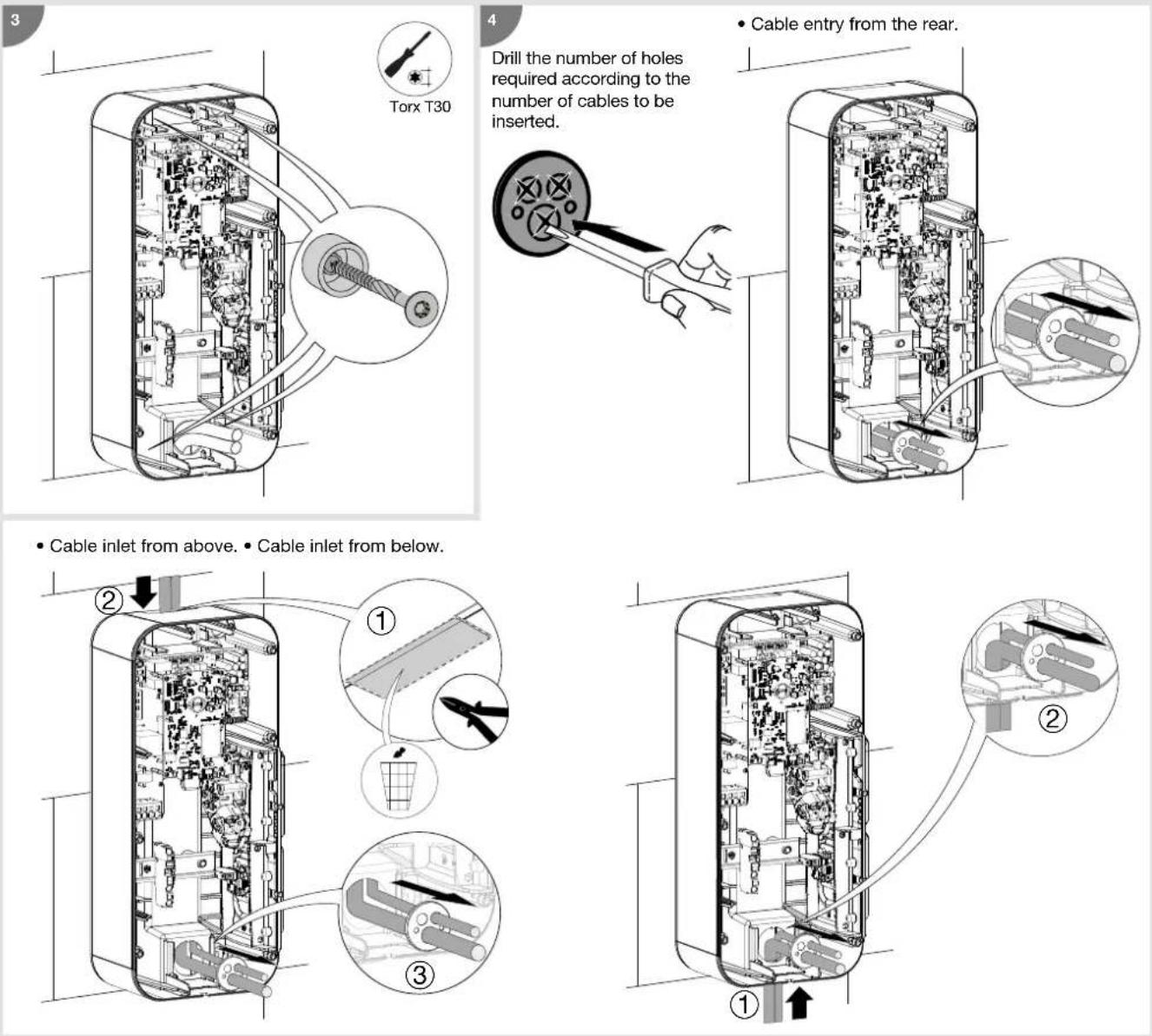
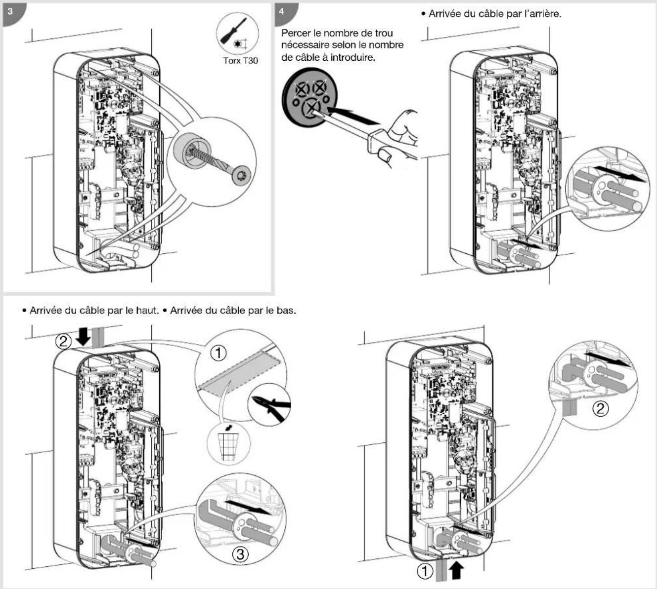
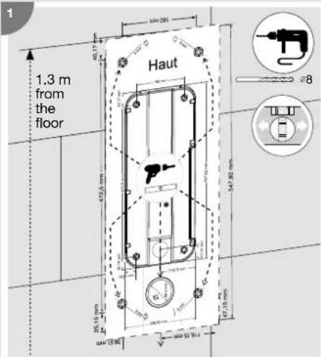
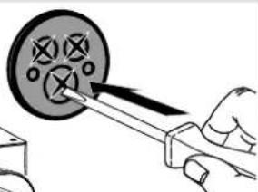
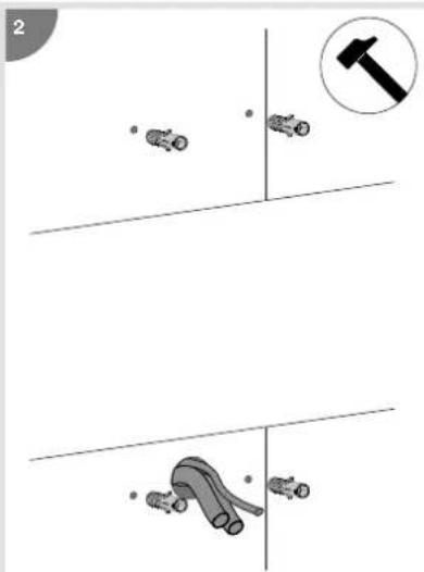
Drill the number of holes required according to the number of cables to be inserted.

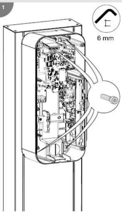
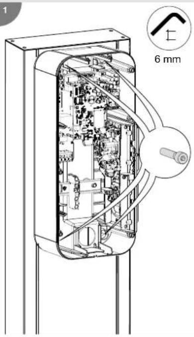
Refer to the instructions supplied with the stand to install the XEVA110 (for 1 charging station) or XEVA115 (for 2 charging stations) base and stand. Then follow the steps below.

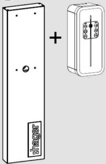
natural_image
Diagram showing a shager cabinet with a plus sign and its internal circuit switch (no text or symbols present)1
2
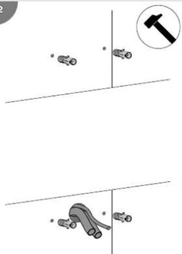
2 Drill the number of holes required according to the number of cables to be inserted.
natural_image
Illustration of a hand using a tool to adjust or install a circular component with cross marks (no text or symbols present)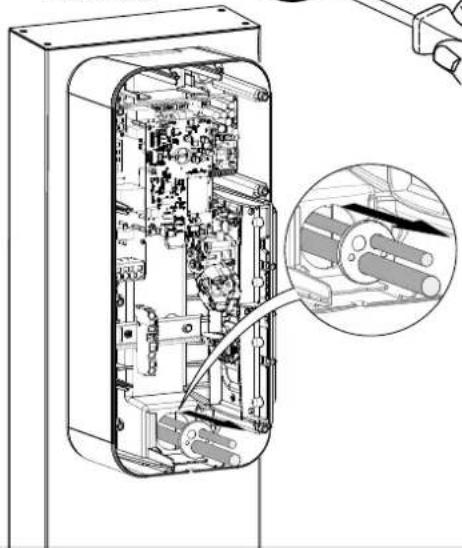
natural_image
Technical line drawing of an internal electronic device with a magnified inset showing internal components (no text or symbols)3. Electrical connection
1
Charging station power cabling
- 3 Ph + N + Earth wiring
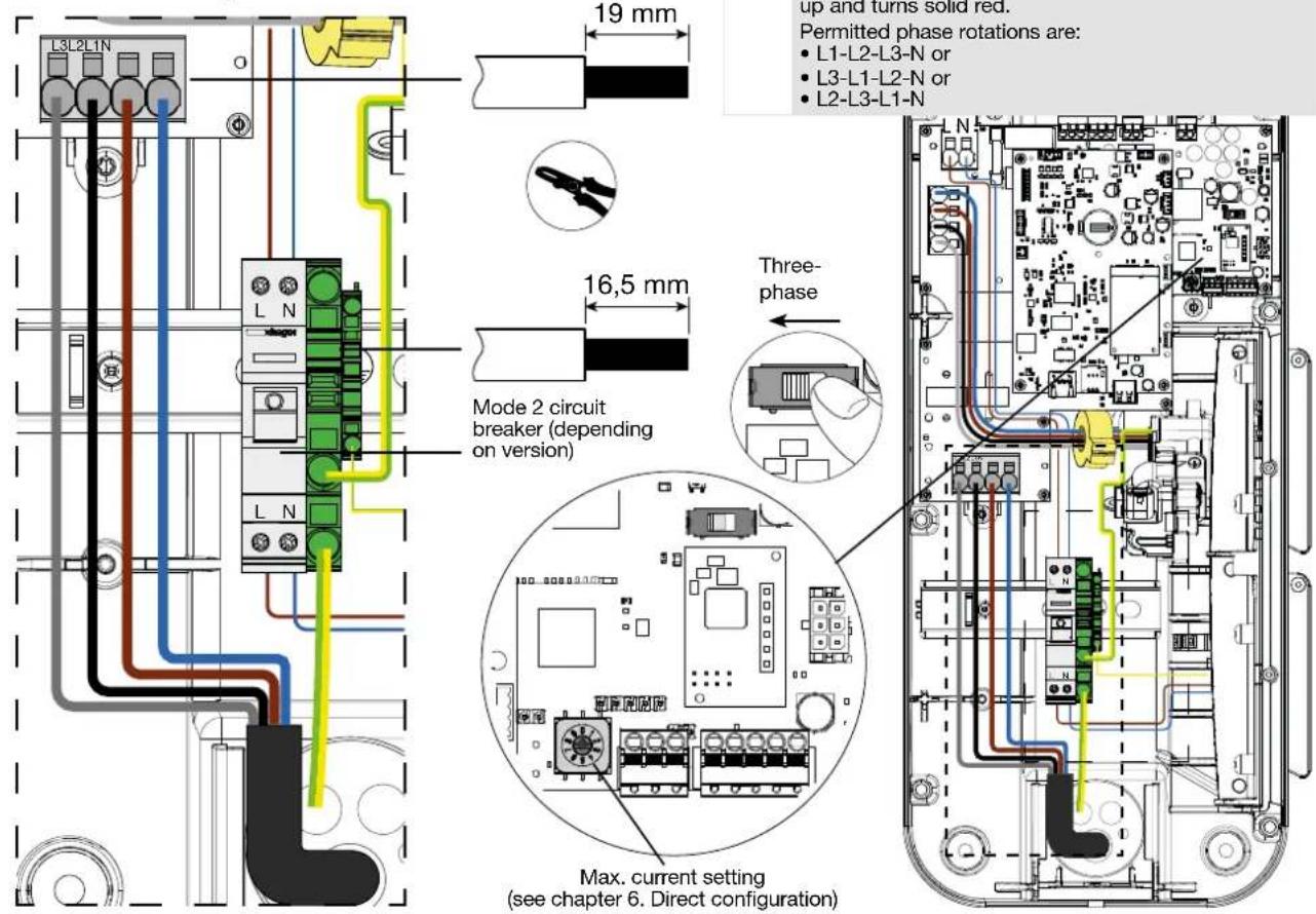
• 1 Ph + N + Earth wiring
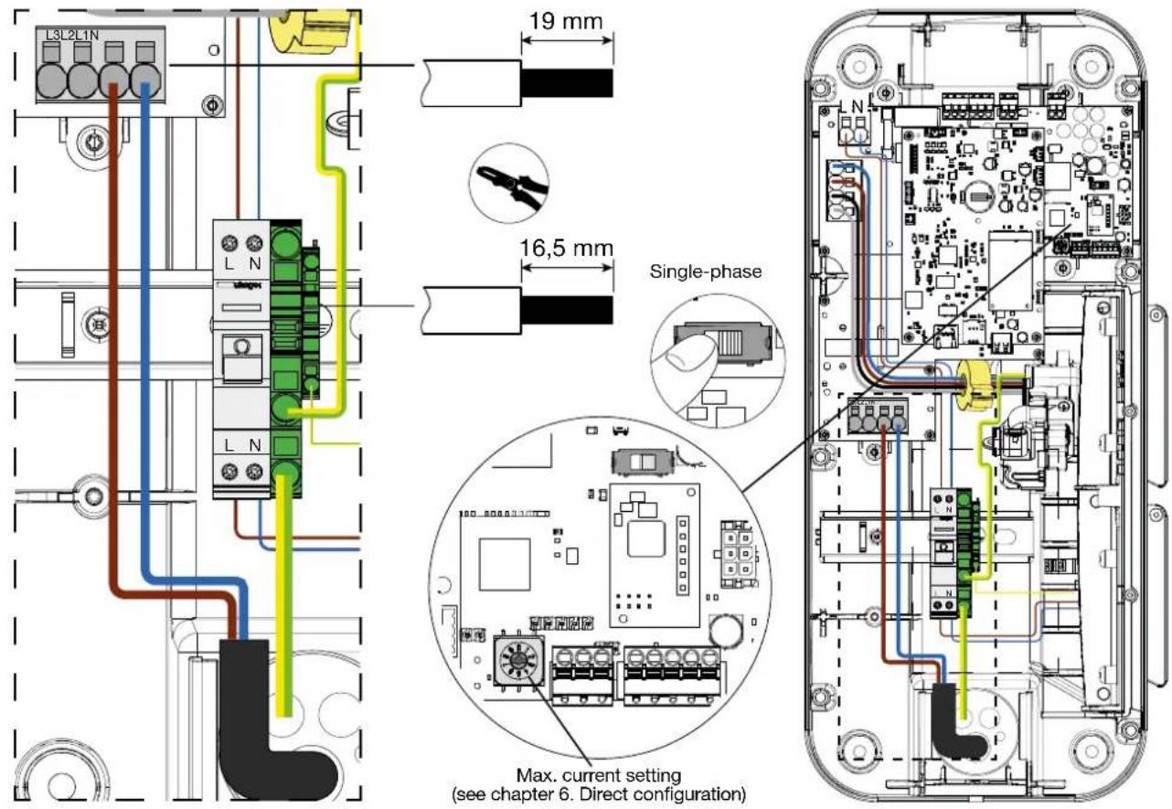

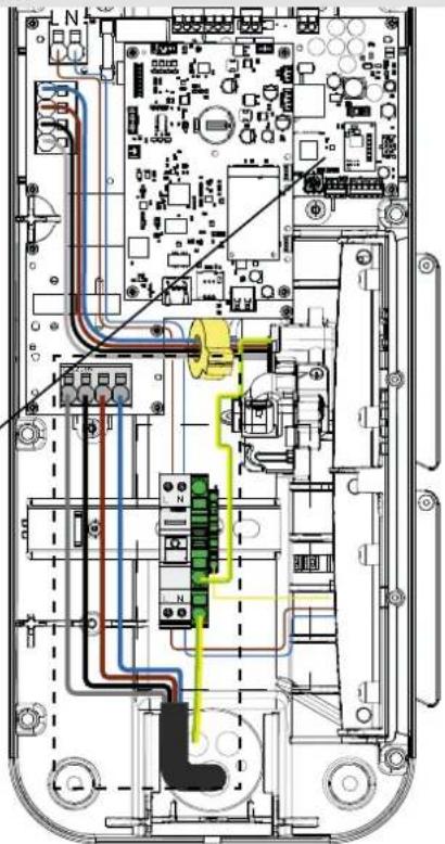
Pay close attention to the phase sequence when connecting to the terminal block (marked L3-L2-L1-N). This protection ensures consumption data is correctly measured and calculated. A critical error occurs if the phase sequence is incorrect, and the status LED lights up and turns solid red.
Permitted phase rotations are:
• L1-L2-L3-N or
• 13-1 1-1 2-N or
• L2-L3-L1-N
natural_image
Interior view of an electronic device showing circuit board, connectors, and wiring (no text or symbols visible)2
RJ45 Cat 6 Ethernet cable wiring
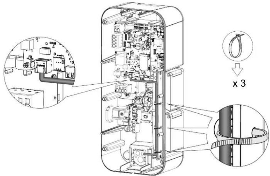
3
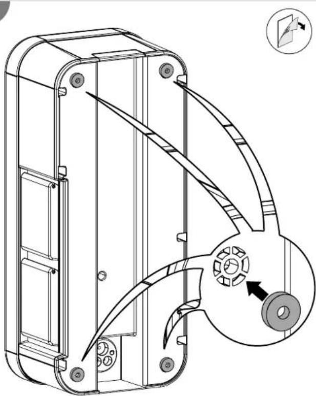
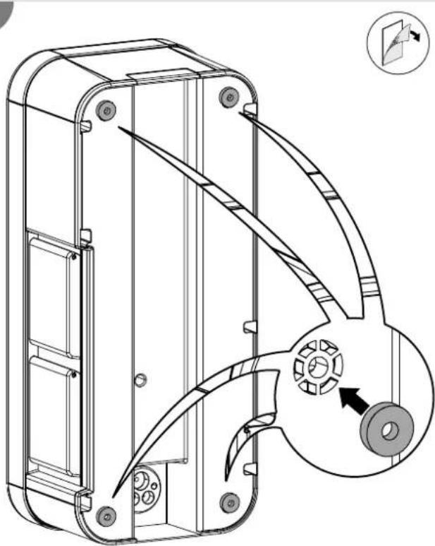
Position the perforated membrane
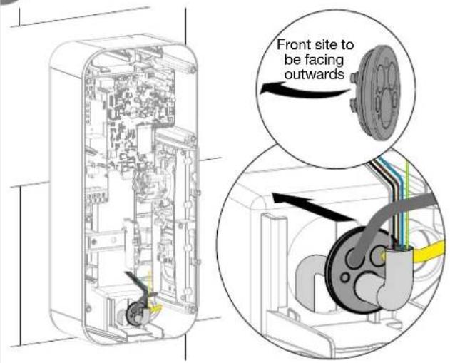
4
Position the cable gland
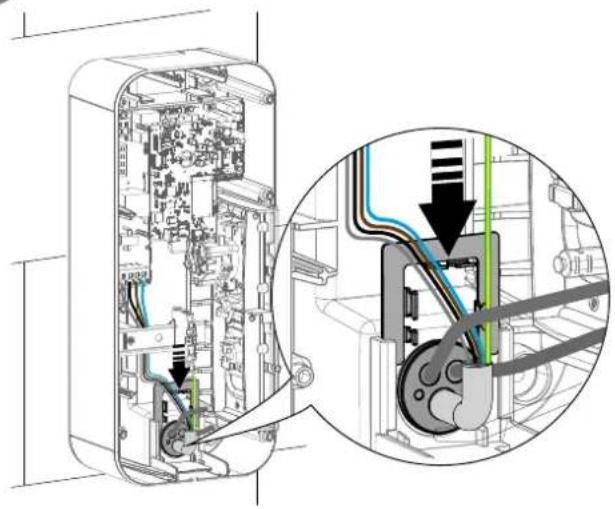
natural_image
Technical diagram of an electronic device showing internal components and a close-up view of the internal structure (no text or symbols present)5
Use the cable ties
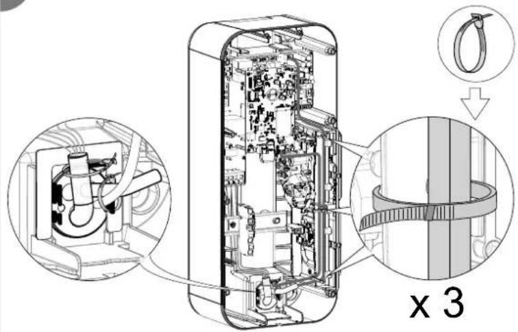
6
Position the screw covers

natural_image
Cross-sectional diagram of an electronic device showing internal components and a close-up view of a device with arrows indicating motion (no text or symbols present)
Wiring for the stuck contact detection function for ZE Ready
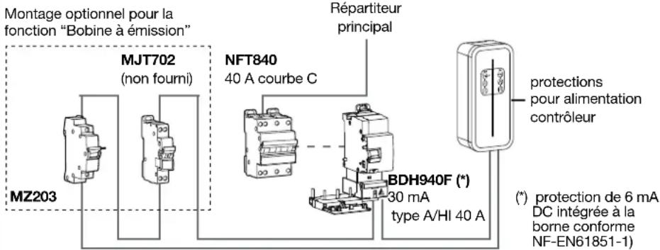
The shunt coil trigger - 230/415 VAC - HAGER MZ203 is an additional, non-compulsory safety mechanism that complements the mandatory differential switch + circuit breaker pairing, in order to ensure the complete electrical protection of your charging station.
It is implemented to cut the power supply to the charging station in the event that the contactor of the T2/T2S socket becomes stuck. The shunt coil must be present in order to obtain ZE Ready certification.
It couples to the circuit breaker, enabling it to be tripped remotely.
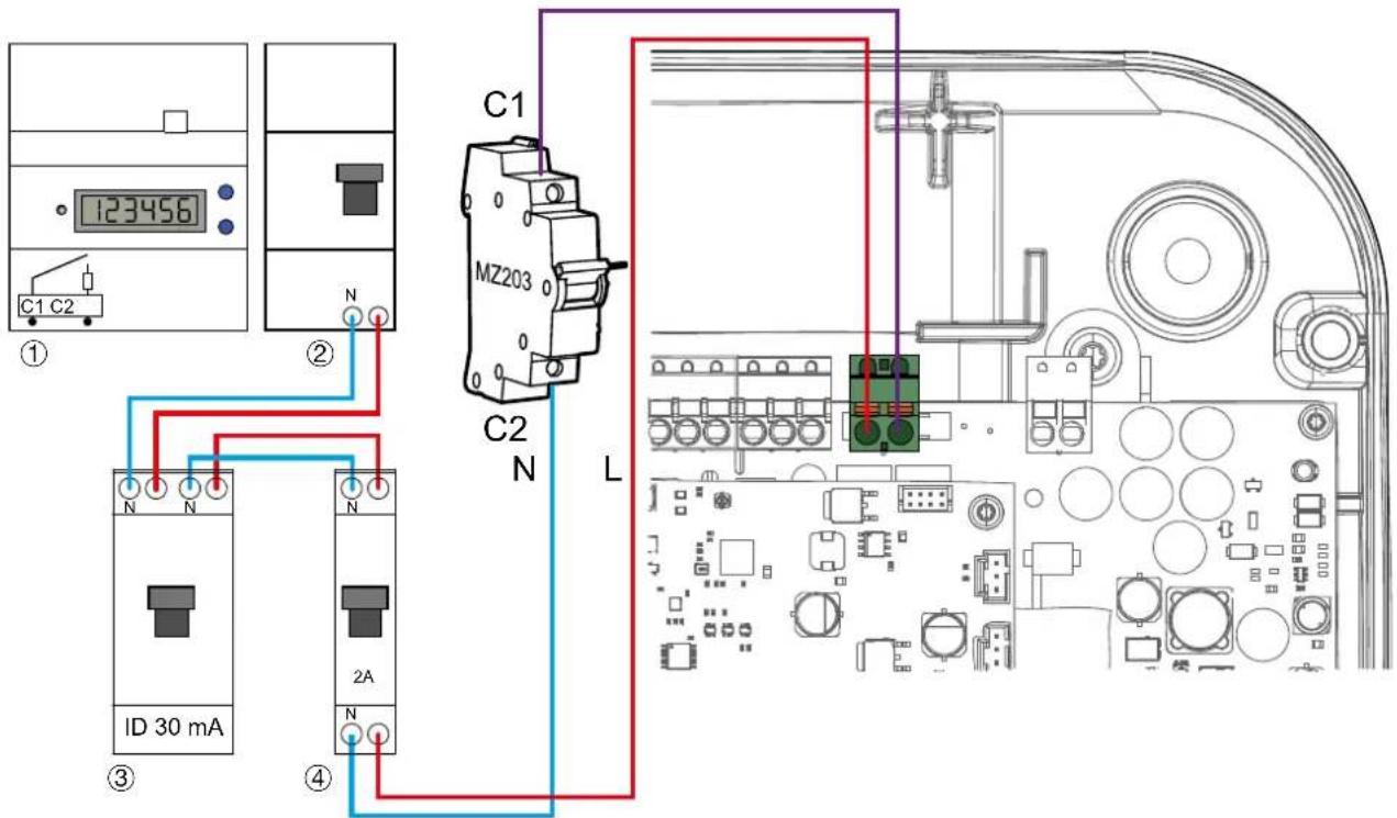
① Supplier electronic meter
② Subscriber circuit breaker/supplier entry point
③ 30 mA differential switch
④ 2A protection circuit breaker
8
Wiring for the Input/Output functions

Inputs/outputs can be managed from the local configurator. The factory settings are below:
- input IN1: if the 230 V is available unauthorised load / 0 A load shedding,
- input IN2: if the 230 V is available -50% load reduction,
- output OUT1: if charging is in progress - the relay is closed.
- Input 1/Input 2
Use scenario:
- 50% load reduction for load shedding function,
- vehicle charges during off-peak hours (according to tariff subscription),
- charge optimisation related to the start-up of an energy production source (photovoltaic, cogeneration).
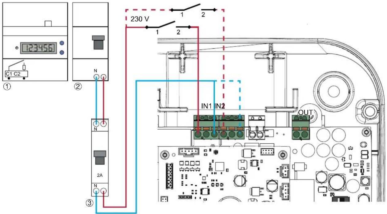
- Output 1
Use scenario:
- 50% load reduction information output,
- output triggering an indicator light or ambient lighting to indicate charging in progress,
- information that charging is in progress via an energy production source (example: cogeneration/Combined Heat & Power).
Output:
- 0 V to 30 V = / 10 mA to 500 mA
- 0 V to 250 V ∠10 mA to 500 mA
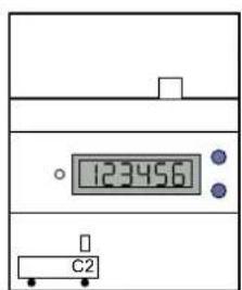
①
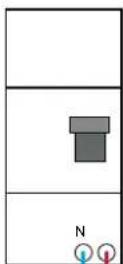
②
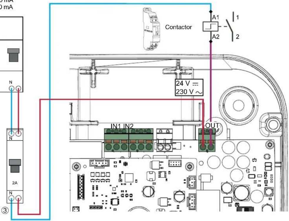
① Supplier electronic meter
② Subscriber circuit breaker/supplier entry point
③ 2 A protection circuit breaker
4. Electrical protections for charging stations
4.1. Installation and quality of the earthing according to the EV READY 1.4I label
- Single-phase
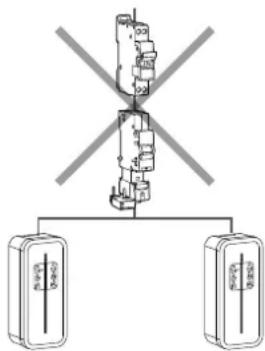
flowchart
graph TD
    A["Central Hub"] --> B["Client 1"]
    A --> C["Client 2"]
OKNOK
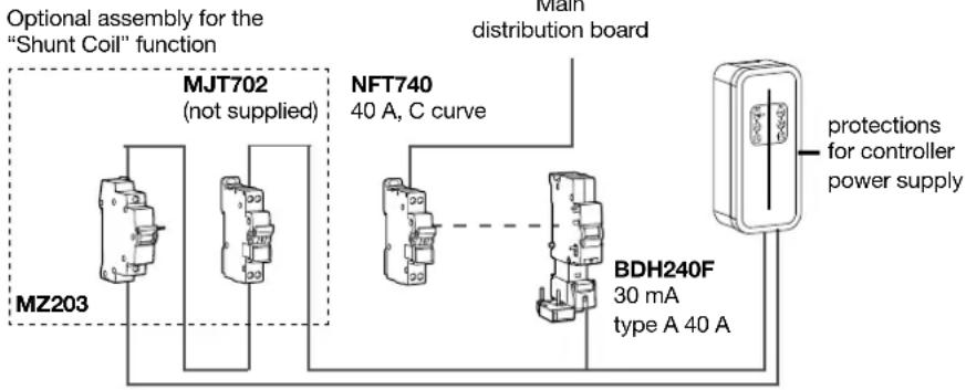
flowchart
graph TD
    A["MZ203"] --> B["MJT702 (not supplied)"]
    B --> C["NFT740 40 A, C curve"]
    C --> D["BDH240F 30 mA type A 40 A"]
    D --> E["Main distribution board"]
    E --> F["protections for controller power supply"]

The references in this diagram are for information purposes only and only valid for the French market. For countries other than France, refer to the charging station's electrical protection features (chapter 11. Technical characteristics) for the selection of protections to install.
- Three-phase
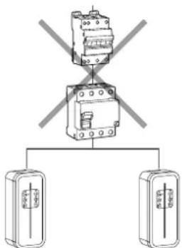
OKNOK
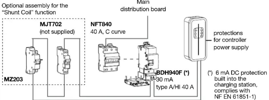

The references in this diagram are for information purposes only and only valid for the French market. For countries other than France, refer to the charging station's electrical protection features (chapter 11. Technical characteristics) for the selection of protections to install.
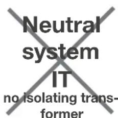
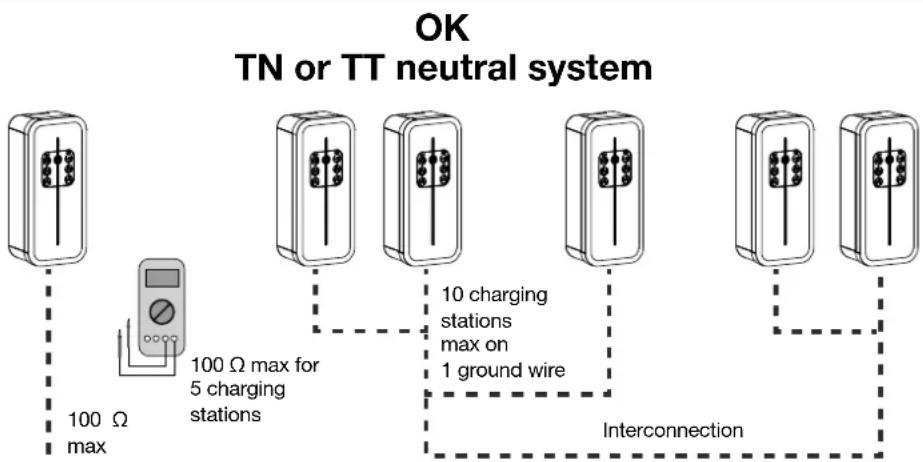
• Quality of the earthing according to the EV READY label 1.4
NOK
flowchart
graph TD
    A["100 Ω max"] --> B["100 Ω max for 5 charging stations"]
    B --> C["10 charging stations max on 1 ground wire"]
    C --> D["Interconnection"]
    style A fill:#f9f,stroke:#333
    style B fill:#ccf,stroke:#333
    style C fill:#cfc,stroke:#333
    style D fill:#fcc,stroke:#333

According to NF EN 61851-1, this charging station contains an RDC-MD compliant with IEC 62955. If a DC component > 6 mA is detected in the fault current, this RDC-MD acts on the power relays built into the charging station, automatically cutting the power supply to the charge point. This 6 mA DC detecting device eliminates the need for type B differential protection.
All of the circuits must be fully installed in the same building structure (from an electrical point of view).
4.2. Stuck contact detection, according to the ZE READY 1.4I and EV READY 1.4I labels
All of the charging stations have a detection mechanism for detecting contacts that are stuck.
According to the EV Ready 1.4I standard, the charging station must be protected by a circuit breaker with a shunt coil triggering device.
| Selector | Recommended circuit breaker rating | Operating current | EV Ready 1.4 ZEReady 1.4 | |||
| Sin-gle-phaseCharging station | Three-phaseCharging station | Sin-gle-phaseCharging station | Three-phaseCharging station | |||
| 0 40 A | 32 A OK OK | OK OK | ||||
| 1 32 A | 25 A OK OK | OK OK | ||||
| 2 25 A | 20 A OK OK | OK OK | ||||
| 3 | NOK NOK NOK NOK NOK NOK NOK NOK NOK NOK NOK NOK NOK NOK NOK NOK NOK NOK NOK NOK NOK NOK NOK NOK NOK NOK NOK NOK NOK NOK NOK NOK NOK NOK NOK NOK NOK NOK NOK NOK NOK NOK NOK NOK NOK NOK NOK NOK NOK NOK NOK | 16 A OK OK NOK OK | ||||
| 4 13 A | ||||||
| 5 10 A | ||||||
| 6 6 A | ||||||
| 7 N/A | --- | |||||
| 8 N/A | --- | |||||
| 9 Return to facto-ry setting | ---- | |||||

All of the circuits must be fully installed in the same building structure (from an electrical point of view).
5. Fastening the cable support (optional)

The cable support can be fastened to the wall or to the front panel of the charging station.
- Wall mounting
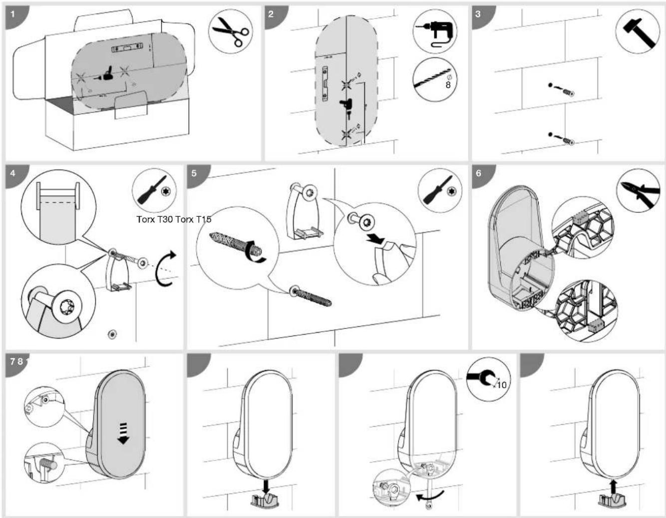
- Mounting on the front panel of the charging station
6. Direct configuration
The charging station can be configured directly on the electronic board to adjust the phase number and maximum current.
Should there be conflicting information between a software configuration and the physical setting, the lowest value is applied.
The maximum operating current can be selected using the selector.
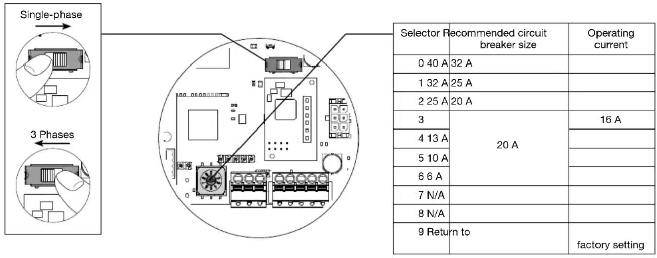
Return to factory setting procedure:
- Switch off the charging station for 2 minutes.
- Set the selector to position "9".
- Close the cover again and switch on the charging station.
- The charging station flashes yellow rapidly during start-up.
- The charging station flashes red; return to factory setting is complete.
- The charging station must have a steady red light (the selector is in position 9 Return to factory setting).
- Switch off the charging station for 3 minutes.
- Set the selector to a position between 0 and 6.
- Close the cover and switch on the charging station again.
7. Finalisation
1
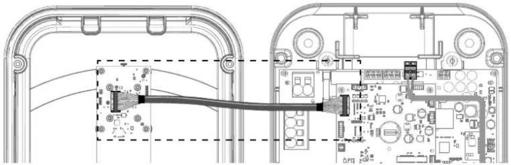
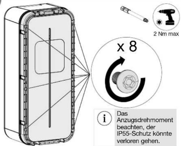
Wire the ribbon cable of the interface board.

Remember to reinforce the circuit breaker of the Mode 2 socket (depending on version).
natural_image
Technical line drawing of an electronic device showing internal components connected to a cable (no text or symbols present)2
3
natural_image
Diagram of a mechanical component with a curved internal structure and directional arrow (no text or symbols)4
natural_image
Diagram of a door switch mechanism showing rotation and clockwise motion (no text or symbols)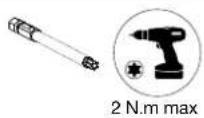
5
1. Remove the back of the sticker.
- Adjust the sticker in the intended area.
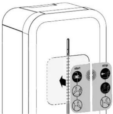
- Remove the protective film from the front of the sticker.


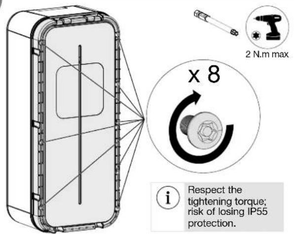
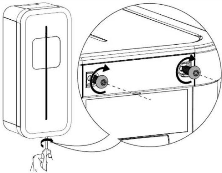
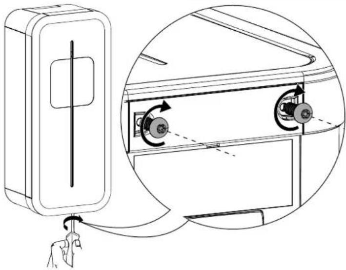
The charging station must only be switched on after the front panel has been locked.
8. First use: Wifi Hotspot
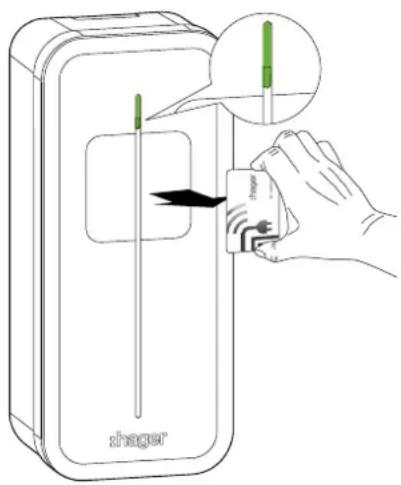
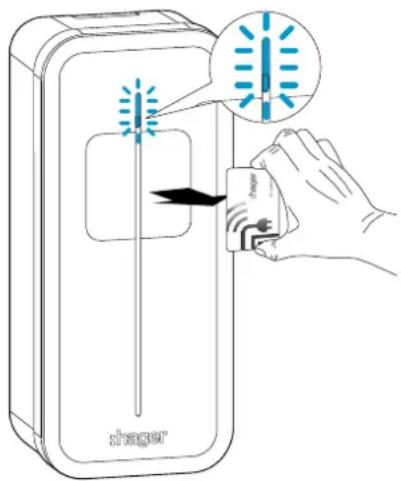
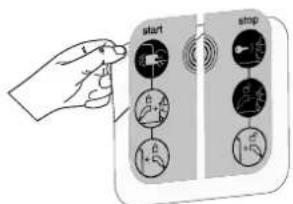
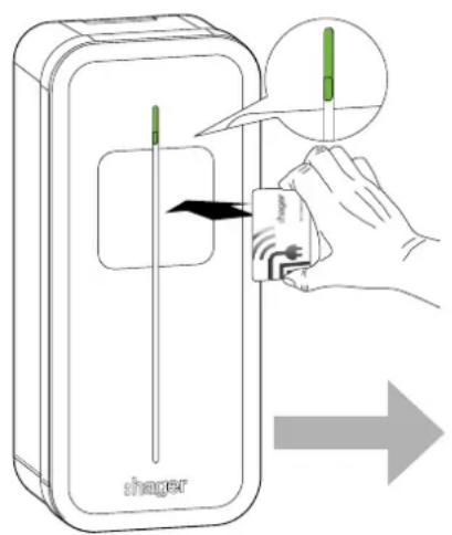
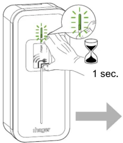
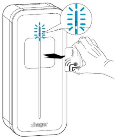
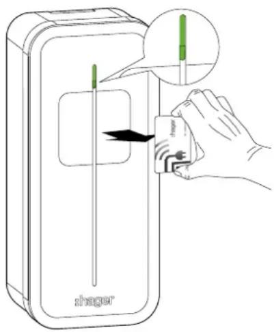
After starting up (flashing yellow) the charging station to use it for the first time, it will wait for a "Wifi Hotspot" RFID card and flash orange. You can use this card to activate the Wifi Hotspot to access the charging station's configuration.
If 5 minutes go by without an RFID card being used, a dummy card is saved and activating the Hotspot will not be possible. You can cancel this step by placing your hand on the front panel for 10 seconds.
You can change the "Wifi Hotspot" RFID card at a later time using the configuration software via the Hotspot or Ethernet.
A factory reset will also erase the "Wifi Hotspot".
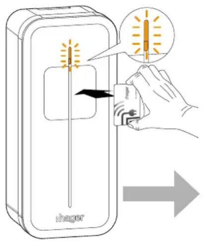
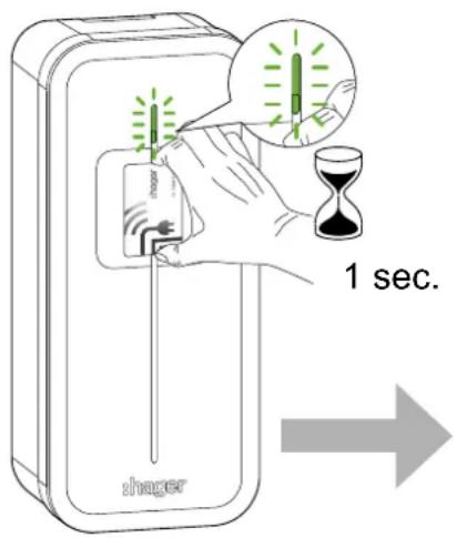
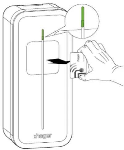
9. Activating the Wifi Hotspot
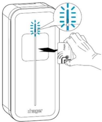
Once you have saved a "Wifi Hotspot" RFID card and allowed the RFID reader to scan it, the charging station switches to "Wifi Hotspot" mode. The charging station will broadcast its own Wifi, using the default username "hager-evcs-[last6charUID]" and the password "hager[last6charUID]".
Example:username → hager-evcs-ab4df5 password → hagerab4df5

Usernames and passwords are case sensitive.

If you lose your Wifi Hotspot card, you will have to use an Ethernet cable or factory reset the charging station in order to access the configuration software.
10. Charging station software configuration
Initial precautions
Before using the configuration software, please refer to the charging station installation manual.
Device to be installed and configured only by an electrical installer according to the installation standards applicable in the country.
Introduction
The charging station is equipped with an embedded web server to configure it.
By default, the charging station is configured as a "DHCP client" and, as a result, requires a router with a "DHCP Server" function to operate within the LAN.
If the charging station does not detect the DHCP server, it automatically assigns a fixed IP address (by default: 192.168.0.100), which can be set in the software configuration.
10.1. Web server access
There are several ways to access the charging station configurator.
The configurator is compatible with different screen sizes, such as a laptop, tablet or smartphone.
10.1.1. Via the charging station name (HostName)
The web server can be accessed directly by entering the address of the charging station name (Host name) in the web browser.
The exact address is specific to each charging station, indicating the last 6 characters of its UID code specified on the product label or on the side configuration label.
Address format: https://hager-evcs-[6derniers_caractères_UID]/ (example: https://hager-evcs-ab4df5/).
10.1.2. Via its IP address
The web server can be accessed by entering the charging station's IP address in the web browser.
The charging station's IP address can be detected using an "IP Scanner" third-party application from the same LAN, or if the charging station does not detect the DHCP server using its fallback IP address (default: https://192.168.0.100/).
In Hotspot mode, the charging station's IP address is https://10.0.0.1/.
10.2. Identification page
The configurator is protected by a user name and password.
By default, these credentials are:
User name: admin
Password: 1234
When connecting for the first time, you will be asked to change the password to a "strong" password. A "strong" password follows these rules:
-
has more than 8 characters,
-
includes at least 1 character in lower case letters,
-
includes at least 1 character in upper case letters,
-
includes at least 1 special character,
-
includes at least 1 number.
You can change the password in the configurator.
If you lose these credentials or make more than 10 consecutive incorrect attempts, a factory reset must be performed in order to return to the default settings. Warning: a factory reset erases all of the parameters.
10.3. Configurator
You will find an interface with 4 pages in which the parameters can be modified:
- Configuration: enables the configuration of the charging station's main settings,
- Live Debug: provides the status of the charging station for maintenance operations,
- Logs: enables recovery of information on errors and charging sessions,
- Settings: enables configuration of the configurator credentials and return to factory settings.
10.4. Configuration parameters
The "Save" button saves and applies the parameters.
The "Cancel" button cancels all unsaved changes.
The "Restart" button restarts the charging station.

Certain parameters require the charging station or services to be restarted for them to be applied.
10.4.1. OCPP
Enables configuration of the connection to an OCPP server.
- OCPP server: OCPP server address
- Authentication: authentication method for the OCPP server
- Login: OCPP user name
- Password: OCPP password
- ChargePoint ID: charging station user name
- RFID Access: activation of the RFID management by the OCPP server
- Charging restart authorisation: enables resumption of charging following a power failure
- Restart duration: maximum duration of the cut-off before resuming the charge
- Restart RFID tag: RFID username when charging is resumed
10.4.2. Wifi
Enables Wifi configuration.
Client Wifi:
- Wifi SSID: name of the Client Wifi (installation's router)
- Wifi Password: password for the Client Wifi
Wifi Hotspot:
- Wifi SSID: name of the Hotspot Wifi (Wifi name generated by the
charging station) - Wifi Password: password for the Wifi Hotspot
- Hotspot card: option to add/remove/modify Wifi Hotspot cards.
10.4.3. Network
Enables configuration of the network
- DHCP client: connects to a DHCP server or assigns a fixed IP
• IP address: defines the fixed IP - Fallback IP address: defines the IP should there be a DHCP error
10.4.4. Physical installation
Enables the charging station configuration to be completed.
- Phase number: allows you to switch between the charging station's single-phase or three-phase settings

If different from the "Hardware Phase Switch" setting set on the power electronic board, the most restrictive value (single phase) is applied.
• Maximum current: enables the maximum current to be set

If different from the "Hardware Maximum Current Selector" setting set on the power electronic board, the most restrictive value (lowest value) is applied.
- Phase rotation: enables the metering information to be fed back per phase on the correct phase, should the charging station not be supplied in the standard sequence of phases, or if the charging station is connected with phases that are different from that of a head meter.

It is important to use the correct phase sequence. An error is reported by the status LED turning "solid red", indicating that one of the phases does not respect one of the following connection sequences: L1-L2-L3-N or L3-L1-L2-N or L2-L3-L1-N. This ensures reliable regulation of each phase throughout the installation.
10.4.5 Physical installation
- Input 1 (IN1: CHP): used to enable this input
• Active: used to specify whether an input is active when voltage is present or absent - Function: used to specify the function associated with Input 1
- Input 2 (IN2: D/N): used to enable this input
• Active: used to specify whether an input is active when voltage is present or absent - Function: used to specify the function associated with Input 2
• Output 1 (OUT1): used to enable this output
• Active: used to specify whether the output is open or closed by default - Function: used to specify the function associated with Output 1
10.4.6. Advanced functions
- Priority: charging priority can be selected, between the Mode 3 socket and the Mode 2 socket (Mode 2 may or may not be available, depending on the version). Applies if the 2 sockets are connected and charging is authorised.
- T2S permanent lock: permanently locks a cable on the 2S Mode 3 socket. The cable to be locked must be inserted into the 2S socket, then activate this function. It is locked/unlocked when the charging station is restarted.
• LED brightness: adjust the brightness of the LED - Delayed restart: the charging station can be restarted after a short random delay, in order to avoid a current peak when restarting the charge.
- Restart time: defines the restart time (0 to 360 seconds).
10.4.7. Smart Charging/ISO15118
ISO15118: enables the ISO15118 features for communication between the charging station and the electric vehicle.
10.4.8. Local access
Enables local access management, in addition to an OCPP server.
If enabled, a charging session must be initiated by an RFID badge; if this is on the WhiteList, charging is authorised.
The WhiteList can be completed manually by entering the RFID badge credentials, imported via a .csv file, or learned by enabling the "Add by scan" mode and swiping the badges on the charging station's RFID reader.
When a badge is read correctly, this is indicated by a double flash in green.
10.4.9. SuperUser access
Interrupt a charge without being the charging station user. This function enables a site manager to interrupt a charge in order to release the charging station or to perform maintenance operations.
The SuperUserList can be completed manually by entering the RFID badge credentials, imported via a .csv file, or learned by enabling the "Add by scan" mode and swiping the badges on the charging station's RFID reader.
When a badge is read correctly, this is indicated by a double flash in green.
10.4.10. Standards and Regulations
- Phase unbalance: used to limit the unbalance between phases in the case of a three-phase charging station with a single-phase electric vehicle.
- Unbalance value: defines the maximum unbalance value; if this value is reached, the car charge will be reduced in order to adhere to this value.
10.4.11. Sub-metering
An MID sub-meter can be integrated for invoicing purposes.
Only Hager ECRxxx/ECAxxx meters are compatible. See kits MID XEVA431* and XEVA433.
- Sub-meter type: meter integrated (by default)/type of meter.
- Charge without meter: charges can be blocked if the meter is absent or faulty.
10.4.12. Live Debug
This page displays a set of values corresponding to current data, aggregate data or usage statistics for the charging station.
(*) Not available in all countries
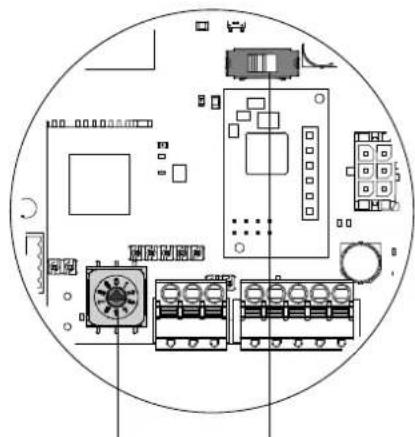
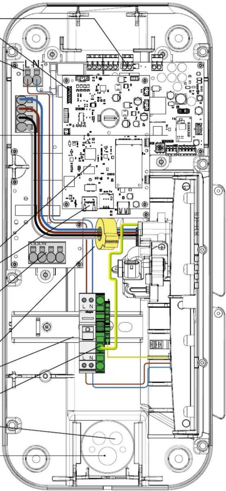
11. Description of the interior
• Electrical composition of the base
Shunt coil terminal block
Interface board ribbon cable (LED/RFID)
Terminal block for mode 2 Type TE or TF socket
natural_image
Top-down schematic of an electronic device layout with components like CPU, memory, and connectors (no text or labels)Operating current selector (see chapter 6. Direct configuration)
3-phase/single-phase selector 3Ph = left 1Ph = right
Control electronic board
RJ45 Ethernet port
Power terminal block:
L3 = grey
L2 = black
L1 = brown
N = blue
6 mA DC detection
13 A C curve circuit breaker -
6 kA: ref. MLN513
(if Mode 2 socket is present)
PE connection
Ethernet cable passage
Power cable passage
• Electrical composition of the front panel

12. Maintenance
12.1. Introduction
The charging station incorporates a set of control parameters to establish a diagnosis during all phases of its operation. The results are visible in the onboard configurator in the "Live Debug" and "Logs" page.
12.2. Normal operation
| Status LED | |
| RFID card accepted Flashing green x 2 | |
| RFID badge rejected Flashing red x 2 | |
| Pending and verifying the authorisation Steady white | |
| Charging station ready without car | Steady green if free access, otherwise flashing green and white |
| Charging in progress Slow flashing green | |
| Charging complete Steady green | |
| Charging station OCPP reserved Steady purple | |
| Local communication lost or not configured (Ethernet/Wifi) Flashing white | |
| Communication with OCPP server lost Steady white |
12.3. Anomaly indicators
| Charging station status Lighting strip | |
| No error | see statuses in chapter12.2 Normal operation |
| Failure of the Mode 3 socket cable (incorrect PP) | flashes red once (1) |
| CP short circuit failure (Status E) | |
| RFID badge rejected flashes red twice (2) | |
| Car overconsumption | flashes red three (3) timesCommunication err |
| Detection of a 6 mA DC fault current | |
| Communication error with the meter flashes red four (4) times | |
| Raised temperature - reduction or interruption of the charging session | flashes red five (5) times |
| M2 socket fuse/circuit breaker open - protection against overcurrent | |
| Critical error: RFID reader failure | steady red |
| Critical error: current selector in an incorrect position | |
| Critical error: detection of stuck contact | |
| Critical error: critical equipment failure | |
| Critical error: 6 mA DC fault current sensor failure | |
| Critical error: current selector at position 9 Return to factory setting (see chapter 6. Direct configuration) | |
| Critical error: electrical power failure | |
| Critical error: incorrect phase sequence used during connection |

In the event of a critical error indicated by a fixed red LED, switch off the charging station for 2 minutes to acknowledge the fault.
12.4. Electrical maintenance
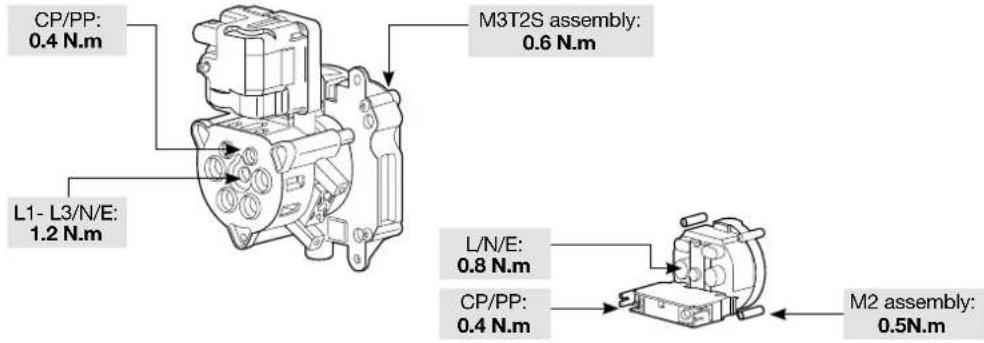
As with any fixed electrical installation product, it is important to check the tightness at the various connection points of the installation during the annual inspection. They must be in phase with the following torques:

Respect the tightening torque; risk of electrical shock.
Tightening torques

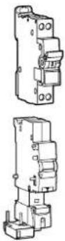
2 N.m circuit breaker
- Technical characteristics
| Environmental conditions | |
| Usage temperature -25°C to +50°C | |
| Storage temperature -35°C to +70°C | |
| Relative humidity 5% to 95% | |
| Protection IP 55 - IK 10 | |
| Maximum altitude of operation 2000 m | |
| Degree of pollution 3 | |
| Surge voltage 4 kV | |
| Electrical characteristics | |
| Voltage 230 V~ / 400 V~ (three-phase version) -15% / +10% | |
| Nominal insulation voltage Ui 250 V~ / 500 V~ | |
| Usage frequency 50/60 Hz +/- 1% | |
| Charging station electrical protection | 40 A circuit breaker, C curve, energy limitation class I2t 3, on a circuit that cannot supply more than 6 kA in short-circuit (or equivalent) |
| Maximum charging current/power Mode 3 T2/T2S socket (depending on version) | 32 A - 7 kW (single-phase version) / 32 A - 22 kW (three-phase version)16 A - 4 kW (single-phase version) / 16 A - 11 kW (three-phase version) |
| Maximum charging current/power Mode 2 TE-TF socket (depending on version) | 10 A - 2300 W |
| Electrical protection rating Class 1 (earth connection) | |
| Overvoltage category 3 | |
| Earth connection diagram TN, TT | |
| Minimum/possible wiring | 10 mm2 in single or multi strand/16 mm2 in multi strand.Only the use of a copper conductor is authorised. |
| Differential protection compatibility | Type A (the 6 mA DC detection is integrated into the charging station, according to standard NF EN 61851-1) |
| Mechanical characteristics | |
| Weight | 6 kg |
| Height | 549 mm |
| Width | 251 mm |
| Depth | 173 mm |
| Packaging characteristics | |
| Weight | 7.9 kg |
| Height | 595 mm |
| Width | 270 mm |
| Depth | 300 mm |
| Classification | |
| Power supply input | Electric Vehicle (EV) power system connected to the AC power supply network (permanently connected) |
| Power supply output | alternating current power system for EV |
| Environmental and usage conditions | indoor and outdoor use |
| Location of | equipment for unrestricted access areas |
| Type of mounting | surface mounting on a wall, posts or equivalent positions and mounting on a on post, column and pipe.Installation in a horizontal position on the ceiling or on the floor is prohibited |
| Category equipment | 1 |
| Charging mode | mode 3 via T2/T2S socket and mode 2 via TE-TF socket (depending on version) |
| Method of electrical connection | connected to plug and cable or permanently connected. |
| Adaptor | no plug adapter can be used between the charging station and the charging cable or between the charging cable and the car |
| Length of cable and cable extension | charging cable extension is not permitted; the charging cable must be in one piece and a maximum length of 10 m |
| External ventilation | not supported |
- RFID reader
| Classification | |
| Frequency band 13.5 MHz | |
| Maximum radiated power 42 dBμA/m (for 13.5 MHz) | |
| Types of badges accepted | - MIFARE classic, 1k/4k; MIFARE DESFire EV1 & EV2 SAM AV3- RFID ISO 14443A / B; ISO15693.- NFC tags 1, 2, 3, 4, 5 |
- Wifi
| Classification | |
| Frequency band 2.4 GHz | |
- Identification of vehicle compatibility according to EN 17186
| Alternating Current EN 62196-2 Type 2 | Plug Socket base | ≤slant 480 V RMS |
Inhaltsverzeichnis
natural_image
Pure technical line drawing of a vertical pipe or rod inside a circle (no text or symbols)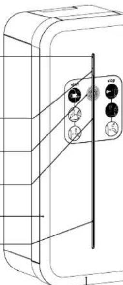
natural_image
Technical line drawing of a dual electrical outlet with two circular connectors (no text or symbols)natural_image
Technical line drawing of a mechanical device with an open lid and internal compartments, showing a black arrow indicating rotation (no text or symbols present)
natural_image
Technical line drawing of a mechanical device with internal components and a close-up inset showing a gear mechanism (no text or symbols)
natural_image
Technical line drawing of a battery pack assembly showing internal compartments and housing (no text or symbols)2.2. Befestigung

natural_image
Simple line drawing of a brick wall and a door with a plus sign, no text or symbols present.
natural_image
Diagram showing a door panel with 'shager' label and a separate electrical box with switches (no text or symbols on the main components)1
natural_image
Illustration of a hand using a tool to cut a circular component with cross marks (no text or symbols)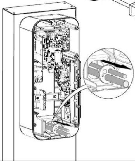
natural_image
Technical line drawing of an internal electronic device with a magnified inset showing internal components (no text or symbols)natural_image
Technical diagram of an electronic device showing internal components and a close-up view of the internal structure (no text or symbols present)natural_image
Cross-sectional diagram of a device showing internal components and a close-up view of a mechanical component (no text or symbols present)
natural_image
Technical line drawing of an electronic device showing internal components and wiring (no text or symbols)2
natural_image
Diagram of a mechanical component with a curved internal structure and directional arrow (no text or symbols)4
natural_image
Diagram of a door switch mechanism showing rotation and clockwise motion (no text or symbols)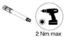
10. Softwarekonfiguration der Ladestation
Vorsichtsmaßnahmen
- XEV1R22T2TE XEV1R22T2TF XEV1R22T2
- Installation
- Ouverture
- Fixation
- Activation du HotSpot Wifi
- Safety advice
- Recommendations
- Opening
- Mounting
- Electrical connection
- Wiring for the stuck contact detection function for ZE Ready
- Wiring for the Input/Output functions
- - Input 1/Input 2
- - Output 1
- Electrical protections for charging stations
- Installation and quality of the earthing according to the EV READY 1.4I label
- Stuck contact detection, according to the ZE READY 1.4I and EV READY 1.4I labels
- Fastening the cable support (optional)
- Direct configuration
- Return to factory setting procedure:
- Finalisation
- First use: Wifi Hotspot
- Activating the Wifi Hotspot
- Charging station software configuration
- Initial precautions
- Introduction
- Web server access
- Via the charging station name (HostName)
- Via its IP address
- Identification page
- Configurator
- Configuration parameters
- OCPP
- Wifi
- Network
- Physical installation
- Physical installation
- Advanced functions
- Smart Charging/ISO15118
- Local access
- SuperUser access
- Standards and Regulations
- Sub-metering
- Live Debug
- Description of the interior
- Maintenance
- Introduction
- Normal operation
- Anomaly indicators
- Electrical maintenance
- Inhaltsverzeichnis
- Befestigung
- Softwarekonfiguration der Ladestation
- Vorsichtsmaßnahmen
Brand : HAGER
Model : XEV1R22T2ER
Category : Car charger