
GASTRO K 1407 CSG A 2D/2D L2 - Fridge GRAM - Free user manual and instructions
Find the device manual for free GASTRO K 1407 CSG A 2D/2D L2 GRAM in PDF.

| Product type | Refrigerator |
| Brand | Gram |
| Model | GASTRO K 1407 CSG A 2D/2D L2 |
| Refrigerant | R290 (propane) |
| Refrigerant quantity | 0.097 kg |
| Global warming potential (GWP) | 3 |
| Climate class | 4 (30°C / 55% HR) |
| Temperature class | M1 (+5°C) |
| Maximum load per shelf | 40 kg |
| Power supply voltage | 230 V ~ 50 Hz |
| Defrosting | Automatic (4 times/24h) + manual |
| Control type | Electronic with LED display |
| Keyboard lock | Yes |
| Door reversal | Yes (reversible) |
| Air filter maintenance | Every 2 weeks |
| Interior cleaning | Mild soapy solution |
| Safety | Child lock, automatic shutdown in case of failure |
| CE compliance | Yes (2014/30/EU, 2009/125/EF) |
| Usage | Storage of food products in non-domestic environment |
| Installation type | Floor-standing, with adjustable feet or casters |
Frequently Asked Questions - GASTRO K 1407 CSG A 2D/2D L2 GRAM
User questions about GASTRO K 1407 CSG A 2D/2D L2 GRAM
0 question about this device. Answer the ones you know or ask your own.
Ask a new question about this device
Download the instructions for your Fridge in PDF format for free! Find your manual GASTRO K 1407 CSG A 2D/2D L2 - GRAM and take your electronic device back in hand. On this page are published all the documents necessary for the use of your device. GASTRO K 1407 CSG A 2D/2D L2 by GRAM.
USER MANUAL GASTRO K 1407 CSG A 2D/2D L2 GRAM
natural_image
Exterior view of a modern stainless steel restaurant with two doors and a control panel (no visible text or symbols)Instructions for use
Bedienungsanweisung
Mode d'emploi
Gebruiksaanwijzing
Bruksanvisning
GRAM

Gram Commercial (CVR-nr. 41423986)
Aage Grams Vej 1
6500 Vojens
Optimizing the energy consumption.... 33
General description....33
Refrigerant / GWP value 34
Climate / temperature class 34
Electrical connection 35
General use 36
Starting up....38
Temperature setting 39
Error codes on the display 39
Troubleshooting 40
User menu 41
Keylock 42
Defrosting....42
Defrost water....42
Power failure 43
Cleaning 43
Changing door hinge side 45
Door/drawer gaskets 46
Long term storage 46
Service 47
Disposal 48
EC-Declaration of conformity 49
EI-diagram / Wiring diagram / Schaltbild 137
Stroomstoring....109
Reiniging 110
Omkeren van de deur 112
Onderhoud 113
Vernietigen....114
natural_image
Technical line drawing of two server rack configurations with heat exchangers and mounting base (no text or symbols)Fig. 1

natural_image
Line drawing of a multi-level kitchen cabinet with drawers and control panel (no text or symbols)Fig. 2
natural_image
Line drawing of a multi-tiered stainless steel kitchen cabinet with wheels and doors (no text or symbols)Fig. 3
natural_image
Line drawing of a cabinet interior with visible internal components and a black arrow pointing to the bottom section (no text or symbols)Fig. 6
Strømsvigt
natural_image
Line drawing of a hand opening a drawer into a cabinet (no text or symbols)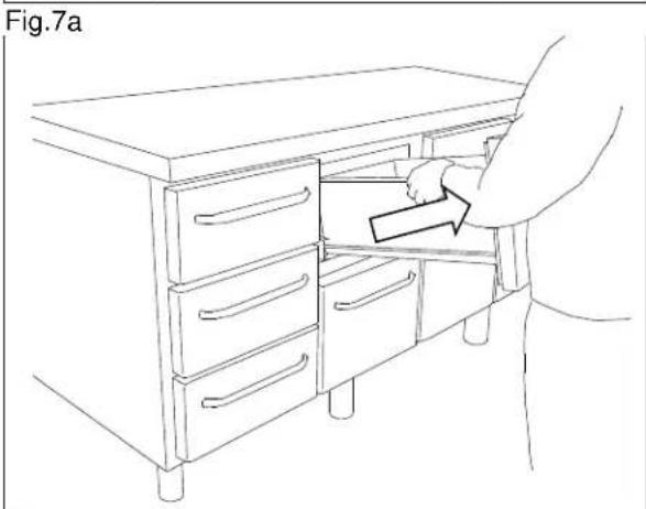
natural_image
Line drawing of a person opening a cabinet drawer with an arrow indicating direction (no text or symbols)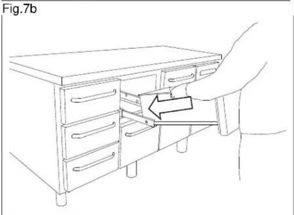
Fig.7c
Vending af dør
ENGLISH
Thank you for choosing a quality product from Gram Commercial.
This manual will advise you how to install, use and maintain your new product.
Before our products leave the factory, they undergo a full function and quality test.
Should you nevertheless experience problems with the product, then contact your local dealer. Gram Commercial representatives and dealers placed all over the world are ready to help you.
Please refer to your dealer for information about the warranty coverage of your new Gram product.
Any warranty is subject to correct use according to specifications in this user manual, where e.g. common maintenance and eventual repairs are carried out by authorized technicians with proper knowledge of the product and only using original spare parts.
Changes in installation and other use of the product than prescribed in this manual, might affect the operation and durability of the product.
The manual is written according to our current technical knowledge. We constantly work on updating this information, and we reserve the right to make technical changes.
Intended use
The product is intended for the storage of foodstuffs in non-household environments but not for the display to or access by customers.
The product is designed for storage at a constant temperature and not be used for chilling down or freezing hot/fresh foodstuff.
The product is only to be used for the purpose for which it has been expressly designed. Any other use could cause that the foodstuff stored in the product is not kept at the correct temperature or even damage the product.
The product is not suited for storing blood plasma, laboratory samples, pharmaceuticals or similar substances.
The manufacturer will not be held liable or responsible for any damage caused by improper, incorrect or unreasonable use of the product.
Safety information
Important
Description of symbols used in this manual.

Warning Lacking observation to these instructions might result in accidents with personal injury.

Important If these instructions are not observed, the product might be damaged or destroyed.
Be aware that Gram Commercial has taken precautions to ensure that the safety of the product is in order.
Please read carefully the following information regarding safety.

It is important, that everyone who are to use or install the product, to have access to this manual.

This appliance is not intended for use by persons with reduced physical, sensory or mental capabilities, or lack of experience and knowledge, unless they have been given supervision or instruction concerning use of the appliance by a person responsible for their safety.

Children should be supervised to ensure that they do not play with the appliance.

The appliance might contain parts with sharp edges in the compressor compartment, and in the inside compartment.

The appliance is not to be transported on a sack truck, there is a danger of loosing the balance, causing danger to persons.

Do not pull the power cord to disconnect the appliance, or when moving the appliance.
Location
When receiving the counter, check the packaging material for damage.
If any damage occurs at the packaging material, it should be considered if the cabinet might have been damaged too. If the damage is substantial, please contact your dealer.
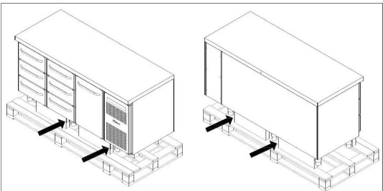
The transport pallet can be removed by loosening the screws that fasten the pallet to the counter.

This task requires at least 2 persons.
natural_image
Technical line drawing of two server rack configurations with heat exchangers and mounting base (no text or symbols)Fig. 1

If the counter has been transported in horizontal position it must stand upright at least 2 hours before it is started to allow the oil from the compressor to run back.

Because of the heavy weight of the counter, the floor might be damaged or scratched when moving the cabinet.
Correct set up gives the most effective operation.
The counter should be located in a dry and adequately ventilated room.
To ensure efficient operation, it may not be placed in direct sunlight or against heat-emitting surfaces. The counter is designed to operate in an ambient temperature between +16°C and +40°C.
Avoid placement of the counter in a chlorine/acid-containing environment (swimming bath etc.) due to risk of corrosion.
The counter and parts of the interior is equipped with a protecting film, which should be removed before use.
Clean the counter with a mild soap solution before use.
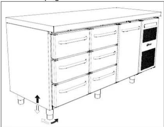
The set up place must be level and horizontal.
For versions with legs, use the adjustable legs to make sure that the counter stands level and upright.
natural_image
Line drawing of a multi-level kitchen cabinet with drawers and control panel (no text or symbols)Fig.2
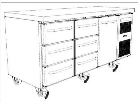
For versions with castors, the locking devices of the two front castors must be activated, when the cabinet is in place. The base must be level, and the counter may not be placed on frames or the like.
natural_image
Line drawing of a multi-tiered kitchen or storage cabinet with wheels and doors (no text or symbols)Fig. 3
Optimizing the energy consumption
- Correct set up gives the most effective operation.
- The product should be located in a dry and adequately ventilated room.
- To ensure efficient operation, it may not be placed in direct sunlight or against heat-emitting surfaces. The product is designed to operate in an ambient temperature between +16°C and +40°C.
- Do not keep the door open for too long.
- Keep the condenser filter clean – to be cleaned at least every 2 weeks.
- Do not set the temperature setpoint too low.
General description
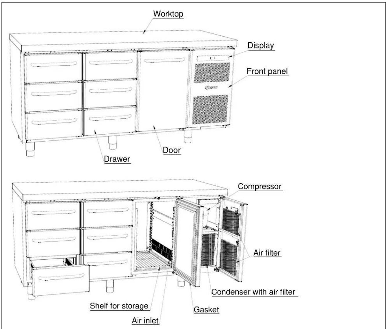
Fig. 4
Refrigerant / GWP value
| Refrigerator counter | Refrigerant | Charge kg | GWP | CO_2 equivalent t |
| K/M 1407 | R290 | 0,097 | 3 | 0,00029 |
| K/M 1807 | R290 | 0,097 | 3 | 0,00029 |
| K/M 2207 | R290 | 0,097 | 3 | 0,00029 |
| Freezer counter | ||||
| F 1407 | R290 | 0,050 | 3 | 0,000150 |
| F 1807 | R290 | 0,059 | 3 | 0,000177 |
| F 2207 | R290 | 0,060 | 3 | 0,000180 |
Climate / temperature class
Products are tested according to the following climate and temperature classes. Information about the product's climate and temperature class can be found at the name plate (see fig.9)
| Climate class |  |
| 3 | 25°C / 60 % RH |
| 4 | 30°C / 55 % RH |
| 5 | 40°C / 40 % RH |
| Temperature class |  |
| L1 | -18°C |
| M1 | +5°C |
Electrical connection
Read the text below thoroughly before electrical connection.

The cabinet is intended for connection to alternating current. The connection voltage (V) and frequency (Hz) are shown on the name plate in the cabinet (see Fig. 9). Only the supplied cord is to be used.

Never use an extension cord for this appliance!
If a wall socket is placed in a longer distance than the length of the supplied power cord, contact an electrician to establish a wall socket within the range of the supplied power cord.

If the product is defective, it must be examined by an authorized technician with proper knowledge of the product during the guarantee period, if it is a product with built-in compressor.
If it is a product connected to an external compressor unit, it must be examined by the company who has connected the product to the unit.
Outside the guarantee period, it is advisable to use the service advised by your dealer. If this is not the case, assistance is required from an authorized technician with proper knowledge of the product.
Always disconnect the power if interruptions in power supply occur, and when electrical parts are removed/put on, and before cleaning and maintenance of the appliance.
Repairing of electrical/technical parts may only be performed by authorized technicians with proper knowledge of the product.
Do not use the appliance before all coverings are installed, so that live or rotating machine parts can not be touched.
The counter is not to be used outdoor.
All earthing requirements stipulated by the local electricity authorities must be observed. The cabinet plug and wall socket should then give correct earthing. If necessary, contact an electrician.

Make sure the appliance is switched off at the socket before service is performed on electrical parts. It is not sufficient to switch off the cabinet by the START/STOP key as there will still be voltage to some electrical parts of the counter.
General use

Do not block vent holes in the front panel.

Do not damage the refrigeration system parts.

During normal operation, some parts of the refrigeration system in the compressor compartment might reach high temperatures, and could therefore cause burns if touching these components.
Do not use electrical devices inside the cabinet.

To ensure correct and efficient air flow in the cabinet, the shaded areas must be kept free of products. (see Fig. 5)

All products to be stored, that are not wrapped or packed, must be covered in order to avoid unnecessary corrosion of the inner parts of the cabinet.

If any controller parameters are changed from default, this could cause that the appliance is not functioning normally, and harmful temperatures could damage products that are kept inside the appliance.

If the appliance is turned off, wait minimum 3 minutes before turning the appliance on again. This is to protect the compressor from damage Maximum loading of wire shelf: 40 kg

Do not store explosive substances such as aerosol cans with flammable propellant in this appliance.
Be aware, if bottles are stored near the air outlet, they may freeze up and break, causing a risk of injury.
Do not pack the cabinet with foods. Allow some space between them to ensure a good airflow.
Moist or fresh foods and those with a strong smell should be wrapped up in a plastic film or packed in a container. Otherwise the food may dry up or give their smell to other foods.
Foods containing acetic acid or yeast should be wrapped up in plastic film. Otherwise they may accelerate corrosion of the evaporator and metal parts, resulting in failure.
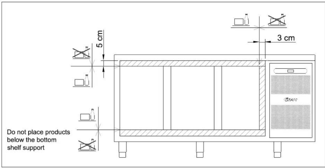
Fig.5
Starting up
Display overview:

* = no function in this product.
Plug in the cabinet.

To start, press the START/STOP key.
During start up, the software version is displayed, followed by the software variant. The cabinet temperature is displayed, when the cabinet starts normal operation.
The cabinet starts with a defrost, which is stopped shortly after, when the system has performed a system check.
To cancel the defrost program, press keys and for more than 3 seconds. is turned off.
To turn off the cabinet, push for more than 3 seconds.
Shortcuts:
| Key combination | Time | Function |
| P + 📋 | >3 seconds | Start or stop manual defrosting |
| 💡 + 1 | >5 seconds | Activation/deactivation of keylock |
| P | - | Displays temperature setpoint |
| P + 1 | >3 seconds | Access to user menu and alarm settings |
Temperature setting
Temperature control:
Press to see the cabinet temperature setting; the display will show the set temperature.
Temperature regulation:
Keep pressed. At the same ^P time, press or .
Each time or is pressed the temperature will change one degree.
When the display shows the desired temperature, let go of the two keys and the setting has been made.
Error codes on the display
| Display code | Description |
| A2 | Local upper alarm LHL is or has been activated |
| A4 | External upper alarm EHL is or has been activated |
| F1 | Room sensor error. In the meantime the counter itself will maintain the set temperature by the memory of the controller. Temperature stability will be affected. Service assistance is required. |
| F2 | Evaporator sensor error. Service assistance is required. The counter will keep running until the error has been mended. |
| F3* | Condenser sensor error. The counter will keep running, until the error has been mended. Service assistance is required. |
| F7* | Indicates that the condenser temperature is too high. The cause might be a clogged condenser, or too high ambient temperature. If the condenser or air filter needs cleaning, the counter must be disconnected at the mains power. Cleaning of the condenser is done with a brush or a vacuum cleaner. The air filter can be removed and cleaned in a dishwasher at max. 50°C. If the ambient temperature is too high, the placement of the counter might be wrong, and an alternative place should be found. Ventilation might help. If this does not help, request service assistance. |
* Applies only to counters with built-in compressor.
Acknowledgement of an alarm:
Acknowledge an alarm: push P
Troubleshooting
Noise:
- If abnormal noise occurs, request service assistance.
- Operating sounds from compressor, condenser fan and interior fan are normal.
- If sheet metal parts, front panels or panels in front of the compressor compartment are making noise, these might be open. Close the panels.
Frosting inside compartment:
- Ambient humidity too high.
- The door is opened too often.
- The door is left open for too long.
- Damaged door gasket.
Poor cooling performance:
- Ambient temperature too high.
- The door is opened too often and/or open for too long.
- The door is left open.
- Damaged door gasket.
• Room temperature setting too high. - Counter too packed with foods - air inlet/outlet blocked.
- Condenser mesh filter is clogged.
- Warm or hot foods inside.
- Defrost in progress. The room temperature may rise temporarily during the defrost cycle, but it will not affect the foods inside.
Some of the foods are frozen:
- Counter too packed with foods - air inlet/outlet blocked.
• Room temperature setting too low.
Condensation around the door:
- Ambient humidity too high.
- The door is not closed tightly.
- Damaged door gasket.
Too high energy consumption:
- Ambient temperature too high.
- The door is opened too often and/or open for too long.
- The door is left open.
- Damaged door gasket.
• Room temperature setting too low. - Counter too packed with foods - air inlet/outlet blocked.
- Condenser mesh filter is clogged.
- Warm or hot foods are brought into the cabinet too often.
- Counter placed in direct sunlight or close to heat-emitting surfaces.
- The default settings have been changed.
User menu
This chapter includes setting of alarm values.
The alarm system is divided into 2 systems. The one system only triggers local alarms, which means that the error codes are only shown at the display.
The other alarm system triggers both alarms at the display, but it also activates the remote alarm outlet. Each alarm system operates independently of each other.
If a change of the setting is required, get access to the menu by pushing for more than 3 seconds. The values are changed by pushing the or keys. The new setting is saved by pushing .To exit the menu, push .
| Menu access P + 1 →I | ↓ | →I | ||
| Local alarm setting | LAL | LhL | °C | Setting the upper alarm limit. At alarm, the display shows: A2 |
| Lhd | min. | Time delay for the upper alarm limit. | ||
| BU | On/off | Activation of buzzer. The buzzer sounds at alarms A1, A2. (1=on / 0=off) | ||
| External alarm setting | EAL | EHL | °C | Setting the upper alarm limit. At alarm, the display shows: A3 |
| ELL | °C | Setting the lower alarm limit. At alarm, the display shows: A4 | ||
| EHd | min. | Time delay for the upper alarm limit. | ||
| ELd | min. | Time delay for lower alarm. | ||
| Temperature offset (sensor calibration) | CAL | CA | K | -5...+5 K |
| Escorting alarm limits | ALL | FAS/ESC | Activation of escorting alarm limits.FAS= fixed limits / ESC = limits following the setpoint | |
| No. of defrosts | dEF | 4 | Number of defrosts in 24 hours. |
Keylock
The keypad can be locked by simultaneously pushing for more than 5 seconds.
lights to indicate that the keys are locked, and a short beep sounds. Now it is not possible to use the keys for temperature setting etc.
The same code is to be used for unlocking the keypad again.
Defrosting
Defrosting is automatically performed 4 times every 24 hours. If the counter is operating under severe load (frequent door opening and frequent replenishment), manual defrosting can become necessary.
Starting manual defrosting: push simultaneously for more than 3 seconds.
The next defrost will occur 6 hours later. ●lights up to indicate a defrosting cycle.
It is possible to change the number of defrosts. See the chapter "User menu" for setting.

Do not use sharp or pointed objects to accelerate the defrosting process.
Defrost water
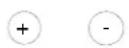
Counters with compressor
Defrost water is led through a pipe, from the evaporator and into a tray behind the condenser. Here, the water is evaporated by heat from the condenser.
Counters connected to a common compressor
The defrost water is led through a pipe to a tray behind the front panel, from where it is evaporated by a heating element.

It is recommended to clean the tray at least once a year. Remember to disconnect the counter before cleaning.
natural_image
Line drawing of a rectangular industrial machine with internal components and a black arrow indicating a component (no text or symbols present)Fig. 6
Power failure
In the event of a power failure, the control remembers the temperature setting and restarts the counter when power is restored. If the power failure persists for some time, the control might revert to the factory setting.
Cleaning
Insufficient cleaning will cause that the counter will not work at optimum performance, or eventually it will be defective.


Before cleaning, the counter should always be disconnected.
Do not flush the counter with water, do not use water jet or steam hose as this may cause short-circuits in the electrical system.
Cleansing agents containing chlorine or compounds of chlorine as well as other corrosive means, are not to be used, as they might cause corrosion to the stainless panels of the cabinet and the evaporator.
The compressor compartment and in particular the condenser must be kept free from dust and dirt. This is best done with a vacuum cleaner and a brush.
The air filters on the condenser and the front panel can be removed and cleaned in a dishwasher at max. 50°C.
For the external maintenance – use stainless steel polish.
The counter should be cleaned internally with a mild soap solution at suitable intervals and checked thoroughly before it is put into operation again.
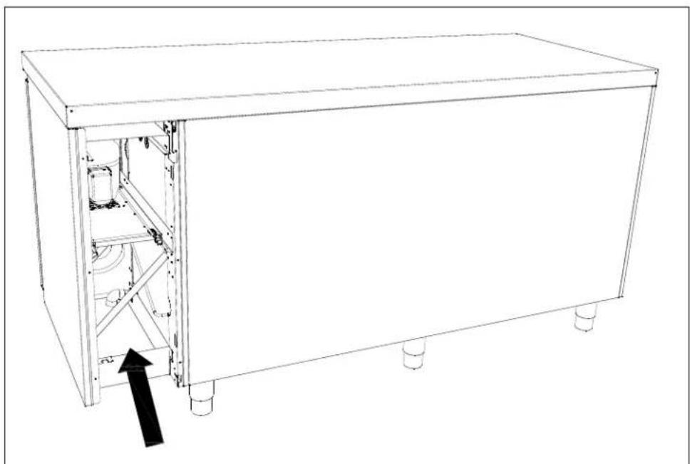
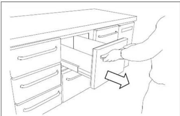
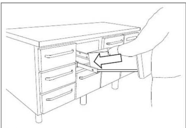
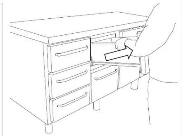
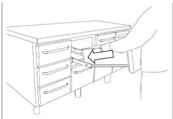
Cleaning of counters with drawers:
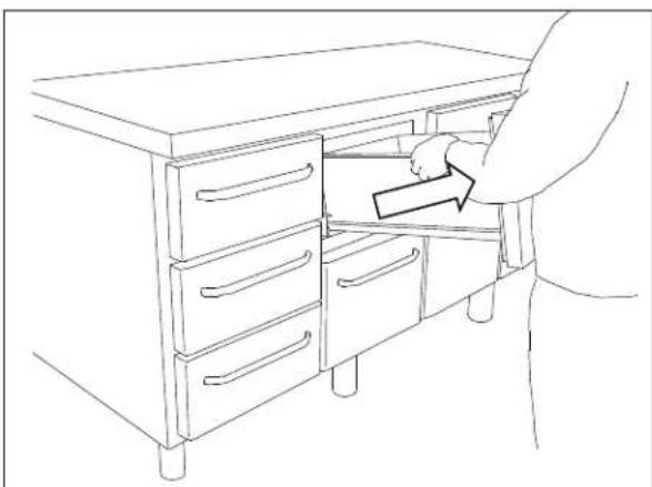
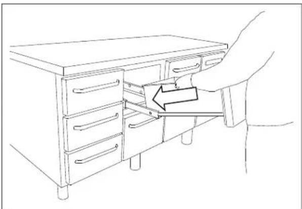
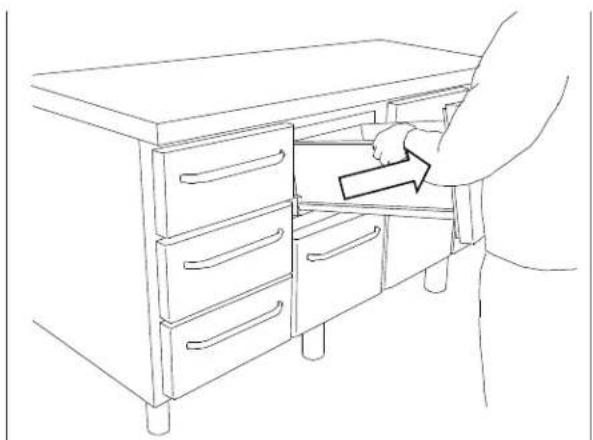
If the counter is equipped with drawers and the bottom, sides or back wall require cleaning, the drawers can be removed as follows (see Fig. 7a,7b,7c):
Pull out the drawer. Lift it up, after which the drawer can be pulled of the extension rails.
After cleaning, the drawer can be replaced. Place the drawer on the outer wheels on the telescopic rails. Lower the drawer into a horizontal position after which it can be pushed into a closed position. The drawer is now securely positioned.
natural_image
Line drawing of a hand opening a drawer into a cabinet (no text or symbols)Fig.7a
natural_image
Line drawing of a person opening a cabinet with drawers, no text or symbols presentFig.7b
natural_image
Line drawing of a hand inserting a drawer into a cabinet handle, with an arrow indicating the fold (no text or symbols present)Fig.7c
765042559 Rev. 000 44
Changing door hinge side
The door can be changed from righthand-hinged to lefthand-hinged or vice-versa.
To do so, proceed as follows:
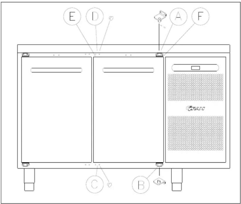
Fig. 8
- Remove the hinge at pos. A.
- Lift off the door.
- Remove the hinge at pos. B.
- Move cover plugs in the cabinet from pos. D to pos. A and from pos. C to pos. B.
- Move the cover plug in the door from pos. D to pos. A, too.
- The hinge previously mounted at pos. A is now mounted at pos. C.
- The door is now placed at the hinge at pos. C.
- The hinge previously mounted at pos. B is now mounted at pos. D and adjusted, so that the door is closing properly. Then tighten the screws.
Door/drawer gaskets
This chapter deals with the importance of a well-functioning gasket.
Gaskets are an important part of a refrigerator/freezer. Gaskets with reduced functionality, reduces the tightness of the counter. Reduced tightness might cause increased humidity, internal icing, an iced up evaporator (leading to reduced refrigeration capacity), and in worst case reduced lifecycle of the counter.

Therefore it is important to be aware of the condition of the gasket. Regular inspection is recommended.
The gasket should be cleaned regularly with a mild soap solution.
If a gasket needs replacement, contact your supplier.
Long term storage
If the counter is taken out of operation, and need to be prepared for long-term storage, clean the inside compartment, the door and door gasket thoroughly with a hot soapy damp cloth. Eventual remnants of food could create mould.
Service
The refrigerating system and the hermetically sealed compressor require no maintenance - they merely must be kept clean.
If refrigeration fails, first investigate whether the unit has been unintentionally disconnected or switched off at the socket, or whether a fuse has blown.
If it is not possible to find the cause of the refrigeration failure, please contact your dealer.
When reporting a malfunction please state the type and serial number (S/N) of the cabinet. This information is found on the name plate, see Fig. 9.
Location of the name plate:
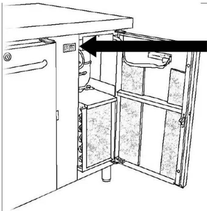
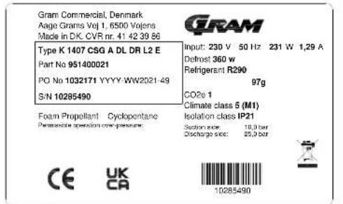
Fig.9
Disposal
Electrical and electronic equipment (EEE) contains materials, components and substances that can be dangerous and harmful to human health and the environment if the waste (WEEE) is not disposed of properly.
Products that are labelled with a “crossed-out wheelie bin” is considered electric and electronic equipment. The crossed-out wheelie bin symbolizes that waste of this type cannot be disposed of with unsorted municipal waste but must be collected separately.
Contact your local dealer when the product needs to be disposed of.
Please be aware of not damaging the refrigeration system and piping when a product is taken out of use. This will prevent the uncontrolled escape of the refrigerant from the refrigeration system.
The below only concerns the United Kingdom.
Disposal of an old cabinet is only available when we are delivering a new one at the same time. Cabinets must be fully defrosted and emptied prior to collection.
Gram recognises that our products for the catering market are considered as WEEE when they become obsolete. To ensure that Gram's responsibilities are handled correctly and environmentally friendly, we are signed up the largest Business to Business compliance scheme in the UK – B2B Compliance
http://www.b2bcompliance.org.uk
B2B Compliance will on our behalf deal with all areas of our responsibilities when collecting and disposing of equipment which fall under the UK WEEE regulations. B2B Compliance can be contacted on telephone number 01691 676124.
EC-Declaration of conformity
Producer
Name: Gram Commercial (CVR-nr. 41423986)
Adress: Aage Grams Vej 1, 6500 Vojens
The product is in compliance with all the essential health- and safety requirements and provisions in:
Directive for Machinery 2006/42/EF
The product is where relevant in compliance with the following other directives:
Electromagnetic Compatibility Directive – 2014/30/EU
Design of energy related products 2009/125/EF
Regulation 2015/1095
Energy labelling directive 2010/30/EU
FCM regulation 10/2011
Regulation 1935/2004
RoHS 2 - 2011/65/EU
RoHS 3 - (EU) 2015/863
Standards
The following standards are used to the extent necessary to comply with the relevant directives:
DS/EN 12100:2011 - Safety of machinery -- General principles for design -- Risk assessment and risk reduction
DS/EN 60335-1:2012 – Household and similar electrical appliances. Safety. General requirements
DS/EN 60335-2-89:2010 – Household and similar electrical appliances. Safety. Particular requirements for commercial refrigerating appliances with an incorporated or remote refrigerant condensing unit or compressor
Person
Company: Gram Commercial (CVR-nr. 41423986)
responsible for
Adress: Aage Grams Vej 1
technical dossier
Name: John Lund
Signature
Vojens 01/12-2021
R&D Manager

UKCA-Declaration of conformity
Producer Name: Gram Commercial (CVR-nr. 41423986)
Address: Aage Grams Vej 1, 6500 Vojens
Directives The product is in compliance with all the essential health- and safety requirements and provisions in:
Directive for Machinery 2006/42/EF
The product is where relevant in compliance with the following other directives:
Electromagnetic Compatibility Directive – 2014/30/EU
Design of energy related products 2009/125/EF
Regulation 2015/1095
FCM regulation 10/2011
Regulation 1935/2004
RoHS 2 - 2011/65/EU
RoHS 3 - (EU) 2015/863
Standards The following standards are used to the extent necessary to comply with the relevant directives:
EN 12100:2011 - Safety of machinery -- General principles for design -- Risk assessment and risk reduction
EN 60335-1:2012 – Household and similar electrical appliances. Safety. General requirements
EN 60335-2-89:2010 – Household and similar electrical appliances. Safety. Particular requirements for commercial refrigerating appliances with an incorporated or remote refrigerant condensing unit or compressor.
UK - Authorized Company: Hoshizaki UK Branch, 2 The Technology Centre, Swanley, Kent BR8 7AG
Representative Name: Branch Manager Simon Frost
Responsible Company: Gram Commercial (CVR-nr. 41423986)
Technical File Name: R&D Manager John Lund
DEUTSCH
natural_image
Technical line drawing of two server rack units with heat exchangers and mounting base (no text or symbols)Fig. 1

natural_image
Line drawing of a multi-level kitchen or oven unit with drawers and control panel (no text or symbols)Fig. 2
natural_image
Line drawing of a multi-tiered industrial cabinet with wheels and doors (no text or symbols)Fig.3
765042559 Rev. 000 54
natural_image
Line drawing of a rectangular electronic device with internal components and a black arrow pointing to a component (no text or symbols)Fig. 6
Stromausfall
natural_image
Line drawing of a hand opening a drawer into a cabinet (no text or symbols)Fig.7a

natural_image
Line drawing of a person inserting a box into a cabinet (no text or symbols)Fig.7b
natural_image
Line drawing of a hand inserting a drawer into a cabinet (no text or symbols)Fig.7c
Türdichtungen
natural_image
Technical line drawing of a cabinet interior with an open door and internal compartments (no text or symbols)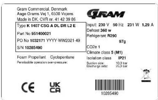
Fig.9
Entsorgung
FRANÇAIS
natural_image
Technical line drawings of two server rack structures with heat exchangers and mounting base (no text or symbols)Fig. 1

natural_image
Line drawing of a multi-level kitchen cabinet with drawers and doors, showing directional arrows indicating movement (no text or symbols)Fig. 2
natural_image
Line drawing of a multi-tiered stainless steel kitchen cabinet with wheels and doors (no text or symbols)Fig. 3
natural_image
Line drawing of a rectangular industrial machine with internal components and a black arrow indicating a component (no text or symbols present)Fig. 6
Panne de courant
natural_image
Line drawing of a person opening a drawer into a cabinet (no text or symbols)Fig.7a

natural_image
Line drawing of a hand placing a drawer into a cabinet (no text or symbols)Fig.7b

natural_image
Line drawing of a hand inserting a drawer into a cabinet (no text or symbols)Fig.7c
natural_image
Line drawing of a cabinet interior with an open door and internal compartments (no text or symbols)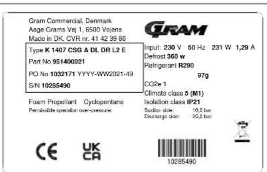
Fig. 9
Enlèvement
Directive machines 2006/42/EF
Regulation 2015/1095
FCM regulation 10/2011
Réglementation 1935/2004
RoHS 2 - 2011/65/EU
RoHS 3 - (EU) 2015/863
dossier technique Nom: John Lund
Signature Vojens 01/12-2021 R&D Manager
John Taul
NEDERLANDS
natural_image
Technical line drawing of two modular server or storage units with heat exchangers and mounting base (no text or symbols)Fig. 1.

natural_image
Line drawing of a multi-level kitchen cabinet with drawers and control panel (no text or symbols)Fig. 2.
natural_image
Line drawing of a multi-compartment kitchen cabinet with wheels and drawers (no text or symbols)Fig. 3.
765042559 Rev. 000 97
natural_image
Line drawing of a rectangular industrial machine with internal components and a black arrow indicating a component (no text or symbols present)Fig. 6
Stroomstoring
natural_image
Line drawing of a hand opening a drawer into a cabinet (no text or symbols)Fig.7a
natural_image
Line drawing of a person opening a cabinet drawer with drawers, no text or symbols presentFig.7b
natural_image
Line drawing of a hand inserting a drawer into a cabinet (no text or symbols)Fig.7c
Omkeren van de deur
Fig.8
natural_image
Technical line drawing of two server rack units with heat exchangers and mounting base (no text or symbols)Fig. 1

natural_image
Line drawing of a multi-level kitchen cabinet with drawers and control panel (no text or symbols)Fig. 2
natural_image
Line drawing of a multi-level kitchen cabinet with wheels and doors, no text or symbols presentFig. 3
natural_image
Line drawing of a rectangular electronic device with internal components and a black arrow pointing to a component (no text or symbols)Fig. 6
Strömavbrott
natural_image
Line drawing of a hand opening a drawer into a cabinet (no text or symbols)Fig.7a
natural_image
Line drawing of a person opening a cabinet drawer with an arrow indicating direction (no text or symbols)Fig.7b

natural_image
Line drawing of a hand inserting a drawer into a cabinet (no text or symbols)Fig.7c
Vändning av dörr
Adress: Aage Grams Vej 1
dossier
Namn: John Lund
Signatur
Vojens 01/12-2021
R&D Manager
John Tewl
El-diagram / Wiring diagram / Schaltbild
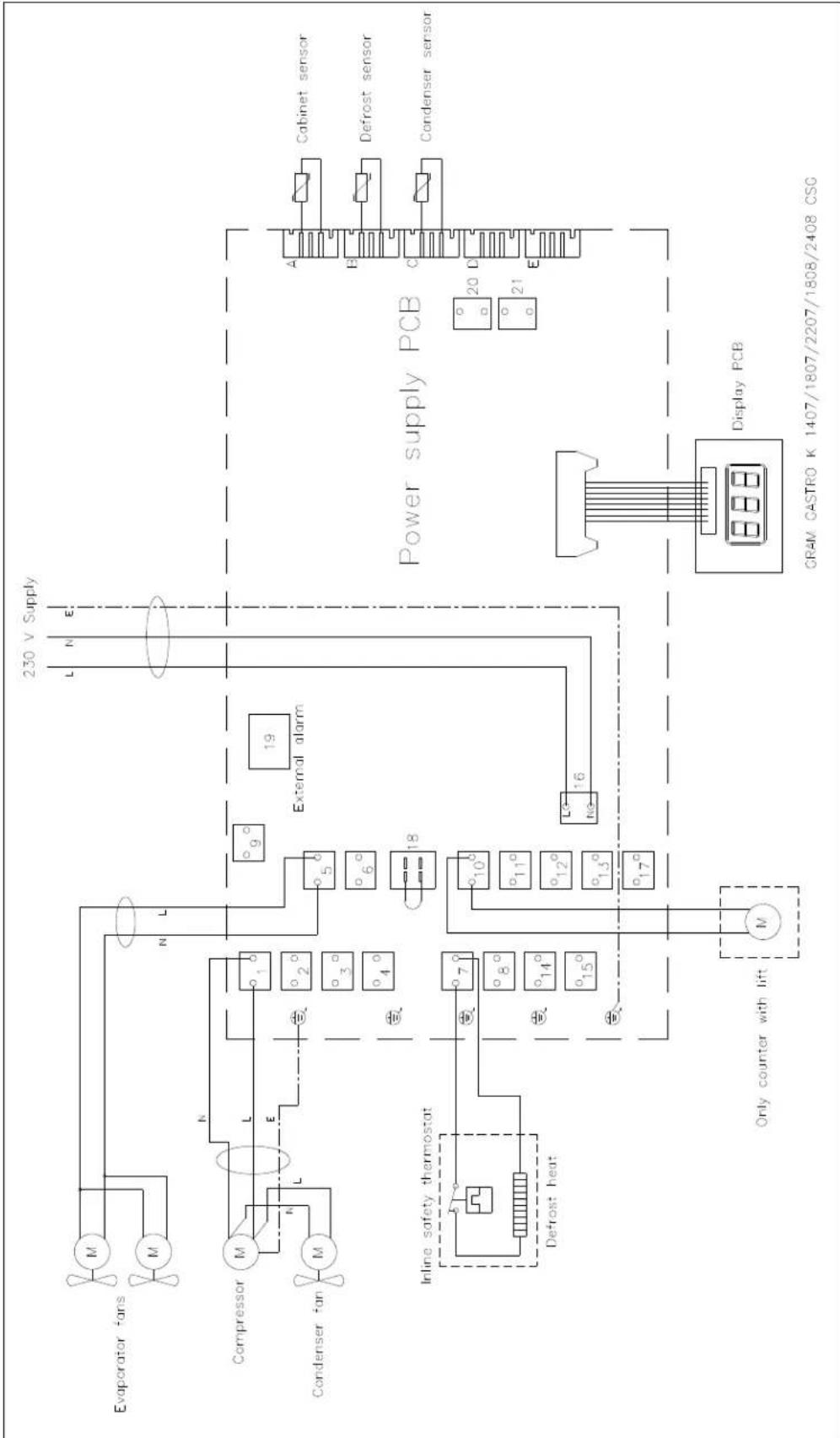
flowchart
graph TD
    A["Evaporator fans"] --> B["Compressor"]
    B --> C["Condenser fan"]
    C --> D["Power supply PCB"]
    D --> E["Display PCB"]
    E --> F["Only counter with lift"]
    F --> G["Defrost heat"]
    G --> H["Inline safety thermostat"]
    H --> I["External alarm"]
    I --> J["230 V Supply"]
    J --> K["Cabinet sensor"]
    J --> L["Defrost sensor"]
    J --> M["Condenser sensor"]
    N["18°"] --> O["19°"]
    O --> P["16°"]
    P --> Q["15°"]
    Q --> R["14°"]
    R --> S["13°"]
    S --> T["12°"]
    T --> U["11°"]
    U --> V["10°"]
    V --> W["9°"]
    W --> X["8°"]
    X --> Y["7°"]
    Y --> Z["6°"]
    Z --> AA["5°"]
    AA --> AB["4°"]
    AB --> AC["3°"]
    AC --> AD["L"]
    AD --> AE["N"]
    AE --> AF["L"]
    AF --> AG["L"]
    AG --> AH["N"]
    AH --> AI["L"]
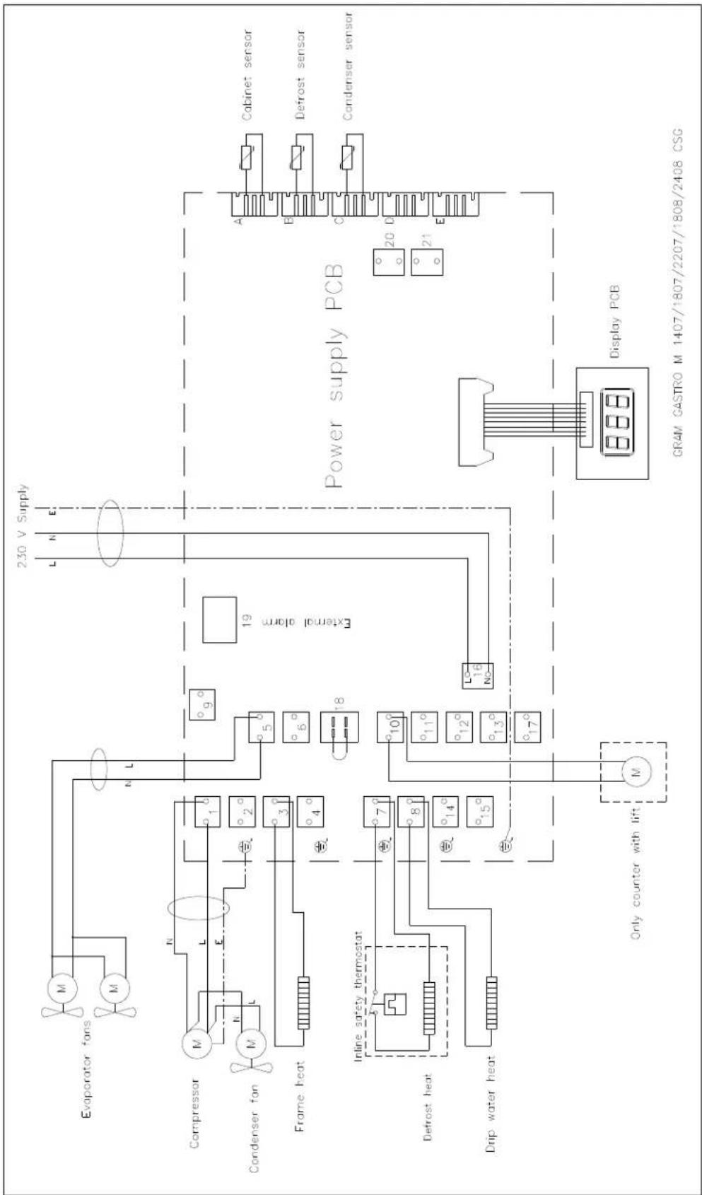
flowchart
graph TD
    A["Evaporator fans"] --> B["Compressor"]
    B --> C["Condenser fan"]
    C --> D["Frame heat"]
    D --> E["Inline safety thermostat"]
    E --> F["Defrost heat"]
    F --> G["Drip water heat"]
    G --> H["Only counter with lift"]
    H --> I["Display PCB"]
    I --> J["Cabinet sensor"]
    I --> K["Defrost sensor"]
    I --> L["Condenser sensor"]
    style A fill:#f9f,stroke:#333
    style B fill:#ccf,stroke:#333
    style C fill:#cfc,stroke:#333
    style D fill:#fcc,stroke:#333
    style E fill:#cff,stroke:#333
    style F fill:#ffc,stroke:#333
    style G fill:#cfc,stroke:#333
    style H fill:#fcc,stroke:#333
    style I fill:#ffc,stroke:#333
    style J fill:#cfc,stroke:#333
    style K fill:#cfc,stroke:#333
    style L fill:#cfc,stroke:#333
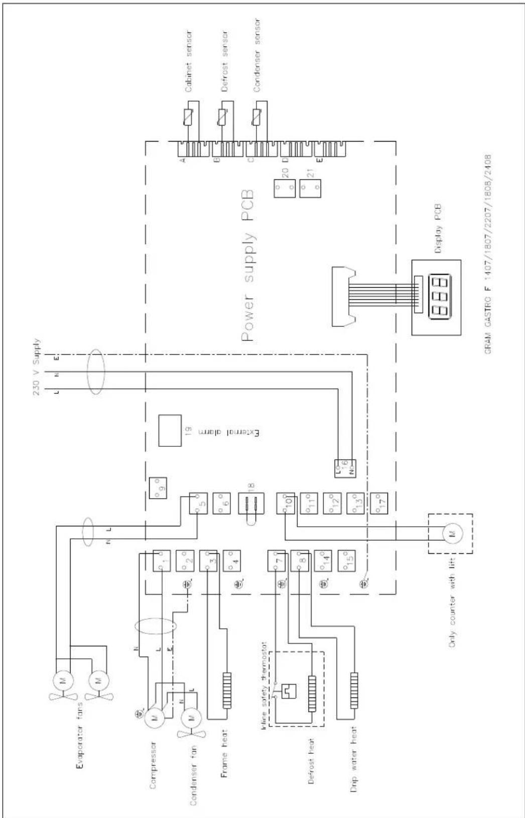
flowchart
graph TD
    A["Evaporator fans"] --> B["Compressor"]
    B --> C["Condenser fan"]
    C --> D["Frame heat"]
    D --> E["In-line safety thermostat"]
    E --> F["Defrost heat"]
    F --> G["Drip water heat"]
    G --> H["Only counter with lift"]
    H --> I["Display PCB"]
    I --> J["Power supply PCB"]
    J --> K["Cabinet sensor"]
    J --> L["Defrost sensor"]
    J --> M["Condenser sensor"]
    K --> N["230 V Supply"]
    L --> N
    M --> N
    style A fill:#f9f,stroke:#333
    style B fill:#ccf,stroke:#333
    style C fill:#cfc,stroke:#333
    style D fill:#fcc,stroke:#333
    style E fill:#cff,stroke:#333
    style F fill:#ffc,stroke:#333
    style G fill:#cfc,stroke:#333
    style H fill:#fcc,stroke:#333
    style I fill:#ffc,stroke:#333
    style J fill:#cfc,stroke:#333
    style K fill:#fcc,stroke:#333
    style L fill:#cfc,stroke:#333
    style M fill:#fcc,stroke:#333
- Strømsvigt
- Vending af dør
- ENGLISH
- Intended use
- Safety information
- Important
- Please read carefully the following information regarding safety.
- Location
- Optimizing the energy consumption
- General description
- Refrigerant / GWP value
- Climate / temperature class
- Electrical connection
- General use
- Starting up
- Temperature setting
- Temperature control:
- Temperature regulation:
- Error codes on the display
- Acknowledgement of an alarm:
- Troubleshooting
- Noise:
- Frosting inside compartment:
- Poor cooling performance:
- Some of the foods are frozen:
- Condensation around the door:
- Too high energy consumption:
- User menu
- Keylock
- Defrosting
- Defrost water
- Counters with compressor
- Counters connected to a common compressor
- Power failure
- Cleaning
- Cleaning of counters with drawers:
- Changing door hinge side
- Door/drawer gaskets
- Long term storage
- Service
- Disposal
- The below only concerns the United Kingdom.
- EC-Declaration of conformity
- Producer
- Standards
- Person
- responsible for
- technical dossier
- Signature
- UKCA-Declaration of conformity
- DEUTSCH
- Stromausfall
- Türdichtungen
- Entsorgung
- FRANÇAIS
- Panne de courant
- Enlèvement
- NEDERLANDS
- Stroomstoring
- Omkeren van de deur
- Strömavbrott
- Vändning av dörr
- Signatur
Brand : GRAM
Model : GASTRO K 1407 CSG A 2D/2D L2
Category : Fridge