DWE5615 - Saw DEWALT - Free user manual and instructions
Find the device manual for free DWE5615 DEWALT in PDF.

User questions about DWE5615 DEWALT
0 question about this device. Answer the ones you know or ask your own.
Ask a new question about this device
Download the instructions for your Saw in PDF format for free! Find your manual DWE5615 - DEWALT and take your electronic device back in hand. On this page are published all the documents necessary for the use of your device. DWE5615 by DEWALT.
USER MANUAL DWE5615 DEWALT
Application Information
| ACCESSORY | 7"Type 27 Grinding Wheel | 9"Type 27 Grinding Wheel | 6"Abrasive Cup Stone | 5"Abrasive Cup Stone | 4"Abrasive Cup Stone | 6"Wire Wheel | 4"Wire Cup Brush | 6"Wire Cup Brush | 7"Diamond Cup Wheel | 7"Sanding Flap Disc | 7"Sanding Disc | 9"Sanding Disc | 7"Type 1 Diamond or Abrasive Wheel |
| D28493N5000 rpm | |||||||||||||
| D28494S6000 rpm | |||||||||||||
| D28494N6000 rpm | |||||||||||||
| D28474W8000 rpm | |||||||||||||
| REQUIRED GUARD | Must Be Used with D284937 | Must Be Used with D284939 | Must Be Used with D284936 | Must Be Used with D284936 | Must Be Used with D284934 | Must Be Used with D284937 /D284939 | Must Be Used with D284937 /D284939 | Must Be Used with D284937 /D284939 | Must Be Used with D284937 | Must Be Used with D284937 | Must Be Used with D284931 | ||
| OPTIMAL CAPABLE CAN NOT BE USED | |||||||||||||
DEWALT Industrial Tool Co., 701 East Joppa Road, Baltimore, MD 21286 (APR04-CD-1)
Form No. 399080-03
D28474, D28493, D28493G, D28494, D28494G, D28499, D28497
Copyright © 2003
The following are trademarks for one or more DEWALT power tools: the yellow and black color scheme; the "D" shaped air intake grill; the array of pyramids on the handgrip; the kit box configuration; and the array of lozenge-shaped humps on the surface of the tool.
Questions? See us on the World Wide Web at www.dewalt.com
INSTRUCTION MANUAL
GUIDE D'UTILISATION
IF YOU HAVE ANY QUESTIONS OR COMMENTS ABOUT THIS OR ANY DEWALT TOOL, CALL US TOLL FREE AT:
1-800-4-DEWALT (1-800-433-9258)
SAVE THESE INSTRUCTIONS!
General Safety Instructions
WARNING! Read and understand all instructions. Failure to follow all instructions listed below, may result in electric shock, fire and/or serious personal injury.
SAVE THESE INSTRUCTIONS
WORK AREA
Keep your work area clean and well lit. Cluttered benches and dark areas invite accidents.
Do not operate power tools in explosive atmospheres, such as in the presence of flammable liquids, gases, or dust. Power tools create sparks which may ignite the dust or fumes.
Keep bystanders, children, and visitors away while operating a power tool. Distractions can cause you to lose control. ELECTRICAL SAFETY
Grounded tools must be plugged into an outlet properly installed and grounded in accordance with all codes and ordinances. Never remove the grounding prong or modify the plug in any way. Do not use any adapter plugs. Check with a qualified electrician if you are in doubt as to whether the outlet is properly grounded. If the tools should electrically malfunction or break down, grounding provides a low resistance path to carry electricity away from the user. This tool may use grounded construction (3 prong plug) to provide a means to
transfer electrical energy safely away from the user in the event the tool electrically malfunctions, breaks down, or the tool case becomes live. Damage to, or loss of, one of the 3 plug blades; damage to the plug or cord, or failure to have the tool plugged into a verified and continuously grounded electrical system, may result in electric shock, serious injury, or death. To avoid these risks of injury, the tool must, at all times, be maintained and in proper working order (cord, plug blades) and plugged into a continuously grounded electrical system. (See also "Cleaning" in the Maintenance section, page 15.) Applicable only to Class I (grounded) tools.
▲ Double insulated tools are equipped with a polarized plug (one blade is wider than the other.) This plug will fit in a polarized outlet only one way. If the plug does not fit fully in the outlet, reverse the plug. If it still does not fit, contact a qualified electrician to install a polarized outlet. Do not change the plug in any way. Double insulation ℃luminates the need for the three wire grounded power cord and grounded power supply system. Applicable only to Class II (double insulated) tools.
Avoid body contact with grounded surfaces such as pipes, radiators, ranges and refrigerators. There is an increased risk of electric shock if your body is grounded.
A Don't expose power tools to rain or wet conditions. Water entering a power tool will increase the risk of electric shock.
Do not abuse the cord. Never use the cord to carry the tools or pull the plug from an outlet. Keep cord away from heat, oil, sharp edges or moving parts. Replace damaged cords immediately. Damaged cords increase the risk of electric shock.
When operating a power tool outside, use an outdoor extension cord marked "W-A" or "W." These cords are rated for outdoor use and reduce the risk of electric shock.
Minimum Gage for Cord Sets
Volts Total Length of Cord in Feet
120V 0-25 26-50 51-100 101-150
Ampere Rating
More Not more AWG
Than Than
12 - 16 14 12 Not Recommended
PERSONAL SAFETY
⚠️ Stay alert, watch what you are doing and use common sense when operating a power tool. Do not use tool while tired or under the influence of drugs, alcohol, or medication. A moment of inattention while operating power tools may result in serious personal injury.
▲ Dress properly. Do not wear loose clothing or jewelry. Contain long hair. Keep your hair, clothing, and gloves away from moving parts. Loose clothes, jewelry, or long hair can be caught in moving parts. Air vents often cover moving parts and should also be avoided.
Avoid accidental starting. Be sure switch is off before plugging in. Carrying tools with your finger on the switch or plugging in tools that have the switch on invites accidents.
Remove adjusting keys or wrenches before turning the tool on. A wrench or a key that is left attached to a rotating part of the tool may result in personal injury.
Do not overreach. Keep proper footing and balance at all times. Proper footing and balance enables better control of the tool in unexpected situations.
Use safety equipment. Always wear eye protection. Dust mask, non-skid safety shoes, hard hat, or hearing protection must be used for appropriate conditions.
TOOL USE AND CARE
Use clamps or other practical way to secure and support the workpiece to a stable platform. Holding the work by hand or against your body is unstable and may lead to loss of control.
Do not force tool. Use the correct tool for your application. The correct tool will do the job better and safer at the rate for which it is designed.
Do not use tool if switch does not turn it on or off. Any tool that cannot be controlled with the switch is dangerous and must be repaired.
A Disconnect the plug from the power source before making any adjustments, changing accessories, or storing the tool. Such preventative safety measures reduce the risk of starting the tool accidentally.
Store idle tools out of reach of children and other untrained persons. Tools are dangerous in the hands of untrained users.
Maintain tools with care. Keep cutting tools sharp and clean. Properly maintained tools, with sharp cutting edges are less likely to bind and are easier to control.
Check for misalignment or binding of moving parts, breakage of parts, and any other condition that may affect the tools operation. If damaged, have the tool serviced before using. Many accidents are caused by poorly maintained tools.
Use only accessories that are recommended by the manufacturer for your model. Accessories that may be suitable for one tool may become hazardous when used on another tool.
SERVICE
▲ Tool service must be performed only by qualified repair personnel. Service or maintenance performed by unqualified personnel could result in a risk of injury.
When servicing a tool, use only identical replacement parts. Follow instructions in the Maintenance section of this manual. Use of unauthorized parts or failure to follow Maintenance instructions may create a risk of electric shock or injury.
Specific Safety Rules for Grinders
▲ Always use proper guard with grinding wheel. A guard protects operator from broken wheel fragments and wheel contact.
Accessories must be rated for at least the speed recommended on the tool warning label. Wheels and other accessories running over rated speed can fly apart and cause injury. Refer to the table below. Accessory ratings must always be above tool speed as shown on tool nameplate.
NOTE: The rated no load tool speed is printed on the name plate and embossed on the gear case.
| Rated no(no load)Tool Speed | MinimumAccessoryRating |
| 5000 RPM | 5500 RPM |
| 6000 RPM | 6600 RPM |
| 8000 RPM | 8500 RPM |
Hold tool by insulated gripping surfaces when performing an operation where the cutting tool may contact hidden wiring or its own cord. Contact with a "live" wire will make exposed metal parts of the tool "live" and shock the operator.
▲ Before using, inspect recommended accessory for cracks or flaws. If such a crack or flaw is evident, discard the accessory. The accessory should also be inspected whenever you think the tool may have been dropped. Flaws may cause wheel breakage.
When starting the tool with a new or replacement wheel, a new or replacement wire brush installed, or if you are unsure of the condition of the wheel, hold the tool in a well protected area and let it run for one minute. If the wheel has an undetected crack or flaw, it should burst in less than one minute. If the wire brush has loose wires, they will be detected. Never start the tool with a person in line with the wheel. This includes the operator.
In operation, avoid bouncing the wheel or giving it rough treatment. If this occurs, stop the tool and inspect the wheel for cracks and flaws.
▲ Direct sparks away from operator, bystanders or flammable materials. Sparks may be produced while using a sander or grinder. Sparks may cause burns or start fires.
Always use side handle. Tighten the handle securely. The side handle should always be used to maintain control of the tool at all times.
▲ Clean out your tool often, especially after heavy use. Dust and grit containing metal particles often accumulate on interior surfaces and could create a risk of serious injury, electric shock or electrocution.
Do not operate this tool for long periods of time. Vibration caused by tool action may be harmful to your hands and arms. Use gloves to provide extra cushion and limit exposure by taking frequent rest periods.
WARNING: Some dust created by power sanding, sawing, grinding, drilling, and other construction activities contains chemicals known to cause cancer, birth defects, or other reproductive harm. Some examples of these chemicals are:
- lead from lead-based paints,
• crystalline silica from bricks and cement and other masonry products, and
• arsenic and chromium from chemically-treated lumber (CCA).
Your risk from these exposures varies, depending on how often you do this type of work. To reduce your exposure to these chemicals: work in a well ventilated area, and work with approved safety equipment, such as those dust masks that are specially designed to filter out microscopic particles.
- Avoid prolonged contact with dust from power sanding, sawing, grinding, drilling, and other construction activities. Wear protective clothing and wash exposed areas with soap and water. Allowing dust to get into your mouth, eyes, or lay on the skin may promote absorption of harmful chemicals.
WARNING: Use of this tool can generate and/or disburse dust, which may cause serious and permanent respiratory or other injury. Always use NIOSH/OSHA approved respiratory protection appropriate for the dust exposure. Direct particles away from face and body.
CAUTION: Use extra care when grinding into a corner because a sudden, sharp movement of the grinder may be experienced when the wheel contacts a secondary surface.
CAUTION: Wear appropriate personal hearing protection during use. Under some conditions and duration of use, noise from this product may contribute to hearing loss.
- The label on your tool may include the following symbols. The symbols and definitions are as follows:
V.....volts
Hz ...... hertz
min......minutes
......direct current
□ Class II Construction
A ......safety alert symbol
A ......amperes
W......watts
\~ ......alternating current
n_0 ......no load speed
earthing terminal
.../min.....revolutions
per minute
FAMILIARIZATION
Large Angle Grinders and Large Angle Sanders are designed for heavy material removal in extended use applications. The following grinders and sanders are described in this manual:
D28474 7" Angle Grinder double insulated 8,000 rpm
D28493 9" Angle Grinder double insulated 5,000 rpm
D28493G 9" Angle Grinder grounded 5,000 rpm
D28494 7"/9" Angle Grinder double insulated 6,000 rpm
D28494G 7"/9" Angle Grinder grounded 6,000 rpm
D28497 7"/9" Angle Sander grounded 6,000 rpm
D28499 7"/9" Angle Grinder double insulated 6,000 rpm
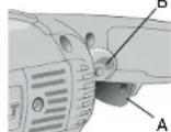
Components
A. Trigger Switch B. Lock On Button
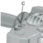
C. Spindle Lock D. Side Handle
E. Spindle F. Soft Mount
G. Top Bumper
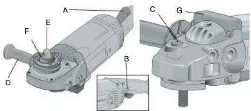
text_image
Technical diagram of a mechanical device with labeled parts A through G, including a zoomed-in detail view.Features
SWITCH
The tool is controlled by a trigger switch (A). A lock-on button (B) provides increased comfort in extended use applications.
ROTATING REAR HANDLE (D28499 ONLY)
The rear handle can be positioned 30°, 60°, and 90° left and right of center position.
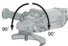
ROTATING GEAR CASE (D28474, D28493, D28494, D28497)
For applications in which a tool will be dedicated for uses in edge grinding and finishing work, the gear case may be rotated 90° left or right of its original position. See page 9 for instructions on rotating the gear case.
MULTIPLE SIDE HANDLE POSITIONS
The side handle can be properly positioned in five locations based on personal preference and application. The side handle must be used at all times to maintain proper control of the tool.
TOP BUMPER
The gear case top bumper may wear with use. The bumper can be replaced with part number 397711-00 available at extra cost from DEWALT authorized service centers. Replacement should be performed by DEWALT authorized service centers or qualified service personnel.
SPINDLE LOCK
The spindle lock pin is provided to prevent the spindle from rotating when installing or removing wheels. Operate the spindle lock pin only when the tool is turned off and unplugged from the power
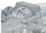
Sanding Flap Discs
text_image
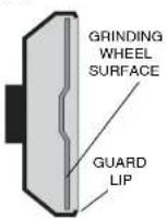
soft mount Type 27 guard D284937/D284939 hubbed sanding flap disc soft mount Type 27 guard D284937/D284939 backing flange 54339-00 non-hubbed sanding flap disc clamp nut 22191-00NOTE: Wheel size must match guard size; i.e., a new 7" wheel may not be used with a 9" guard. The bottom surface of wheel must be inside the bend of the guard lip.
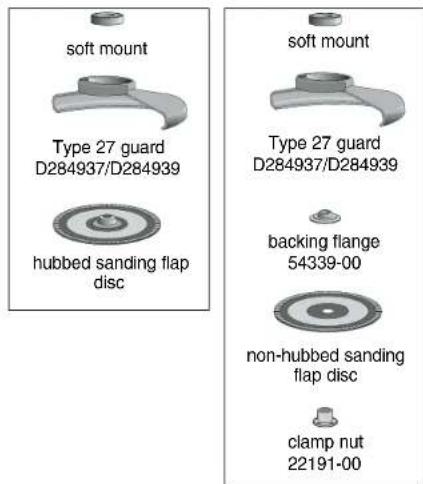
Grinding Wheels
text_image
soft mount Type 27 guard D284937/D284939 Type 27 hubbed wheel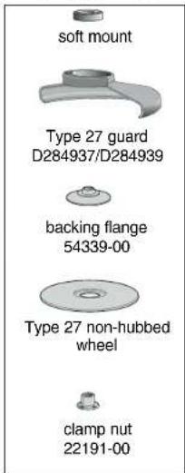
text_image
soft mount Type 27 guard D284937/D284939 backing flange 54339-00 Type 27 non-hubbed wheel clamp nut 22191-00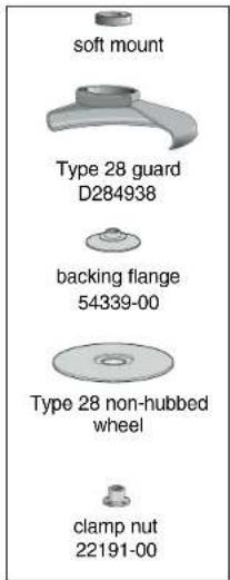
text_image
soft mount Type 28 guard D284938 backing flange 54339-00 Type 28 non-hubbed wheel clamp nut 22191-00Sanding Discs

text_image
soft mount rubber backing pad DW4947 sanding disc clamp nut included with D4947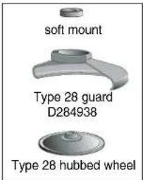
text_image
soft mount Type 28 guard D284938 Type 28 hubbed wheelTE: Wheel size must match guard size; i.e., a new 7" wheel may not be used with a guard. The bottom surface of wheel must be inside the bend of the guard lip.
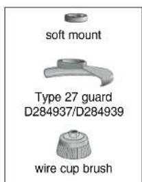
Wire Wheels
text_image
soft mount Type 27 guard D284937/D284939 wire cup brushFlaring Cup Stones
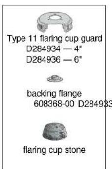
text_image
Type 11 flaring cup guard D284934 — 4" D284936 — 6" backing flange 608368-00 D284933 flaring cup stoneCutting Wheels
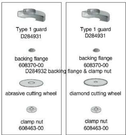
text_image
Type 1 guard D284931 backing flange 608370-00 D284932 backing flange & clamp nut abrasive cutting wheel clamp nut 608463-00 Type 1 guard D284931 backing flange 608370-00 dliamond cutting wheel clamp nut 608463-00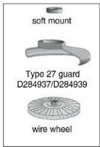
text_image
soft mount Type 27 guard D284937/D284939 wire wheelNOTE: Wheel size must match guard size; i.e., a 7" wheel may not be used with a 9" guard.
source. To engage the lock, depress the spindle lock button (C) and rotate the spindle until you are unable to rotate it further.
CAUTION: Never depress the spindle lock button while the grinder is running. Never turn on the grinder while the spindle lock button is depressed. Damage to your tool or personal injury may result.
SOFT MOUNT
The grinder is equipped with a soft mount, enabling easy wheel installation and removal.
Accessories and Attachments
It is important to choose the correct guards, backing pads and flanges to use with grinder accessories. See the chart on pages 5–7 for information on choosing the correct accessories.
CAUTION: Accessories must be rated for at least the speed recommended on the tool warning label. Wheels and other accessories running over rated speed can fly apart and cause injury. Accessory ratings must always be above tool speed as shown on tool nameplate.
ATTACHMENTS
Attachments designed specifically for this grinder can be purchased through DEWALT dealers and DEWALT Factory Service centers.
D284939 9" Type 27 guard
D284948 9" Type 28 guard
D284937 7" Type 27 guard
D284936 6" Type 11 Flaring cup guard with flange
D284934 4" Type 11 Flaring cup guard with flange
D284933 Type 11 Flaring cup wheel backing flange
D284932 Type 1 Flange set
D284931 7" Type 1 Guard
054339-00 Grinding backing flange
22191-00 Clamp nut
61820-01 Wheel Wrench
445928-01 Soft mount spindle protector
397711-00 Top gear case bumper
ASSEMBLY AND ADJUSTMENTS
Attaching the Side Handle
To install the side handle, thread the handle into one of the five positions listed below and tighten securely by turning clockwise.
- Two front positions: Forward handle positions are designed for optimized balance in surface finishing applications.
- Two rear positions: Rear handle positions are designed for optimized balance in edge grinding applications.
- One top position: Top handle position is designed for edge grinding applications.
NOTE: D28497 includes only three handle positions.
Rotating the Rear Handle
Turn off and unplug tool before making any adjustments or removing or installing accessories. Before reconnecting the tool, depress and release the trigger switch to ensure that the tool is off.
- Unlock the rear handle by pulling out the Handle Release Lever (G) as shown.
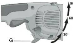
- Rotate handle into available 0°, 30°, 60°, or 90° position left OR right of center.
- Push in the handle release lever.
- Before turning the tool on, ensure that the handle is locked into a position and the handle release lever has returned to the original position flush with the tool housing.
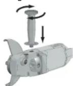
Rotating the Gear Case
Turn off and unplug tool before making any adjustments or removing or installing accessories. Before reconnecting the tool, depress and release the trigger switch to ensure that the tool is off.
- Remove the four corner screws attaching the gear case to motor housing.
- Without separating the gear case from motor housing, rotate the gear case head to desired position.
NOTE: If the gear case and motor housing become separated by more than 1/8", the tool must be serviced and re-assembled by a DEWALT service center. Failure to have the tool serviced may cause brush, motor and bearing failure.
- Re-install screws to attach the gear case to the motor housing. Tighten screws to 20 in./lbs. torque. Overtightening could cause screws to strip.
OPERATION
Power Source
Plug the large angle grinder into a dedicated electrical circuit. Operating this tool on a circuit with other tools will decrease tool performance.
Switch
CAUTION: Before connecting the tool to a power source or after a power failure, depress and release the trigger switch (A) once without depressing the lock-on button (B) to ensure that the switch is in the off position. If the trigger switch is locked on, the tool will start unexpectedly when power is reconnected to the tool. Hold the side handle and rear handle firmly to maintain control of tool at start up and during use.
TRIGGER OPERATION
To turn the tool on, depress the trigger switch (A). The tool will remain running while the trigger is depressed. Turn the tool off by releasing the trigger.
To turn tool on, depress trigger. Depress and hold lock-on button (B) while releasing trigger. Lock-on button will remain depressed and tool will remain on.
To turn the tool off, depress and release trigger. The lock pin button will pop out, permitting the trigger to disengage and causing the tool to turn off.
NOTE: Allow the tool to reach full speed before touching tool to work surface. Lift the tool from the work surface before turning the tool off.
⚠️CAUTION: Make sure the wheel has come to a complete stop before setting the tool down.
REMOVAL OF LOCK-ON FEATURE
The lock-on button can be permanently removed without compromising compliance with regulatory agencies shown on the tool's nameplate. Removal of the lock pin must be done by a DeWALT Service Center.
Mounting and Using Depressed Center Grinding Wheels and Sanding Flap Discs
MOUNTING AND REMOVING GUARD
Turn off and unplug tool before making any adjustments or removing or installing accessories. Before reconnecting the tool, depress and release the trigger switch to ensure that the tool is off.
IMPORTANT INFORMATION ABOUT GUARDS
Guards must be used with all grinding wheels, sanding flap discs, wire brushes and wire wheels. The tool may be used without a guard only when sanding with conventional sanding discs. DeWALT models D28493, D28494, D28474, D28499 are provided with a guard intended for use with depressed center wheels (Type 27), and hubbed grinding wheels (Type 27). The same guard is designed for use with sanding flap discs, wire brushes and wire wheels.
Grinding and cutting with wheels other than Type 27 and 29 require different accessory guards not included with the tool. Mounting instructions for these accessory guards are included in the accessory package.
CAUTION: When using a grinding wheel with a Type 27, 28, or 29 guard, be sure that the bottom surface of the grinding wheel is inside the the guard lip.
A CAUTION: DEWALT model D28497 Angle Sander may only be used for grinding by using appropriate accessory guard.
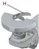
-
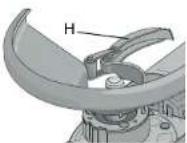
Open the guard latch (H), and align the lugs with slots on the gear case cover. Position the guard facing backward, as shown.
-
Push the guard down until the guard lugs engage and rotate freely in the groove on the gear case hub.
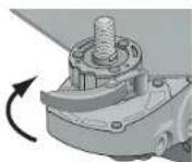
- With the guard latch open, rotate the guard into the desired working position that provides maximum protection to the user as shown.
- Close the guard latch to secure the guard on the gear case. You should be unable to rotate the guard by hand when the latch is closed. Do not operate the grinder with a loose guard or the clamp lever in open position.
- To remove the guard, follow the procedure above in reverse order.
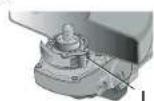
NOTE: The guard is pre-adjusted to the diameter of the gear case hub at the factory. If, after a period of time, the guard becomes loose, tighten the adjusting screw (I) with clamp in the closed position.
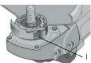
▲ CAUTION: Do not tighten the adjusting screw with the clamp lever in open position. Undetectable damage to the guard or the mounting hub may result.
MOUNTING AND REMOVING HUBBED WHEELS
Hubbed wheels install directly on the 5/8" — 11 threaded spindle.
1. Thread the wheel on the spindle by hand, seating the wheel against the soft mount.
2. Depress the spindle lock button and use a wrench to tighten the hub of the wheel.
- Reverse the above procedure to remove the wheel.
CAUTION: Failure to properly seat the wheel against the soft mount before turning the tool on may result in damage to the tool or the wheel.
MOUNTING NON-HUBBED WHEELS
Depressed center, Type 27 grinding wheels must be used with available accessory flanges. See the chart on pages 5–7 of this manual for more information.
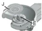
- Install the metal backing flange (J) on spindle (E) against the soft mount.
- Place wheel against the backing flange, centering the wheel on the backing flange pilot.
- While depressing the spindle lock button, thread the clamp nut (K) on spindle, piloting the raised hub on clamp nut in the center of grinding wheel.
- Tighten the clamp nut with a wrench.
- Reverse the above procedure to remove the wheel.
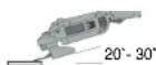
SURFACE GRINDING WITH GRINDING WHEELS
- Allow the tool to reach full speed before touching tool to work surface.
- Apply minimum pressure to work surface, to allow the tool to operate at high speed.
- Maintain a 20^ to 30^ angle between the tool and work surface.
- Continuously move the tool in a forward and back motion to avoid creating gouges in the work surface.
- Remove the tool from work surface before turning tool off. Allow the tool to stop rotating before setting it down.
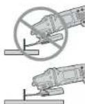
EDGE GRINDING WITH GRINDING WHEELS
CAUTION: Wheels used for cutting and edge grinding may break or kick back if they bend or twist while the tool is being used to do cut-off work or deep grinding. To reduce the risk of serious injury, limit the use of these wheels with a standard Type 27 guard to shallow cutting and notching (less than 1/2" in depth). The open side of the guard must be positioned away from the operator. For deeper cutting with a Type 1 wheel, use a closed, Type 1 guard. Type 1 guards are available at extra cost from your local dealer or authorized service center.
- Allow the tool to reach full speed before touching the tool to the work surface.
- Apply minimum pressure to work surface, to allow the tool to operate at high speed.
- Protect yourself during edge finishing by directing the open side of the guard away from you.
- Move the tool continuously in a forward and back motion to avoid creating gouges in the work surface.
- Remove tool from work surface before turning the tool off. Allow the tool to stop rotating before setting it down.
WARNING: Do not use edge grinding wheels for surface grinding applications because edge grinding wheels are not designed for side pressures encountered with surface grinding. Wheel breakage and injury may result.
SURFACE FINISHING WITH SANDING FLAP DISCS
- Allow the tool to reach full speed before touching tool to work surface.
- Apply minimum pressure to work surface, to allow the tool to operate at high speed.
- Maintain a 5^ to 10^ angle between the tool and work surface.
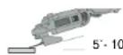
- Continuously move the tool in a forward and back motion to avoid creating gouges in the work surface.
- Remove the tool from work surface before turning tool off. Allow the tool to stop rotating before setting it down.
MOUNTING AND USING SANDING BACKING PADS
Sanding pads and sanding discs must be rated above minimum accessory speed as shown on tool. Recommended sanding backing pads and sanding discs are available at extra cost from DEWALT service centers and DEWALT dealers.
NOTE: Guard may be removed for sanding applications with backing pads and sanding discs. Sanding flap discs are considered grinding wheels by ANSI standards and require the use of a guard. (See Mounting and Using Depressed Center Grinding Wheels and Sanding Flap Discs).
MOUNTING SANDING BACKING PADS
Turn off and unplug tool before making any adjustments or removing or installing accessories. Before reconnecting the tool, depress and release the trigger switch to ensure that the tool is off.
CAUTION: Proper guard must be re-installed for grinding wheel, sanding flap disc, wire brush, or wire wheel applications after sanding applications are complete.
- Place or appropriately thread rubber backing pad (L) down to soft mount.
- Place the sanding disc (M) on the rubber backing pad (L).
- While depressing spindle lock, thread clamp nut (N) on spindle, piloting the
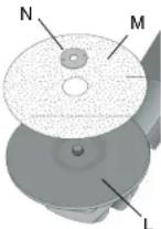
raised hub on the clamp nut into the center of sanding disc and backing pad.
- Tighten the clamp nut with the proper wrench.
- To remove the wheel, reverse the above procedure.
USING SANDING BACKING PADS
Choose the proper grit sandpaper for your application. Sandpaper is available in various grits. Coarse grits yield faster material removal rates and a rougher finish. Finer grits yield slower material removal and a smoother finish.
Begin with coarser grit discs for fast, rough material removal. Move to a medium grit paper and finish with a fine grit disc for optimal finish.
Coarse 16 - 30 grit
Medium 36 – 80 grit
Fine Finishing 100 - 120 grit
Very Fine Finishing 150 - 180 grit
- Allow the tool to reach full speed before touching tool to work surface.
- Apply minimum pressure to work surface, allowing tool to operate at high speed.
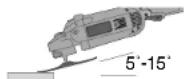
- Maintain a 5" to 15" angle between the tool and work surface. The sanding disc should contact approximately one inch of work surface.
- Move the tool constantly in a straight line to prevent burning and swirling of work surface. Allowing the tool to rest on the work surface without moving, or moving the tool in a circular motion causes burning and swirling marks on the work surface.
- Remove the tool from the work surface before turning the tool off. Allow the tool to stop rotating before setting it down.
Mounting and Using Wire Brushes and Wire Wheels
Turn off and unplug tool before making any adjustments or removing or installing accessories. Before reconnecting the tool, depress and release the trigger switch to ensure that the tool is off.
Wire brushes and wire wheels must be rated above minimum accessory speed as shown on tool. Use only wire brushes and wheels provided with a 5/8" – 11 threaded hub. A Type 27 guard is required when using wire brushes and wheels.
▲ CAUTION: Wear work gloves when handling wire brushes or wheels. Wire brushes and wheels can become sharp.
MOUNTING WIRE BRUSHES AND WIRE WHEELS
- Thread the wheel on the spindle by hand, seating the wheel against the soft mount.
- Depress the spindle lock button and use a wrench on the hub of the wire brush or wheel to tighten the wheel.
- To remove the wheel, depress the spindle lock button and use a wrench on the hub of the wire brush or wheel to loosen it.
NOTE: Failure to properly seat the wheel hub against the soft mount before turning the tool on may result in damage to the tool or wheel.
USING WIRE CUP BRUSHES AND WIRE WHEELS
Wire wheels and brushes can be used for removing rust, scale and paint, and for smoothing irregular surfaces.
- Allow tool to reach full speed before touching tool to work surface.
-
Apply minimum pressure to work surface, to allow the tool to operate at high speed.
-
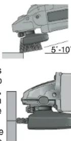
Maintain a 5° to 10° angle between the tool and work surface for wire cup brushes.
- Maintain contact between the edge of the wheel and the work surface with wire wheels.
- Continuously move the tool in a forward and back motion to avoid creating gouges in the work surface. Allowing the tool to rest on the work surface without moving, or moving the tool in a circular motion causes burning and swirling marks on the work surface.
- Remove the tool from the work surface before turning the tool off. Allow the tool to stop rotating before setting it down.
natural_image
Mechanical assembly diagram showing two views of a robotic arm with no visible text or symbolsMounting and Using Flaring Cup (Type 11) Wheel
MOUNTING FLARING CUP WHEEL GUARD
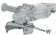
▲WARNING: The flaring cup wheel guard is not included with this tool. Flaring cup wheels require proper flanges and guards. 4" flaring cup wheel guard D284934 and 6" flaring cup wheel guard D284936 are available as accessories and include proper flange. Failure to use the proper flange and guard can result in injury resulting from wheel breakage and wheel contact.
Turn off and unplug tool before making any adjustments or removing or installing accessories. Before reconnecting the tool, depress and release the trigger switch to ensure that the tool is off.
- Install the guard as shown.
-
Guard body should be positioned between the spindle and the operator to provide maximum operator protection.
-
Securely tighten the two clamping screws (W) supplied with the guard.
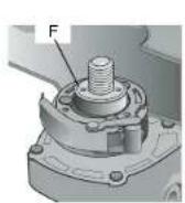
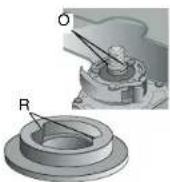
MOUNTING FLARING CUP WHEEL
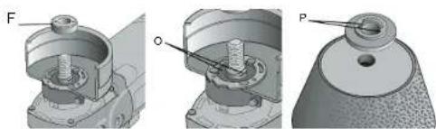
- Remove the soft mount (F).
- Install the flaring cup wheel backing flange, aligning the flats on spindle (O) with the flats on backing flange (F)
- Thread the flaring cup wheel on spindle by hand, seating wheel against backing flange.
- Depress the spindle lock button and tighten the wheel by hand.
- To remove the wheel, reverse the above procedure.
CAUTION: Failure to properly seat the wheel against backing flange before turning the tool on may result in damage to the tool or the wheel.
NOTE: Adjust the guard skirt so that only 1/8" of the wheel is exposed by loosening the bolts, allowing the guard to lengthen. Tighten the guard skirt bolts securely before using the grinder.
USING A FLARING CUP WHEEL
Flaring cup wheels are designed for heavy material removal.
- Allow the tool to reach full speed before touching tool to work surface.
- Apply minimum pressure to work surface, allowing the tool to operate at high speed.
natural_image
Technical illustration of mechanical components with labeled parts (F, O, P), no readable text or symbols present.- Maintain a 5^ to 10^ angle between the tool and the work surface.
- Continuously move the tool in a forward and back motion to avoid creating gouges in the w
- Remove the tool from work surface before turning tool off. Allow the tool to stop rotating before setting it down.
Mounting and Using Cutting (Type 1) Wheels
Cutting wheels include diamond wheels and abrasive discs. Abrasive cutting wheels for metal and concrete use are available. Diamond blades for concrete cutting can also be used.
WARNING: A closed, cutting wheel guard is not included with this tool. Cutting wheels require proper flanges and guards. A 7" cutting guard, D284931, is available as an accessory and includes proper, matching flanges. Failure to use proper flange and guard can result in injury resulting from wheel breakage and wheel contact.
MOUNTING CLOSED (TYPE 1) GUARD
Turn off and unplug tool before making any adjustments or removing or installing accessories. Before reconnecting the tool, depress and release the trigger switch to ensure that the tool is off.
- Open the guard latch (H), and align the lugs with slots on the gear case cover. Position the guard facing backward, as shown.
- Push the guard down until the guard lug engages and rotates freely in the groove on the gear case hub.
- Rotate guard (Q) into desired working position. The guard body should be posi-
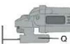
tioned between the spindle and the operator to provide maximum operator protection.
- Close the guard latch to secure the guard on the gear case cover. You should be unable to rotate the guard by hand when the latch is in closed position. Do not operate grinder with a loose guard or clamp lever in open position.
NOTE: The guard is pre-adjusted to the diameter of the gear case hub at the factory. If, after a period of time, the guard becomes loose, tighten the adjusting screw (I) with the clamp lever in the closed position.
CAUTION: Do not tighten adjusting screw with clamp lever in open position. Undetectable damage to guard or mounting hub may result.
MOUNTING CUTTING WHEELS
-
Remove Soft Mount (F).
-
Install wheel backing flange, aligning flats on spindle (O) with flats on backing flange (R).
- Place the wheel on the backing flange, centering the wheel on the backing flange pilot.
- Install the clamp nut, ensuring that the wheel remains centered on the backing flange.
- Depress the spindle lock button and tighten clamp nut with wrench.
- Reverse the above procedure to remove the wheel.
USING CUTTING WHEELS
WARNING: Do not use edge grinding/cutting wheels for surface grinding applications because these wheels are not designed for side pressures encountered with surface grinding. Wheel breakage and injury may result.
- Allow tool to reach full speed before touching tool to work surface.
- Apply minimum pressure to work surface, allowing tool to operate at high speed.
- Once you begin a cut, maintain the angle of the cutting wheel to the work surface. This will keep you from bending the wheel which could result in wheel breakage and injury.
- Remove the tool from work surface before turning tool off. Allow the tool to stop rotating before setting it down.
MAINTENANCE
Cleaning
▲WARNING: Blowing dust and grit out of the motor housing using clean, dry compressed air is a necessary regular maintenance procedure. Dust and grit containing metal particles often accumulate on interior surfaces and could create an electrical shock or electrocution if not frequently cleaned out. ALWAYS WEAR SAFETY GLASSES.
CAUTION: Never use solvents or other harsh chemicals for cleaning the non-metallic parts of the tool. Use a clean, dry rag only.
Lubrication
DeWALT tools are properly lubricated at the factory and are ready for use.
Repairs
To assure product SAFETY and RELIABILITY, repairs, maintenance and adjustment should be performed by authorized service centers or other qualified service personnel. Always use identical replacement parts.
Motor Brushes
When brushes become worn, the tool will automatically stop, preventing damage to the motor. Brush replacement should be performed by DeWALT authorized service centers or other qualified service personnel. Qualified service personnel should follow the procedures below when replacing motor brushes.
Turn off and unplug tool before making any adjustments or removing or installing accessories. Before reconnecting the tool, depress and release the trigger switch to ensure that the tool is off.
- Remove the brush doors located on the sides of motor housing.
- To remove the brush, hold the female terminal, which is attached to the brush lead wire, and disconnect the female terminal from the male terminal.
- Pull the brush straight up out of the brush holder.
- Replace brushes, in pairs, with original DEWALT brushes available from DEWALT authorized service centers.
- Ensure that the brushes slide freely in brush box.
- Reconnect the brush lead wire to brush box terminal.
- Re-install the brush doors before using the tool. Torque screws to 10 in./lbs., maximum. Overtightening may cause screws to strip.
Purchasing Accessories
Recommended accessories for use with your tool are available at extra cost from you local dealer or authorized service center. If you need assistance in locating any accessory for your tool, contact: DeWALT Industrial Tool Co., 701 East Joppa Road, Baltimore, MD 21286.
CAUTION: Accessories must be rated for at least the speed recommended on the tool warning label. Wheels and other accessories running over rated speed can fly apart and cause injury. Accessory ratings must always be above tool speed as shown on tool nameplate.
CAUTION: The use of any other accessory not recommended for use with this tool could be hazardous.
Three Year Limited Warranty
D=WALT will repair, without charge, any defects due to faulty materials or workmanship for three years from the date of purchase. This warranty does not cover part failure due to normal wear or tool abuse. For further detail of warranty coverage and warranty repair information, visit www.dewalt.com or call 1-800-4-D=WALT (1-800-433-9258). This warranty does not apply to accessories or damage caused where repairs have been made or attempted by others. This warranty gives you specific legal rights and you may have other rights which vary in certain states or provinces.
In addition to the warranty, DEWALT tools are covered by our:
1 YEAR FREE SERVICE
DEWALT will maintain the tool and replace worn parts caused by normal use, for free, any time during the first year after purchase.
90 DAY MONEY BACK GUARANTEE
If you are not completely satisfied with the performance of your
DEWALT Power Tool, Laser, or Nailer for any reason, you can return it within 90 days from the date of purchase with a receipt for a full refund – no questions asked.
FREE WARNING LABEL REPLACEMENT: If your warning labels become illegible or are missing, call 1-800-4-D€WALT for a free replacement. To request replacement labels, you will need to know the rated rpm of your tool. The rpm of your tool is stamped into the tool housing.
POUR TOUT RENSEIGNEMENT SUPPLÉMENTAIRE SUR CET OUTIL OU TOUT AUTRE OUTIL DEWALT, COMPOSER SANS FRAIS LE NUMÉRO:
1 800 4-DEWALT (1 800 433-9258)
CONSERVER CES DIRECTIVES!
MESURES DE SÉCURITÉ - GÉNÉRALITÉS
text_image
Technical diagram of a mechanical device with labeled parts A through G, showing exploded and assembled views.Composants
text_image
Technical diagram of a mechanical device with labeled parts A through G, showing exploded and assembled views.Características
INTERRUPTOR
natural_image
Mechanical assembly diagram showing two views (a and b) of a motor or gear assembly with labeled components (J, E, K), no readable text or symbols present.natural_image
Technical illustration of mechanical components including a bolt, housing, and a cap (no text or symbols present)natural_image
Mechanical assembly diagrams showing bolt, washer, and mounting components (no text or labels)Local D, Col. Obrera
MERIDA, YUC
Calle 63 #459-A - Col. Centro (999) 928 5038
MONTERREY, N.L
Av. Francisco I. Madero No.831 - Col. Centro (81) 8375 2313
PUEBLA, PUE
17 Norte #205 - Col. Centro (222) 246 3714
QUERETARO, QRO
Av. Madero 139 Pte. - Col. Centro (442) 214 1660
SAN LUIS POTOSI, SLP