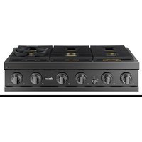
DTT36T960GM - Cooker Dacor - Free user manual and instructions
Find the device manual for free DTT36T960GM Dacor in PDF.


| Product type | Built-in gas range |
| Brand | Dacor |
| Model | DTT36T960GM |
| Width | 91.4 cm (36 inches) |
| Overall depth | Approximately 71 cm (28 inches) (estimated from installation dimensions) |
| Height with grates | Approximately 91 cm (36 inches) (adjustable) |
| Weight | Approximately 100 kg (estimated for a similarly sized model) |
| Power supply | 120 V, 60 Hz, AC, 20 A, dedicated grounded circuit |
| Gas supply | Natural gas (NG) or LPG (propane) – regulator included |
| Gas pressure (manifold) | NG: 13 cm WC (5 in WC); LPG: 25 cm WC (10 in WC) |
| Number of burners | 6 burners (including dual burners) |
| Burner type | Sealed burners with brass heads and porcelain or brass caps |
| Grates | 3 cast iron grates (specific position) |
| Controls | Knobs with electronic ignition |
| Main functions | Gas cooking, precise simmering, variable flame |
| Safety | Control lock (recommended), safety shut-off if flame goes out (not specified but likely) |
| Maintenance and cleaning | Regular cleaning of burners, grates and ventilation slots. Use non-abrasive products. |
| Spare parts / Repairability | Contact Dacor customer service – wiring diagram inside burner box |
| General information | Installation by a qualified professional. Warranty not covered for incorrect installation. |
Frequently Asked Questions - DTT36T960GM Dacor
User questions about DTT36T960GM Dacor
0 question about this device. Answer the ones you know or ask your own.
Ask a new question about this device
Download the instructions for your Cooker in PDF format for free! Find your manual DTT36T960GM - Dacor and take your electronic device back in hand. On this page are published all the documents necessary for the use of your device. DTT36T960GM by Dacor.
USER MANUAL DTT36T960GM Dacor
Installation Instructions
Rangetop
DTT48*960**/DTT36*960**

DG68-01476A-00
WARNING: If the information in these instructions is not followed exactly, a fire or explosion may result causing property damage, personal injury or death.
- Do not store or use gasoline or other flammable vapors and liquids in the vicinity of this or any other appliance.
• WHAT TO DO IF YOU SMELL GAS
- Do not try to light any appliance.
- Do not touch any electrical switch.
- Do not use any phone in your building.
- Immediately call your gas supplier from a neighbor's phone. Follow the gas supplier's instructions.
- If you cannot reach your gas supplier, call the fire department.
• Installation and service must be performed by a qualified installer, service agency or the gas supplier.
Contents
Before you Begin 3
Important Notes 3
Customer Service Information 4
Important Safety Instructions 5
Product specifications 11
What is in the Box 11
Parts and Tools Needed 12
Installation Requirements 13
In Preparation 13
Overall Rangetop Dimensions 14
Countertop Cutout Dimensions 15
Gas-Supply Requirements 19
Special Gas Requirements (gas models sold in Massachusetts) 19
Electrical Requirements 20
Installation Instructions 21
Installing the Rangetop 21
English2
Important Notes
natural_image
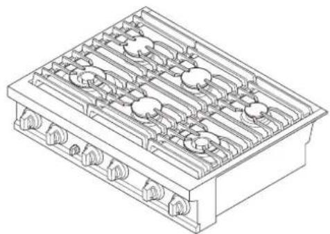
Isometric line drawing of a multi-tiered electrical or mechanical component with no visible text or symbolsOverall design/accessories may differ with the model.
Installer
- Read this manual thoroughly before installation.
- Leave this manual with the user.
• Write the rangetop's model/serial numbers in this manual for service/maintenance reference. - Remove all packaging from the rangetop before connecting it to the electric/gas supplies.
- Observe all governing regulations.
• Installation requires basic mechanical skills.
• The installer shall ensure proper installation. - Product failure due to improper installation is not warranted.
- Ensure the wall coverings around the rangetop can withstand the heat generated it.
• Overhead cabinetry should be at least 30 in. (76.2 cm) above the rangetop burners.
Service Technician
The electrical diagram is attached inside the burner box.
User
- Keep this manual for personal and professional reference.
- Ensure that qualified personnel install and ground the rangetop.
English 3
Customer Service Information
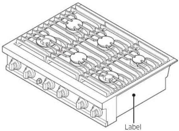
To resolve questions and installation issues, contact your Dacor dealer or the Dacor Customer Assurance Team. Before calling, have the rangetop's model/serial numbers available (see the data label, right-hand side of the rangetop chassis.)
natural_image
Technical line drawing of a multi-tiered industrial or electrical component with no visible text or symbolsDacor Customer Service
1-833-353-5483 (USA)
Monday - Friday 8:00 AM - 8:00 PM EST
1-844-509-4659 (Canada)
Monday - Friday 8:00 AM - 8:00 PM EST
English4
Important Safety Instructions
Read All Instructions Before Using This Appliance
- All electrical/gas equipment with moving parts can be dangerous. Read and follow this section carefully to minimize risk of property damage, personal injury, and death.
- Keep this manual in a handy place for personal and professional reference.
Symbols Used in This Manual
Follow these warning icons and symbols explicitly to prevent property damage and personal injury.

WARNING
Hazards or unsafe practices that may result in severe injury or death.

CAUTION
Hazards or unsafe practices that may result in electric shock, personal injury, or property damage.

NOTE
Useful tips and instructions.
California Proposition 65 Warning (US only)

WARNING
Cancer and Reproductive Harm - www.P65Warnings.ca.gov
Commonwealth of Massachusetts
This product must be installed by a licensed plumber or gas fitter qualified or licensed by the State of Massachusetts. When using ball-type gas shut-off valves, you must use the T-handle type. Multiple flexible gas lines must not be connected in series.
English 5
Important safety instructions
General Safety

WARNING
To reduce risk of property damage, fire, personal injury, and death:
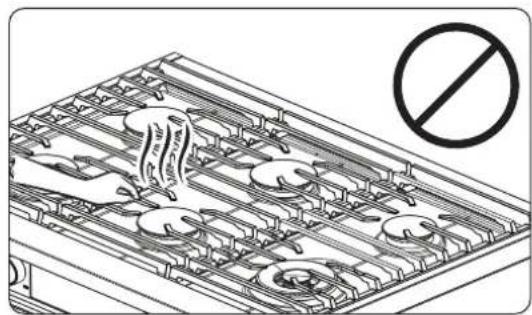
- Do not touch any part of the rangetop during or immediately after cooking.
- Learn where and how to shut off the rangetop's gas-intake valve.
- Do not let children near the rangetop or leave them unattended in the kitchen when the rangetop is in use. Dacor recommends activating the control lockout feature.
- Remove and immediately dispose of packaging. Do not let children play with the packaging.
- Do not keep objects of interest to children on or around the rangetop.
- Do not operate the rangetop if it is damaged, if it malfunctions, or if parts are missing.
- Use only dry pot holders.
- Do not heat sealed food containers on the rangetop.
- When disposing of the rangetop, cut off the power cord.
- Unplug the rangetop before service/maintenance.
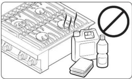
- Do not leave/store combustible material and liquids on/near the rangetop.
- Teach children not to touch or play with the controls or any part of the appliance.
- Ensure all meat and poultry is cooked thoroughly. Meat should always be cooked to an internal temperature of 160 °F (71 °C), and poultry to 180 °F (82 °C).
- Do not use the rangetop as a space heater.
- Air curtains or range hoods that blow air downward shall not be used with a gas range unless the hood and range are designed and tested according to the Standard for Domestic Gas Ranges, ANSI Z21.1 • CSA1.1, and listed by an independent testing laboratory for combination use.
English6
Fire Safety

WARNING
To reduce risk of property damage, fire, personal injury, and death:
natural_image
Illustration of a portable stove with steam rising, accompanied by a no-smoking bottle and stacked books (no text or symbols)- Keep flammable items away from the cooktop burners.
• Regularly clean the oven vents. - Do not use a towel or other bulky cloth as a pot holder.
- Do not douse a grease fire with water but turn off the burner, and if needed, use a multi-purpose, dry-chemical, or foam extinguisher.
- Do not heat sealed containers.
Gas Safety

WARNING
To reduce risk of property damage, fire, personal injury, and death:
If you smell gas:
- Close the valve and do not use the rangetop.
- Do not light a match, candle, or cigarette; or turn on any gas or electric appliances.
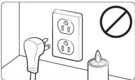
- Do not touch any electrical switches or plug in a power cord.
- Do not use any phone in your building, and evacuate the building.
- Immediately call your gas supplier from another building. Follow the supplier's directions.
- If you cannot reach your gas supplier, call the fire department.
Checking for Gas Leaks
Leak-testing the appliance must be done as the manufacturer directs. Do not use a flame to check for gas leaks. With a brush, spread a soap-and-water solution around the area in question. If there is a gas leak, small bubbles will appear in the solution.
English 7
Important safety instructions
Electrical and Grounding Safety

WARNING
To reduce risk of fire, electric shock, personal injury, and death:
natural_image
Pure electrical circuit lines without any symbols- Plug the appliance in to a grounded, 3-prong outlet.
- Do not remove the ground prong.
- Do not use an adapter or an extension cord.
- Do not use a damaged power plug/cord, or loose power outlet.
-
Do not modify the power plug, cord, or outlet.
-
Do not put a fuse in a neutral or ground circuit.
- Use a dedicated 120-volt, 60-Hz, 20-amp, AC, fused electrical circuit. A time-delay fuse or circuit breaker is recommended. Plug only the rangetop into this circuit.
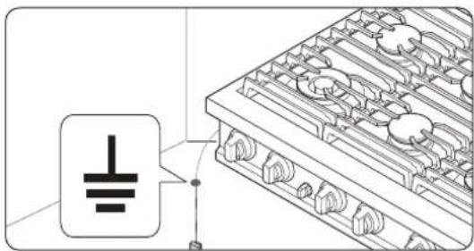
- Do not connect the ground wire to plastic plumbing, gas, or hot-water lines.
- The rangetop must be grounded. If it malfunctions, grounding provides a safe path for the current. The rangetop's grounding plug must be firmly plugged into an outlet that is properly installed and grounded per local regulations. If you are unsure your outlet is properly grounded, have it checked by a licensed electrician.
- If codes allow a separate ground wire, a qualified electrician should determine the proper path for this ground wire.
- Electrical service to the rangetop must conform to local codes, in the absence of which, it should meet the latest ANSI/NFPA No. 70 - Latest Revision (for the U.S.) or the Canadian Electrical Code CSA C22.1 - Latest Revisions.
- The rangetop owner shall ensure that proper electrical service is provided.
English8
Installation Safety
WARNING
To reduce risk of fire, electric shock, personal injury, and death:
- Only install the rangetop indoors away from weather, water, wind, and strong drafts.
- Select a location where a grounded, 3-prong outlet is easily accessible.
- If the rangetop is near a window, do not hang long curtains or paper blinds that may blow over/ onto the rangetop.
- For the rangetop to ventilate properly, its vents must not be blocked, and that there is enough clearance all around. The vents allow the necessary exhaust for the appliance to operate properly with correct combustion.
- Ensure the wall coverings near the appliance can withstand heat up to 200 °F (93 °C).
- Avoid cabinet storage above the rangetop. If such storage is unavoidable, leave at least 30 in. (76.2 cm) from cooking surface to cabinet bottom, or install a hood that projects at least 5 in. (12.7 cm) beyond the cabinet bottom.
Location Safety
WARNING
To reduce risk of property damage, fire, personal injury, and death:
natural_image
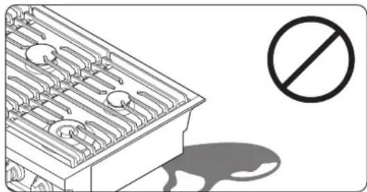
Illustration of a frying pan with no visible text or symbols- Do not install the rangetop outdoors or where it will be exposed to weather/water or wind/strong drafts.
- The rangetop must be installed within reach of a grounded, 3-prong outlet.
- Do not hang window treatments that could be blown onto the rangetop.
- For proper performance, the rangetop needs sufficient space all around the chassis.
- Wall coverings around the unit must withstand heat up to 194^ (90 °C).
- Cabinet storage above the rangetop is discouraged but if unavoidable, leave at least 30 in. (76.2 cm) between the cooking surface and cabinet bottoms.
English
Important safety instructions
Rangetop Safety

WARNING
To reduce risk of fire, electric shock, personal injury, and death:
natural_image
Diagram of an electronic device with a prohibition symbol (no text or labels present)- Turn all burners are off when not in use.
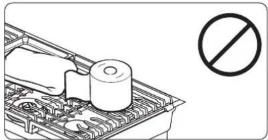
- Do not use aluminium foil to line the grates or any part of the rangetop.
- Do not leave burners unattended on medium or high heat settings.
-
Before igniting, ensure all burner caps are properly in place and all burners are level.
-
Always use the LITE ( ) position to ignite the burners, then ensure the burners ignite. If ignition fails, turn the knob to OFF, wait until the gas dissipates, then try again.
- When setting a burner to simmer, turn the knob slowly. Ensure the flame stays on.
- Place only cookware on the rangetop.
- Flame food only under an active ventilation hood.
- Turn off burners then immediately remove cookware from the burners.
• Before disassembling a burner, ensure all burners are off and the rangetop is completely cool.
• After cleaning the burner spreader, ensure it is completely dry before re-assembling.
• In assembling a burner, align the spark mark on the dual burner spreader with the electrode. - Do not pour water into the rangetop drip basin.
- Use cookware that is designed for rangetop cooking and is large enough to cover the burner grates. Adjust burner flames to remain under the cookware.
- To avoid cookware discoloration, deformity, and/or carbon monoxide poisoning, do not use cookware that is substantially larger than the grate.
- Turn cookware handles away from surface burners and the rangetop front edge.
- Stand back from the rangetop while frying.
- Heat frying oils slowly, and watch as they heat. If frying at high heat, closely watch the cooking process. If combining fats or oils when frying, mix them before heating.
• Use a deep-fryer thermometer if possible to monitor the oil temperature, and use minimal oil. - Do not fry frozen food or partially thawed food that it clumped with ice.
- Before moving fat-/oil-filled cookware, make sure it has completely cooled.
- To prevent delayed eruptive boiling, let hot liquids stand at least 20 seconds after turning off the burner so the liquid temperature can stabilize. In case of scalding, immerse the burn in cool water for at least 10 minutes, then cover with a clean, dry cloth. Do not apply cream/oil/lotion.
- Center pots on the grates. Do not put a pot larger than 9" in diameter on a rear burner. Oversized pots may impede airflow, making the flame sputter and burn inefficiently.
- Do not wear loose or hanging clothing when using the rangetop.
- Never leave plastic on the rangetop. Vented hot air can melt or ignite plastic or cause a buildup of dangerous pressure in closed plastic containers.
- Put only cookware on the rangetop.
- Thaw and pad food dry before frying. Moisture can cause oil to erupt and overflow.
• Always make sure the controls are OFF and the grates are cool before you remove them to prevent any possibility of being burned. - Keep combustible material away from the rangetop.
English10
Product specifications
What is in the Box
Common Parts

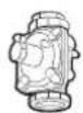
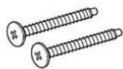
Manual Regulator (1) * Bolt (2)
36" DTT36*960
natural_image
Pure electrical circuit lines without any symbols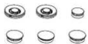
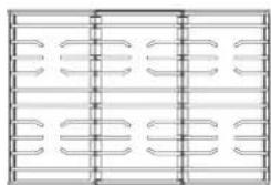
Cooktop burner grates (3) Burner heads(6) and Brass cap (8) Porcelain caps (8)
48" DTT48*960
natural_image
Pure electrical circuit lines without any symbols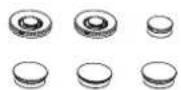
Cooktop burner grates (3) Burner heads(6) and Brass cap (8) Porcelain caps (8)
NOTE
- Verify that all supplied parts are present.
- If your rangetop was damaged during shipping or specified parts are missing, contact your local retailer. Do not install a damaged or incomplete rangetop.
- Porcelain and brass burner caps are provided to suit customer preference. (The brass will discolor with use; however, the discoloration does not affect the caps' intended function.)
- If you need an accessory marked with an asterisk (*), contact Dacor Customer Assurance via 833-353-5483(USA), 844-509-4659(Canada), or visit : www.dacor.com
English
Product specifications
Parts and Tools Needed
Parts Needed
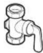
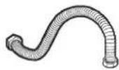


Gas line shut-off valve Flexible metal appliance connector 12 in (ID) x 5 ft
Flare union adapter 34 in (NPT) x 12 in (ID)
Flare union adapter 12 in (NPT) x 12 in (ID)
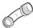
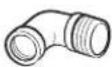
135-degree elbow (option) 90-degree elbow (option)
Tools Needed
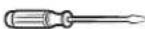
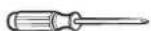
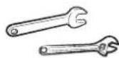
Flat-blade screwdriver Phillips screwdriver Open-end or adjustable wrench
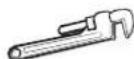
Pipe wrench (2)
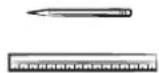


14 " Nut driver Pencil, ruler Level Pipe-joint compound
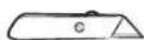
Utility knife Soap-water solution Pliers Saber saw
English12
Installation Requirements
In Preparation
- Before cutting the opening in the countertop, verify that there will be no conflict between the rangetop chassis and anything in the cabinet below.
- Remove all packing material and accessories from the rangetop, and verify that all items are present before beginning the installation.
Location Requirements
Before you begin the installation, review this section thoroughly. These dimensions must be met for safe operation. Location of the electrical outlet and gas piping may be adjusted to meet the specified parameters.

CAUTION
The rangetop complies with the maximum allowable wood-cabinet temperature of 194 °F (90 °C). Ensure the wall covering, countertops, and surrounding cabinets can withstand this temperature to avoid discoloration, delamination, or melting.
Maintain These Minimum Clearances
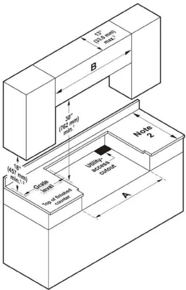
- Vertical to combustible surface from rangetop grate level; if installing a ventilation hood, check hood spec's for minimum required clearances.
- See Cabinet/Countertop Dimensions -Top View.
- This specification is not applicable for cabinets more than a horizontal distance of 10" (25.4 cm) from the edge of the rangetop.
| Rangetop DTT36*960 DTT48*960 | |
| A 36" (91.44 cm) 48" (121.9 cm) | |
| B | 36" (91.44 cm)*42" (106.7 cm)** 48" (121.9 cm)*54" (137.2 cm)** |
* Minimum
** Recommended
A: Rangetop cutout
B: Range hood cutout
English
Installation Requirements
Overall Rangetop Dimensions
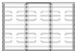
DTT36*960

DTT48*960
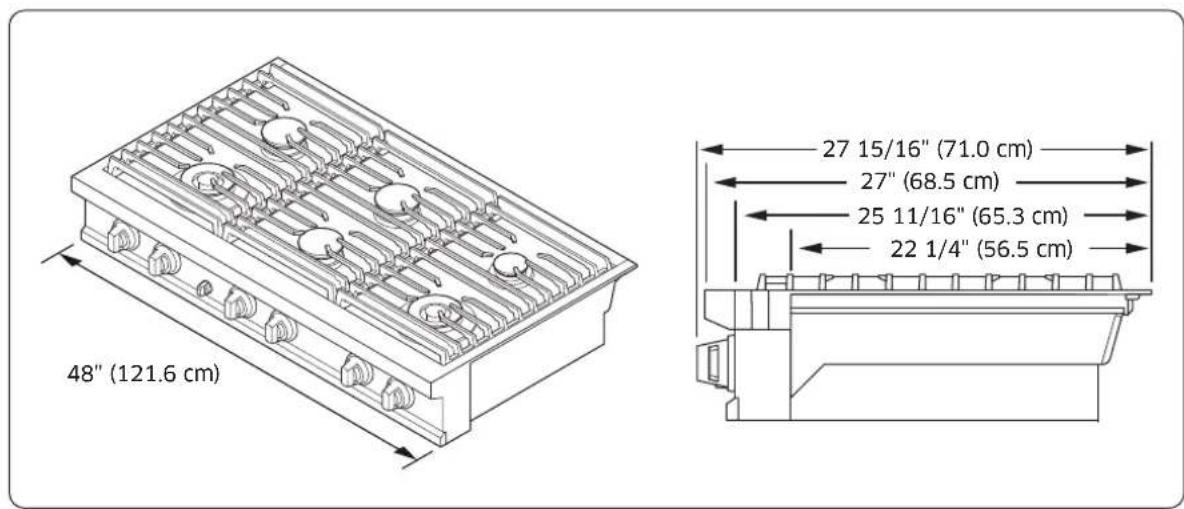
English14
Countertop Cutout Dimensions
Cabinet/Countertop Dimensions (front view)
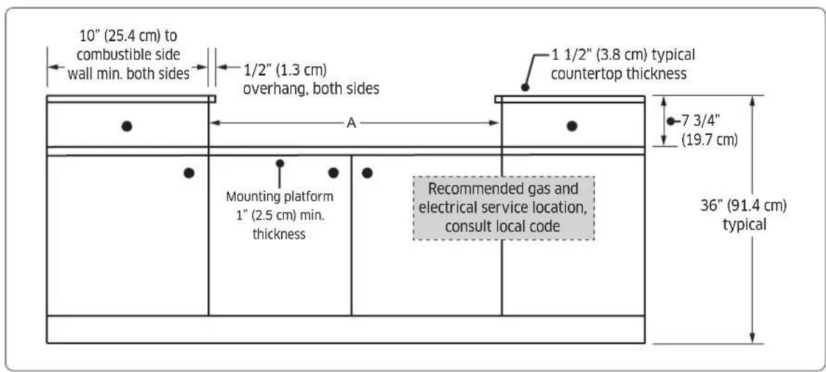
Installed Rangetop (side view)
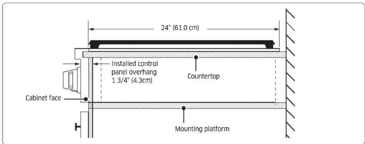

CAUTION
Cutout dimensions must be observed. Any overage could create severe problems.

NOTE
Cabinet tolerances +1/16" (+1.6 mm) -0 unless otherwise noted.
English
Installation Requirements
Installed Rangetop (side view)
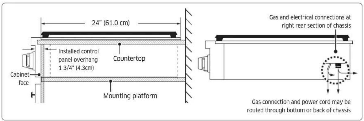
Cabinet/Countertop Cutout Dimensions-No Downdraft Vent (top view)
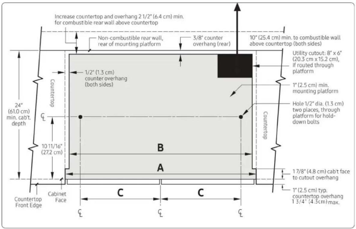
| Rangetop Model A B C | |||
| DTT36*960 36" (91.4 cm) 35" (88.9 cm) 16 5/8" (42.2 cm) | |||
| DTT48*960 48" (121.9 cm) 47" (119.4 cm) 20 13/16" (52.9 cm) |
English16
Cabinet/Countertop Cutout Dimensions-With Downdraft Vent (top view)

NOTE
Gas and electrical connections must be routed through the bottom of the rangetop when installed with a downdraft vent.
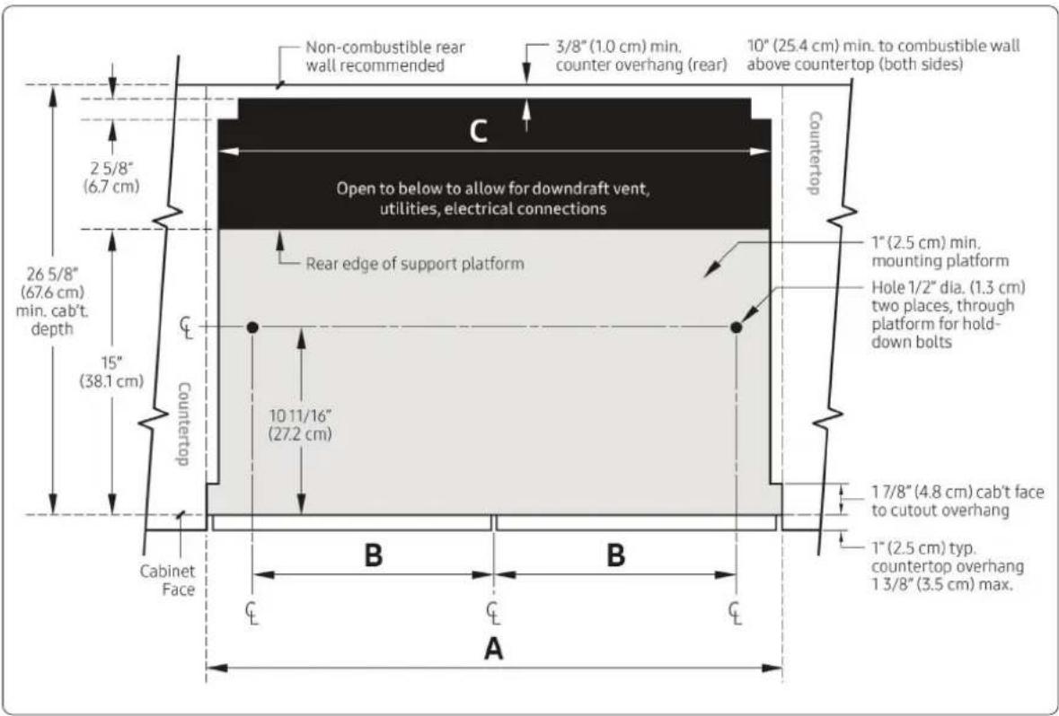
| Model A: Cutout Width B: Hole Offset | C: Downdraft Vent Cutout | Approved Downdraft Vent Models* | ||
| DTT36*960 | 36" (91.4 cm) | 16 5/8" (42.2 cm) | 33 1/2" (85.1 cm) | MRV3615M/S |
| DTT48*960 | 48" (121.9 cm) | 20 13/16" (52.9 cm) | 43 1/2" (110.5 cm) | MRV48M/S |
* IMPORTANT: Use only the downdraft vent models specified.
English
Installation Requirements
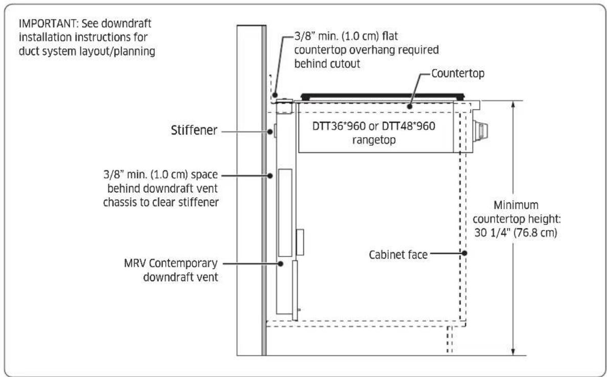
Cabinet/Countertop-With Downdraft Vent (side view)
Utility Locations and Dimensions (rear)
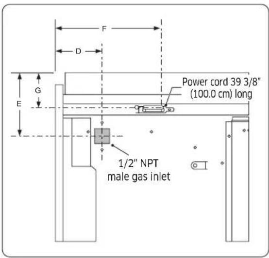
| Dimension DTT36*960 DTT48*960 | ||
| D 3 1/2" (8.9 cm) 4" (10.1 cm) | ||
| E 4 11/16 (11.9 cm) 4 11/16 (11.9 cm) | ||
| F 5 1/8" (13 cm) 19 3/4" (50.1cm) | ||
| G 2 11/16" (6.9 cm) 2 11/16' (6.9 cm) |
English18-
Gas-Supply Requirements
Provide Adequate Gas Supply
The rangetop operates at a manifold pressure of:
- 5 in. (13 cm) of water column for natural gas/natural-gas-at-high-altitude (NG-H) or
- 10 in. (25 cm) of water column for LP gas (propane)/LP-gas-at-high-altitude (LP/H).
Ensure your rangetop receives the proper gas. When verifying regulator function, the inlet pressure must be at least 1 in. (2.5 cm) greater than the given operating (manifold) pressure.
The pressure regulator (at the inlet of the rangetop manifold) must stay in the supply line no matter the type of gas used.

NOTE
- Use only the provided regulator, which must be installed in the gas line that runs from the gas inlet to the shut-off valve.
- An external, manual shut-off valve must be installed between the gas inlet and rangetop for turning on/off gas to the appliance.
- Have a qualified technician install the connectors.
- For a new rangetop, never install used connectors, which can leak gas and cause personal injury. Use only new, flexible connectors.
Special Gas Requirements (gas models sold in Massachusetts)
Commonwealth of Massachusetts Requirements

WARNING
• Gas leaks may occur in your system, creating a dangerous condition.
- Gas leaks cannot always be detected by smell alone.
Gas suppliers recommend installing a UL-approved gas detector per manufacturer specifications.
- The rangetop must be installed by a Massachusetts-certified plumber or gas fitter.
- A T-handle manual gas valve MUST be installed in the gas-supply line to the rangetop.
- If a flexible gas connector is used, it must be a single length of line.
English
Electrical Requirements

WARNING
-
The owner shall verify that the electrical service meets electrical requirements and that the outlet is properly installed by a licensed electrician.
• To reduce risk of fire, electric shock, or personal injury: -
Do not use an extension cord or adapter plug with the rangetop.
- The rangetop must be properly grounded.
-
Do not use a damaged power plug or loose wall outlet.
-
Do not modify, remove, or otherwise defeat the plug's grounding (3rd) prong. If you have a 2-prong outlet, or you suspect the outlet is not properly grounded, have a qualified electrician check the circuit and outlet; install the proper outlet if needed.
- All wiring and grounding must comply with local codes or, in their absence, the National Electrical Code, ANSI/NFPA No. 70 - Latest Revision (US), or the Canadian Electrical Code CSA C22.1 - Latest Revisions and local codes.
-
The wiring diagram is inside the burner box.
-
All gas models are equipped with a power cord with an equipment-grounding conductor and a grounding plug.
- All gas models in the US and Canada require a 120 V, 60-Hz, AC, approved electrical service with 20-amp circuit breaker or time-delay fuse.
- NEVER connect ground wire to plastic plumbing lines, gas lines, or water pipes.

NOTE
Re-ignition may malfunction if the voltage between Neutral and Ground is over 20 VAC. Make sure the voltage is under 20 VAC.

CAUTION
Failure to follow these instructions can cause fire, electrical shock, death.
Additional installation requirements for mobile homes:
Installation of appliances designed for mobile-home use must comply with the Manufactured Home Construction and Safety Standard, Title 24 CFR, Part 3280 (formerly the Federal Standard for Mobile-Home Construction and Safety, Title 24, HUD, Part 280) or, when the standard does not apply, the Standard for Manufactured-Home Installations, latest edition (Manufactured-Home Sites, Communities and Selups), ANSI A225.1, latest edition, or with local codes. In Canada, mobile-home installation must comply with the current CAN/CSA Z240/MH Mobile-Home Installation Code.
English20
Installing the Rangetop
IMPORTANT
Carefully read these instructions and the Important Safety Instructions (Pg. 5) before installing/ operating the rangetop. Improper installation, adjustment, service, or maintenance can lead to personal injury and property damage. Product failure due to improper installation is not warranted.

NOTE
Only qualified personnel should install the rangetop.
Unpacking the Rangetop
- Remove all packaging. (Failure to do so could damage the rangetop.)
- Cross-check all loose parts against the parts list. (See Pg. 12.)
- Report shipping damage and missing parts to your retailer. Do not install a damaged or incomplete rangetop.
Installing the Rangetop
- Install any downdraft vent first, per manufacturer instructions.
- Slide the rangetop into the cutout, and secure it to the support platform with the provided anchor bolts.
Connecting the Gas Supply
- Shut off the main gas-supply valve before disconnecting the old rangetop.
- Complete the gas hookup.
- Open the gas valve, and relight the burners on any other gas appliances.

NOTE
Because hard piping restricts movement of the appliance, use a CSA International-certified flexible metal appliance connector unless local codes require hard piping.

WARNING
Follow the information in this manual exactly to avoid a fire or explosion.
- Do not store or use gasoline or other flammable liquids near the rangetop.
• IF YOU SMELL GAS:
- DO NOT light a match, lighter, or any ignition device.
- DO NOT light any appliance.
- DO NOT touch any electrical switch.
- Evacuate the building.
- DO NOT use any phone in your building; from a neighbor's phone, immediately call your gas supplier, and follow their directions. (Otherwise, call the fire department.)
• Installation and service must be done by a qualified installer, service agency, or gas supplier.
• Install only the included gas regulator. (Ensure the regulator's arrow points to the appliance.) - Do not overtighten gas connections and fittings.
• Before use, test the gas lines for leaks. (See Pg. 22.)
English
Installation Instructions
Connecting the Gas Supply, cont.
Never install an old connector on a new appliance. For hard piping, carefully align the pipe; the rangetop can-not be moved after the connection is made.
To prevent gas leaks, apply pipe-joint compound or wrap pipe-thread tape with Teflon on all male (external) pipe threads.
- Attach the provided gas-pressure regulator to the rangetop pipe nipple inlet. (For tight installations, the regulator may be installed upstream from the nipple, anywhere between the shut-off valve and the rangetop. For best performance, minimize gas-pressure loss by attaching the regulator as close as possible to the gas inlet.
- Complete the connection by installing a flexible gas line between the pressure regulator and the shut-off valve.
Flexible Connector Hookup
Installer: Inform the consumer of the location of the gas shut-off valve.
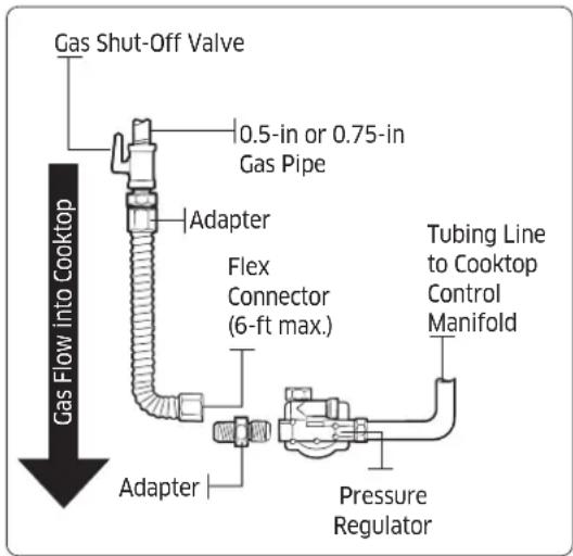

NOTE
The gas shut-off valve should be installed on the gas piping, away from the rangetop, easily accessible for quick opening/closing.
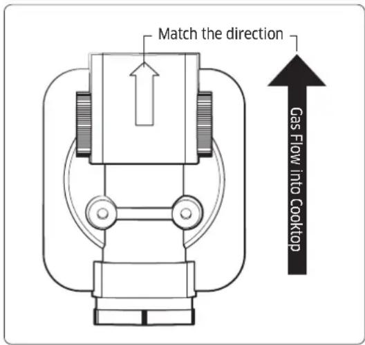

NOTE
When connecting the pressure regulator, pay attention to the direction of the pressure regulator. (If it is connected in reverse, the pressure regulator may shut off the gas.)
English22
Checking for Gas Leaks

WARNING
To prevent an explosion/fire hazard possibly leading to personal injury or death, DO NOT use a flame to check for gas leaks. When using pressures above 1/2 psig to test the home gas-supply system, disconnect the rangetop and individual shut-off valve from the supply line. When testing with pressures of 1/2 psig or less, isolate the rangetop by closing the individual shut-off valve.
- When all connections are made, ensure all rangetop controls are OFF, and turn on the main gas-supply valve.
- Use a liquid leak detector at all joints.
- Tighten connections as needed to prevent gas leakage in the rangetop or supply line.
Making the Electrical Connections

WARNING
- Disconnect power at the main circuit breaker or fuse box before making electrical connections.
- BEFORE operating/testing, follow the grounding requirements (pg. 20) of this manual. Improper connection of the grounding plug is an electric-shock risk.
-
The electrical system (including power cord) is factory-installed/-wired. Altering any part of this system may cause a short or overload.
-
Plug in the power cord. (Ensure the outlet meets all applicable electrical codes; See Pg. 20.)
-
After installing the rangetop, check the gas-supply line to verify it was not damaged and remains connected.
Assembling the Rangetop Burners

CAUTION
- Do not operate the rangetop burners without all burner parts in place.
• To avoid electric shock, do not:
- push in any burner controls while removing the burner.
- remove the top or touch the electrode of any burner while another burner is on.
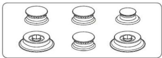
natural_image
Six identical mechanical component diagrams arranged in two rows, each with a central circular feature (no text or symbols)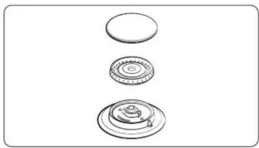
natural_image
Three technical line drawings of mechanical components, no text or symbols present-
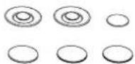
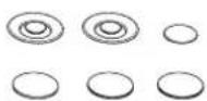
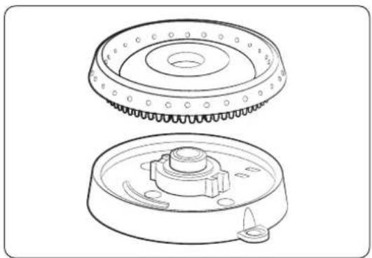
Place the burner heads on their bases (see left). The electrodes fit in the slot in the bottom of the heads, which should lie flat.
-
Place the caps on their respective burner heads.
Installation Instructions
Dual Burner Heads/Caps
Round Burner Head/Caps
natural_image
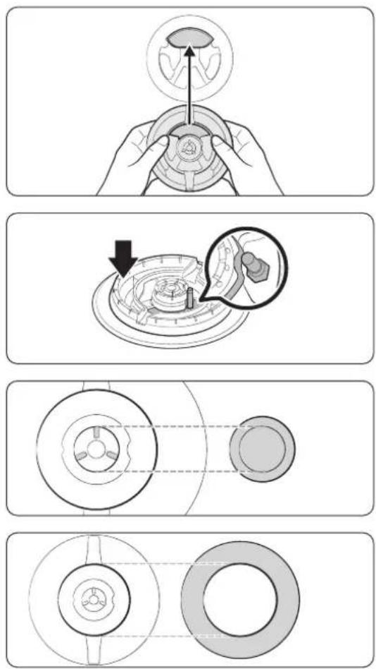
Technical line drawing of two mechanical components with no visible text or symbols- Orient the burner head so the opening for the electrode aligns with the electrode.
- Install the burner head so the electrode passes through its opening in the head. Ensure the burner head lies flat on the stove top.
-
Size the burner caps to the burners, then install the caps on the heads.
-
Put the burner heads on the burner bases. The bottom of the head fits within the burner base.
- Twist the head until it drops into place. Twist the head back and forth to verify it is properly seated.
- Put the burner caps (brass or porcelain) on the burner heads. The ridge around the bottom edge of the cap fits around the top of the burner head.
CAUTION
Burner heads and caps must rest flat on the heads.
English24
Verifying Burner Function
After the cooktop is fully installed and plugged in, make sure all burners work properly.
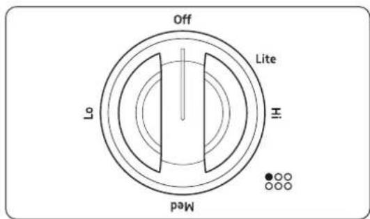
-
Push-turn a burner knob to the Lite. (A "clicking" sound means the electronic ignition system is functional. The burner ignites about 4 seconds later, after air is purged from the line.)
-
After ignition, turn the knob to a setting.(The "clicking" stops; flame height lowers as you turn the knob counterclockwise.)
-
Perform this procedure for each burner.
Installation Instructions
Checking Flame Quality
All burner flames must be visually checked to assess their quality.

CAUTION
If you want measure the flame, take care to avoid burn injuries.
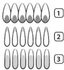
- Soft blue flames—Normal for natural gas.
- Yellow tips on outer cones-Normal for LP gas.
- Yellow flames—Abnormal for any gas operation.

NOTE
If the burner flame looks like Ex. 3, call for service, and do not use the rangetop. Ex. 1 or 2 are normal burner flames.
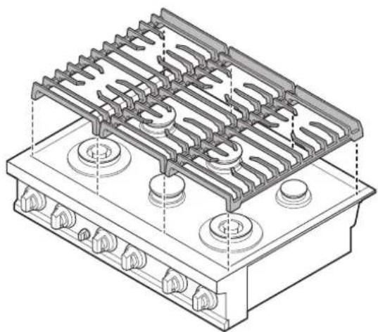
Installing the Grates

NOTE
For best results and longest life, install the grates as instructed. The grates occupy specific positions on the rangetop and should only be used in those positions. (To help with installation, each grate's position is formed into the bottom of the grate.)
The back of the right-hand grate is notched to help with placement. When installed properly, the openings in the grates are centered over the burners.
To correctly position the grates:
- Find the notch on the back of the right-hand grate, and carefully lower it until its legs rest in the corresponding dimples on the rangetop.
- Likewise place the remaining grates so their feet rest in the corresponding dimples.
natural_image
Isometric technical drawing of a gas stove with cooling fins and mounting holes (no text or labels)English26
Final Installation Checklist
After installing the rangetop, ensure all control knobs are OFF. Review this checklist to confirm the rangetop is properly installed and ready to operate.
- The gas line was properly connected to the rangetop.
• The gas was turned on. - All connections were checked for leaks.
- The rangetop is properly plugged in to a grounded electrical outlet.
- The rangetop burners and grates are properly assembled.
- All burners were tested and function properly.

NOTE
The owner is responsible for having the rangetop properly installed.
dacor
natural_image
Isometric line drawing of a multi-tiered electrical or mechanical component with no visible text or symbolsnatural_image
Illustration of a portable stove with steam rising, accompanied by a bottle and a stack of books, no text or symbols present.natural_image
Illustration of an electrical outlet with a light bulb and a candle, no text or symbols presentnatural_image
Pure electrical circuit lines without any symbolsnatural_image
Illustration of a portable stove with cooling fans and a prohibition symbol (no text or labels)natural_image
Diagram of a device with a circular symbol and no text or labels present, showing internal components without any readable text or symbols.natural_image
Pure electrical circuit lines without any symbolsnatural_image
Pure electrical circuit lines without any symbolsEspañol 15
natural_image
Six identical mechanical component diagrams arranged in two rows, each with a central circular feature (no text or symbols)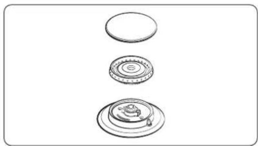
natural_image
Three technical line drawings of circular components with no text or symbolsnatural_image
Technical line drawing of a mechanical component with two views: top shows a flanged circular component, bottom shows a central gear-like structure with mounting holes (no text or symbols)natural_image
Isometric technical drawing of a gas stove or heating unit with cooling fins and mounting holes (no text or symbols)Español28
natural_image
Isometric line drawing of a multi-tiered electrical or mechanical component with no visible text or symbolsService client Dacor
natural_image
Illustration of a portable stove with steam rising, accompanied by a no-smoking bottle and stack of books (no text or symbols)natural_image
Illustration of an electrical outlet with a bulb and a candle, no text or symbols presentnatural_image
Pure electrical circuit lines without any symbolsnatural_image
Illustration of a portable stove with cooling fans and a prohibition symbol (no text or labels)natural_image
Diagram of a device with a cylindrical component and a prohibition symbol (no text or labels)natural_image
Pure electrical circuit lines without any symbolsnatural_image
Pure electrical circuit lines without any symbolsnatural_image
Six identical mechanical component diagrams arranged in two rows, each with a central bore and concentric rings (no text or symbols)natural_image
Three technical line drawings of circular components with no text or symbolsFrançais24
natural_image
Technical line drawing of two mechanical components with no visible text or symbolsnatural_image
Technical line drawing of a gas stove with cooling fins and mounting holes (no text or symbols)Français
- Installation Instructions
- Rangetop
- Contents
- Before you Begin 3
- Customer Service Information 4
- Important Safety Instructions 5
- Product specifications 11
- Installation Requirements 13
- Installation Instructions 21
- Important Notes
- Installer
- Service Technician
- User
- Customer Service Information
- Dacor Customer Service
- Important Safety Instructions
- Read All Instructions Before Using This Appliance
- Symbols Used in This Manual
- WARNING
- CAUTION
- NOTE
- California Proposition 65 Warning (US only)
- Commonwealth of Massachusetts
- General Safety
- Fire Safety
- Gas Safety
- If you smell gas:
- Checking for Gas Leaks
- Electrical and Grounding Safety
- Installation Safety
- Location Safety
- Rangetop Safety
- English10
- Product specifications
- What is in the Box
- Parts and Tools Needed
- Parts Needed
- Tools Needed
- Installation Requirements
- In Preparation
- Location Requirements
- Overall Rangetop Dimensions
- Countertop Cutout Dimensions
- Gas-Supply Requirements
- Provide Adequate Gas Supply
- Special Gas Requirements (gas models sold in Massachusetts)
- Commonwealth of Massachusetts Requirements
- Electrical Requirements
- Additional installation requirements for mobile homes:
- Installing the Rangetop
- IMPORTANT
- Unpacking the Rangetop
- Connecting the Gas Supply
- Connecting the Gas Supply, cont.
- Flexible Connector Hookup
- Making the Electrical Connections
- Assembling the Rangetop Burners
- Verifying Burner Function
- Checking Flame Quality
- Installing the Grates
- Final Installation Checklist
- dacor
- Service client Dacor
- Français24
Brand : Dacor
Model : DTT36T960GM
Category : Cooker