
iGen5000cv - Generator WESTINGHOUSE - Free user manual and instructions
Find the device manual for free iGen5000cv WESTINGHOUSE in PDF.

| Product type | Digital Inverter Generator |
| Brand | Westinghouse |
| Model | iGen5000cv |
| Continuous Power (Gasoline) | 3700 W |
| Peak Power (Gasoline) | 4500 W |
| Rated Voltage | 120 V |
| Rated Frequency | 60 Hz |
| Phase | Single Phase |
| Total Harmonic Distortion | ≤ 3% |
| Engine Displacement | 224 cc |
| Start Type | Recoil |
| Fuel Tank Capacity | 12.8 L (3.4 US gal) |
| Fuel Type | Unleaded gasoline 87-93 octane (max 10% ethanol) |
| Engine Oil Capacity | 0.60 L (0.63 US qt) |
| Recommended Oil Type | SAE 10W-30 |
| Spark Plug | F7RTC (gap 0.60-0.80 mm) |
| Grounding System | Floating Neutral |
| Voltage Regulator | Digital |
| Alternator Type | Permanent Magnet |
| Maximum Ambient Temperature | 40°C (104°F) |
| Certifications | EPA, CARB |
| Special Features | CO Sensor, Eco Mode, Digital Data Center, Parallel Operation |
| Outlets | 1x NEMA TT-30R (120V, 30A), 1x NEMA 5-20R duplex (120V, 20A), 2x USB ports (5V, 2.1A) |
| Protection | Main circuit breaker, individual circuit breakers, low oil shutdown, overload shutdown |
Frequently Asked Questions - iGen5000cv WESTINGHOUSE
User questions about iGen5000cv WESTINGHOUSE
0 question about this device. Answer the ones you know or ask your own.
Ask a new question about this device
Download the instructions for your Generator in PDF format for free! Find your manual iGen5000cv - WESTINGHOUSE and take your electronic device back in hand. On this page are published all the documents necessary for the use of your device. iGen5000cv by WESTINGHOUSE.
USER MANUAL iGen5000cv WESTINGHOUSE
iGen4500cv
Digital Inverter Generator
Gasoline: 3700 Running Watts | 4500 Peak Watts
DO NOT RETURN THIS PRODUCT TO THE STORE
If you have questions or need assistance, please call customer service at 855-944-3571.
INTRODUCTION
TABLE OF CONTENTS
INTRODUCTION
DISCLAIMERS....2
ALL RIGHTS RESERVED....2
SPECIFICATIONS
SPECIFICATIONS....3
SAFETY
SAFETY DEFINITIONS....4
SAFETY SYMBOLS....4
SAFETY INSTRUCTIONS ....5
SAFETY LABELS AND DECALS....7
CO SENSOR....8
ACTION LABEL......8
CONTROL PANEL CO AUTO-SHUTOFF 8
COMPONENTS
GENERATOR COMPONENTS....9
DIGITAL DATA CENTER....9
ASSEMBLY
CARTON CONTENTS 11
INITIAL OIL FILL 11
FUEL....12
OPERATION
GENERATOR LOCATION....13
GROUNDING....13
BREAK-IN PERIOD 14
BEFORE STARTING THE GENERATOR....14
STARTING THE ENGINE 14
FREQUENCY OF USE 14
ECO MODE....15
⚠ WARNING: Operating, servicing, and maintaining this equipment can expose you to chemicals including engine exhaust, carbon monoxide, phthalates, and lead, which are known to the State of California to cause cancer and birth defects or other reproductive harm. To minimize exposure, avoid breathing exhaust, and wear gloves or wash your hands frequently when servicing this equipment. For more information go to www.P65warnings.ca.gov.
DISCLAIMERS
All information, illustrations, and specifications in this manual were in effect at the time of publishing. The illustrations used in this manual are intended as representative reference views only. We reserve the right to make any specification or design change without notice.
AC CIRCUIT BREAKERS....15
OVERLOAD RESET 15
POWER MANAGEMENT....16
EXTENSION CORDS 16
PARALLEL OPERATION....17
TRANSPORTING....18
MAINTENANCE
MAINTENANCE SCHEDULE 19
MAINTENANCE REPLACEMENT PARTS ....19
AIR FILTER MAINTENANCE....19
ENGINE OIL LEVEL CHECK....20
ENGINE OIL CHANGE....21
SPARK PLUG MAINTENANCE 21
SPARK ARRESTOR SERVICE....22
STORAGE....22
VALVE CLEARANCE 23
TROUBLESHOOTING
TROUBLESHOOTING....24
EXPLODED VIEWS AND PARTS LISTS
ENGINE EXPLODED VIEW....25
ENGINE PARTS LIST 26
ENGINE PARTS LIST CONTINUED....27
GENERATOR EXPLODED VIEW 28
GENERATOR PARTS LIST....29
SCHEMATICS
SCHEMATICS....31
ESPAÑOL....32
FRANÇAIS......56
ALL RIGHTS RESERVED
All rights reserved. No reproduction allowed in any form without written permission from Westinghouse Outdoor Power Equipment, LLC.
DANGER

Read this manual before using or performing maintenance on this product. Failure to follow the instructions and safety precautions in this manual can result in serious injury or death.
SAVE THESE INSTRUCTIONS
SPECIFICATIONS
SPECIFICATIONS
| Running Watts: | 3700 Gas |
| Peak Watts: | 4500 Gas |
| Rated Power @1.0 Power Factor: | 3.7 kW Gasoline |
| Peak Power: | 4.5 kVA Gasoline |
| Rated Voltage: | 120V |
| Rated frequency: | 60 Hz @ 3600 RPM |
| Phase: | Single phase |
| Total Harmonic Distortion: | ≤ 3% |
| Engine Displacement: | 224 cc |
| Starting Type: | Recoil |
| Fuel Capacity: | 3.4 Gal (12.8 L) |
| Fuel Type: | 87–93 octane* |
| Oil Capacity: | 0.63 US qt (0.60 L) |
| Oil Type: | SAE10W30 |
| Spark Plug: | F7RTC |
| Spark Plug Gap: | 0.024 – 0.032 in.(0.60 – 0.80 mm) |
| Valve Intake Clearance: | 0.0031 – 0.0047 in(0.08 – 0.12 mm) |
| Valve Exhaust Clearance: | 0.0051 – 0.0067 in(0.13 – 0.17 mm) |
| AC Grounding System: | Floating neutral |
| Voltage Regulator: | Digital |
| Alternator Type: | Permanent magnet |
| Maximum Ambient Temperature: | 104°F (40°C) |
| Certifications: | · EPA· CARB |
*Ethanol content of 10% or less. DO NOT use E15 or E85.
NOTICE
This product is designed and rated for continuous operation at ambient temperatures up to 104^ F ( 40^ C). If needed, this product can be operated at temperatures ranging from 5^ F ( 15^ C)– 122^ F ( 50^ C) for short periods. If the product is exposed to temperatures outside of this range during storage, it should be brought back within this range before operation. This product must always be operated outdoors in a well-ventilated area and away from doors, windows, and other vents.
Maximum wattage and current are subject to and limited by such factors as fuel BTU content, ambient temperature, altitude, engine conditions, etc. Maximum power decreases about 3.5% for each 1,000 feet above sea level, and will also decrease about 1% for each 10°F (6°C) above 60°F (16°C) ambient temperature.
PRODUCT REGISTRATION
For trouble-free warranty coverage, it is important to register your Westinghouse generator.
You can register by:
- Completing and mailing the product registration card included in the carton.
- Registering your product online at: https://westinghouseoutdoorpower.com/pages/warranty-registration
- Scan the following QR code with your smartphone camera to be directed to the mobile registration link.

- Sending the following product information to:
Westinghouse Outdoor Power
Warranty registration
777 Manor Park Drive
Columbus, OH 43228
For Your Records
Date of Purchase: ____
Model Number: ____
Serial Number:
Place of Purchase:
IMPORTANT: Keep your purchase receipt for trouble-free warranty coverage.
SAFETY
SAFETY DEFINITIONS
The words DANGER, WARNING, CAUTION and NOTICE are used throughout this manual to highlight important information. Make sure that the meanings of this safety information is known to all who operate, perform maintenance on, or are near the generator.

This safety alert symbol appears with most safety statements. It means attention, become alert, your safety is involved! Please read and abide by the message that follows the safety alerts symbol.
▲ DANGER
Indicates a hazardous situation which, if not avoided, will result in death or serious injury.
WARNING
Indicates a hazardous situation which, if not avoided, could result in death or serious injury.
CAUTION
Indicates a hazardous situation which, if not avoided, could result in minor or moderate injury.
NOTICE
Indicates a situation which can cause damage to the generator, personal property, and/or the environment, or cause the equipment to operate improperly.
Note: Indicates a procedure, practice or condition that should be followed for the generator to function in the manner intended.
SAFETY SYMBOLS
Follow all safety information contained in this manual and on the generator.
| Symbol Description | |
 | Safety Alert Symbol |
 | Electrocution Hazard |
 | Asphyxiation Hazard |
 | Burn Hazard. Do not touch hot surfaces. |
 | Electrical Shock Hazard |
 | Fire Hazard |
 | Maintain Safe Distance |
 | Lifting Hazard |
 | Read Manufacturer's Instructions |
 | Do Not Operate in Wet Conditions |
 | Ground. Consult with electrician to determine grounding requirements before operation. |
⚠️ DANGER
Using a generator indoors CAN KILL YOU IN MINUTES. Generator exhaust contains carbon monoxide. This is a poison you cannot see or smell.

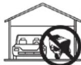

NEVER use inside a home or garage, EVEN IF doors and windows are open.
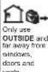
Only use OUTSIDE and far away from windows, doors, and vents.
SAFETY INSTRUCTIONS
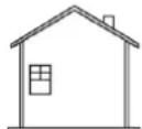
CORRECT USE
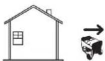
Example location to reduce risk of carbon monoxide poisoning
- ONLY use outside and downwind, far away from windows, doors and vents.
- Direct exhaust away from occupied spaces
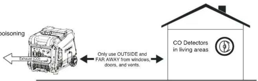
INCORRECT USE
Do not operate in any of the following locations:
- Near any door, window, or vent
- Garage
- Basement
- Crawl Space
- Living Area
- Attic
- Entry Way
- Porch
- Mudroom
flowchart
graph TD
    A["Vehicle"] --> B["Exhaust"]
    B --> C["Living Area"]
    C --> D["Basement Crawlspace"]
    D --> E["Entryway Porch Mud Room"]
    E --> F["Garage"]
    style A fill:#f9f,stroke:#333
    style B fill:#ccf,stroke:#333
    style C fill:#cfc,stroke:#333
    style D fill:#fcc,stroke:#333
    style E fill:#cff,stroke:#333
    style F fill:#ffc,stroke:#333
NOTICE
Install battery-powered carbon monoxide detectors or plug-in carbon monoxide detectors with battery back-up in living areas.
▲ DANGER
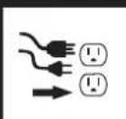
Fire and electrocution hazard. Do not connect to a building's electrical system unless the generator and transfer switch have been properly installed and the electrical output has been verified by a qualified electrician. The connection must isolate the generator power from utility power and must comply with all applicable laws and electrical codes.
DANGER
Electrocution hazard. Never use the generator in a location that is wet or damp. Never expose the generator to rain, snow, water spray, or standing water while in use. Protect the generator from all hazardous weather conditions. Moisture or ice can cause a short circuit or other malfunction in the electrical circuit.
GENERAL SAFETY PRECAUTIONS
- Never use the generator to power medical support equipment.
- Do not operate the generator when you are tired or under the influence of drugs, alcohol, or medication.
- Do not use generator with electrical cords which are worn, frayed, bare, or otherwise damaged.
- All electrical tools and appliances operated from this generator must be properly grounded by use of a third wire or be double-insulated.
- When this generator is used to supply a building wiring system the generator must be installed by a qualified electrician and connected to a transfer switch as a separately derived system in accordance with NFPA 70, National Electrical Code.
- If you begin to feel sick, dizzy, or weak while using the generator, move to fresh air IMMEDIATELY. See a doctor, as you can have carbon monoxide poisoning.
- Only use OUTSIDE and far away from windows, doors, and vents as recommended by the US Department of Health and Human Services Centers for Disease Control and Prevention. Your specific home and/or wind conditions may require additional distance.
- While operating and storing, keep at least 5 feet of clearance on all sides of the generator, including overhead. Allow the generator to cool a minimum of 30 minutes before storage. Heat created by the muffler and exhaust gases could be hot enough to cause serious burns and/or ignite combustible objects.
- Do not touch the muffler or engine. They are very HOT and will cause severe burns. Do not put body parts or any flammable or combustible materials in the direct path of the exhaust.
- Always remove any tools or other service equipment used during maintenance away from the generator before operating.
- Avoid skin contact with engine oil or gasoline. Wear protective clothing and equipment. Wash all exposed skin with soap and water.
- A transfer switch must be installed by a licensed electrician approved by the authority having jurisdiction. The installation must comply with all applicable laws and electrical codes.
FUEL SAFETY
- Store fuel in a container approved for gasoline.
- Do not smoke when filling the generator with gasoline.
- Do not allow the generator's gas tank to overflow when filling.
- Shut down the engine and allow it to cool for five minutes before adding gasoline or oil to the generator.
- Never remove the fuel cap when the generator is running. Shut off the engine and allow the unit to cool at least five minutes. Remove the fuel cap slowly to
6 | Westinghouse Outdoor Power Equipment, LLC
release pressure, keep fuel from escaping around the cap, and to avoid the heat from the muffler igniting fuel vapors. Tighten the fuel cap securely after refueling.
- Wipe spilled fuel from the unit.
- Never attempt to burn off spilled fuel.
- Never overfill the fuel tank. Leave room for fuel to expand. Overfilling the fuel tank can result in a sudden overflow of gasoline and result in spilled gasoline coming in contact with HOT surfaces.
- Spilled fuel can ignite. If fuel is spilled on the generator, wipe up any spills immediately. Dispose of rag properly. Allow area of spilled fuel to dry before operating the generator.
- Wear eye protection while refueling.
- Never use gasoline as a cleaning agent.
- Store any containers containing gasoline in a well-ventilated area, away from any combustibles or source of ignition.
Fire and explosion hazard. Gasoline is highly explosive and flammable and can cause severe burns or death.
- In case of a gas fire, do not attempt to extinguish the flame if the fuel tank valve is in the ON position. Introducing an extinguisher to a generator with an open fuel switch could create an explosion hazard.
- Gas has a distinctive odor, this will help detect potential leaks quickly.
• Gas vapors can cause a fire if ignited. - Gasoline is a skin irritant and needs to be cleaned up immediately if it comes in contact with the skin.
When starting the generator:
- Make sure that the fuel cap, air filter, spark plug, fuel lines, and exhaust system are properly in place.
- If you spill any gasoline on the tank, allow it to fully evaporate before operating.
- Make sure the generator is on a flat surface before operating.
When transporting or servicing the generator:
- Disconnect the spark plug wire to prevent accidental starting.
When storing the generator:
- Store away from sparks, open flames, pilot lights, heat, and other sources of ignition.
- Do not store gasoline near furnaces, water heaters, or any other appliances that produce heat or have automatic ignitions.
SAFETY LABELS AND DECALS

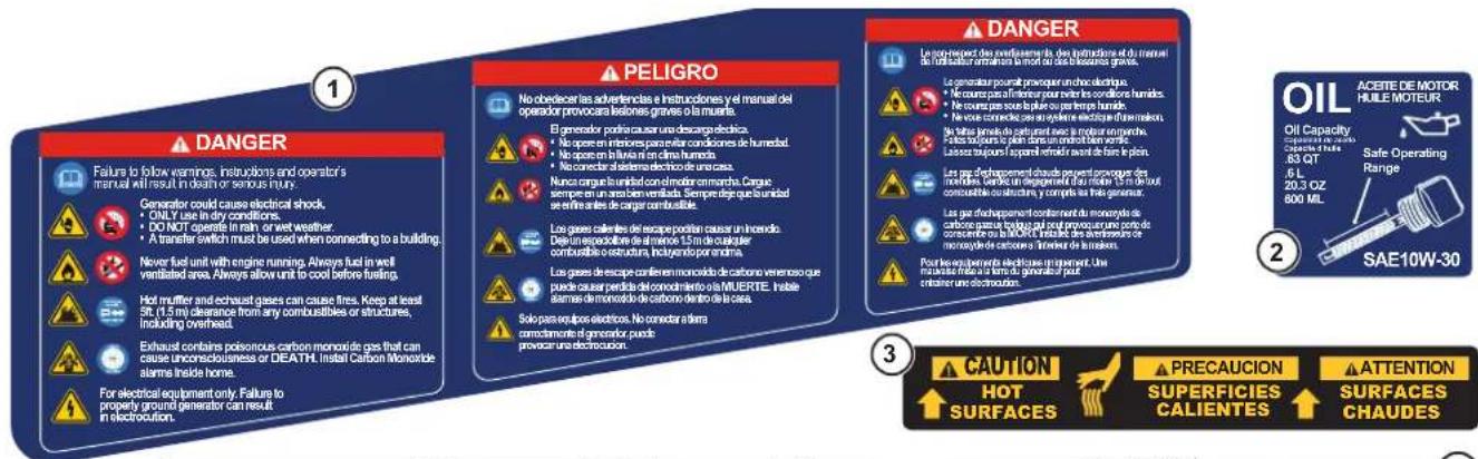


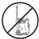
WARNING ⚠ PELIGRO ⚠ ATTENTION

Operate, store, and transport on firm level surface. Do not rest on exhaust panel. Tilting can cause fuel spillage
Using a generator indoors CAN KILL YOU IN MINUTES. Generator exhaust contains carbon monoxide. This is a vision you can not see or smelt. NEVER use inside a home or garage, EVEN IF doors and windows are open. Only use OUTSIDE and far away from windows, doors and ventis.
▲ PELIGRO
The CO sensor monitors for the accumulation of poisonous carbon monoxide gas around the generator when the engine is running. If increasing levels of CO gas are detected, the CO Sensor automatically shuts down the engine.
The CO Sensor will also detect the accumulation of carbon monoxide from other fuel burning sources used in the area of operation. For example, if the exhaust of fuel burning tools is pointed at a CO Sensor-equipped generator, a shut-off may be initiated due to rising CO levels. This is not an error. Hazardous carbon monoxide has been detected. Move and redirect any additional fuel burning sources to dissipate carbon monoxide away from personnel and occupied buildings.
Note: Remote start-equipped generators must be restarted with the START/STOP button on the control panel after an automatic shut-down occurs.
Generators are intended to be used outdoors, far from occupied buildings and the exhaust pointed away from personnel and buildings. If misused and operated in a location that results in the accumulation of CO, like in a partially enclosed area, the CO Sensor shuts off the engine, notifies the user with a RED indicator light, and directs the user to read the Action Label for steps to take. The CO Sensor DOES NOT replace carbon monoxide alarms. Install battery-powered carbon monoxide alarm(s) in your home.
WARNING
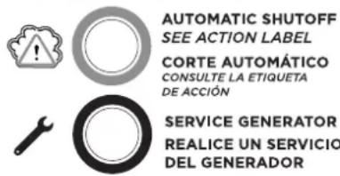
Automatic shutoff accompanied with a flashing RED light in the CO Sensor portion of the control panel is an indication that the generator was improperly located. If you start to feel sick, dizzy, weak, or carbon monoxide detectors in your home indicate an alarm, get to fresh air immediately. Call emergency services. You may have carbon monoxide poisoning.
CONTROL PANEL CO AUTO-SHUTOFF
CARBON MONOXIDE AUTO-SHUTOFF
CO SENSOR INDICATOR LIGHTS
Color Description
| RED | Carbon monoxide accumulated around the generator. After shut-off, the RED indicator light in the CO Sensor area of the control panel will flash to provide notification that the generator was shut-off due to an accumulating CO hazard. The RED light will flash for at least five minutes after a CO shut-off.Move the generator to an open, outdoor area far away from occupied spaces with exhaust pointed away. Once relocated to a safe area, the generator can be restarted. Introduce fresh air and ventilate the area where the generator had shut down. |
| YELLOW | A CO sensor system fault occurred. When a system fault occurs, the generator is automatically shut down and the YELLOW indicator light in the CO auto-shutoff area of the control panel will flash to provide notification that the a fault has occurred. The YELLOW light will flash for at least five minutes after a fault. The generator can be re-started, but may continue to shutoff. A CO sensor fault can only be diagnosed and repaired by an authorized Westinghouse service center. |
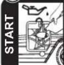
ACTION LABEL
ACTION LABEL
ETIQUETA DE FUNCIONAMIENTO ÉTIQUETTE D' ACTION
• MOVE GENERATOR TO AN OPEN, OUTDOOR AREA.
• POINT EXHAUST AWAY.
• DON'T RUN GENERATOR IN ENCLOSED AREAS (E.G. NOT IN HOUSE OR GARAGE).
- MOVER EL GENERADOR A UN ÁREA ABIERTA, EN EXTERIORES
- ORIENTAR EL TUBO DE ESCAPE HACÍA AFUERA
- NO ACTIVAR EL GENERADOR EN ÁREAS CERRADAS (P. EJ.: EN UNA CASA O GARAJE)
• DÉPLACER LA GÉNÉRATRICE DANS UN ESPACE EXTÉRIEUR OUVERT
• DIRIGER L'ÉCHAPPEMENT LOIN DE VOUS
- NE PAS FAIRE FONCTIONMER LA GÉNÉRATRICE DANS DES ENDROITS FERMÈS (COMME DANS LA MARION OU LE GARAGE)

WARNING ADVERTENCIA AVERTISSEMENT
TAMPERING WITH CARBON MONOXIDE SENSOR COULD RESULT IN HAZARDOUS CONDITION HACER ALTERACIONES CON SENSOR DE MONÓXIDO DE CARBONO PODRÍA OCASONAR CONDICIONES PELIGROSAS L'ALTÉRATION DE CAPTEUR DE MONOXYDE DE CARBONE PEUT ENTRAÎNER DES CONDITIONS DANGEREUSES

• MOVE TO FRESH AIR.
• GET MEDICAL HELP IF SICK.
DIZZY OR WEAK.
• MOVER AL AIRE LIBRE
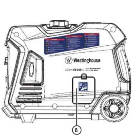
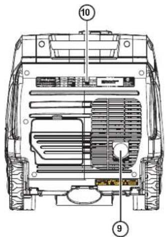
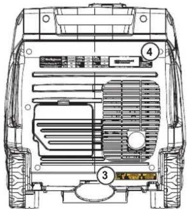
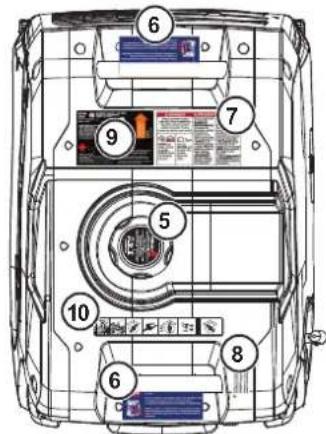
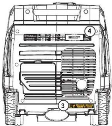
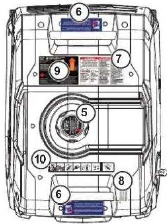
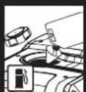
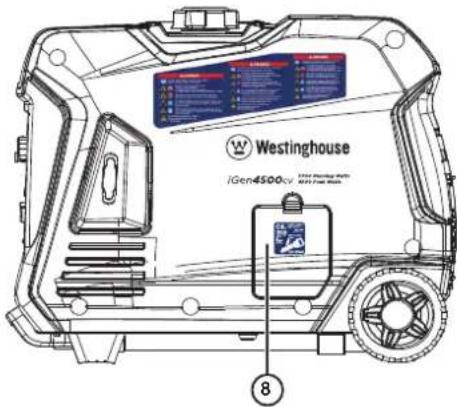
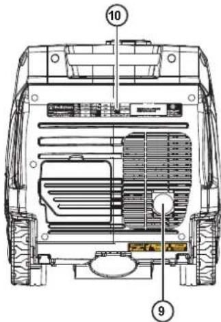
- Fuel Cap: Add unleaded fuel here. Close the cap until it clicks.
- Engine Service Cover: Cover provides access to the engine, air cleaner, carburetor, and spark plug.
- Transport Wheels: Wheels allow one-handed maneuverability when used with the extendable handle.
- Extendable Handle: Extend and retract the handle by pushing the locking button.
-
Carry Handles: Built-in handles allow easy, two-person transport.
-
Recoil Handle: Pull the recoil handle to manually start the engine.
- Control Panel: The control panel contains the outlets and operational controls.
- Oil Access Cover: Cover provides access to the oil fill cap/dipstick and oil drain plug.
- Muffler and Spark Arrestor: The spark arrestor prevents sparks from exiting the muffler.
- Model Information Label: Provides model serial number, voltage/amps, and power rating information.
DIGITAL DATA CENTER
Fuel remaining and power output percentage LEDs are continuously displayed. Push the Mode button to cycle through the data display modes.
DATA DISPLAY
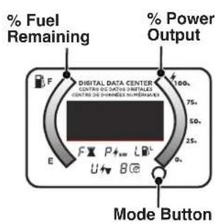


Remaining Run Time:
Displays time remaining with current fuel level and power output.
Power Output:
Displays electrical power output to receptacles in kilowatts.
Fuel level:
Displays current fuel level in liters.


Voltage:
Displays current voltage output of inverter.
Lifetime Hours:
Displays the total run time of the inverter.
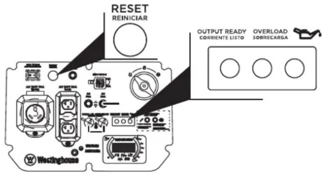
CONTROL PANEL COMPONENTS
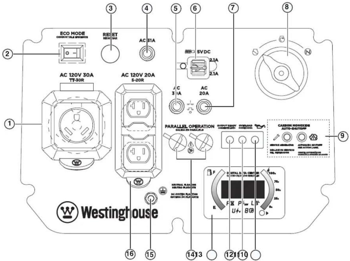
-
120 Volt AC, 30 Amp NEMA TT-30R Receptacle: Receptacle can supply a maximum of 30 Amps.
-
ECO Mode: Eco mode minimizes fuel consumption and noise by adjusting the engine RPM to the minimum required for the current load.
-
Overload Reset: The generator inverter will automatically switch OFF all AC output to protect the generator if overloaded or if there is a short circuit in a connected appliance.
-
Main Circuit Breaker: The main circuit breaker controls total output of all outlets to protect the generator from overload or short circuit.
-
USB Ports: Two-port 5V/2.1A USB outlet. Accepts Type A USB plugs.
-
20 Amp AC Circuit Breaker: Circuit breaker limits the current that can be delivered through the NEMA 5-20R receptacle to 20 Amps.
-
30 Amp AC Circuit Breaker: Circuit breaker limits the current that can be delivered through the NEMA TT-30 receptacle to 30 Amps.
-
CO Sensor indicator lights: The CO Sensor monitors for the accumulation of poisonous carbon monoxide gas. If increasing levels of CO gas are detected, the CO Sensor automatically shuts down the engine.
-
Low Oil LED: Indicates low oil level. When the oil level in the crankcase falls below the safe operating limit, the low oil level indicator will illuminate and the generator will automatically shut off the engine.
-
Overload LED: Indicates that the generator is overloaded.
-
Output Ready LED: Illuminates when the generator is operating normally. Indicates the generator is producing electrical power at the receptacles.
-
LED Data Center: Displays remaining run time (F), power output in kW (P), fuel level in liters (L), voltage output (V), and lifetime hours.
-
Parallel Operation Outlets: A compatible Westinghouse Inverter Generator can be connected for additional power output.
-
Ground Terminal: The ground terminal is used to externally ground the generator.
-
120 Volt AC, 20 Amp Duplex NEMA 5-20R Receptacle: Receptacle can supply a maximum of 20 Amps.
ASSEMBLY
CARTON CONTENTS
CAUTION
Weight hazard. Always have assistance when lifting the generator.
- Carefully open the carton.
- Remove and save the carton contents.
- Remove and discard the packing tray.
- Unfold the top of the plastic bag enclosing the generator.
- Carefully cut the vertical corners of the carton to access the generator.
- Recycle or dispose of the packaging materials properly.
CARTON CONTENTS
- User manual
- Quick Start Guide/Maintenance Schedule
• 0.63 Quart (0.6 Liter) bottle of SAE 10W-30 Oil - Spark plug socket wrench
- Oil Funnel
- Screwdriver
If any parts are missing, contact our service team at service@wpowereq.com or call 1-855-944-3571.
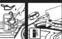
INITIAL OIL FILL
NOTICE
THIS GENERATOR HAS BEEN SHIPPED WITHOUT OIL. Do not attempt to crank or start engine before it has been properly serviced with recommended oil. Failure to add engine oil before starting will result in serious engine damage.
NOTICE
Use of 2-stroke/cycle oil or other unapproved oil types can cause severe engine damage that is not covered under warranty.
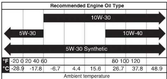
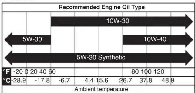
The included, recommended oil type for typical use is 10W-30 engine oil. If running the generator in extreme temperatures, refer to the following chart.
bar
Recommended Engine Oil Type | Oil Type | Ambient temperature (°C) | Ambient temperature (°F) | | :--- | :--- | :--- | | 5W-30 | -28.9 | -20 | | 5W-30 Synthetic | -17.8 | 20 | | 10W-30 | -6.7 | 40 | | 10W-30 Synthetic | 60 | 60 | | 10W-40 | 4.4 | 80 | | 10W-40 Synthetic | 15.6 | 100 | | Ambient temperature | 15.6 | 120 | | Ambient temperature | 26.7 | 26.7 | | Ambient temperature | 37.8 | 37.8 | | Ambient temperature | 48.9 | 48.9 |- On a level surface, remove the oil access cover and oil dipstick.
natural_image
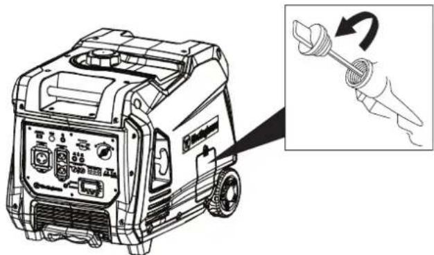
Line drawing of a portable electricity generator with a hand holding a screwdriver (no text or symbols present)- Using the supplied funnel and oil, add oil into the engine.
Note: As residual oil from the factory may remain in the engine, add the oil incrementally near the end of the bottle to prevent overfilling the engine. See Engine Oil Level Check in the Maintenance section.
-
Replace the oil dipstick and hand-tighten.
-
Replace the oil access cover.
FUEL
WARNING
Fire and explosion hazard. Never use a gasoline container, gasoline tank, or any other fuel item that is broken, cut, torn or damaged.
DANGER
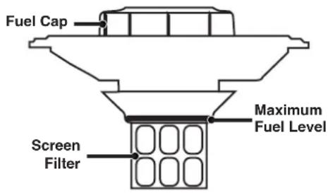
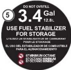
Fire and explosion hazard. Do not overfill fuel tank. Fill only to the red fill ring located in the in-tank fuel screen filter. Overfilling may cause fuel to spill onto engine causing a fire or explosion hazard.
DANGER
Fire and explosion hazard. Never refuel the generator while the engine is running. Always turn the engine off and allow the generator to cool for two minutes before refueling.
NOTICE

Do not use E15 or E85 fuel in this product. Engine or equipment damage caused by stale fuel or the use of unapproved fuels (such as E15 or E85 ethanol blends) is not covered by warranty. Only use unleaded gasoline containing up to 10% ethanol.
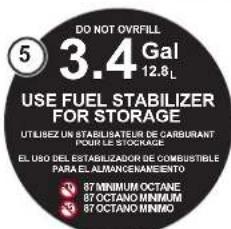
FUEL REQUIREMENTS
- CLEAN, FRESH, unleaded gasoline, 87–93 octane.
- Up to 10% ethanol (gasohol) is acceptable (where available; non-ethanol fuel is recommended).
• DO NOT use E85 or E15.
• DO NOT use a gas oil mix. - DO NOT modify the engine to run on alternate fuels.
• DO NOT fuel indoors. - DO NOT create a spark or flame while fueling.
USING FUEL STABILIZER
Adding a fuel stabilizer (not included) extends the usable life of fuel and helps prevent deposits from forming that can clog the fuel system. Follow the manufacturer's instructions for use.
Always mix the correct amount of fuel stabilizer to gasoline in an approved gasoline container before fueling the generator. Run the generator for five minutes to allow the stabilizer to treat the entire fuel system.
FILLING THE FUEL TANK
- Turn the generator OFF and allow to cool for a minimum of two minutes before fueling.
- Place the generator on level ground in a well ventilated area.
- Clean area around fuel cap and remove the cap slowly.
NOTICE
Only fill the tank from an approved gasoline container. Make sure the gasoline container is internally clean and in good condition to prevent fuel system contamination.
- Slowly add the recommended fuel. Do not overfill. Fill only to the red maximum fill ring on the fuel screen filter visible in the filler neck.
- Install the fuel cap. Tighten securely.
NOTICE
Fuel can damage paint and plastic. Use caution when filling the fuel tank. Damage caused by spilled fuel is not covered under warranty.
NOTICE
Clean the fuel screen filter of debris before and after each fueling. Remove the fuel screen filter by slightly compressing it while removing it from the fuel tank.
OPERATION
GENERATOR LOCATION
Read and understand all safety information before starting the generator.
DANGER
Using a generator indoors CAN KILL YOU IN MINUTES. Generator exhaust contains carbon monoxide. This is a poison you cannot see or smell.

NEVER use inside a home or garage, EVEN IF doors and windows are open.
Only use OUTSIDE and far away from windows, doors, and vents.
NEVER operate the generator inside any building, including garages, basements, crawlspaces, sheds, enclosure, or compartment, including the generator compartment of a recreational vehicle.
DANGER
Electrocution hazard. Never use the generator in a location that is wet or damp. Never expose the generator to rain, snow, water spray, or standing water while in use. Protect the generator from all hazardous weather conditions. Moisture or ice can cause a short circuit or other malfunction in the electrical circuit. Using a generator or electrical appliance in wet conditions, such as rain or snow, or near a pool or sprinkler system, or when your hands are wet, could result in electrocution
WARNING
Fire hazard. Only operate the generator on a solid, level surface. Operating the generator on a surface with loose material such as sand or grass clippings can cause debris to be ingested by the generator that could block cooling vents or the air intake system. Allow the generator to cool for 30 minutes before transport or storage.
The generator should be on a flat, level surface at all times (Even while not in operation). The generator must have at least 5 ft. (1.5 m) of clearance from all combustible material.
Do not operate the generator in the back of a SUV, camper, trailer, truck bed (regular, flat, or otherwise), under stairs, next to walls or buildings, or in any other location that will not allow for adequate cooling of the generator and/or the muffler. DO NOT contain generators during operation.
▲ DANGER
Asphyxiation hazard. Place the generator in a well-ventilated area. DO NOT place the generator near vents or intakes where exhaust fumes could be drawn into occupied or confined spaces. Carefully consider wind and air currents when positioning generator.
GROUNDING
WARNING
Shock hazard. Failure to properly ground the generator can result in electric shock.
NOTICE
Only use grounded 3-prong extension cords, tools, and appliances, or double-insulated tools and appliances.
The generator neutral is floating. The generator ground terminal is connected to the frame of the generator, the metal non-current-carrying parts of the generator, and the ground terminals of each receptacle. The generator (stator winding) is isolated from the frame and from the AC receptacle ground pin. Electrical devices that require a grounded receptacle pin connection may not function properly.
If this generator will be used only with cord and plug equipment connected to the receptacles mounted on the generator, National Electric Code does not require that the unit be grounded. However, other methods of using the generator may require grounding to reduce the risk of shock or electrocution.
Before using the ground terminal, consult a qualified electrician, electrical inspector, or local agency having jurisdiction for local codes or ordinances that apply to the intended use of the generator.
Engine power is reduced the higher you operate above sea level. Output will be reduced approximately 3.5% for every 1000 feet of increased altitude from sea level.
High altitude adjustment is required for operation at altitudes over 2000 ft. (762 m). Operation without this adjustment will cause decreased performance, increased fuel consumption, and increased emissions.
NOTICE
DO NOT operate the generator at altitudes below 2,000 ft. (762 m) with the high altitude kit installed. Engine damage may occur.
High Altitude Carburetor Kit: Part# 518916-01
BREAK-IN PERIOD
For proper break-in, do not exceed 50% of the rated running watts (1850 watts) during the first five hours of operation.
Vary the load occasionally to allow stator windings to heat and cool and help seat the piston rings.
BEFORE STARTING THE GENERATOR
Verify that:
• The generator is placed in a safe, appropriate location.
• The generator is on a dry, flat, and level surface.
• The engine is filled with oil.
• Gasoline is in the fuel tank.
- All loads are disconnected.
• The ECO switch is in the OFF position.
▲ DANGER
Fire and explosion hazard. DO NOT move or tip the generator during operation.
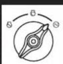
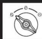
STARTING THE ENGINE
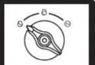
- Turn the fuel knob to the choke position.
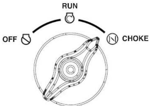
flowchart
graph TD
    A["OFF"] --> B["RUN"]
    B --> C["CHOKE"]
    style A fill:#f9f,stroke:#333
    style B fill:#ccf,stroke:#333
    style C fill:#cfc,stroke:#333
Note: The generator can be started from the Run position if warm from operation.
- Firmly grasp and pull the recoil handle slowly until you feel increased resistance, then pull rapidly.
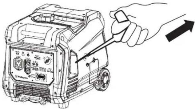
natural_image
Line drawing of a portable electricity generator with a hand holding a screwdriver (no text or symbols)- After the engine starts, turn the fuel knob to the RUN position.
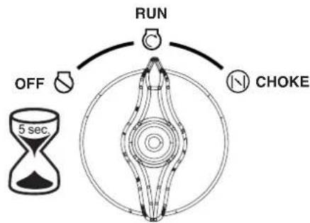
flowchart
graph TD
    A["RUN"] --> B["OFF"]
    B --> C["C/NO"]
    C --> D["CHOKE"]
    style A fill:#f9f,stroke:#333
    style B fill:#ccf,stroke:#333
    style C fill:#cfc,stroke:#333
    style D fill:#fcc,stroke:#333
STOPPING THE ENGINE
- Turn off and unplug all connected electrical loads.
IMPORTANT: Never start or stop the generator with electrical devices connected.
-
Let the generator run with no load for several minutes to stabilize internal temperatures of the engine and generator.
-
Turn the fuel knob to the OFF position.
-
Allow the engine to cool, then turn the fuel cap vent to the OFF position.
Note: If there is an emergency and the inverter must be stopped quickly, immediately move the fuel switch to the OFF position.
FREQUENCY OF USE
If the generator will be used on an infrequent or intermittent basis (more than one month before next use), refer to the Storage sections of this manual for information regarding fuel deterioration.
ECO MODE
NOTICE
Always start the generator with ECO MODE OFF. Allow the engine speed to stabilize and the OUTPUT READY LED to illuminate before switching ECO MODE ON.
ECO MODE
COMBUSTIBLE EFICIENTE
COMMUTATEUR D'ÉCONOMIE
Note: Do not use ECO MODE when in parallel operation with another Westinghouse generator.
ECO MODE minimizes fuel consumption and noise by adjusting the engine RPM to the minimum required for the current load.
Turn ECO MODE ON when powering small appliances with continuous loads such as a computer or electric light.
Turn ECO MODE OFF when powering large surge loads such as an air conditioner or electric pump.
To turn on ECO MODE, verify that the OUTPUT READY LED is illuminated green, then push the switch to the ON position. If no load is present, the generator RPM will drop to idle speed. The generator will detect loads as they are applied and increase engine RPM.
To run the generator at maximum power and RPM, push the ECO MODE switch to the OFF position.
AC CIRCUIT BREAKERS
The circuit breakers will automatically switch OFF if there is a short circuit or a significant overload of the generator at each receptacle. The main circuit breaker will automatically switch OFF if the combined load of the receptacles exceeds 31 Amps.
If an AC circuit breaker switches OFF automatically, check that the appliance is working correctly and it does not exceed the rated load capacity of the circuit before resetting the AC circuit breaker ON.

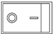
OVERLOAD RESET
The generator will automatically switch OFF all AC output to protect the generator if overloaded or if there is a short circuit in a connected appliance. However, the engine will continue to run. Marginal overloading that temporarily illuminates the OVERLOAD LED may shorten the service life of the generator.
OVERLOAD on the control panel will illuminate red and the green OUTPUT READY will be OFF.
To restore AC output:
- Turn off and unplug all connected electrical loads.
- Push the RESET button on the control panel until the OVERLOAD LED goes OFF and the OUTPUT READY LED is illuminated.
- Reset the circuit breakers if OFF.
- Verify that the intended running and surge loads do not exceed the generator's capacity.
- Reconnect electrical loads sequentially, allowing the generator to stabilize after each load is connected.
GENERATOR CAPACITY
NOTICE
Do not overload the generator's capacity. Exceeding the generator's wattage/amperage capacity can damage the generator and/or electrical devices connected to it.
Make sure the generator can supply enough continuous (running) and surge (starting) watts for the items you will power at the same time.
The total power requirements (Volts x Amps = Watts) of all appliances connected must be considered. Appliance and power tool manufacturers usually list rating information near the model or serial number.
To determine power requirements:
- Select the items you will power at the same time.
- Total the continuous (running) watts of these items. This is the amount of power the generator must produce to keep the items running. See the wattage reference chart on the next page.
- Estimate how many surge (starting) watts you will need. Surge wattage is the short burst of power needed to start electric motor-driven tools or appliances such as a circular saw or refrigerator. Because not all motors start at the same time, total surge watts can be estimated by adding only the item(s) with the highest additional surge watts to the total rated watts from step 2.
Example:
| Tool or Appliance | Running Watts* | Starting Watts* |
| RV Air Conditioner (11,000 BTU) 1010 1600 | ||
| TV (Tube Type) 300 0 | ||
| RV Refrigerator 180 600 | ||
| Radio 200 0 | ||
| Light (75 Watts) 300 0 | ||
| Coffee Maker 600 0 | ||
| 2590 Total | 1600 | |
| Running Watts* | Highest Starting Watts* | |
Total Running Watts 2590
Highest Starting Watts + 1600
Total Starting Watts Needed 4190
*Wattages listed are approximate. Verify actual wattage.
POWER MANAGEMENT
To prolong the life of the generator and attached devices, use care when adding electrical loads to the generator. There should be nothing connected to the generator outlets before starting the engine. The correct and safe way to manage generator power is to sequentially add loads as follows:
- With nothing connected to the generator, start the engine as described in this manual.
- Plug in and turn on the first load, preferably the largest load you have.
- Permit the generator output to stabilize (engine runs smoothly and attached device operates properly).
- Plug in and turn on the next load.
- Again, permit the generator to stabilize.
- Repeat steps 4 and 5 for each additional load.
Wattage Reference
| Tool or Appliance | Estimated Running Watts* | Estimated Starting Watts* |
| Incandescent Lights(4 Quantity x 75 Watts) | 300 0 | |
| TV (Tube Type) 300 0 | ||
| Sump Pump (1/3 hp) | 800 | 1300 |
| Refrigerator or Freezer | 700 | 2200 |
| Well Pump (1/3 hp) | 1000 | 2000 |
| Furnace (1/2 hp) | 800 | 2350 |
| Radio | 200 0 | |
| Drill (3/8", 4 amps) | 440 | 600 |
| Circular Saw(Heavy Duty, 7-1/4") | 1400 | 2300 |
| Miter Saw (10") | 1800 | 1800 |
| Table Saw (10") | 2000 | 2000 |
*Wattages listed are approximate. Verify actual wattage.
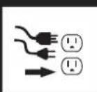
EXTENSION CORDS
WARNING
Asphyxiation hazard. Extension cords running directly into the home increase the risk of carbon monoxide poisoning through any openings. If an extension cord running directly into your home is used to power indoor items, there is a risk of carbon monoxide poisoning to people inside the home. Always use battery-powered carbon monoxide detector (s) that meet current UL 2034 safety standards when running the generator. Regularly check the detector (s) battery.
▲WARNING
Asphyxiation hazard. When operating the generator with extension cords, make sure the generator is located in an open, outdoor area, at least 20 ft. (6 m.) far away from occupied spaces with exhaust pointed away.
▲ WARNING
Fire and electrocution hazard. Never use worn or damaged extension cords. Damaged or overloaded extension cords could overheat, arc, and burn resulting in death or serious injury.
Before connecting an AC appliance or power cord to the generator:
- Use grounded 3-prong extension cords, tools, and appliances, or double-insulated tools and appliances.
- Make sure the tool or appliance is in good working order. Faulty appliances or power cords can create a potential for electric shock.
- Make sure the electrical rating of the tool or appliance does not exceed the rated power of the generator or the receptacle being used.
EXTENSION CORD SIZING
Only use grounded 3-prong extension cords marked for outdoor use that are rated for the electrical load.
| Total Amperage | Minimum Gauge, Outdoor Rated | |
| Up to 50 FT (15 M) | Up to 100 FT (30 M) | |
| Up to 10A | [G2xH] | [XABK] |
| Up to 15A |  |  |
| Up to 20A | [BHTW] |  |
| Up to 30A |  | [Y3BK] |
| Up to 35A | [WBA8] |  |
PARALLEL OPERATION
WARNING
Fire and electrocution hazard. Never connect or disconnect the parallel cord leads when a generator is running.
CAUTION
Correct connection of the left and right cables is very important when the generators are used with a transfer switch to supply power to a building. To avoid serious personal injury or damage to electrical devices, including the generators, do not try to power an electrical system in a building without using an approved transfer switch.
NOTICE
Connecting to a generator that is not compatible can cause a low voltage output that can damage tools and appliances powered by the generator.
Parallel operation gives you the ability to link to a compatible Westinghouse Inverter Generator for combined running and peak power output.
A Westinghouse 507PC parallel cord (purchased separately) is required for parallel operation. This cord can be purchased from an authorized Westinghouse Generator dealer.
Note: Compatible Westinghouse generators without parallel ports can be operated in parallel with the receptacle-mounted parallel cable, Part# 260041.
NOTICE
DO NOT use ECO MODE during parallel operation if powering large surge loads such as an air conditioner or electric pump. Engine rpm may not adjust quickly enough to provide the voltage requirements of large surge loads, causing damage to the devices or the generators.
- On both generators, make sure the fuel knob and the ECO MODE switch are in the OFF position.
- Connect two parallel cable leads to the parallel outlets on the first generator, then connect the opposite cable leads to the other generator's parallel outlets.
Note: If powering devices directly from the generators (not connected to a building's transfer switch), you do not need to match the left/right cables to the generator's parallel outlets.
-
Start one of the generators and wait until the OUTPUT READY LED illuminates.
-
Start the second generator and wait until the OUTPUT READY LED illuminates before connecting a load.
-
Connect additional loads as described in Power Management section.
-
Unplug all loads before stopping the generators.
TRANSPORTING
▲ CAUTION
Weight hazard. Always have assistance when lifting the generator.
- Allow the generator to cool a minimum of 30 minutes before transporting.
- Replace all protective covers on the generator control panel.
- Only use the generator's fixed handle(s) to lift the unit or attach any load restraints such as ropes or tie-down straps. Do not attempt to lift or secure the generator by holding onto any of its other components.
- Keep the unit level during transport to minimize the possibility of fuel leakage or, if possible, drain the fuel or run the engine until the fuel tank is empty before transport.
- The generator wheels are only intended for hand transport. The wheels are not suitable for towing the generator either on or off-road.
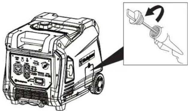
- Use the extendable handle for one-person, hand transport. To deploy the handle, push on the locking button and pull on the handle until it's fully extended. To stow it, push on the locking button and push on the handle until it's fully retracted. Only extend or retract the handle while the generator is OFF, stationary, and resting on a horizontal surface. Do not use the extendable handle to lift the generator entirely off the ground, tow it, or up-end it.
CAUTION
Fire hazard. Do not up-end the generator or place it on its side. Fuel or oil can leak and damage to the generator may occur.
MAINTENANCE
WARNING
Accidental start-up. Disconnect the spark plug boot from the spark plug when performing maintenance on the generator.
MAINTENANCE SCHEDULE
Regular maintenance will improve performance and extend the service life of the generator. Follow the hourly or calendar intervals, whichever occurs first. More frequent service is required when operating in adverse conditions as noted below.
Before Each Use
Check engine oil
After First 25 Hours or First Month
Change engine oil
After 50 Hours or Every 6 Months
Change engine oil ^1
Clean air filter ^2
After 100 Hours or Every 6 Months
Inspect/clean spark arrestor
Inspect/clean spark plug
Replace fuel filter ^3
Inspect/adjust valve clearance ^3
After 300 Hours or Every Year
Replace spark plug
Replace air filter
1 Change oil every month when operating under heavy load or in high temperatures.
2 Clean more often under dirty or dusty conditions. Replace air filter if it cannot be adequately cleaned.
^3 Recommend service to be performed by authorized Westinghouse service dealer.
MAINTENANCE REPLACEMENT PARTS
Description Part Number
| Foam air filter 5691 | |
| Oil drain plug crush washer 940 | 07 |
| Spark arrestor 6790 | |
| Spark plug F7RTC |
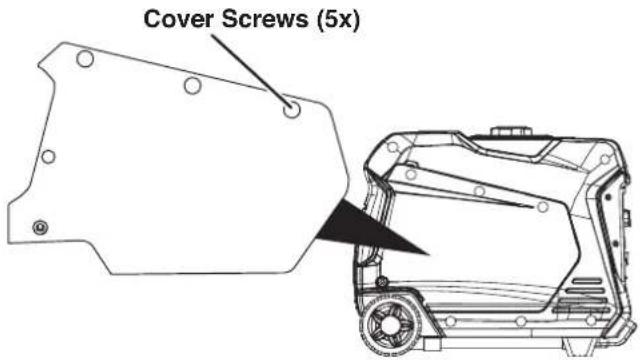
ENGINE SERVICE COVER
Remove the engine service cover to access the air filter, carburetor, and spark plug. Remove the cover screws then pull the cover straight out with both hands to prevent damage to the grommet posts on the cover.
AIR FILTER MAINTENANCE
WARNING
Fire hazard. Never use gasoline or other flammable solvents to clean the air filter. Use only household detergent soap to clean the air filter.
The air filter must be cleaned after every 50 hours of use or six months (frequency should be increased if the generator is operated in a dusty environment).
- Place the generator on a level surface and allow the engine to cool for several minutes.
- Remove the engine service cover.
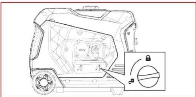
- Turn the knobs on the air cleaner cover to the unlocked position. Tip the cover down to remove.
natural_image
Technical line drawing of a vehicle chassis with internal components and a circular dial indicator (no text or symbols)Note: The air filter element is oil soaked. Use an appropriate cleaning container.
NOTICE
Avoid skin contact with engine oil. Wear protective clothing and equipment. Wash all exposed skin with soap and water.
- Remove the foam air filter from the air cleaner housing and wash it by submerging the element in a solution of household detergent soap and warm water. Slowly squeeze the foam to thoroughly clean.
NOTICE
DO NOT twist or tear the foam air filter element during cleaning or drying. Only apply slow but firm squeezing action.
- Rinse the air filter element by submerging it in fresh water and applying a slow squeezing action. Allow the filter to dry thoroughly.
NOTICE
Do not pollute. Follow the guidelines of the EPA or other governmental agencies for proper disposal of hazardous materials. Consult local authorities or reclamation facility.
- Dip the foam air filter in clean engine oil then squeeze out all excess oil. The engine will smoke when started if too much oil is left in the filter.
- Install the foam air filter in the housing and lock the air cleaner cover in place.
- Install the engine service panel.
Air Filter: Part# 5691
ENGINE OIL LEVEL CHECK
▲ CAUTION
Avoid skin contact with engine oil. Wear protective clothing and equipment. Wash all exposed skin with soap and water.
NOTICE
Always use the specified engine oil. Failure to use the specified engine oil can cause accelerated wear and/or shorten the life of the engine.
When using the generator under extreme, dirty, dusty conditions or in extremely hot weather, change the oil more frequently.
Ambient air temperature will affect engine oil performance. Change the type of engine oil used based on weather conditions.
bar
Recommended Engine Oil Type | Oil Type | Ambient temperature (°C) | Ambient temperature (°F) | | :--- | :--- | :--- | | 5W-30 | -28.9 | -20 | | 5W-30 Synthetic | -17.8 | 20 | | 5W-30 Synthetic | -6.7 | 40 | | 5W-30 Synthetic | 4.4 | 60 | | 10W-30 | 4.4 | 80 | | 10W-30 Synthetic | 15.6 | 100 | | 10W-30 Synthetic | 120 | 120 | | 10W-40 | 26.7 | 37.8 | | 10W-40 Synthetic | 37.8 | 48.9 | | Ambient temperature | 48.9 | — |Check the engine oil level before each use or every 8
hours of operation.
- Place the generator on a level surface and allow the engine to cool for several minutes.
- Remove the oil access cover.
- With a damp rag, clean around the oil dipstick.
- Remove the oil dipstick and wipe the dipstick clean.
natural_image
Line drawing of a portable electricity generator with a hand holding a screwdriver (no text or symbols present)- Screw the dipstick fully into the filler neck. Remove the dipstick and verify that the oil level is within safe operating range.
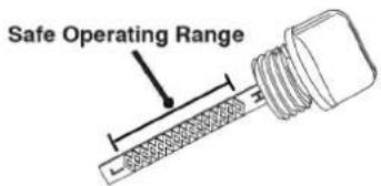
- If low, add recommended engine oil incrementally and recheck until the level is between the L and H marks on the dipstick. DO NOT overfill. If over the full mark on dipstick, drain the oil to reduce oil level to the full mark on dipstick.
- Replace the oil dipstick and hand-tighten.
- Install the oil access cover.
ENGINE OIL CHANGE
When using the generator under extreme, dirty, dusty conditions or in extremely hot weather, change the oil more frequently. Change the oil while the engine is still warm from operation.
- Place the generator on a level surface and allow the engine to cool for several minutes.
- Remove the engine service cover. Disconnect the spark plug wire from the spark plug and place the wire where it cannot contact the spark plug.
- Remove the oil access cover.
- With a damp rag, clean around the oil dipstick. Remove the dipstick and wipe clean.
- Remove the rubber plug under the oil drain bolt and place an oil pan (or suitable container) under the drain hole.
- Using a 10mm wrench, remove the oil drain bolt and allow the oil the to drain.
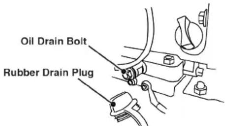
- Install the oil drain plug and tighten securely. Install the rubber plug.
Note: A new oil drain plug crush washer is recommended at each oil change.
Drain plug crush washer: Part# 94007
- Slowly pour oil into the oil fill opening until oil the level is between the L and H marks on the dipstick. Stop frequently to check the oil level. DO NOT overfill.
Maximum oil capacity: 0.63 US qt (0.60 L)
-
Replace the dipstick and hand-tighten.
-
Connect the spark plug wire and install the engine service cover.
NOTICE
Do not pollute. Follow the guidelines of the EPA or other governmental agencies for proper disposal of hazardous materials. Consult local authorities or reclamation facility.
SPARK PLUG MAINTENANCE
Inspect and clean the spark plug after every 100 hours of use or six months. Replace the spark plug after 300 hours of use or every year.
NOTICE
ALWAYS use the Westinghouse OEM or compatible non-resistor-type spark plug. Use of resistor-type spark plug can result in rough idling, misfire, or may prevent the engine from starting.
- Place the generator on a level surface and allow the engine to cool.
- Remove the engine service cover.
- Remove the spark plug boot by firmly pulling the spark boot directly away from the engine.
- Clean the area around the spark plug.
- Remove the spark plug with the included spark plug socket wrench.
NOTICE
Never apply any side load or move the spark plug laterally when removing the spark plug.
- Inspect the spark plug. Replace if electrodes are pitted, burned, or the insulator is cracked. Only use a recommended replacement plug.
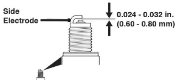
- Measure the spark plug electrode gap with a wire-type feeler gauge. If necessary, correct the gap by carefully bending the side electrode.
Spark plug gap: 0.024 - 0.032 in. (0.60 - 0.80 mm)
- Carefully install the spark plug finger tight, then tighten as additional 3/8 to 1/2 turn with the spark plug wrench.
- Install the spark plug boot and engine service cover.
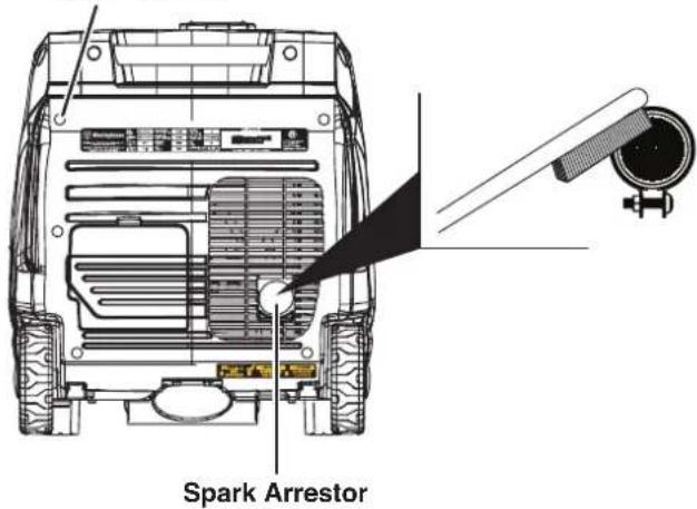
SPARK ARRESTOR SERVICE
Check and clean the spark arrestor after every 100 hours of use or six months. Failure to clean the spark arrestor will result in degraded engine performance.
- Place the generator on a level surface and allow the muffler to cool before servicing the spark arrestor.
- Remove the cover screws and the muffler cover. Use a screw driver to remove the spark arrestor.
- Carefully remove the carbon deposits from the spark arrestor screen with a wire brush. The spark arrestor must be free of breaks and tears. Replace the spark arrestor if damaged.
Cover Screws
Spark Arrestor: Part# 6790
- Reinstall the spark arrestor and muffler cover.
STORAGE
Proper storage preparation is required for trouble-free operation and generator longevity.
NOTICE
Gasoline stored for as little as 30 days can deteriorate, causing gum, varnish, and corrosive buildup in fuel lines, fuel passages and the engine. This corrosive buildup restricts the flow of fuel, which can prevent the engine from starting after a prolonged storage period. The use of fuel stabilizer significantly increases the storage life of gasoline. Full-time use of fuel stabilizer is recommended. Follow the manufacturer's instructions for use.
STORAGE TIME RECOMMENDED PROCEDURE
| Less than 1 month No | service required. |
| 2 to 6 months | Fill with fresh gasoline and add gasoline stabilizer. Drain the carburetor float bowl. |
STORAGE TIME RECOMMENDED PROCEDURE
| 6 months or longer | Drain the fuel tank and carburetor float bowl. |
SHORT TERM STORAGE
- Allow the generator to cool a minimum of 30 minutes before storage.
- Replace all protective covers on the generator control panel.
- Wipe the generator with a moist cloth. Clean any debris from the air inlets under the control panel and muffler cooling vents.
- Store the generator in a well-ventilated, dry location away from sparks, open flames, pilot lights, heat, and other sources of ignition such as areas with a spark-producing electric motor or where power tools are operated.
- Do not store the generator or gasoline near furnaces, water heaters, or any other appliances that produce heat or have automatic ignitions.
- With the engine and exhaust system cool and all surfaces dry, cover the generator to keep out dust. Do not use a plastic sheet as a dust cover. Non-porous materials trap moisture and promote rust and corrosion.
LONG TERM STORAGE
Even properly stabilized fuel can leave residue and cause corrosion if left long term. If storing the generator for two to six months, drain the float bowl to prevent gum and varnish buildup in the carburetor.
DRAINING THE FLOAT BOWL
- Remove the engine service cover.
- Locate the drain hose extending from the bottom of the carburetor float bowl.
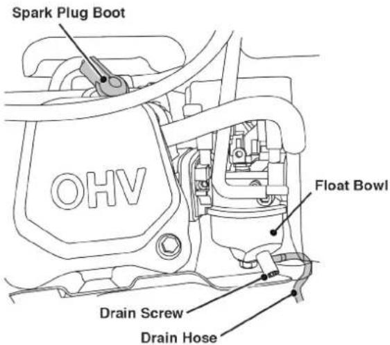
- Place the loose end of the hose outside the generator into an approved gasoline container to catch the drained fuel.
- Loosen the float bowl drain screw and allow the fuel to drain. Tighten the float bowl drain screw.
- Route the drain hose between the air cleaner housing and the engine service cover. Install the engine service cover.
DRAINING THE FUEL TANK
If storing the generator for longer than six months, drain the fuel tank to prevent fuel separation, deterioration, and deposits in the fuel system.
- Unscrew the fuel tank cap. Remove the fuel screen filter by slightly compressing it while removing it from the tank.
-
Using a commercially available gasoline hand pump (not included), siphon the gasoline from the fuel tank into an approved gasoline container. DO NOT use an electric pump.
-
Reinstall the fuel screen filter and the fuel tank cap.
-
Start the generator and allow it to run until the generator engine stops.
-
Remove the spark plug.
-
Put a teaspoon of engine oil into the cylinder and pull the recoil handle until resistance is felt. At this position the piston is coming up on its compression stroke and both valves are closed. Storing the engine in this position will help prevent internal corrosion. Return the recoil handle gently.
-
Reinstall the spark plug. Leave the spark plug boot disconnected to prevent accidental starting.
-
Install the engine service cover.
VALVE CLEARANCE
NOTICE
Checking and adjusting valve clearance must be done when the engine is cold.
- Remove the rocker arm cover and carefully remove the gasket. If the gasket is torn or damaged, it must be replaced.
- Remove the spark plug so the engine can be rotated more easily.
- Rotate the engine to top dead center (TDC) by pulling the recoil handle slowly. Looking through the spark plug hole, the piston should be at the top (both valves are closed).
- Both the rocker arms should be loose at TDC on the compression stroke. If they are not, rotate the engine 360°.
- Insert a feeler gauge between the rocker arm and the valve stem to measure valve clearance.
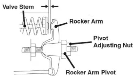
Intake Valve Exhaust Valve
| Valve Clearance | 0.0031 – 0.0047 in(0.08 – 0.12 mm) | 0.0051 – 0.0067 in(0.13 – 0.17 mm) |
| Torque 8-12 N·m 8-12 N·m | ||
-
If an adjustment is necessary, hold the rocker arm pivot and loosen the pivot adjusting nut.
-
Turn the rocker arm pivot to obtain the specified clearance. Hold the rocker arm pivot and re-tighten the pivot adjusting nut to the specified torque.
Torque: 106 inch-pound (12 N·m)
-
Perform this procedure for the other valve.
-
Install the gasket, rocker arm cover, and spark plug.
-
Perform this procedure for the other valve.
- Install the gasket, rocker arm cover, and spark plug.
TROUBLESHOOTING
TROUBLESHOOTING
| PROBLEM POSSIBLE CAUSE CORRECTION | ||
| Engine will not start | Out of fuel. Refuel. | |
| Bad fuel, generator stored without treating or draining gasoline, or refueled with bad gasoline. | Drain the fuel tank. Refuel with fresh gasoline. | |
| Dirty air filter. Clean the air filter. | ||
| Low engine oil level stopped generator. | If low oil LED illuminated, turn battery switch to the OFF position. Add engine oil. | |
| Spark plug wet with fuel (flooded engine). | Wait five minutes. Turn battery switch to the OFF position. Pull recoil handle rapidly several times. If the generator does not start, remove spark plug and dry. | |
| Spark plug faulty, fouled, or improperly gapped. | Gap or replace the spark plug. Reinstall. | |
| Fuel filter restricted, fuel system malfunction, fuel pump failure, ignition malfunction, valves stuck, etc. | Contact Westinghouse customer service toll-free at 1 (855) 944-3571. | |
| CO sensor removed or modified. Return to original configuration. | ||
| CO sensor activated or system fault occurred. | Relocate generator/Contact Westinghouse customer service toll-free at 1 (855) 944-3571. | |
| Engine starts, then shuts down | Out of fuel. Refuel. | |
| Incorrect engine oil level. Check engine oil level. | ||
| Dirty air filter. Clean the air filter. | ||
| Contaminated fuel. Drain the fuel tank. Refuel with fresh gasoline. | ||
| Defective low oil level switch. | Contact Westinghouse customer service toll-free at 1 (855) 944-3571. | |
| Engine lacks power | Air filter restricted. Clean or replace air filter. | |
| Bad fuel, generator stored without treating or draining gasoline, or refueled with bad gasoline. | Drain the fuel tank. Refuel with fresh gasoline. | |
| Fuel filter restricted, fuel system malfunction, fuel pump failure, ignition malfunction, valves stuck, etc. | Contact Westinghouse customer service toll-free at 1 (855) 944-3571. | |
| Engine runs rough or bogs when load applied | Dirty air filter. Clean the air filter. | |
| Generator overloaded. Unplug some devices. | ||
| Faulty power tool or appliance. | Replace or repair tool or appliance. Stop and restart the engine. | |
| Fuel filter restricted, fuel system malfunction, fuel pump failure, ignition malfunction, valves stuck, etc. | Contact Westinghouse customer service toll-free at 1 (855) 944-3571. | |
| No power at AC receptacles | OUTPUT READY LED is OFF and OVERLOAD LED is ON. | Check AC load. Stop and restart engine. |
| Check the air inlet. Stop and restart the engine. | ||
| AC circuit breaker/s tripped. Check AC loads and reset circuit breaker/s. | ||
| Faulty power tool or appliance. | Replace or repair tool or appliance. Stop and restart the engine. | |
| Faulty generator. | Contact Westinghouse customer service toll-free at 1 (855) 944-3571. | |
EXPLODED VIEWS AND PARTS LISTS
ENGINE EXPLODED VIEW
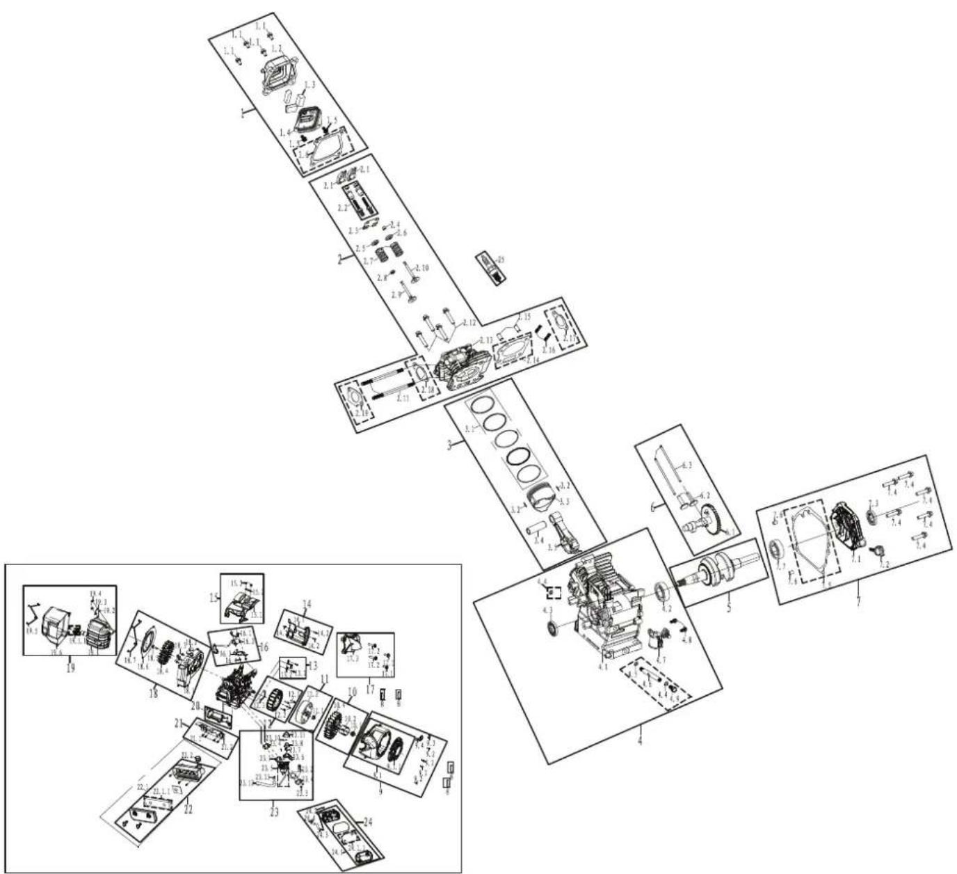
ENGINE PARTS LIST
| NO. PART # DESCRIPTION | |
| 1 50010026 CYLINDER HEAD COVER KIT ASSEMBLY | |
| 1.1 91325 BOLT M6X12 | |
| 1.2 24115 CYLINDER HEAD COVER | |
| 1.3 33995 POLYURETHANE SCREEN | |
| 1.4 24116 CYLINDER HEAD INTERNAL COVER | |
| 1.5 91322 BOLT M5*12 | |
| 1.6 96200 CYLINDER HEAD COVER GASKET | |
| 2 50020056 CYLINDER HEAD KIT ASSEMBLY | |
| 2.1 242101 ROCKING ARM | |
| 2.2 91818 ROCKING ARM WITH TIGHT BOLT ASSEMBLY | |
| 2.3 242202 VALVE RETAINER ASSEMBLY | |
| 2.4 241804 TOP CAP | |
| 2.5 241801 INTAKE VALVE SPRING SEAT | |
| 2.6 241802 EXHAUST VALVE SPRING SEAT | |
| 2.7 246001 VALVE SPRING | |
| 2.8 241806 INTAKE VALVE SPRING LOWER SEAT | |
| 2.9 241704 INTAKE VALVE | |
| 2.10 245904 EXHAUST VALVE | |
| 2.11 91029 AIR INLET STUD BOLT | |
| 2.12 91359 BOLT M8*60 | |
| 2.13 241021 CYLINDER HEAD | |
| 2.14 96058 CYLINDER HEAD GASKET | |
| 2.15 240905 CYLINDER HEAD LOCATING PIN | |
| 2.16 91007 AIR EXHAUST STUD BOLT | |
| 2.17 96055 EXHAUST GASKET | |
| 2.18 96182 INTAKE GASKET | |
| 2.19 96051 CARBURETOR GASKET | |
| 3 50050018 PISTON & PISTON RING KIT ASSEMBLY | |
| 3.1 241607 PISTON RING ASSEMBLY | |
| 3.2 241301 PISTON PIN RING | |
| 3.3 24121 PISTON | |
| 3.4 245503 PISTON PIN | |
| 3.5 331500 CONNECTING ROD ASSEMBLY | |
| 4 50120050 CRANKCASE KIT ASSEMBLY | |
| 4.1 330202 CRANKCASE | |
| 4.2 93010 BEARING | |
| 4.3 93507 CRANKCASE OIL SEAL | |
| 4.4 94007 OIL DRAIN BOLT WASHER | |
| 4.5 94035 OIL DRAIN BOLT WASHER | |
| 4.6 91831 OIL DRAIN SOLENOID | |
| 4.7 24513 OIL SENSOR | |
| 4.8 91329 BOLT M6X16 | |
| 4.9 91816 OIL DRAIN BOLT | |
| 5 240364 CRANKSHAFT ASSEMBLY | |
| 6 50150005 CAMSHAFT ASSEMBLY | |
| 6.1 332003 CAMSHAFT ASSEMBLY | |
| NO. PART # DESCRIPTION | ||
| 6.2 24610 | 3 VALVE LIFTER | |
| 6.3 24190 | 1 PUSH ROD | |
| 7 502000 | 52 CRANKCASE | COVER KIT ASSEMBLY |
| 7.1 24011 | 6 CRANKCASE | COVER |
| 7.2 24560 | 1-295 DIPSTIC | K ASSEMBLY |
| 7.3 93507 | CRANKCASE | OIL SEAL |
| 7.4 91347 | BOLT M8X30 | |
| 7.5 96041 | CRANKCASE | GASKET |
| 7.6 24090 | 4 CRANKCASE | LOCATING PIN |
| 7.7 93010 | BEARING | |
| 8 599601 | METAL CLIP | |
| 9 500900 | 53 RECOIL STARTER | KIT ASSEMBLY |
| 9.1 33050 | 1 RECOIL STARTER ASSEMBLY | |
| 9.1.1 5324 | START PULLER RECOIL COVER | |
| 9.2 91329 | BOLT M6X16 | |
| 9.3 50001 | 7-231 RECOIL HANDLE COVER | |
| 9.4 50001 | 8 RECOIL HANDLE | |
| 10 50170 | 007 IMPELLER | KIT ASSEMBLY |
| 10.1 9186 | 4 STARTER PULLEY COMPRESSION BOLT | |
| 10.2 3345 | 01 STARTER PULLEY | |
| 10.3 3346 | 01 IMPELLER | |
| 11 50760 | 003 ROTOR KIT | ASSEMBLY |
| 11.1 9000 | 3 NUT M14 | |
| 11.2 5036 | 98 ROTOR | |
| 12 50750 | 002 STATOR KIT ASSEMBLY | |
| 12.1 9140 | 0 BOLT M6X60 | |
| 12.2 5034 | 10 STATOR | |
| 12.3 2409 | 04 CRANKCASE | LOCATING PIN |
| 13 50740 | 002 TRIGGER KIT ASSEMBLY | |
| 13.1 9132 | 9 BOLT M6X16 | |
| 13.2 3399 | 02 TRIGGER | |
| 14 50130 | 012 WIND-LEAD-COVER KIT ASSEMBLY | |
| 14.1 3305 | 03 WIND-LEAD-COVER | |
| 14.2 9132 | 5 BOLT M6X12 | |
| 15 50620 | 001 UPPER WIN | NDFLECTOR KIT ASSEMBLY |
| 15.1 3305 | 02 UPPER WIN | D DEFLECTOR |
| 15.2 2499 | 14 CRIMPING BLOCK | |
| 15.3 9132 | 5 BOLT M6X12 | |
| 16 50340 | 004 IGNITION COIL KIT ASSEMBLY | |
| 16.1 9133 | 3 BOLT M6*28 | |
| 16.2 3399 | 09 IGNITION COIL | |
| 16.3 3399 | 03 HIGH-VOLTAGE PACKAGE MOUNTING BRACKET | |
| 16.4 9001 | 6 NUT M6 | |
| 17 50770 | 001 PANEL KIT | ASSEMBLY |
| 17.1 9132 | 9 BOLT M6X16 | |
ENGINE PARTS LIST CONTINUED
| NO. PART # DESCRIPTION | ||
| 17.2 91330 BOLT M6X20 | ||
| 17.3 335701 PANEL | ||
| 18 50630001 CENTRIFUG | GAL FAN HOUSING KIT ASSEMBLY | |
| 18.1 244306 CENTRIFUG | GAL FAN HOUSING | |
| 18.2 244304 CENTRIFUG | GAL FAN PLUG | |
| 18.3 91343 BOLT M8*16 | ||
| 18.4 244606 IMPELLER | ||
| 18.5 91419 BOLT M8*1*25 | ||
| 18.6 334302 CENTRIFUG | GAL FAN COVER | |
| 18.7 91330 BOLT M6X20 | ||
| 19 50240020 EXHAUST | MUFFLER KIT ASSEMBLY | |
| 19.1 243782 MUFFLER | ||
| 19.1.1 6790 SPARK ARPESTER | ||
| 19.2 94216 FLAT WASHER | ||
| 19.3 94206 SPRING WASHER | ||
| 19.4 90011 NUT M8 | ||
| 19.5 91330 BOLT M6X20 | ||
| 19.6 500057 MUFFLER | COVER | |
| 20 240511 SHIELD | ||
| 21 50630002 BRACKET | KIT ASSEMBLY | |
| 21.1 91330 BOLT M6X20 | ||
| 21.2 249917 BRACKET | ||
| 22 50030050 AIR FILTER | KIT ASSEMBLY | |
| 22.1 332901 AIR FILTER | ASSEMBLY | |
| 22.1.1 5691 AIR FILTER | ||
| 22.2 95918 CONNECTING PIPE | ||
| 23 50040104 CARBURETOR KIT ASSEMBLY | ||
| 23.1 332301 CARBURETOR CONNECTION BLOCK | ||
| 23.2 339905 BRACKET | ASSEMBLY | |
| 23.3 90016 NUT M6 | ||
| 23.4 94229 AIR FILTER | GASKET | |
| 23.5 332808 CARBURETOR ASSEMBLY | ||
| 23.6 249915 STEPPER | MOTOR BRACKET | |
| 23.7 92055 CROSS SCREW | STUD M4X25 | |
| 23.8 249949 STEPPER | MOTOR | |
| 23.9 249916 STEPPER | MOTOR PROTECTIVE COVER | |
| 23.10 92240 CROSS SCREW | STUD M4X6 | |
| 24 50630003 RESONANT | CAVITY KIT ASSEMBLY | |
| 24.1 337001 RESONANT | CAVITY ASSEMBLY | |
| 24.1.1 5697 FOAM FILTER | ||
| 24.2 249919 PLUG | ||
| 24.3 95602 BREATHER | TUBE | |
| 24.4 94407 FUEL LINE | CLAMP | |
| 25 97109 SPARK PLUG | ||
GENERATOR EXPLODED VIEW
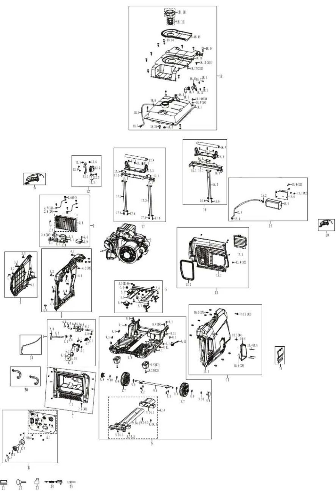
GENERATOR PARTS LIST
| NO. PART # DESCRIPTION | ||
| 1 1148225 | 110047 ENGINE ASSEMBLY DH225 | |
| 2 1001000 | 10 INVERTER KIT ASSEMBLY | |
| 2.1 91325 | BOLT M6X12 | |
| 2.2 503147 | INVERTER MOD JLE | |
| 2.3 503013 | BRACKET | |
| 2.4 91322 | BOLT M5X12 | |
| 2.5 599601 | METAL CLIP | |
| 2.6 91325 | BOLT M6X12 | |
| 2.7 500044 | SHORT WIRE | |
| 2.8 94003 | TOOTH WASHER | |
| 2.9 500700 | DC VOLTAGE REGULATOR | |
| 3 1001500 | 12 LEFT PANEL KIT ASSEMBLY | |
| 3.1 503039 | -221D LEFT PANEL | |
| 3.2 92097 | SCREW M6X20 | |
| 3.3 92079 | STOP BOLT M6X16 | |
| 4 1002800 | 15 LEFT FRAME KIT ASSEMBLY | |
| 4.1 503005 | -221 LEFT FRAME | |
| 4.2 91345 | BOLT M8X20 | |
| 4.3 500060 | LOCK CLIP M6 | |
| 4.4 92097 | SCREW M6X20 | |
| 4.5 500007 | FUEL TANK ISOLATION PAD A | |
| 5 1003800 | 01 BRACKET KIT ASSEMBLY | |
| 5.1 503001 | BRACKET | |
| 5.2 503002 | BRACKET | |
| 5.3 503003 | BRACKET | |
| 5.4 503004 | ISOLATION PAD | |
| 5.5 90044 | NUT M8 | |
| 5.6 91348 | BOLT M8X35 | |
| 6 1003800 | 07 BRACKET KIT ASSEMBLY | |
| 6.1 91325 | BOLT M6X12 | |
| 6.2 503017 | BRACKET | |
| 6.3 503772 | FUEL LINE 4X 10X 6X 12-89L | |
| 6.4 503773 | FUEL LINE 4X 10X 6X 12-45L | |
| 6.5 503020 | L FUEL LINE 4X 10-194L | |
| 6.6 503044 | CLIP | |
| 6.7 503062 | FUEL SWITCH | |
| 6.8 503034 | FUEL LINE CLAMP | |
| 6.9 516401 | FILTER | |
| 6.10 50024 | CABLE TRAY | |
| 6.11 500011 | FUEL SWITCH HOLDER | |
| 6.12 500003 | STEEL BALL | |
| 6.13 500012 | SPRING | |
| 7 1001400 | 02 PANEL REAR COVER KIT ASSEMBLY | |
| 7.1 503016 | PANEL REAR COVER | |
| 7.2 92078 | SCREW M6X16 | |
| 8 1001100 | 16 PANEL KIT ASSEMBLY | |
| NO. PART # DESCRIPTION | ||
| 8.1 50380 | 4 PANEL ASSEMBLY | |
| 8.1.1 | 9224 | ECO SWITCH |
| 8.1.2 | 9079 | WATERPROOF CAP |
| 8.1.3 | 9230 | VOLTAGE RESET SWITCH |
| 8.1.4 | 9227-31 | THERMAL PROTECTOR |
| 8.1.5 | 6404 | WATERPROOF CAP |
| 8.1.6 | 9227-30 | THERMAL PROTECTOR |
| 8.1.7 | 6404 | WATERPROOF CAP |
| 8.1.8 | 9229 | USB |
| 8.1.9 | 503108 USB DUST COVER | |
| 8.1.10 | 9227-20 | THERMAL PROTECTOR |
| 8.1.11 | 6404 | WATERPROOF CAP |
| 8.1.12 | 9228 | IGNITER |
| 8.1.13 | 9236 | CO WARNING LIGHT |
| 8.1.14 | 9236 | CO WARNING LIGHT |
| 8.1.15 | 9235 | LED |
| 8.1.16 | 9232 | PARALLEL SOCKET |
| 8.1.17 | 9122 | WATERPROOF COVER |
| 8.1.18 | 9132 | GROUNDING BOLT |
| 8.1.19 | 6032 | L5-20R RECEPTACLE |
| 8.1.20 | 9194 | DUST COVER |
| 8.1.21 | 6015 | RV SOCKET |
| 8.1.22 | 6849 | DUST COVER |
| 8.2 91825 | SCREW & FLAT WASHER M5X12 | |
| 8.3 50302 | 4 KNOB | |
| 8.4 50006 | 8 HANDLE PANEL PLUG | |
| 8.5 92032 | SCREW M4X16 | |
| 8.6 94325 | FLAT WASHER 4 | |
| 8.7 50331 | 0 KNOB PLUG | |
| 9 100200 | 06 BASEBOARD KIT ASSEMBLY | |
| 9.1 90027 | SQUARE NUT | |
| 9.2 91325 | BOLT M6X12 | |
| 9.3 50304 | 5 BOTTOM PLATE | |
| 9.4 50006 | 0 LOCK CLIP M6 | |
| 9.5 50302 | 6 ISOLATION PAD | |
| 9.6 50302 | 3 AXLE | |
| 9.7 50303 | 1 WHEEL | |
| 9.8 50303 | 2 WHEEL COVER | |
| 9.9 94022 | STEEL WASHER | |
| 9.10 5003 | 21 AXLE WILD CARD | |
| 9.11 5030 | 53 LIMIT BLOCK | |
| 9.12 5030 | 52 BASE OIL COVER | |
| 9.13 9133 | 4 BOLT M6X30 | |
| 9.14 1003 | 10003 PULL ROD KIT ASSEMBLY | |
| 9.14.1 | 503033 PULL ROD SEAT | |
| 9.14.2 | 503035 PULL ROD | |
| 9.14.3 | 91334 BOLT M6X30 | |
GENERATOR PARTS LIST CONTINUED
| NO. PART # DESCRIPTION | |
| 10 100280022 RIGHT FRAME | KIT ASSEMBLY |
| 10.1 503021-221D RIGHT FRAME | |
| 10.2 91345 BOLT M8X20 | |
| 10.3 500060 LOCK CLIP M6 | |
| 10.4 503067 BLIND RIVET | |
| 10.5 503036-052 HANDLE | DECORATIVE BOARD |
| 10.6 94249 FLAT WASHER | |
| 10.7 92097 SCREW M6X20 | |
| 11 503022-221 OBSERVATION | COVER |
| 12 100450001 CO MODULE | KIT ASSEMBLY |
| 12.1 503807 CO MODULE | BRACKET |
| 12.2 599070 CO MODULE | |
| 12.3 599071 CO FLAMEOUT | ACTUATOR |
| 12.4 92328 BOLT M4*12 | |
| 12.5 91325 BOLT M6X12 | |
| 12.6 90016 NUT M6 | |
| 13 100030002 MUFFLER PANEL KIT ASSEMBLY | |
| 13.1 503027 MUFFLER PANEL | |
| 13.2 500108 MUFFLER EXHAUST SEALING STRIP | |
| 13.3 503040 COVER | |
| 13.4 92078 SCREW M6X16 | |
| 14 500333 CABLE | |
| 15 102200004 CARBON CANISTER KIT ASSEMBLY | |
| 15.1 91325 BOLT M6X12 | |
| 15.2 94405 FUEL LINE CLAMP 11.5 | |
| 15.3 94403 FUEL LINE CLAMP 11.5 | |
| 15.4 91334 BOLT M6X30 | |
| 15.5 543301L CARBON CANISTER ASSEMBLY | |
| 15.6 503043 BRACKET | |
| 15.7 95016 CARBON CANISTER AND AIR FILTER CONNECTING PIPE | |
| 16 100380003 BRACKET KIT ASSEMBLY | |
| 16.1 91325 BOLT M6X12 | |
| 16.2 503006 LIFTER | |
| 16.3 503008 BRACKET | |
| 16.4 503009 HANDLE | |
| 16.5 503042 BRACKET | |
| 16.6 91330 BOLT M6X20 | |
| 17 100380007 BRACKET KIT ASSEMBLY | |
| 17.1 91325 BOLT M6X12 | |
| 17.2 503007 LIFTER | |
| 17.3 503008 BRACKET | |
| 17.4 503009 HANDLE | |
| 17.5 503011 BRACKET | |
| 17.6 91330 BOLT M6X20 | |
| 18 100070008 FUEL TANK KIT ASSEMBLY | |
| NO. PART # DESCRIPTION | ||
| 18.1 5037 | 75 FUEL TANK ASSEMBLY | |
| 18.2 5000 | 08 FUEL TANK ISOLATION PAD | |
| 18.3 9132 | 2 BOLT M5X12 | |
| 18.4 5002 | 52 SEALING RING | |
| 18.5 9512 | 7 CARBON CANISTER AND FUEL TANK CONNECTING PIPE | |
| 18.6 5002 | 47 GASOLINE SENSOR | |
| 18.7 9440 | 5 FUEL LINE CLAMP 11.5 | |
| 18.8 9440 | 3 FUEL LINE CLAMP 11.5 | |
| 18.9 9680 | 1 FUEL TANK GASKET | |
| 18.10 913 | 97 BOLT M6X20 | |
| 18.11 | 500244 PRESS PLATE | |
| 18.12 500 | 324 SEALING WASHER | |
| 18.13 500 | 068 HANDLE PANEL PLUG | |
| 18.14 503 | 025 PLUG | |
| 18.15 503 | 029 FUEL SLOT | |
| 18.16 503 | 038-221 TOP COVER | |
| 18.17 920 | 78 SCREW M6X16 | |
| 18.18 503 | 028 FUEL CAP | |
| 18.19 518 | 801 FUEL TANK FILTER | |
| 18.20 503 | 782 FUEL NOZZLE | |
| 19 50381 | 2 DEPUTY WIRING HARNESS | |
| 20 50308 | 2 BELLOWS | |
| 21 99011 | SPARK PLUG SLEEVE | |
| 22 50094 | 2 FUNNEL | |
| 23 99629 | OIL BOTTLE ASSEMBLY | |
| 24 50380 | 6 DEPUTY WIRING HARNESS | |
| 25 99506 | DUAL - PURPOSE SCREWDRIVER | |
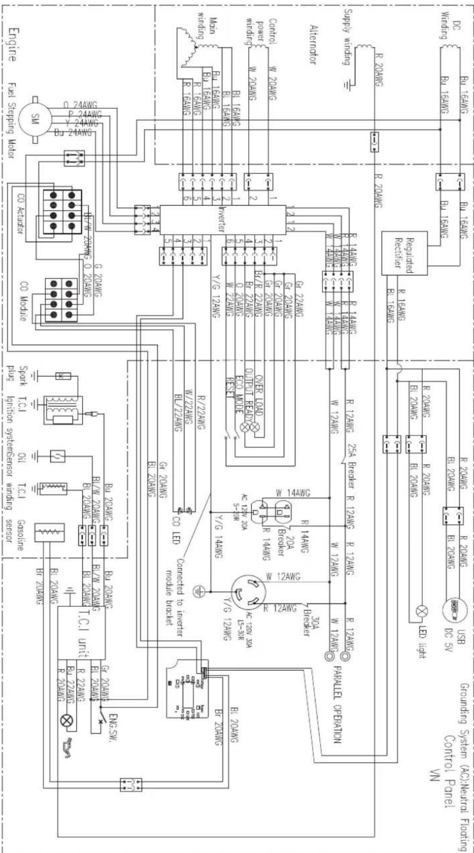
SCHEMATICS
SCHEMATICS
| Y | Yellow | BL/W | Black/white | Bul/W | Blue white |
| W | White | P | Pink | Pu | Purple |
| Bu | Blue | Cr | Gray | O | Orange |
| R | Red | Br/R | Brown/red | Y | Yellow |
| Bl | Black | Br | Brown | Y/G | Yellow green |
iGen4500cv
Generador Inversor Digital
Westinghouse Outdoor Power
Warranty registration
777 Manor Park Drive
Columbus, OH 43228
Para su archivo


WARNING | PELIGRO | ATTENTION

Operate, store, and transport on firm level surface. Do not rest on exhaust panel. Tilting can cause fuel spillage
Using a generator indoors CAN KILL YOU IN MINUTES. Generator exhaust contains carbon monoxide. This is a poisson you can not see or smet


[Unreadable]
puesia
-806.19
EN EXT
y(θ)36 0
da venti
WARNING: Cancer and reproductive harm www.P68Warnings.ca.gov/product AVERTISSEMENT: Cancer et problèmes de reproduction - www.P68Warnings.ca.gov/product ADVERTENCIA: Cancer y danes al sistema reproduct - www.P68Warnings.ca.gov/product.

ACTION LABEL

AUTOMATIC SHUTOFF - YOU MUST: ETIQUETA DE FUNCIONAMIENTO: ETIQUETTE D'ACTION:


- MOVE GENERATOR TO AN OPEN, OUTDOOR AREA. - POINT EXHAUST AWAY. - DON'T RUN GENERATOR IN ENCLOSED AREAS E.G. NOT IN HOUSE OR GARAGE, - NOVE EL GENERADOR A UN AREA ABIERTA, EN EXTERBORES - ORIENTAR EL TUBO DE ESCAPE HACIA AFUERA - NO ACTIVAR EL GENERADOR EN AREAS CERRADAS (P.E.I.: EN UNA CASA O GARAJE) - DEPLACER LA GENERATRICE DANS UN ASPACE EXTERIEUR OUVERT - DRUGER L'EXCHAPPEMENT LOIN DE VOUS - NE PAS FAIRE FONCTIONNER LA GENERATRICE DANS DES ENDORTS FERNES SPRINGE LEASE LA MAJENUE GUEZ CHARGA

• MOVE TO FRESH AIR. • GET MEDICAL HELP IF SICK, DIZZY OR WEAK. • MOVER AL AIRE LIBRE • OBTENER ATENCION MEDICA SI SE SIENTE ENFERMO, MAREADO O DEBIL • VOUS RETIRER A L'AIR FRAIS • CONSULTER UN MERCEIN SI VOUS ETES MALADE, ETOURDI OU FAIBLE
CONSULTER UN MEDECIN SI VOUS ETES MALADE, ETOURDI OU FAIBLE

natural_image
Line drawing of a portable electricity generator with a hand holding a screwdriver (no text or symbols)natural_image
Line drawing of a portable electricity generator with a hand using a screwdriver to adjust its power output (no text or symbols visible)46 | Westinghouse Outdoor Power Equipment, LLC
natural_image
Technical line drawing of a mechanical component with a magnified view showing a detail (no text or symbols)MANTENIMIENTO DEL FILTRO DE AIRE
ADVERTENCIA
natural_image
Technical line drawing of a vehicle chassis with labeled components and a close-up inset showing lock mechanism (no text or symbols present)natural_image
Line drawing of a portable electricity generator with a hand holding a screwdriver (no text or symbols present)natural_image
Technical line drawing of a vehicle rear view showing engine compartment and exhaust pipe (no text or symbols)Supresor de chispas
NE PAS RETOURNER CE PRODUIT AU MAGASIN
CENTRE DE DONNÉES LED 64
COMPOSANTS DU PANNEAU DE COMMANDE....65
ASSEMBLÉ
CONTENU DU CARTON 66
CARBURANT....67
REMLIR LE RÉSERVOIR DE CARBURANT ....67
OPÉRATION
EMPLACEMENT DU GÉNÉRATEUR....68
MISE À LA TERRE....68
FONCTIONNEMENT À HAUTE ALTITUDE....69
PÉRIODE DE RODAGE 69
AVANT DE DÉMARRER LE GÉNÉRATEUR ......69
DEMARRAGE DU MOTEUR 69
ARRÊT DU MOTEUR ....70
FRÉQUENCE D'UTILISATION ....70
MODE ECO 70
DISJONCTEUR AC....70
SURCHARGE RÉINITIALISER....70
CAPACITÉ DU GÉNÉRATEUR....71
GESTION DE L'ALIMENTATION 71
RALLONGES 72
DIMENSIONS DU CORDON D'EXTENSION....72
FONCTIONNEMENT PARALLÈLE 72
TRANSPORT 73
ENTRETIEN
CALENDRIER DE MAINTENANCE....74
PIÈCES DE RECHANGE D'ENTRETIEN 74
COUVERCLE DE SERVICE DU MOTEUR 74
MANTENIMIENTO DEL FILTRO DE AIRE....74
CONTRÔLE DU NIVEAU D'HUILE MOTEUR .... 75
CHANGEMENT D'HUILE MOTEUR 76
MAINTENANCE DES BOUGIES 76
SERVICE DE PARE-ÉTINCELLES....77
ESPACE DE RANGEMENT 77
LE JEU DES SOUPAPES 78
DÉPANNAGE
DÉPANNAGE....79
INTRODUCTION
Westinghouse Outdoor Power
Warranty registration
777 Manor Park Drive
Columbus, OH 43228
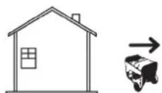
Failure to follow warnings, instructions and operator's manual will result in death or serious injury.

Generator could cause electrical shock.

• DO NOT operate in rain or wet weather.

Never fuel unit with engine running. Always fuel in well ventilated area. Always allow unit to cool before fusing.

Hot muffler and exhaust cases can cause fires. Keep at least

5ft (1.5m) clearance from any combustibles or structures,

Exhaust contains poisonous carbon monoxide gas that can cause unconsciousness or DEATH. Install Carbon Nanopexi

claims inside home.

For electrical equipment only. Failure to
property ground generator can result in electromotion.
PELIGRO

The Ground Truth image displays a single, solid horizontal line. According to Rule 2 (UNDERSCORE & LINE RULES), if the GT contains lines used for stylistic emphasis or as background elements (like ruled paper), the OCR result must ignore them. The OCR content provided is "____", which consists of four underscores. This is incorrect because underscores are not equivalent to a solid line and are not permitted under the “Stylistic/Background Lines (Ignore)” rule. The OCR has hallucinated underscores where none should exist in the GT, violating the rule to ignore stylistic lines. Therefore, the OCR result is inconsistent with the Ground Truth.

ATTENTION

SURFACES

CHAODES

Westinghouse
Westinghouse Outdoor Power Equipment, LLC Columbus Ohio 43228 USA
Westinghouse Outdoor Power Equipment, LLC Columbus Ohio 43228 USA
Model
Model
Part No
Nohera
4C Val
Tenska
AC CU
Intensit
Model
Model
Part No
Nohera
4C Val
Tenska
AC CU
Intensit
Model
Model
Part No
Model
Part No
Nohera
4C Val
Surface plane et
eau d'echappement.
ement de carburant.
evel surface.
can cause fuel
2016年1月29日
superficie firme
de escape
ne de combustible.
interface plane et
eau d'echappement
ement de carburant.


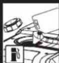
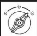


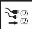
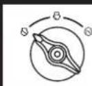

WARNING PELIGRO ATTENTION

Operate, store, and transport on firm level surface. Do not rest on exhaust panel. Tilting can cause fuel spillage
Using a generator indoors CAN KILL YOU IN MINUTES. Generator exhaust contains carbon monoxide. This is a poison you can not see or smell


windows, doors and vents.
PELIGRO
was in generator
ORIFA EL
OCOS MINUTOS.
cszapo cel
esercor os-Jenis orgado de
arbona. Es
neno cuo
CHINSE
orto ce u
- A
plan apied
Solo useko
N EXTERI
HCPA
vanduci

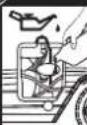
ACTION LABEL
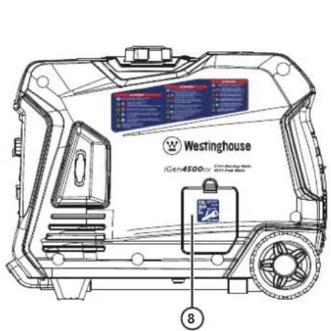
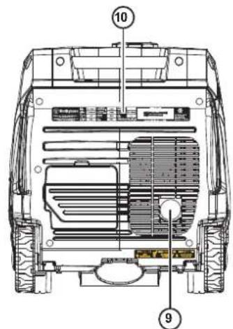
CENTRE DE DONNÉES LED
natural_image
Line drawing of a portable electricity generator with a hand holding a screwdriver (no text or symbols present)natural_image
Line drawing of a portable electricity generator with a hand holding a screwdriver, showing no text or symbols on the device itself.natural_image
Symmetrical abstract diagram with concentric circles and radial lines, enclosed in a circle (no text or symbols)ARRÊT DU MOTEUR
DIMENSIONS DU CORDON D'EXTENSION
natural_image
Technical line drawing of a mechanical component with a magnified view showing a cutaway section (no text or symbols)MANTENIMIENTO DEL FILTRO DE AIRE
⚠️ AVERTISSEMENT
natural_image
Line drawing of a portable electricity generator with a hand holding a screwdriver (no text or symbols present)natural_image
Technical line drawing of a vehicle rear view showing engine, battery, and sensor components (no text or labels)Supresor de chispas
Couple: 106 inch-pound (12 N·m)
WestinghousePortablePower.com
Service Hotline: (855) 944-3571
777 Manor Park Drive
Columbus, OH 43228
^TM & © 2020 Westinghouse Electric Corporation
© 2020 Westinghouse Outdoor Power Equipment, LLC All Rights Reserved.
iGen4500cv Rev01
122034 Rev02 12/21