
STI70ASPI - Cooker SIGNATURE - Free user manual and instructions
Find the device manual for free STI70ASPI SIGNATURE in PDF.

| Product type | Induction hob with integrated extractor |
| Brand | Signature |
| Model | STI70ASPI |
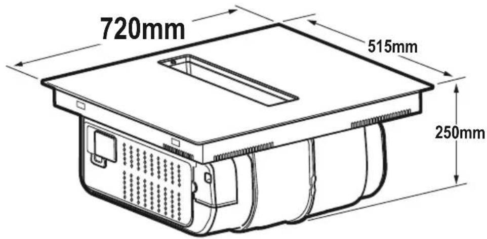
| Dimensions (L x D x H) | 70 x 51 x 6 cm (approx) |
| Weight | Approx. 12 kg |
| Power supply | 220-240 V ~ 50/60 Hz, max 7.4 kW |
| Installation type | Built-in |
| Cooking power | 9 levels + Boost (P) |
| Extraction power | 4 levels + Boost |
| Main functions | Induction, integrated extractor, Boost, Timer, Pause, Key Lock, Bridge, Temperature Manager, Automatic Heat Up, Power Limitation, Egg Timer, Automatic extractor function |
| Cooking zones | 4 zones (FL, RL, FR, RR) with Bridge function |
| Pan detection | Yes (Pot Detector) |
| Safety shut-off | Yes (Safety Shut Down) |
| Residual heat indicator | Yes (H symbol) |
| Extraction type | Extraction version (external venting) or recirculation version (internal recycling) |
| Filters | Metal grease filter (washable), activated carbon filter (regenerable) |
| Hob maintenance | Clean after each use with a soft cloth and specific product; do not use abrasives or steam cleaner |
| Extractor maintenance | Damp cloth with mild detergent; clean the recovery tray if overflow |
| Safety | Child lock (Key Lock), Pause, automatic shut-off, pan detection, residual heat indicator |
| Spare parts | Grease and carbon filters available at specialized retailers |
| Repairability | Contact customer service; do not repair yourself |
| Warranty | Legal conformity warranty 2 years |
Frequently Asked Questions - STI70ASPI SIGNATURE
User questions about STI70ASPI SIGNATURE
0 question about this device. Answer the ones you know or ask your own.
Ask a new question about this device
Download the instructions for your Cooker in PDF format for free! Find your manual STI70ASPI - SIGNATURE and take your electronic device back in hand. On this page are published all the documents necessary for the use of your device. STI70ASPI by SIGNATURE.
USER MANUAL STI70ASPI SIGNATURE
natural_image
3D rendering of a black rectangular object with a vertical slot and diagonal line, no text or symbols visibleSIGN ≤ TURE ®
● Residual Heat Indicator
● Temperature, manager, (Warming Function)
● Automatic, Heat UP.
natural_image
Black rectangular object with a grid-like structure on top, no visible text or symbolsSIGN ≤ TURE ®
INDUCTION HOB
STI70ASPI
INDEX
INTRODUCTION 38
SAEETY AND REGULATIONS 39
USE 47
OPERATION 50
MAINTENANCE 66
ASSISTANCE 68
INTRODUCTION
Strictly observe the instructions in this manual. All liability is declined for any problems, damage or fires caused by failure to comply with the instructions in this manual. The device is intended for domestic use only, to cook food and extract the fumes generated by cooking. No other use is allowed (e.g. heating rooms). The manufacturer declines any liability for inappropriate use or incorrect control settings. The device may have different aesthetic features with respect to the illustrations in this handbook, however the operating, maintenance and installation instructions remain the same.
● Read the instructions carefully: they contain important information on installation, operation and safety.
- Do not make electrical changes to the device.
- Before installing the device, make sure that none of the components are damaged. Otherwise, contact the dealer and do not continue with the installation.
- Check that the device is intact before proceeding with installation. Otherwise, contact the dealer and do not continue with the installation.
the parts marked with this symbol can be purchased separately from specialised dealers.
SAFETY AND REGULATIONS
GENERAL SAFETY
Please note! Pay strict attention to the following instructions:
● The device must be disconnected from the mains before carrying out any installation work. ● For all installation and maintenance operations, always use work gloves. ● Installation or maintenance must be performed by a qualified technician, in compliance with the manufacturer's instructions and local safety regulations. ● Only use the fastening screws supplied with the product for installation, or if not supplied, purchase the correct type of screws. ● Use screws of the right length, as indicated in the installation guide. ● Do not repair or replace any part of the product unless specifically stated in the operating manual. ● Ensure that children do not play with the product; keep children at a safe distance and supervise them as the accessible parts may become very hot during use. ● The product can be used by children over the age of 8 and by people with reduced physical sensory or mental capabilities or without experience or the necessary knowledge, as long as they are properly supervised or have been instructed on how to safely use the product and understand the inherent dangers. ● The product and its accessible parts get hot during use. Be careful not to touch the heating elements. ● Do not touch the heating elements of the product during and after use. ● Avoid contact with kitchen towels or other flammable materials until all components of the product have sufficiently cooled, fire hazard. ● Do not place flammable materials on or near the product. ● Overheated fats and oils easily catch fire. ● Unattended cooking on a hob with oil or fat can be dangerous and may cause a fire. ● Extra care must be taken when frying to prevent the oil from overheating and
catching fire. ● The cooking process must be supervised. A short cooking process must be constantly monitored. ● NEVER attempt to put fires out using water. Instead, turn off the product and smother the flames, for example with a lid or a fire blanket. ● Prevent liquids from boiling over, therefore turn the heat down when boiling or heating liquids. ● Do not leave the heating elements turned on with empty pots and pans, or without any cookware. ● Never heat a tin or can containing foods without opening it first: it might explode! This warning also applies to all other types of hops. ● Switch off the relevant cooking zone when you have finished cooking. ● The product is not intended to be operated with an external timer or a separate remote control system. Do not use steam cleaners, risk of electric shock. ● Before doing any cleaning or maintenance work, disconnect the product from the mains by disconnecting the plug or turning off the mains switch. ● Cleaning and maintenance must never be performed by children unless they are properly supervised. ● The product must be cleaned frequently both inside and out (AT LEAST ONCE A MONTH): always follow the instructions given in the maintenance manual. ● This manual must be stored for future consultation at any time. If sold, transferred or moved, it must remain with the product.
- Range hoods and other cooking fume extractors may adversely affect the safe operation of appliances burning gas or other fuels (including those in other rooms) due to back flow of combustion gases. These gases can potentially result in carbon monoxide poisoning. After installation of a range hood or other cooking fume extractor, the operation of flued gas appliances should be tested by a competent person to ensure that back flow of combustion gases does not occur.
- For people with pacemakers and active implants, it is important to check, prior to using the induction hob, that their pacemaker is compatible, with the product. ● If the surface is cracked, switch off the item to avoid the possibility of electric shock ● Risk of fire: do not place objects on, the cooking surfaces. ● Do not place metal objects, such as knives, forks, spoons or lids on, the hob because they could become hot. ● Important: ● After use, turn off, the hob using its control device and do not rely on the pot detector. ● Never use aluminium foil for cooking and never place products packaged in aluminium directly on the hob. The aluminium would melt and irreparably damage your product. ● High power levels such as the Booster function should not be used to heat certain liquids, such as oil for trying. Excessive heat may be dangerous. In these cases, we recommend the use of a lower power level. ● The cookware must be placed directly on the hob and must be centred. Under no circumstances may any other objects be placed between the pot and the hob. ● If the temperature becomes high, the product automatically decreases the power level of the cooking zones. ● Please note! The accessible parts of the device may become hot when the hob is switched on. ● Failure to comply with the rules for product cleaning and the cleaning/replacement of filters, may create a fire hazard. ● Flambe cooking is strictly prohibited. ● Using a naked flame may damage the filters and cause a fire hazard, and must therefore be avoided under all circumstances. ● The room must be sufficiently ventilated when the product is used at the same time as other appliances that run on gas or other fuels. ● The regulations laid down by local authorities must be strictly followed with regard to the technical and safety measures to be adopted for fume extraction. ● The extracted air must not be conveyed through the
same ducts used to extract the fumes generated by the combustion of gas or other types of fuels. ● Never use the product without the grille properly installed!
ELECTRICAL CONNECTION SAFETY
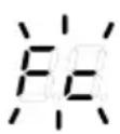
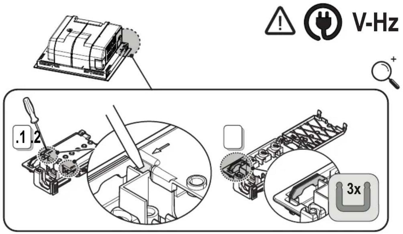
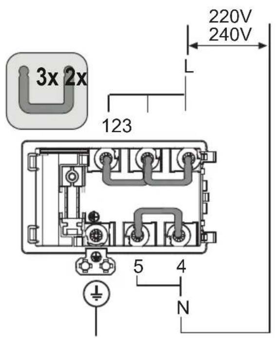
- Disconnect the product from the mains. ● Installation must be carried out by professionally qualified personnel with knowledge of the regulations in force for installation and safety. ● The manufacturer denies all liability to persons, animals or property if the guidelines provided in this chapter are not followed. ● By law, the product must be earthed. ● The power cable must be long enough to allow the product, built into the cabinet, to be connected to the mains. ● The power cable must be long enough to allow removal of the hob from the worktop. ● Do not use power strips or extension cords. ● Check that the voltage on the rating plate on the bottom of the product corresponds to that of the domestic environment where it will be installed. ● The earth cable must be 2cm longer than the other cables. ● The temperature must not reach 50°C above room temperature anywhere along the cable. ● The product is designed to be permanently connected to the mains; for this reason, make the connection to the mains via an omnipolar switch in accordance with the installation rules, which ensures complete disconnection from the mains in overvoltage category III conditions, and which is easily accessible after maintenance. ● Once installation is complete, the electrical components must no longer be accessible by the user. ● Please note! Do not connect the product to the mains until the installation is complete. ● Before connecting the product to the mains: check the rating plate (on the bottom of the product) to ensure that the voltage and power correspond to the mains supply and that the power socket is suitable. If in doubt, consult a qualified electrician.
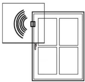
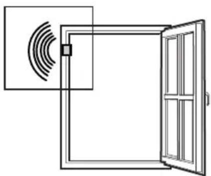
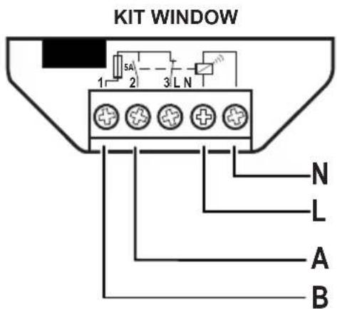
- If the product is not equipped with a power cable, use one with a minimum conductor section of 2.5 mm 2 for power up to 5500 Watt; while for higher powers it must be 4 mm 2 ). - Please note! The interconnection cable must be replaced by the authorised customer service representative or by a person with similar qualifications. - Please note! Before reconnecting the circuit to the mains power supply and making sure that it is working correctly, always check that the power cable is correctly installed. WINDOWS KIT: The product can also be used in conjunction with a Window sensor KIT (not supplied by the manufacturer). If the Window sensor KIT is installed (only if used in DUCT-OUT mode), air extraction will halt every time the window in the room, on which the KIT is applied, is closed. The KIT must be electrically connected to the device by qualified and specialised technical personnel. The KIT must be certified separately in accordance with the safety standards for the component and its use with the device. Installation must be carried out in accordance with current regulations for domestic systems. PLEASE NOTE: the wiring of the KIT to be connected to the product must be part of a certified safety extra-low voltage (SELV) circuit. The manufacturer of this device disclaims all liability for any inconvenience, damage or tires caused by defects and/or problems associated with the malfunction and/or incorrect installation of the KIT.
INSTALLATION SAFETY
● The electrical and mechanical installation must be performed by qualified personnel.
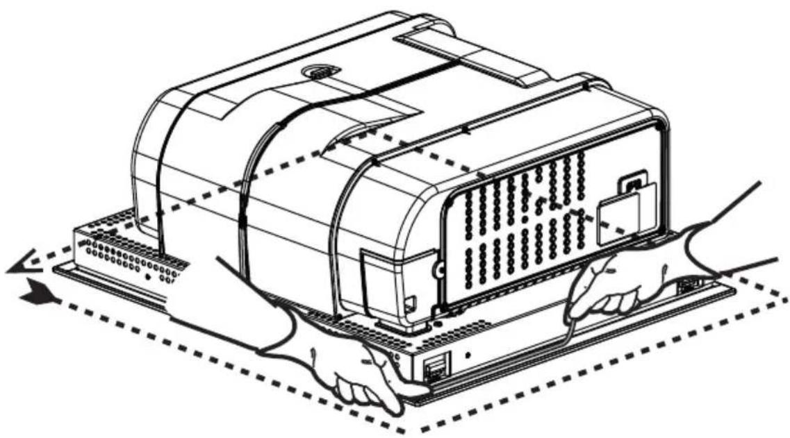
Before starting the installation: After unpacking the product, check that it has not been damaged during transport and in the case of problems, contact your dealer or Customer Service, before proceeding with the installation;
Check that the purchased product is the right size for the installation location; Check for accessories inside the packaging (placed there for ease of transport, such as bags containing screws, the warranty certificate, etc.). Remove and keep them safe; Also check that there is a power socket near the installation area.
● Preparing the cabinet for installation:
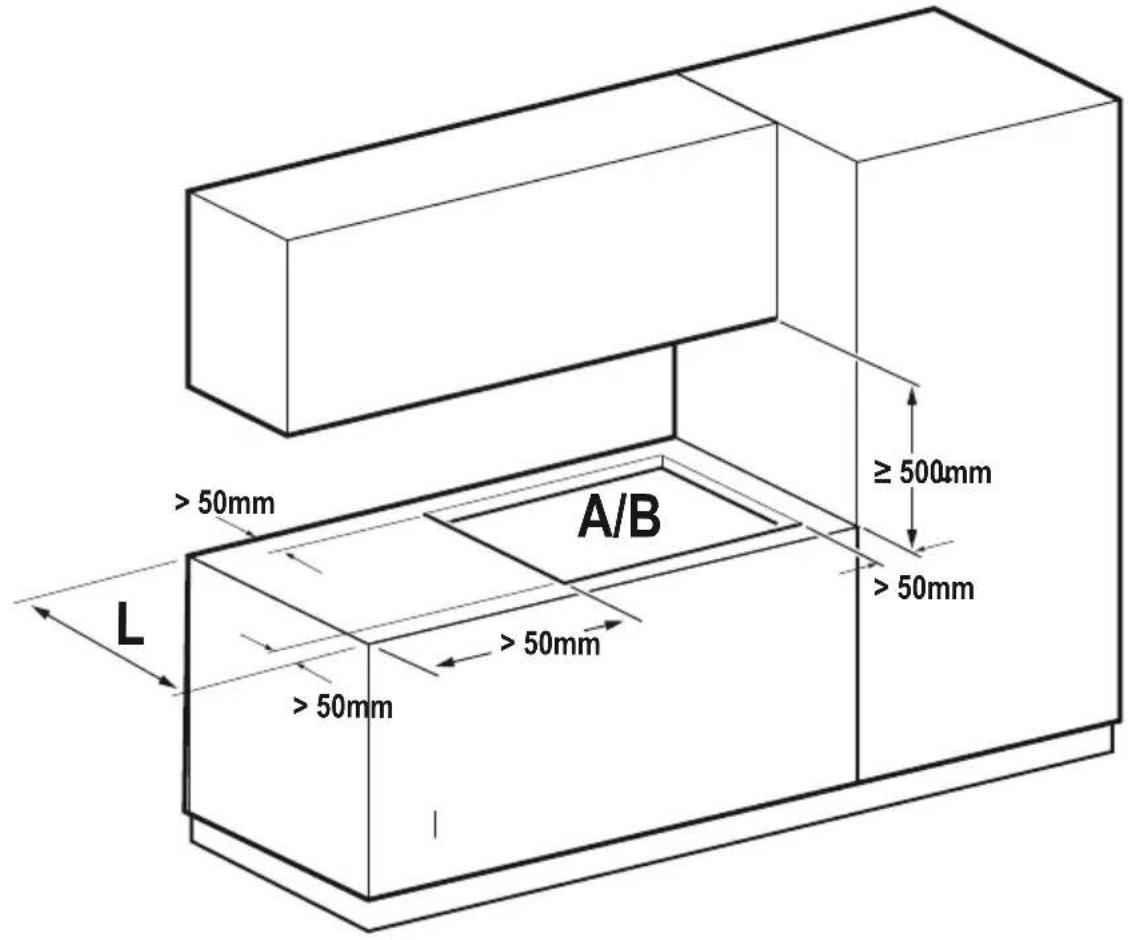
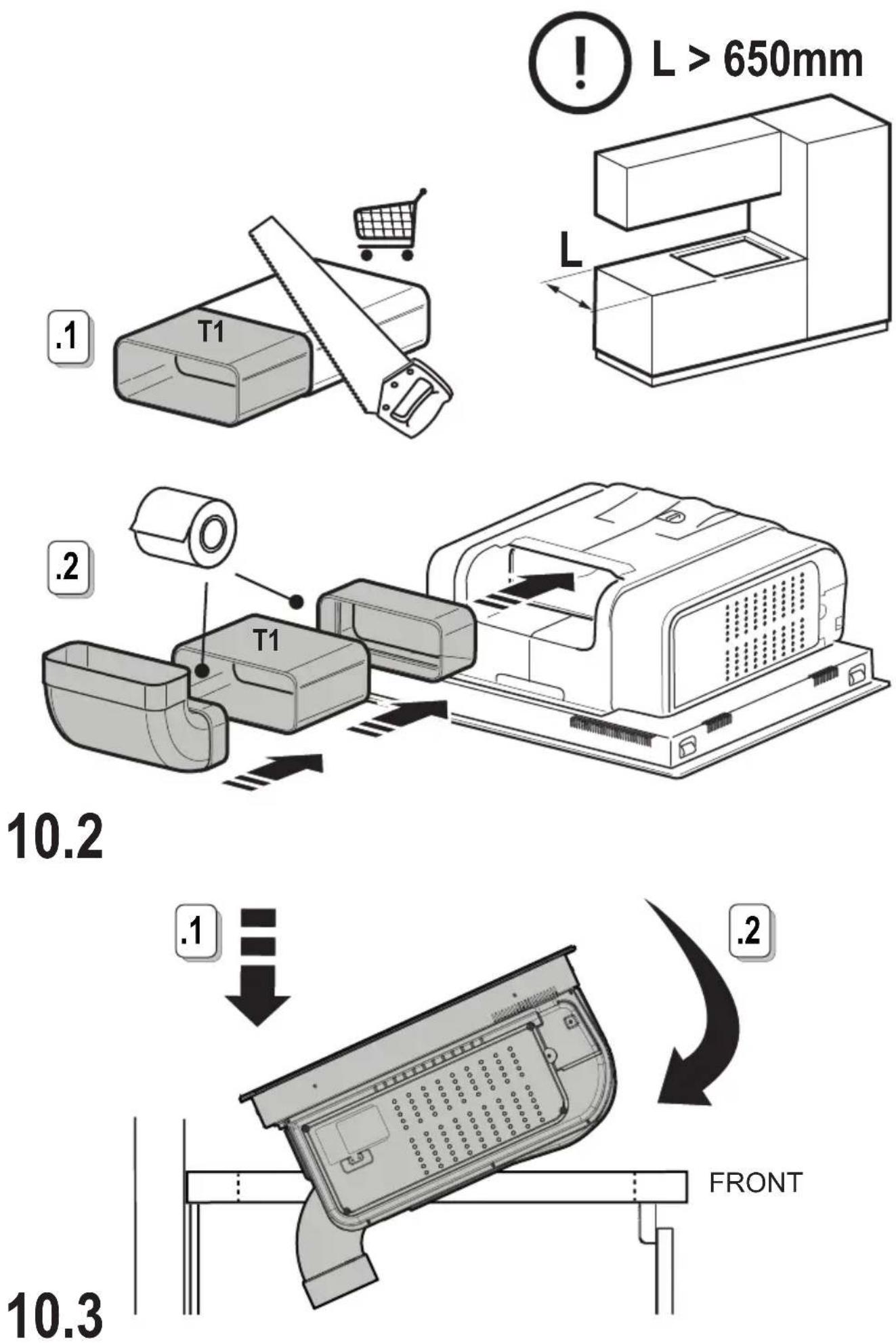
- The product cannot be installed above cooling appliances, dishwashers, heaters, ovens, washing machines and dryers. Create the cut-outs in the cabinet before inserting the hob and carefully remove shavings or sawdust.
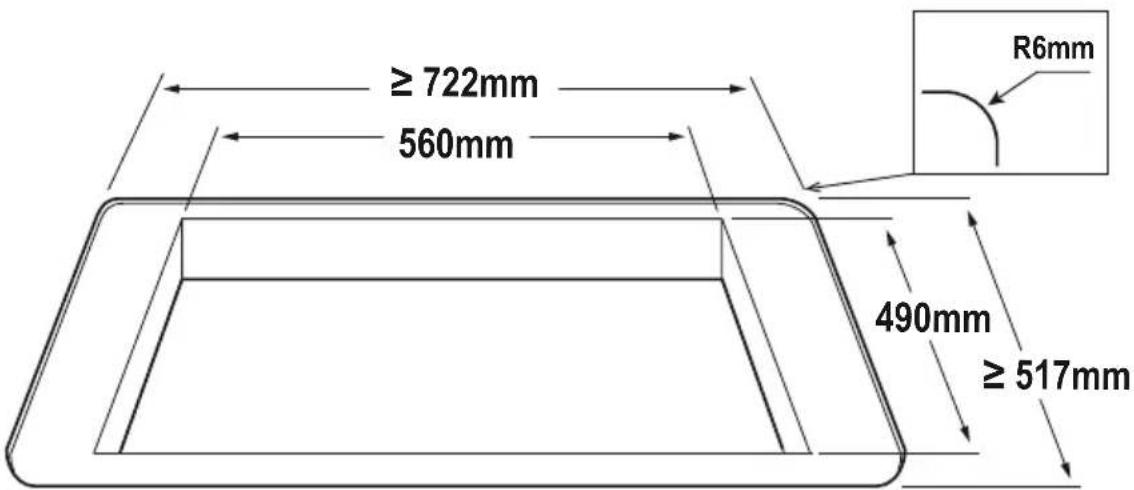
The minimum distance between the hob and the wall must be at least 50mm from the front, at least 50mm from the sides and at least 500mm from the upper wall units.
NB: when designing the space, the kitchen manufacturer's instructions must be followed...
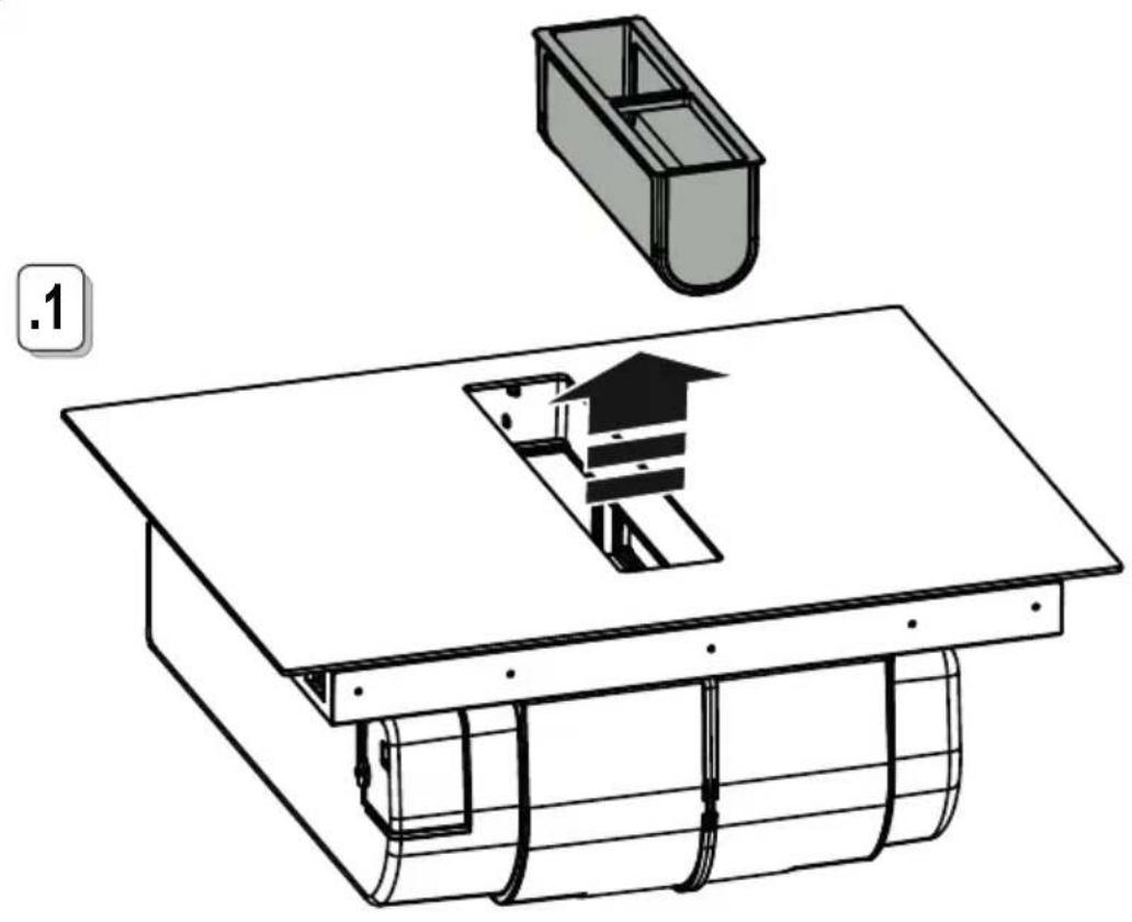
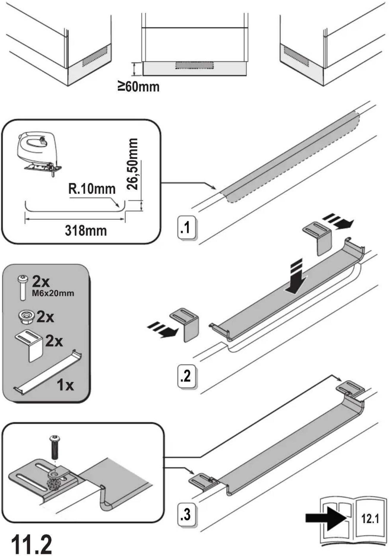
• to optimise the recirculating installation, it is recommended to create a slot in the plinth, in which to insert a commercial grille.
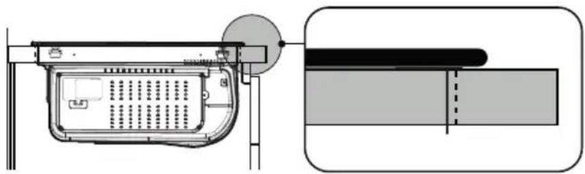
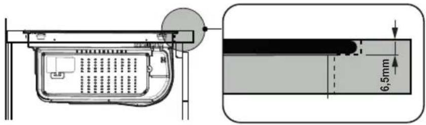
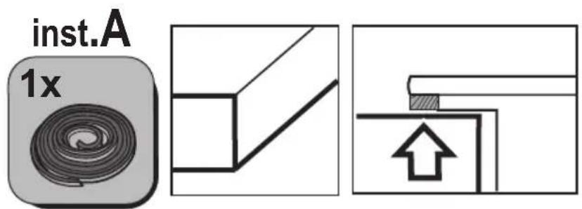
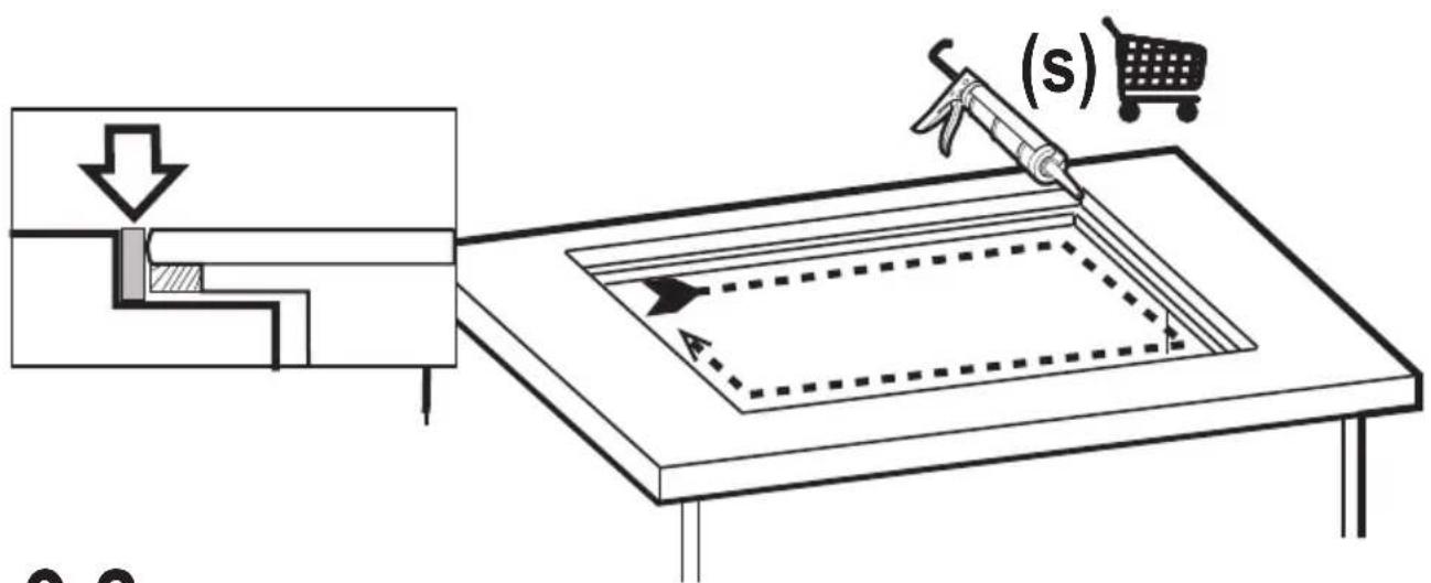
- Important: use a single component adhesive sealant (S). that can withstand high temperatures up to 250° before installation, the surfaces that need to be glued must be thoroughly cleaned, removing all substances that may compromise adhesion (e.g. release agents, preservatives, grease, oils, powders, old adhesive residue, etc.); the adhesive must be evenly spread along the entire perimeter of the frame; after gluing, leave the adhesive to dry for about 24 hours.
● Please note! Failure to install screws and fasteners in accordance with these instructions may result in electrical hazards.
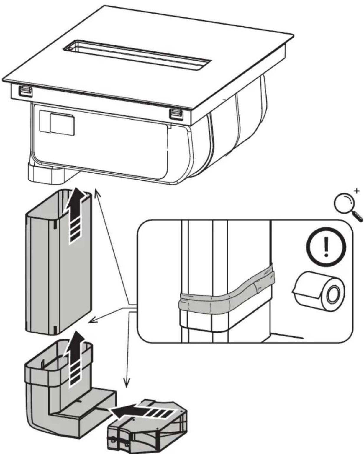
Note: for correct installation of the product, it is recommended to tape the pipes using an adhesive with the following characteristics: soft elastic PVC film with acrylic-based adhesive; complies with DIN EN 60454 regulations;
flame retardant: excellent resistance against wear; resistant to temperature fluctuations; can be used at low temperatures.
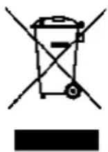
This device is marked in compliance with the European Directive 2012/19/EC - UK SI 2013 No.3113, Waste Electrical and Electronic Equipment (WEEE).
Make sure that this product is disposed of correctly. The user helps prevent potential negative consequences for the environment and for health. The symbol on the product or accompanying documentation indicates that this product should not be treated as household waste but should be handed over at a suitable collection point for the recycling of electrical and electronic equipment. Dispose of it in accordance with local regulations for waste disposal. For further information about the treatment, recovery and recycling of this product, please contact your local authority, the collection service for household waste or the shop from where the product was purchased. Device designed, tested and developed in compliance with regulations on: • Safety: EN/IEC 60335-1; EN/IEC 60335-2-6; EN/IEC 60335-2-31; EN/IEC 62233; • Performance: EN/IEC 61591; ISO 5167-1; 'ISO 5167-3'; ISO '5168; EN/IEC 60704-1; EN/IEC 60704-2-13; EN/IEC 60704-3'; ISO 3741; EN 50564; IEC 62301; EN 60350-2; • EMC: EN 55014-1; CISPR 14-1; EN 55014-2; CISPR 14-2; EN/IEC 61000-3-3; EN/IEC 61000-3-12. Recommendations for correct use in order to reduce the impact on the environment: When cooking begins, the device should be turned on at minimum speed, and left on for a few minutes even after cooking is complete. Increase the speed only if there is a large quantity of fumes and steam, using the Booster function only in extreme cases. To keep the odour reduction system running efficiently, replace the carbon filter/s when necessary. To ensure the
high performance of the grease filter, clean it when necessary. To improve efficiency and minimise noise, use the maximum duct diameter indicated in this manual.
USE
USING THE HOB
The induction cooking system is based on the physical phenomenon of magnetic induction. The main characteristic of this system is the direct transfer of energy from the generator to the pot.
Benefits: When compared to electric hobs, your induction hob is: Safer: lower temperature on the glass surface. Faster: shorter food heating times. More accurate: the hob immediately reacts to your commands. More efficient: 90% of the absorbed energy is transformed into heat. Moreover, once the pot is removed from the hob, heat transmission is immediately interrupted, avoiding unnecessary heat loss.
USE OF COOKWARE
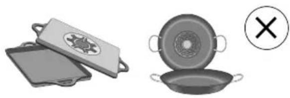
- Cookware

Only use pots bearing this symbol.
Important:
to avoid permanent damage. to the hob surface, do not use:
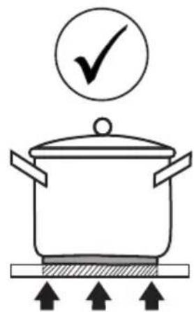
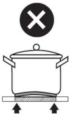
- cookware with a base that is not perfectly flat;
- metal cookware with an enamelled base;
- cookware with a rough base, to avoid scratching the hob surface;
- never place hot pots and pans on the surface of the hob's control panel.
- Not all induction pots work efficiently due to the base only partially consisting of ferromagnetic material! When purchasing pots or pans ensure that:
• the base is made entirely from terramagnetic material. If this is not the case, the efficacy of the transmission of heat is lessened and the uniformity of heat and the temperature of the pan/pot may not be suitable for cooking.
• The base does not contain aluminium: the cookware does not heat and may not be recognised by the inductors.
- Bases that are not flat or that have a rough surface take away the contact surface between the inductor and the cookware lowering its efficiency and worsening the cooking experience.
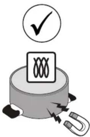
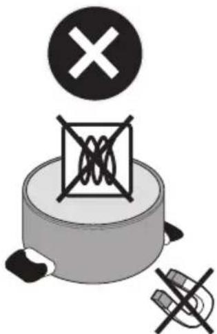
●Pre-existing cookware You can check if the pot material is magnetic simply by using a magnet. Pots are not suitable if they are not magnetically detectable. The indications from the previous paragraph also apply here.
Recommended pot bottom diameters IMPORTANT: if the pots are not of the correct size, the cooking zones will not switch on. To see the minimum pot diameters for each individual zone, consult the illustrated section of this manual.
natural_image
Illustration of cooking utensils including a pan, lid, and pan with a crossed-out mark (no text or symbols)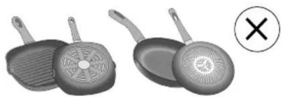
natural_image
Two cooking panes with handles and a crossed-out circle containing an 'X' symbol (no text or labels)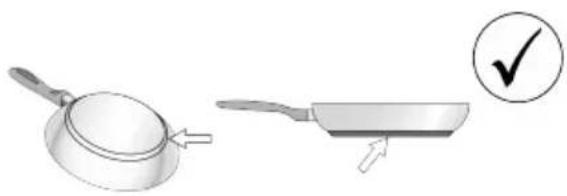
natural_image
Illustration of a frying pan and its cooking step with a checkmark (no text or symbols)Please note: To preserve cooking performance and product quality, the use of induction adapters is NOT recommended.
● Energy saving
Use pots and pans with a bottom diameter equal to that of the cooking zone; Use only pots and pans with flat bottoms; - Where possible, keep the lid on pots during cooking; Cook vegetables, potatoes, etc. with a minimal amount of water to reduce the cooking time; Use the pressure cooker, as it further reduces energy consumption and the cooking time; Place the pot in the centre of the cooking zone drawn on the hob.
USING THE EXTRACTOR FAN
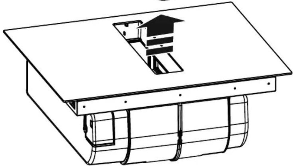
The extraction system can be used in the duct-out version with external evacuation, or in the recirculating version with filtering and internal recirculation.
Recirculating Version;
The extracted air will be filtered in special grease filters and odour filters before being sent back into the room. This product includes filters and piping for an installation that allows air to escape from the cabinet. For further information on the accessories supplied, see the illustrated part of this manual.
OPERATION
CONTROL PANEL
flowchart
graph TD
    subgraph TopPanel
        A["RL"] --> B["FL"]
        C["RR"] --> D["FR"]
        B --> E["HOOD"]
        D --> E
        E --> F["P"]
        G["2 RL 3 RL 6a RL 9 RL"] --> H["HOOD"]
        I["12 RL 13 RL 15 RL"] --> H
        J["14 RL 2 RR 3 RR 6a RL"] --> K["HOOD"]
        L["2 RR 8 RR 9 RR"] --> M["HOOD"]
        N["HOOD"] --> O["HOOD"]
    end
    subgraph BottomPanel
        P["4 RL 7a RL 6b RL 7b RL"] --> Q["TIMER FILTER"]
        R["4 RL 8a RL 8b RL"] --> Q
        S["4 RL 2 RR"] --> T["HOOD"]
        U["2 RL 3 RL 6a RL"] --> V["HOOD"]
        W["2 RL 3 RL 6a RL"] --> X["HOOD"]
        Y["2 RL 3 RL 6a RL"] --> Z["HOOD"]
        AA["2 RL 3 RL 6a RL"] --> AB["HOOD"]
        AC["2 RL 3 RL 6a RL"] --> AD["HOOD"]
        AE["2 RL 3 RL 6a RL"] --> AF["HOOD"]
    end
    style TopPanel fill:#f9f,stroke:#333
    style BottomPanel fill:#bbf,stroke:#333
| Function | |
| 1 | ON/OFF of the hob / hob extractor fan |
| 2 | Cooking zone selection key |
| 3 | Cooking zone power level display |
| 4 | Active cooking zone LED / Active filters saturation LED |
| 5 | Increase/decrease cooking power level and extraction speed (power) |
| 6 | Egg timer activation (Stand Alone) |
| 6a - 6b | Active Egg Timer LED (Stand Alone) |
| 7a-7b | Cooking zone timer display / Carbon filter saturation display - Grease filter |
| 8a-8b | Timer Display Increase/Decrease |
| 9 | Temperature Manager activation (Warming Function) |
| 10 | Pause |
| 10a | Active pause LED |
| 11 | Key Lock |
| 11a | LED - Key Lock |
| 12 | Extractor selection key |
| 13 | Extractor Display |
| 14 | Extractor automatic function activation |
| 15 | Extractor delay menu LED |
THINGS TO KNOW BEFORE STARTING
WARNING: After initial connection of the product to the mains, the hob requires a RELEASE procedure. Proceed as indicated:
Connect the hob to the power supply; the display (13) will show a flashing 8 and the LED (11a) on. Press the key (11) for a few seconds, the LED (11a) will switch off. Now it will be possible to turn on the Hob with the ON/OFF key
All functions of this hob are designed to comply with the most stringent safety regulations. For this reason:
• Some functions will not be activated, or will be automatically deactivated, in the absence of pots on the burners or when they are poorly positioned.
- In other cases the activated functions will be automatically deactivated after a few seconds, if the specific function requires a further setting that has not been selected (e.g.: "Turning the hob on" without "Selecting the cooking zone" and the "Operating temperature", or the "Lock Function" or the "Timer" function).
Wait for the display to turn off before approaching the cooking zone.
Please note! In the case (for example) of prolonged use, the cooking zone may not immediately shut down because it is in the cooling phase; the symbol will appear on the cooking zone display to indicate that this phase is under way. Wait for the display to turn off before approaching the cooking zone.
COOKING ZONE DISPLAY
The following is shown on the cooking zone displays:
| Function Value | |
| Cooking zone on | 0 |
| Power Level | 1...9-P |
| Residual Heat Indicator | H |
| Pot Detector | Y |
| Temperature Manager Function active | 0-8-0 |
| Bridge Zone Function active | A |
| Pause function | H |
| Automatic Heat UP function | A |
CHARACTERISTICS OF THE HOB
Safe Activation
The product is activated only in the presence of pots on the cooking zone: the heating process does not start or is interrupted if there are no pots, or if these are removed.
Pot Detector
The product automatically detects the presence of pots on the cooking zones.
Safety Shut Down
For safety reasons, each cooking zone has a maximum operating time, which depends on the power level set.
Residual Heat Indicator
When switching off one or more cooking zones, the residual heat is indicated with a specific visual signal on the display of the corresponding zone by the symbol :
USING THE HOB
Power-on
The hob is switched on by touching the ON/OFF key (1) All the displays (3) and the display (13) will turn on and show the number zero □
To switch off the hob, press the ON/OFF key(1).
The hob switches off after a few seconds if no functions are activated.
●Cooking zone activation
Activation:
Enter the cooking zone menu by pressing one of the keys zone. The display (2) corresponding to the desired cooking zone. The display (3) of that zone is the only one to be lit at high intensity. Touch and slide a finger on the selection bar (5) to adjust the power of the previously selected cooking zone. Note: When a cooking zone is selected, the TIMER display (7a+7b) will show this: .the LED (4) 'that turns on defines which zone has been selected, in this case the FL zone.
Deactivation:
Enter the menu of the desired cooking zone and press one of the keys (2). The display (3) of that zone will remain the only one lit at high intensity. bring the power to Zero, or press the key (2) again, holding it down for a few seconds.
● Cooking Power Level Zone
The hob features 9 power levels. Touch and slide your fingers along the Selection bar (5): to the right to increase the power level;
to the left to decrease, the power level.
The power level set will be shown on the display (3) of the chosen cooking zone.
Power Booster
The product is equipped with 1 additional power level (after level 5), which remains active for 10 minutes, after which the power returns to the previous level. Touch and slide your fingers along the Selection bar (5), past the level. To activate the Power Booster..The Power Booster level is indicated on the Display (3) with the symbol P.
key lock
The Key Lock allows you to lock the settings of the hob to prevent accidental tampering with the same, while leaving the set functions enabled.
Activation:
To activate the key lock function, the hob must be switched on.
- press (1) for 2 sec. Repeat the operation to deactivate. Note: if any other function is pressed while key Lock is active, the LED (11a), will flash and the display (7b), will show a sequence of symbols indicating that the function is in use and must eventually be deactivated in order to act on the hob.
Bridge Zones
This function allows the FL cooking zone to work in combination with the RL cooking zone and the FR cooking zone with the RR cooking zone, creating a single zone with the same power level. This will allow evenly distributed cooking
with large-sized pots and pans. Always check in the assembly illustrations, in the final part of the manual, in which zones the bridge can be activated.
To activate the Bridge Function:
Simultaneously press the key (2) of the two selected zones (FL+RL) or (FR+RR) for a few seconds.
One of the displays (3) will show the symbol, while the other display (3) will show the power that will be set. To set the power, scroll with your finger on the selection area (5) To deactivate the Bridge Function:
• press simultaneously for a few seconds the keys (2) of the pair of zones to be deactivated (FL+RL) or (FR+RR).
● Temperature manager (Worming Function)
The Temperature Manager (Worming Function) is a control function that allows you to keep the heat at a constant temperature at an optimised power level; this feature is ideal for keeping ready meals warm.
Activation:
Select key (2) and then key ⌘≡ (9) of the zone to be used; the display (3) of that zone will show a sequence of symbols, which will last for as long as the function remains active.
Deactivate:
Press the key (9) again for a few seconds to deactivate the function. Note: the function can also be enabled in zones with BRIDGE active.
Automatic Heat UP
The Automatic Heat UP function allows the set power to be reached more quickly; with this function it is possible to cook food faster without the risk of burning it, insofar as the temperature does not exceed the set level. This function is available for power levels from to .8
Activation:
Select key (2) of the zone to be used then scroll with your finger in the selection bar (5). Having reached the desired level, keep it pressed for a few seconds until the symbol appears on the display (3) of that zone, alternating with the set power. By increasing the power level of the cooking zone, the Automatic Heat Up function remains active, with the new temperature setting;
Note: This function can be activated on several zones at the same time.
Deactivate:
Select key (2) of the zone from which the Automatic heat Up is to be removed and decrease the power level of the cooking zone.
Pause
The Pause function allows active functions on the hob to be suspended, bringing the cooking power to zero.
Activation:
- press the key II (10) the LED (10a) comes on and the flashing symbol, as displayed on the display (3) of the active zones, alternating with the temperature level set in those zones.
Deactivate:
- press the key (10) for a few seconds until the symbol disappears.
With deactivation, the hob resumes working with the settings set before the pause. Note: if after 10 minutes, the Pause Function is not deactivated, the hob will turn off automatically. Note: the Pause Function does not affect the extraction.
Egg Timer
The Egg Timer function is a countdown independent of the cooking zones (and the extraction zone).
Activation:
Exit the Suction or Cooking Zone menus so that all LEDs (3 and 13) are lit.
Press the key Ⓛ (6), the LED (6a) will light up and, at the same time,
the display (7a+7b) with the LED (6b) will also be ac- tivated.
It will now be possible to increase or decrease the time using the keys + (8a) and — (8b). The time is expressed in minutes. If the timer reaches a time of less than one minute, the countdown continues by displaying the seconds.
When the timer has finished the countdown, an acoustic signal sounds and the cooking zone switches off.
Deactivate:
To switch off the Timer early, exit the Suction or Cooking Zone menus so that all LEDs' (3 and 13) are lit and set the Timer display to Zero with the key _(8a).
Cooking Zone Timer
The Cooking Zone Timer function is a countdown that can be set, even simultaneously, on each cooking zone. At the end of the period set, the cooking zones switch off automatically and the user is notified with a dedicated acoustic signal.
Activation:
Note: this timer can only be started if the cooking zone is active with power other than zero.
After, activating the desired cooking, zone, key (2).
the display (7a+7b) will activate and it will be possible to program the timer. To increase or decrease the time use the keys + (8a) and - (8b). The time is expressed minutes. If the timer reaches a time of less than 1 minute, the count continues while displaying the seconds.
If desired,, repeat the operation for several cooking zones:
Each cooking zone can have a different limer set; the countdown of the cooking zone selected at that moment will appear on, the display (7a+7b).
Note: After activating the Bridge zone, the timer on this zone can also be started.
Deactivate
To switch off the Timer in advance, select the cooking zone key (2) and press key — (8a) until the timer reaches zero. The time will deactivate.
Power Limitation.
The Power Limitation function allows the product to be used while limiting its maximum absorption, adjusting the absorbed power in all active cooking zones, ensuring that the total absorbed power of the hob does not exceed the set maximum absorption level.
The Power Limitation management menu is located inside the Parameter management menu.
To enter the parameter management menu:
Disconnect the hob from the power supply, wait a few seconds and reconnect the hob to the power supply. UN-
LOCK the hob by holding down the key (10) for a few
seconds; subsequently press the keys (12) + (14) simultaneously for a few seconds until the scroll bar (5) lights up. Slide your finger along the entire bar (5) from left to right. The two displays (3-FL) and (3-FR) will light up. The Display (3-FL) indicates the parameter being modified. Display (3-FR) indicates the set value.
To go to the Power Limitation management menu: By default, accessing the parameters menu, the display (3-FL) alternately shows the values and press the key (9-FL) several times until the display (3-FL) shows the values and alternately. (and = Power Limitation management menu).
Set Power limitation value: press the key (9-FR) to select the desired value from the three available, see table below:
| Zone3-FL | Zone3-FR | Powervalue (KW) |
| 0.2 | 0 | 7.4 |
| 0.2 | 1 | 4.5 |
| 0.2 | 2 | 3.1 |
Saving settings:
To save the selected settings, press the key (1)
USING THE EXTRACTOR
● Extractor activation. Activation:
Touch (press) the key ☐ (12). The display (13) will turn on at high intensity. Touch and scroll with a finger on the selection bar (5) to adjust the fume extraction power. Note: unlike the cooking zones, switching off the extractor fan cannot be programmed using a timer. Therefore the display (7a+7b) will not activate. Deactivation:
To turn off the extractor fan, hold down the key (12) for a few seconds or bring the extraction power to Zero.
Extractor Power Level
The extractor fan is equipped with 4 extraction power levels plus a Booster. Touch and slide your fingers along the Selection bar (4): to the right to increase the power level; to the left to decrease the power level. The set power level will be shown on the display (13) of the extractor fan.
Extractor.Power.Booster
The product is equipped with 1 additional BOOSTER power level (over level 4) which remains active for 5 minutes, after which the power returns to the previous level. Touch and slide your fingers along the Selection bar (5), past the level 4 to activate the Power Booster..The Power Booster level is indicated on the Display (13) with the symbol P
Automatic mode
The product will turn on at the most suitable speed, adapting the extraction capacity to the maximum cooking level used in the cooking zones. When the cooking zones are switched off, the hood adapts its extraction speed, decreasing it gradually, to eliminate residual vapours and odours.
Activation.
Enter the extractor Manu by pressing the key (12) then press the key (14); the letter R will appear on the display (13) alternating with the fan speed value.
'Deactivate:'
From the extractor fan menu, press the key (14) or manually decrease the extractor fan speed from the selection bar (5).
●Filter management menu:
Conditions required to enter the menu: The COOKING ZONES and EXTRACTOR must all be powered □ The EGG TIMER must be Off. If these conditions are not respected, by performing the access procedure, the display (7a+7b) will indicate ,and it will not be possible to continue further.
To access the menu and view the status of the filters:
After complying with the input requirements indicated above, press key (12), then press —(8a) and +(8b) simultaneously for 4 seconds. At this point we will find ourselves in the Filter management menu.
By default, the display (7a+7b) will show the status of the GREASE FILTER. To switch to viewing the status of the ODOUR FILTER, press (8a). Each time this key is pressed, the display switches from one filter to another, consecutively. Below is a table of filter statuses.
| Filter Status Display | |
| ACTIVE grease filter* | .05. |
| ACTIVE odour filter* | .F3. |
| DEACTIVATED grease filter | G- |
| DEACTIVATED odour filter | F- |
*When the filter saturation indicator is ACTIVE the display (7b) will show the status of the filter with a value from (maximum efficiency) to ① saturated filter).
To turn the filter saturation indicator on or off:
After selecting one of the two filters, press + (8b); with each press, the display switches from one state to another consecutively.
Note: Deactivating the filter and then reactivating it in the same session, the value of the filter state remains unchanged from before deactivation. Exiting the menu after having deactivated the filter when the filter is reactivated the filter saturation value will restart from 8
To exit the Menu:
To exit the Menu, press any key EXCEPT key (8a) and +(8b) or wait 8 seconds without touching any other keys.
Reset filter saturation
While one or both signals are active, it is possible to reset the filter saturation alarm. In the first 10 seconds in which the filter saturation signal appears, press (8a) and (8b) simultaneously for a few seconds. An acoustic signal indicates the successful reset. It is advisable to perform this procedure ONLY after having replaced the filters. Note: If both alarms are active, perform this operation twice to reset both alarms.
●Extractor fan switch off delay
With this function activated, the extractor fan will remain on for a pre-set time. Once this time has elapsed it will switch off automatically. Each speed has a specific timer as indicated in the table below.
To activate: With the extractor fan running, press and hold the selection bar (5) and the LED (15) will light up, indicating that the function has been activated. To deactivate: simply change the extraction speed to deactivate this function. LED (15) will turn off, indicating that the function has been deactivated.
| Power level Cooking type | Use (based on cooking experience and habits) | ||
| Max power | P | Heat quickly | raises the temperature of food in a short space of time to boiling point for water, or to quickly heat cooking liquids. |
| 8-9 | Fry - boil | crowning, starting cooking, fry frozen products, boil quickly | |
| High power | 7-8 | Brown - fry - boil - grill | crowning fast rolling boil, cooking and grilling (for brief periods, 5-10 minutes) |
| 6-7 | Brown - cook - stew - fry - grill | crowning slow rolling boil, cooking and grilling (for medium periods, 10-20 minutes), pre-heat accessories | |
| Medium power | 4-5 | Cook - stew - fry - grill | stewing, light rolling boil, cooking (for long periods), dressing pasta |
| 3-4 | Cooking - simmering - thickening - creaming | longer cooking rice sauces, roasts, fish with accompanying liquids (e.g. water, wine, stock, milk), dressing pasta | |
| 2-3 | Cooking - simmering - thickening - creaming | longer cooking (volumes less than one litre rice sauces, roasts, fish) with accompanying liquids (e.g. water, wine, stock, milk) | |
| Low power | 3-2 | Melt - thaw - keep warm - stir | melting butter gently melting chocolate, derrosting small products |
| 8 | Melt - thaw - keep warm - stir | keeping small portions of just-cooked food warm or maintaining dishes at serving temperature and creaming risottos | |
| OFF | 0 | Support surface | Hob in stand-by or off (possible presence of residual heat from the end of cooking, signalled by H-L-O) |
MAINTENANCE
Please note! Before any cleaning or maintenance, make sure the cooking zones are switched off and the heat indicator has turned off.
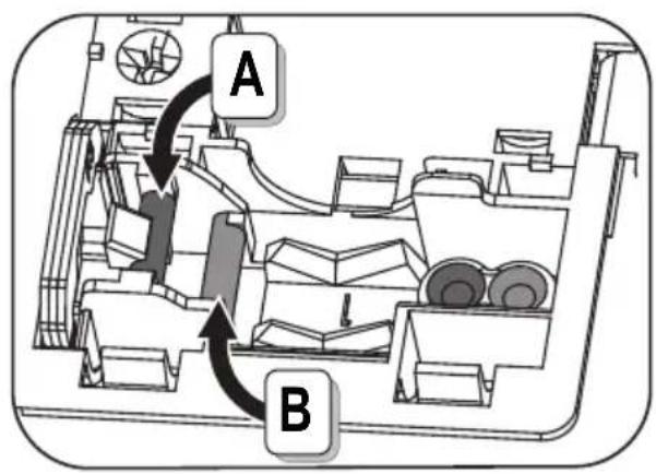
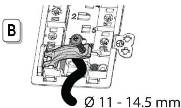
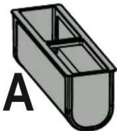
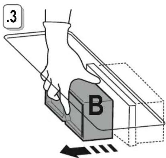
| × | For product maintenance, see the images at the end of the installation marked by this symbol. |
HOB MAINTENANCE
● Cleaning the induction hob
The hob must be cleaned after each use.
Important:
• Do not use abrasive sponges, scouring pads. Their use, over time, may ruin the glass.
• Do not use irritant chemical detergents such as oven sprays or stain removers.
: 'DO NOT USE STEAM JET CLEANERS!!!
After each use, leave the hob to cool and clean it to remove deposits and stains caused by food residue. Sugar or food with a high sugar content damage the hob and must be removed immediately. Salt, sugar and sand may scratch the glass surface. Use a soft cloth, paper towel or specific products to clean the hob (follow the Manufacturer's instructions).
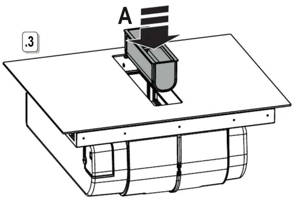
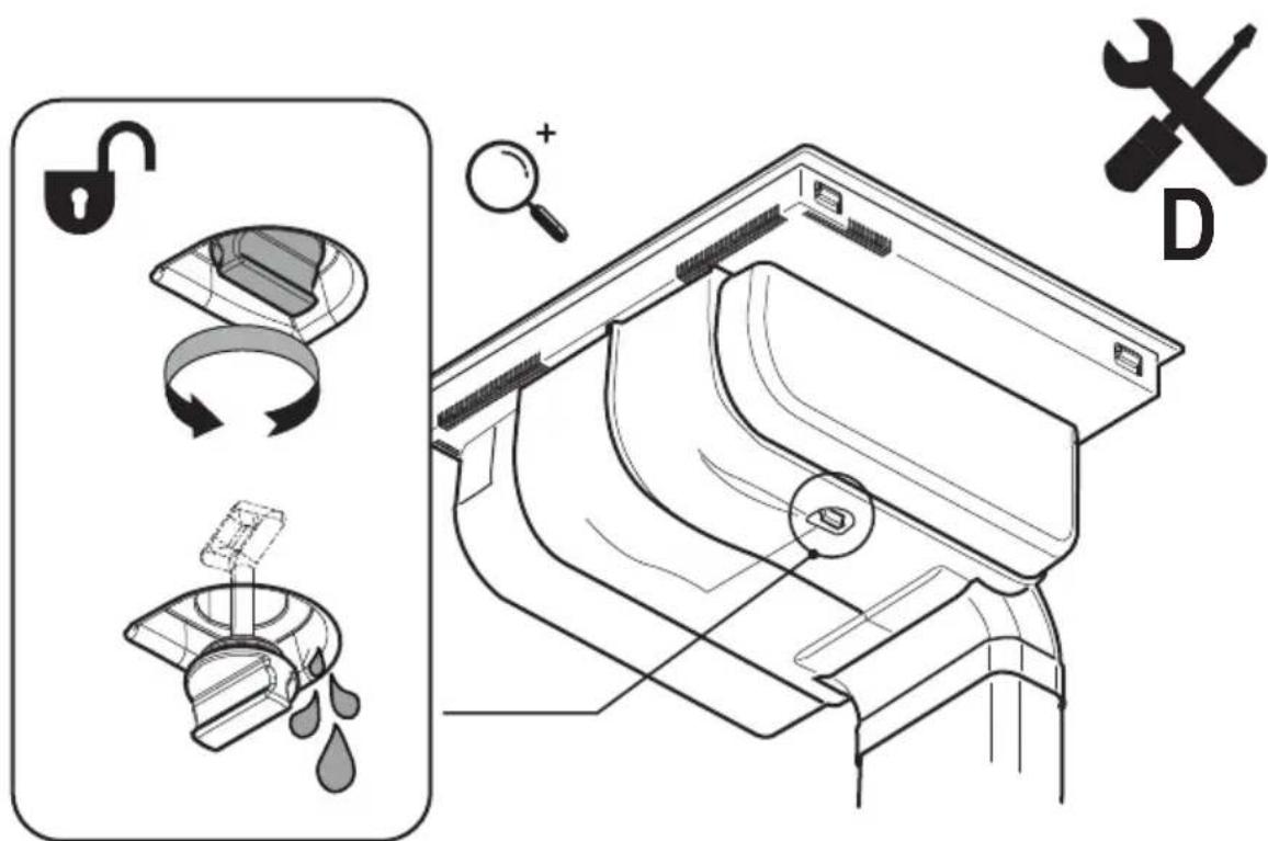
● Cleaning the liquid collection channel. :
In the event, large quantities of liquids accidentally spill out of the pots, they can be drained using the drain valve on the bottom part of the product, so as to eliminate any residue and ensure maximum hygiene levels.
Cleaning the metal grille:
The grille must be washed by hand with hot water and neutral detergent, then dried thoroughly to prevent oxidation.
For cleaning, use ONLY a cloth moistened with neutral li- liquid detergents.
DO NOT USE CLEANING UTENSILS OR TOOLS!
Avoid the use of products containing abrasives. DO NOT USE ALCOHOL!
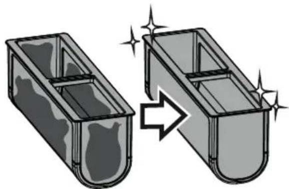
- Grease filter maintenance:
Traps grease particles generated by cooking.
Must be cleaned once a month (or when indicated by the filter saturation indication system), with non-aggressive detergents, either by hand or in the dishwasher at low temperatures and in a short cycle. When cleaned in the dishwasher, the metal grease filter may discolour, but its filtering characteristics remain unchanged.
● Ceramic activated carbon filter maintenance (For Recirculating Version only):
Traps unpleasant odours generated by cooking. The product comes with a set of odour filters.
The saturation of the odour filters can occur after somewhat prolonged use depending on the type of cooking and how regularly the grease filter is cleaned. The odour filters can be thermally regenerated every 2/3 months in an oven pre-heated to 200°C for 45 minutes. The correct regeneration of the filter ensures that it can constantly filter efficiently for 5 years.
Please note! Do not place the filters on the floor of the oven but rather in a tray, positioned at an intermediate height.
ASSISTANCE
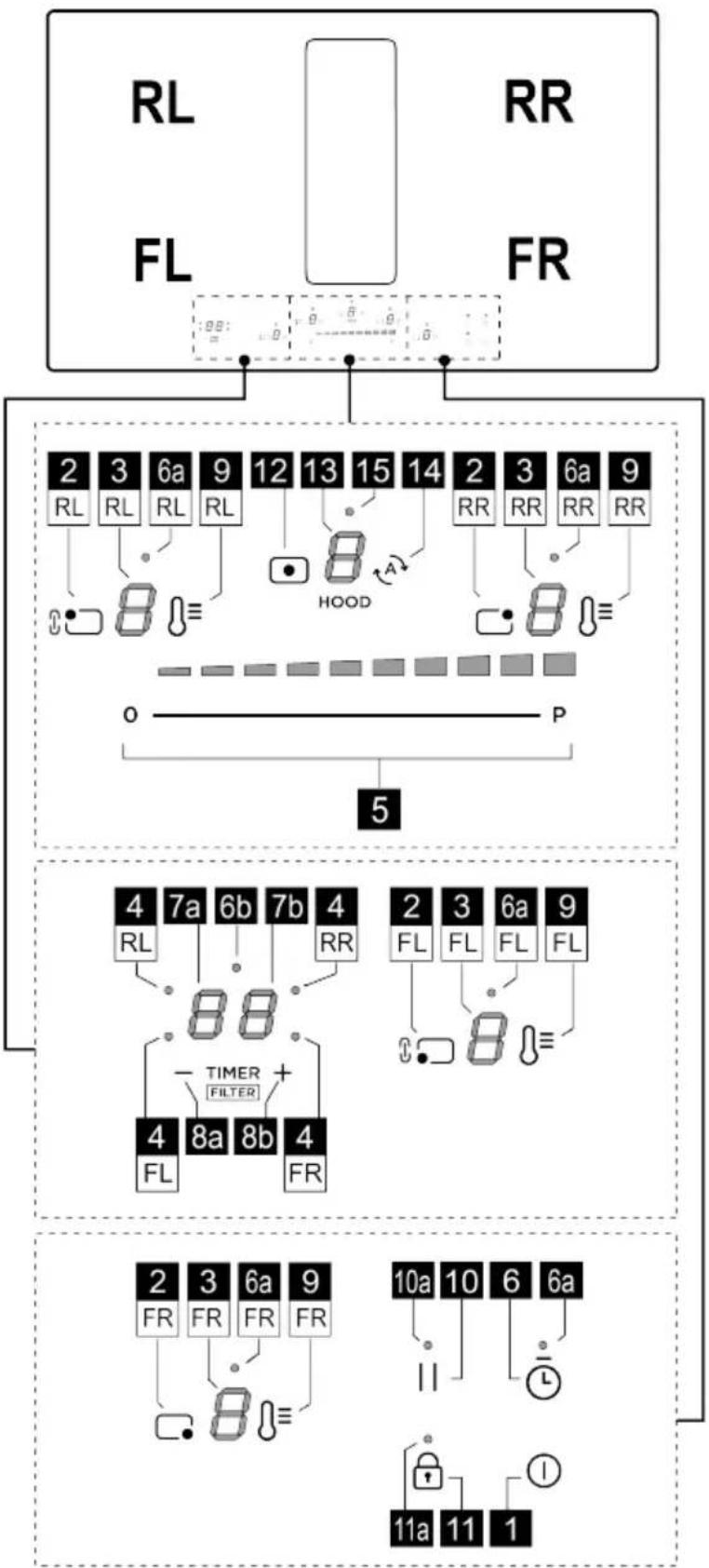
| Informative code | Description | Possible causes | Solution |
 | The command zone switches off due to an excessively high temperature | The temperature inside the electronic parts is too high | Wait for the hob to cool before re-using it |
| For all other error signals | Call customer service and report the error code | ||
CUSTOMER SERVICE
Before contacting Customer Service
- Check that "the problem cannot be solved by consulting the points in 'Troubleshooting'.
- Switch the device off and on again to see if the problem resolves itself.
If the fault persists after the above checks, contact the nearest Customer Service centre.

natural_image
Black rectangular object with a vertical rod and horizontal line, no visible text or symbols

natural_image
Two identical black silhouette figures of men, no text or symbols present
natural_image
Simple line drawing of two hands (no text or symbols)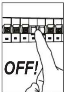

natural_image
Illustration of two types of medical or industrial tools: a measuring tape and a syringe (no text or symbols present)
natural_image
Line drawing of a mechanical device with a handle and base (no text or symbols)
natural_image
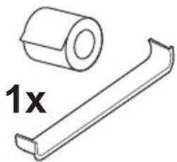
Simple line drawing of an open box next to a house with a circular arrow symbol (no text or labels)1x
2,8 m
1x
natural_image
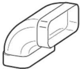
Technical line drawing of a cylindrical component and a rectangular bracket (no text or symbols)1x
natural_image
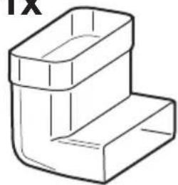
Simple line drawing of a rectangular object with curved internal sections (no text or symbols)1x
natural_image
Line drawing of a 3D L-shaped bracket or L-shaped object (no text or symbols)
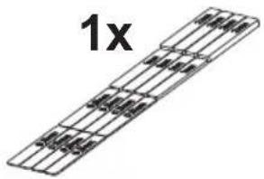
2x
M4x20mm
2x

1x
natural_image
Simple line drawing of a rectangular block with horizontal lines, no text or symbols present1x
natural_image
Simple line drawing of a 3D geometric block with no text or symbols2x
1+2
RL
2
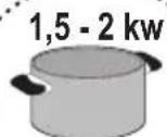
min. ∅ 110mm
∅ 180mm
1
FL
min. ∅ 110mm
∅ 180mm
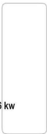

ON/OFF
1,5 - 2 kw
min. ∅ 110mm
RR
3
∅ 210mm
min. ∅ 110mm
∅ 160mm
4
FR
3 kw
min. ∅ 180mm
FRONT
inst.A

inst.B
inst.A
natural_image
Technical line drawing of a device with a circular component and a rectangular block, no visible text or symbols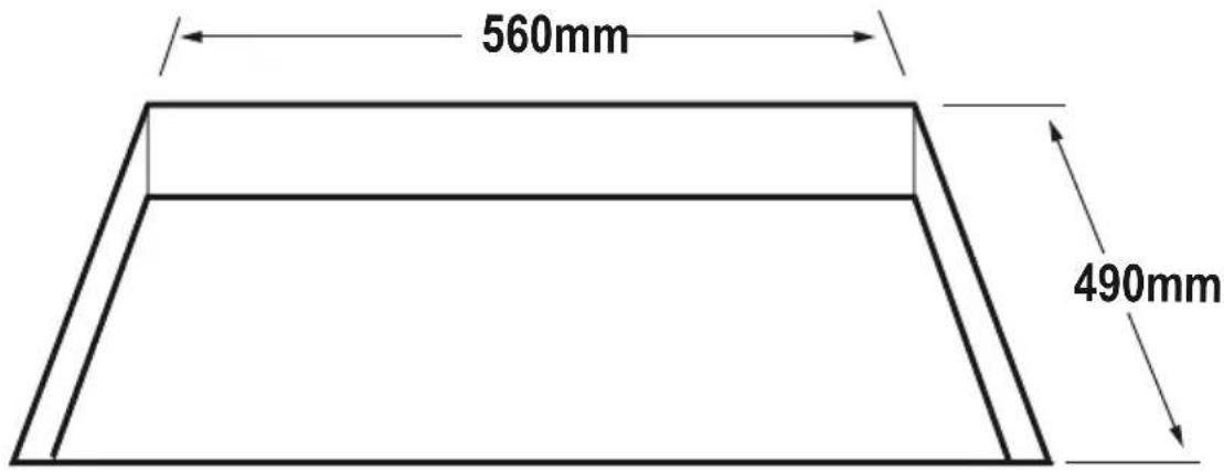
inst.B
natural_image
Simple line icons: a house with an upward arrow and a shopping cart (no text or symbols)KIT WINDOW

V-Hz
natural_image
Simple line drawing of a window with sound waves and a sensor, no text or symbols present
OFF
natural_image
Simple line drawing of a door with sound waves and a small square object on the left (no text or symbols)
ON
natural_image
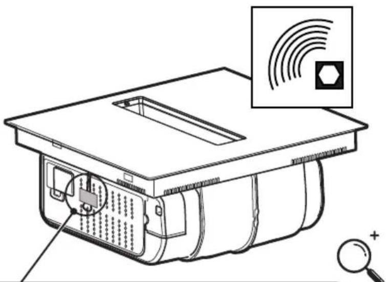
Technical line drawing of a device casing with internal components and a magnifying glass nearby (no text or symbols)
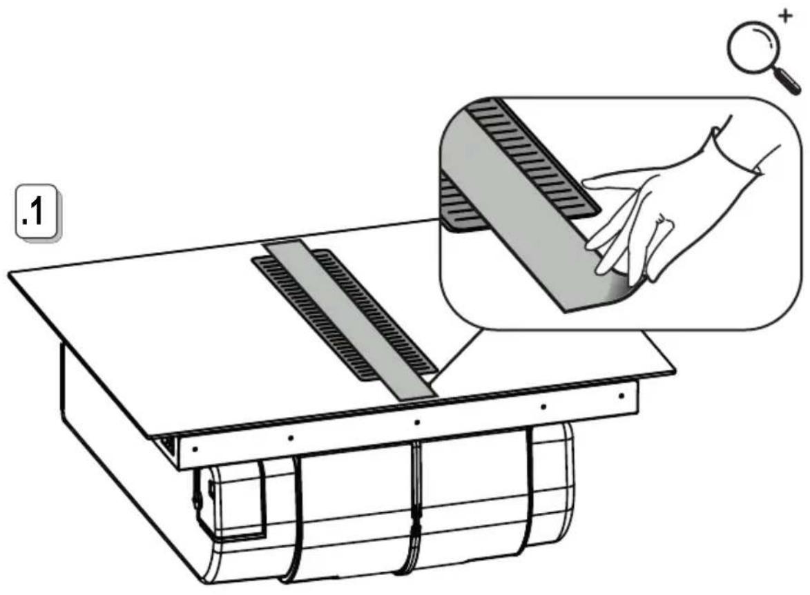
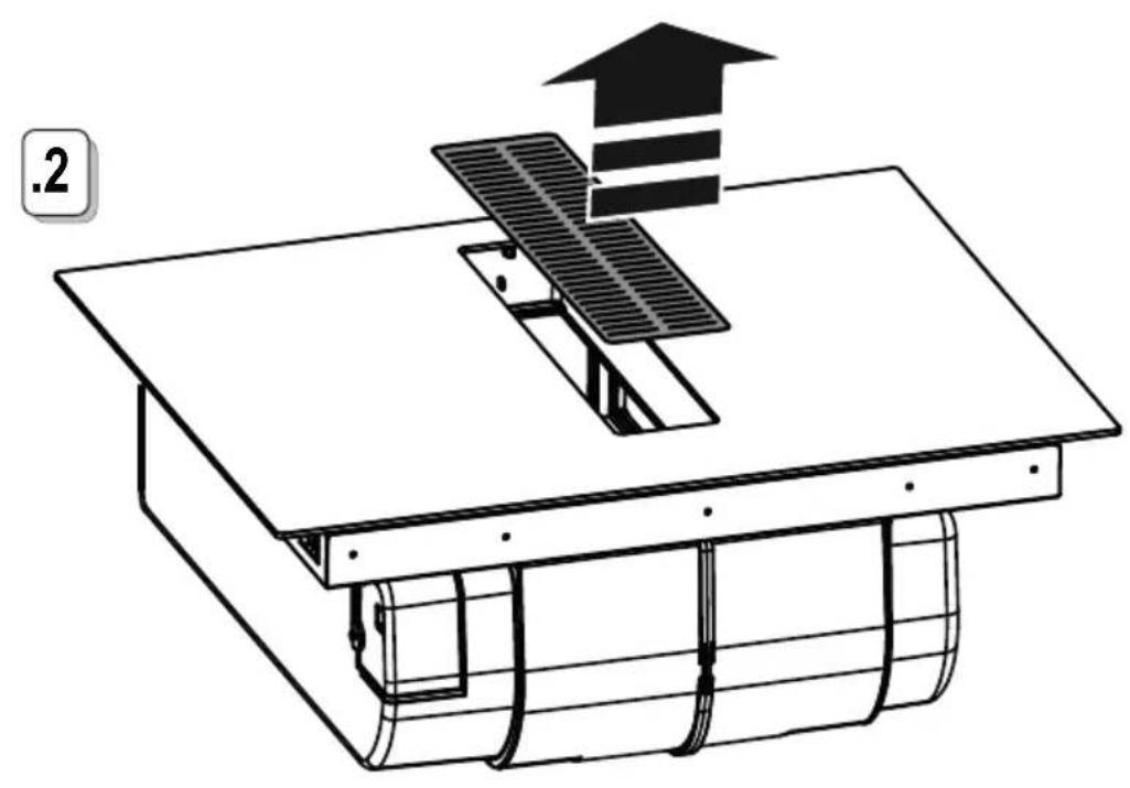
natural_image
Diagram of a solar panel installation with a rising arrow and coil, no text or symbols present!
natural_image
Technical line drawing of a mechanical assembly with a component and housing (no text or symbols)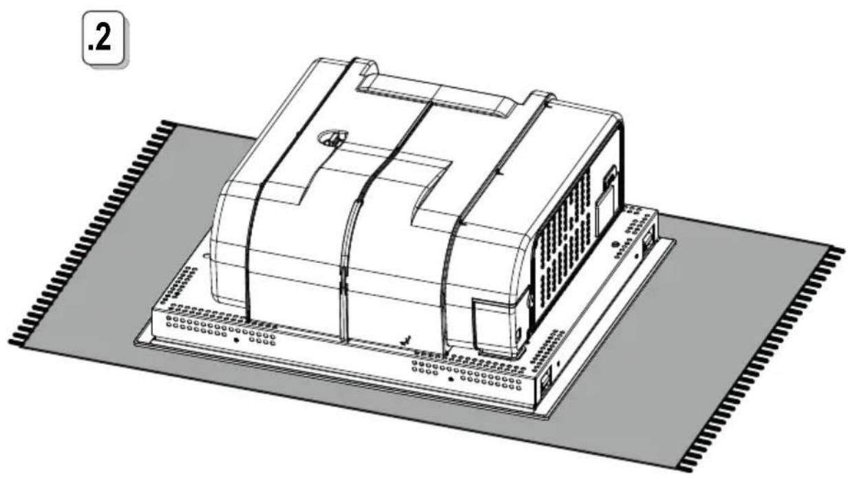
natural_image
Technical line drawing of a device with internal components and mounting base (no text or symbols)6.1
220V-240V \~ 50Hz/60Hz
7
380V-415V \~ 2N\~
50Hz/60Hz

V-Hz
220V-240V \~ 2N 2L 50Hz/60Hz


7.1

natural_image
Line drawing of a computer chassis with hands installing components on a base (no text or symbols)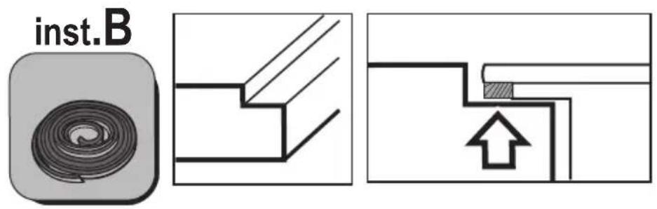
natural_image
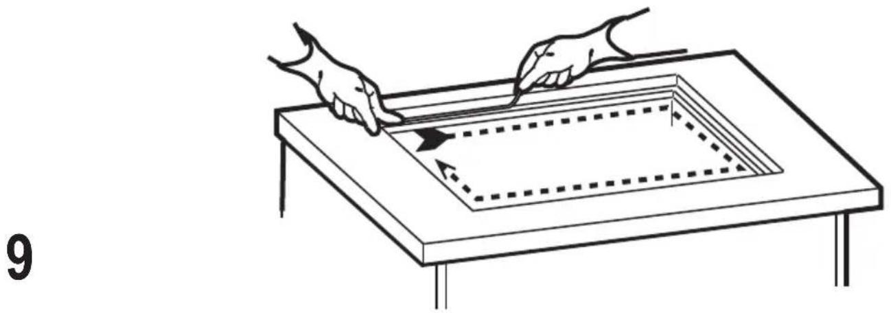
Line drawing of a hand using a tool to cut a square frame on a table, with arrows indicating direction (no text or symbols)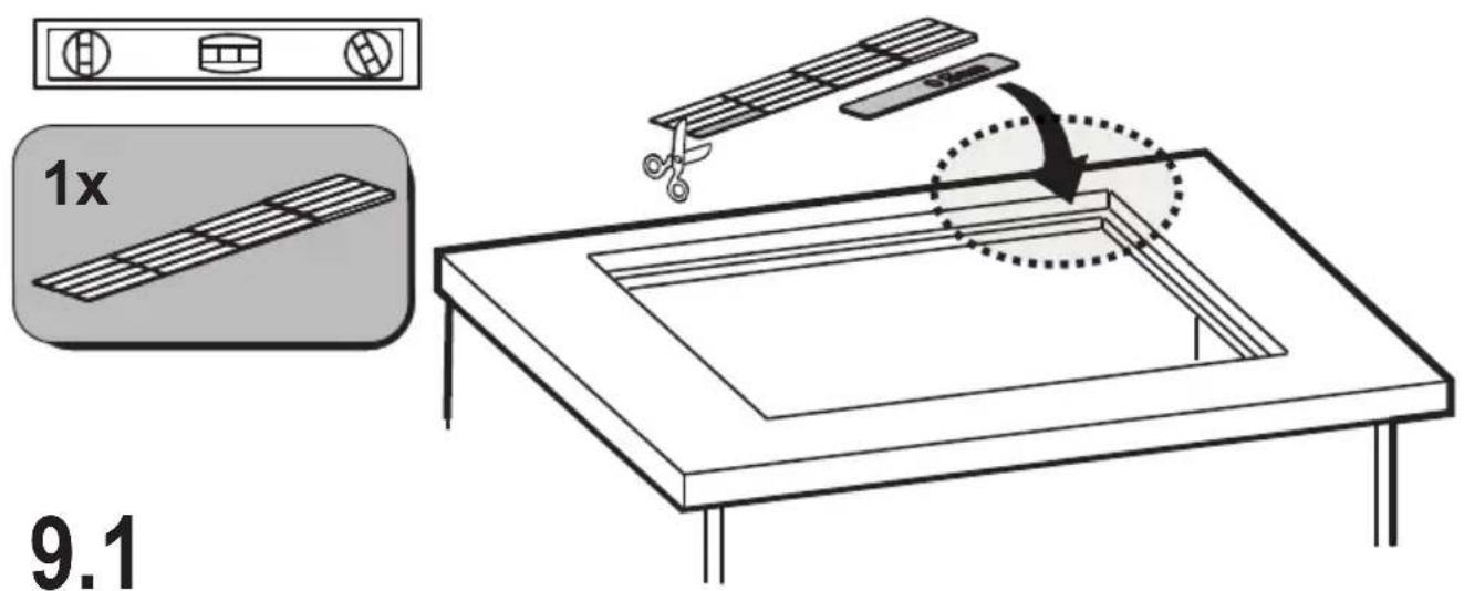
9.2
10
! L ≤ 650mm

natural_image
Technical line drawing of a mechanical assembly with no visible text or symbols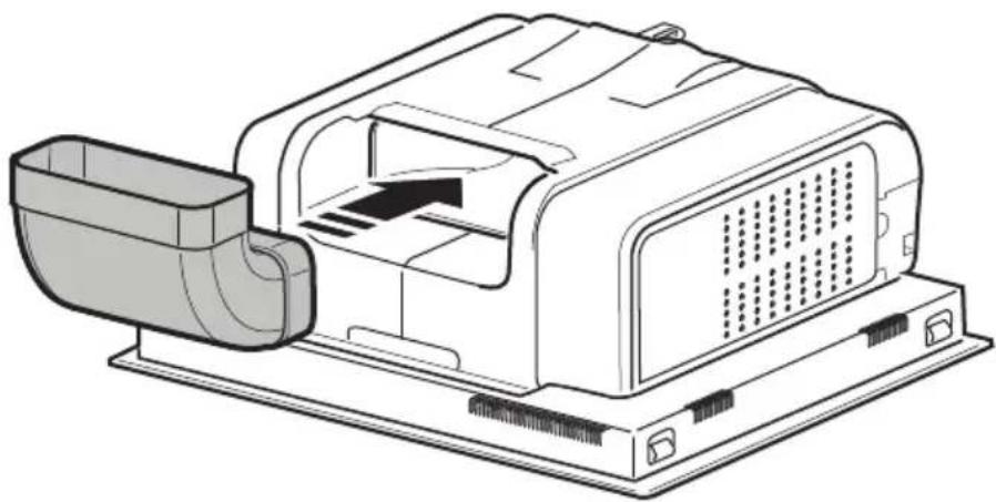
natural_image
Technical line drawing of a mechanical device with a housing and internal components (no text or symbols)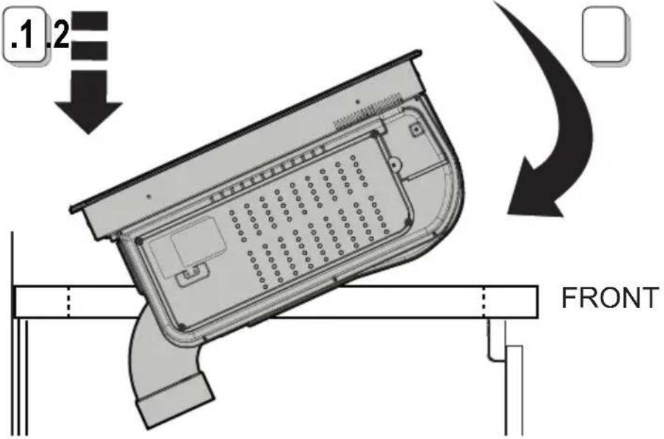
10.1
KIT0167756
.1
natural_image
Simple 3D diagram of a rectangular container with a curved side, labeled 'A' (no text or symbols on the container itself)
A-B
natural_image
Technical line drawing of a mechanical assembly with a central housing and coiled components (no text or symbols)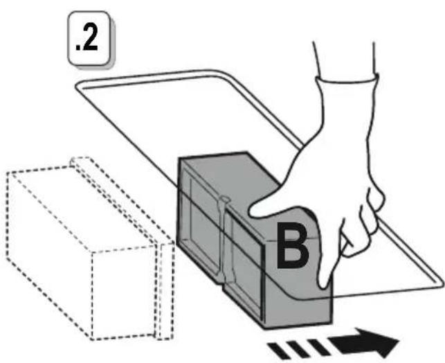
natural_image
Diagram showing two 3D rectangular containers with different fill patterns, one being rotated by a starburst effect (no text or symbols)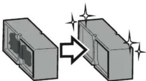
natural_image
Diagram showing two 3D rectangular blocks with internal structures and a transformation arrow, no text or symbols present12.0
natural_image
Simple 3D illustration of a rectangular box with a side panel, labeled '2x' (no other text or symbols)
A-B
12.1
A-B-E

natural_image
Diagram of a device with a screen and a triangular panel, placed on a table (no text or symbols)12.2
13

natural_image
Simple line drawing of a cooking pot with an 'X' symbol above it and arrows indicating upward pressure (no text or labels)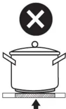
natural_image
Simple line drawing of a cooking pot with a cross symbol above it, no text or labels present.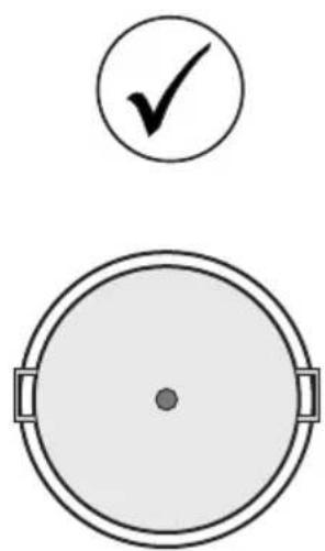
natural_image
Simple diagram showing a circular target with a checkmark above it and a smaller circle below, no text or symbols present.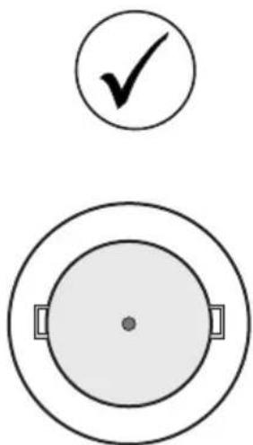
natural_image
Two circular diagrams with checkmark and rectangular handles, no text or symbols present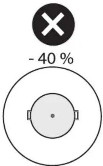

LE TRI + FACILE

BUT INTERNATIONAL
1 Avenue Spinoza
77184 Emerainville, France
LIB0200044 Ed.03/24


- SIGN ≤ TURE ®
- ● Residual Heat Indicator
- ● Temperature, manager, (Warming Function)
- ● Automatic, Heat UP.
- INDUCTION HOB
- INDEX
- INTRODUCTION
- SAFETY AND REGULATIONS
- GENERAL SAFETY
- ELECTRICAL CONNECTION SAFETY
- INSTALLATION SAFETY
- ● Preparing the cabinet for installation:
- USE
- USING THE HOB
- USE OF COOKWARE
- - Cookware
- Important:
- ● Energy saving
- USING THE EXTRACTOR FAN
- Recirculating Version;
- OPERATION
- CONTROL PANEL
- THINGS TO KNOW BEFORE STARTING
- COOKING ZONE DISPLAY
- CHARACTERISTICS OF THE HOB
- Safe Activation
- Pot Detector
- Safety Shut Down
- Residual Heat Indicator
- Power-on
- ●Cooking zone activation
- Activation:
- Deactivation:
- ● Cooking Power Level Zone
- Power Booster
- key lock
- Bridge Zones
- To activate the Bridge Function:
- ● Temperature manager (Worming Function)
- Deactivate:
- Automatic Heat UP
- Pause
- Egg Timer
- Cooking Zone Timer
- If desired,, repeat the operation for several cooking zones:
- Deactivate
- Power Limitation.
- To enter the parameter management menu:
- Saving settings:
- USING THE EXTRACTOR
- ● Extractor activation. Activation:
- Extractor Power Level
- Extractor.Power.Booster
- Automatic mode
- Activation.
- 'Deactivate:'
- ●Filter management menu:
- To access the menu and view the status of the filters:
- To turn the filter saturation indicator on or off:
- To exit the Menu:
- Reset filter saturation
- ●Extractor fan switch off delay
- MAINTENANCE
- HOB MAINTENANCE
- ● Cleaning the induction hob
- ● Cleaning the liquid collection channel. :
- Cleaning the metal grille:
- ASSISTANCE
- CUSTOMER SERVICE
- 1+2
- FRONT
Brand : SIGNATURE
Model : STI70ASPI
Category : Cooker