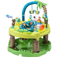
Exersaucer Life In The Amazon Triple Fun - Baby products Evenflo - Free user manual and instructions
Find the device manual for free Exersaucer Life In The Amazon Triple Fun Evenflo in PDF.


| Product Type | 3-stage Activity Center |
| Brand | Evenflo |
| Model | Exersaucer Life In The Amazon Triple Fun |
| Recommended Age | From birth to 24 months (depending on stage) |
| Max Child Height | 76 cm (30 in) |
| Max Child Weight | Not specified, but discontinue use when child can walk or climb |
| Toy Power | 3 AAA alkaline batteries (non-rechargeable) |
| Materials | Plastic, fabric (cushion, play mat) |
| Main Functions | 3 stages: play mat (0-4 months), rotating seat with springs (4 months-walking), activity table (walking-24 months). Height adjustment with 4 positions. Foldable for storage. |
| Height Adjustment | 4 positions, push button on each leg |
| Care and Cleaning | Plastic parts: damp cloth with soapy water. Cushion and mat: machine wash cold gentle cycle, tumble dry low 10-15 min. No bleach. |
| Safety | Never leave child unattended. Use on a flat surface. Keep away from stairs, heat sources, cords, bodies of water. Remove toy arch when child starts crawling. |
| Assembly | By an adult. Tool: Phillips screwdriver. Do not use power tools. |
| Warranty | Limited 90 days from purchase |
| Replacement Parts / Service | Contact Evenflo ParentLink: 1-937-773-3971 or www.evenflo.com |
Frequently Asked Questions - Exersaucer Life In The Amazon Triple Fun Evenflo
User questions about Exersaucer Life In The Amazon Triple Fun Evenflo
0 question about this device. Answer the ones you know or ask your own.
Ask a new question about this device
Download the instructions for your Baby products in PDF format for free! Find your manual Exersaucer Life In The Amazon Triple Fun - Evenflo and take your electronic device back in hand. On this page are published all the documents necessary for the use of your device. Exersaucer Life In The Amazon Triple Fun by Evenflo.
USER MANUAL Exersaucer Life In The Amazon Triple Fun Evenflo
KEEP INSTRUCTIONS FOR FUTURE USE.
Read all instructions BEFORE assembly and use of product.
CONSERVER CES INSTRUCTIONS POUR RÉFÉRENCE ULTÉRIOR.
| Warnings | 1 |
| Stage 1 Assembly | 2 |
| Stage 2 Assembly | 2 |
| Stage 2 Base Assembly | 2 |
| Stage 2 Tray Assembly | 4 |
| Stage 2 Seat Assembly | 7 |
| Toy Assembly | 9 |
| Folding/Unfolding Stage 2 | 10 |
| Stage 3 Assembly | 11 |
| Care and Maintenance | 14 |
| Limited Warranty | 15 |
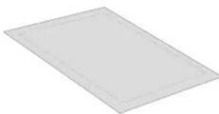
natural_image
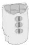
Blank rectangular paper or panel with no visible text, symbols, or markingsPlaymat (1)
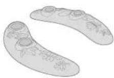
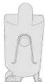
Feet (2)
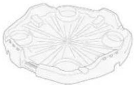
natural_image
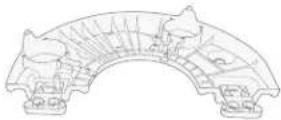
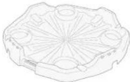
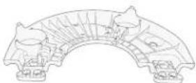
Line drawing of a mechanical component with symmetrical cutouts and radial lines (no text or symbols)Base (1)
Tray Half (2)
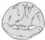
Seat Pad (1)
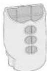
Lower Leg (4)
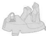
Lower Leg Pedestal (4)
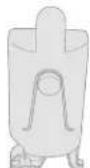
Upper Leg (4)
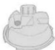
Upper Leg Crown (4)
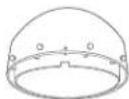
Seat Ring (1)
Hardware Kit Bag (1)
1 Instructions
24 Screws—#6x3/4"(3.5 x 19 mm)
4 Washers
4 Large springs
4 1-3/4" (44.5 mm) springs
4 1-1/2" (38 mm) springs
2 End Caps
4 Leg Locks
4 Pylon Rings
4 Stabilizer Feet
6 Seat Wheels
Toy Kit Bag (1)
8 Toys
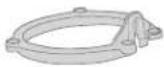
Pylon Ring (4)
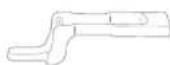
Leg Lock (4)
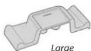
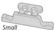
End Caps (2)
Tools Required

Phillips Screwdriver
CAUTION: Tighten all screws until snug; do not overtighten. Use only #6 x 3/4" (3.5 x 19 mm) screws (included). DO NOT USE POWER TOOLS.
Registration Information
Please register this product so we can reach you if there is a safety alert or recall. We will not sell, rent, or share your personal information. To register your product, please complete and mail the card that came with it or visit our online registration at
www.evenflo.com/registerproduct
For future reference, record the Model Number and Date of Manufacture below.
Model Number: Date of Manufacture:
ParentLink.
answers, advice, affirmation.
- www.evenflo.com • USA: 1-800-233-5921, 8 AM - 5PM E.T.
• Canada: 1-937-773-3971 • México: 01-800-706-12-00
WARNING
READ AND FOLLOW ALL WARNINGS AND INSTRUCTIONS! FAILURE TO DO SO COULD RESULT IN SERIOUS INJURY OR DEATH!
- NEVER leave child unattended. ALWAYS keep child in view while in the ExerSaucer®.
- Read all instructions before assembly and use of the ExerSaucer®.
- Keep instructions for future use.
- Keep children away from unassembled product.
- Adult assembly required. Take care when unpacking and assembling; contains small parts and sharp edges.
• To prevent a possible choking hazard, remove and immediately discard packing material before using this product. -
Strings Can Cause Strangulation!
-
DO NOT place the ExerSaucer® anywhere near cords from window blinds, draperies, phone, etc.
- DO NOT place items with strings, such as hood strings or pacifier cords, around your child's neck.
• DO NOT suspend strings over product or attach strings to toys.
- To avoid possible entanglement or strangulation (on Stage 1), remove toy bar when baby begins to push up on hands and knees.
• NEVER use near stairs or steps.
- NEVER use ExerSaucer® near ranges, radiators, space heaters, fireplaces or any other heat source.
- NEVER use ExerSaucer® in or near swimming pools or other bodies of water.
- DO NOT fill the ExerSaucer® tray with water.
- DO NOT fold or adjust height while baby is sitting in ExerSaucer®.
- DO NOT use the ExerSaucer® if any parts are missing, damaged or broken.
• NEVER use as a sled.
- DO NOT allow child to sleep in ExerSaucer® (Stage 2).
- DO NOT spin baby in seat. Only permit baby to rotate the seat.
- Stage 2 is for use by children who are at least 4 months old AND can hold up their head and neck unassisted.
- Stop using Stage 2 when your child reaches any of the following developmental stages:
- Can walk by himself/herself
• Is over 30" (76 cm) tall - Can climb out of the product
- Can stand flat-footed in the ExerSaucer® in the highest adjustment level
- Allow only the baby's toes to touch the base. DO NOT allow the baby to stand flat-footed on the base.
• DO NOT use or store this product outdoors.
- To avoid tip-over, place product on flat, level floor.
- NEVER place playmat from Stage 1 in the bottom of saucer.
• DO NOT mix old and new batteries.
- DO NOT mix alkaline, standard (carbon-zinc), or rechargeable (nickel-cadmium) batteries. Only batteries of the same or equivalent type, as recommended, are to be used.
- DO NOT dispose of batteries in fire, as batteries may explode or leak.
- DO NOT use rechargeable batteries.
- DO NOT recharge non-rechargeable batteries.
- Promptly remove old batteries from the toy.
- Remove batteries before storing unit for a prolonged period of time.
Stage 1
Stage 1 is used for infants from birth to 4 months old.
Stage 1
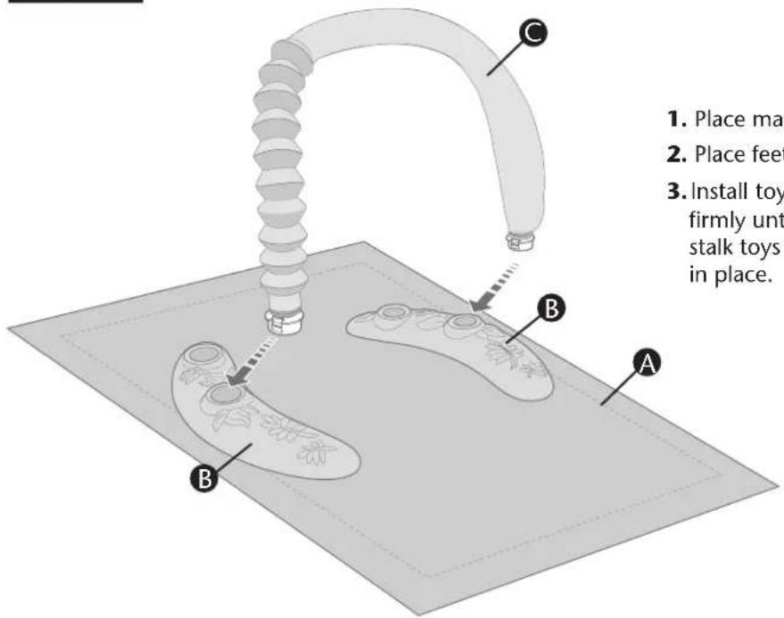
- Place mat A on floor.
- Place feet Ⓑ on either side of mat, as shown.
- Install toy bar Ⓐ into feet, as shown. Press toy bar down firmly until it snaps into place. Pull up on the toy bar and stalk toys installed into the feet to make sure they are locked in place.
Stage 2
Stage 2 is used for infants 4 months old (who can hold up head and neck unassisted) to walking age and under 30 inches tall.
Stage 2
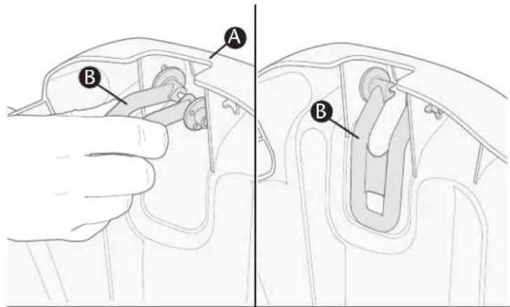
- Turn base A upside down and locate four stabilizer feet B. Insert one side of foot B into the foot bracket hole and twist the foot until the other side snaps into the opposite hole, as shown. Repeat until all four stabilizer feet are installed.
To use stabilizer feet:
Flip the four stabilizer feet out from beneath base to prevent ExerSaucer ^® from rocking.
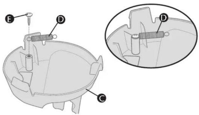
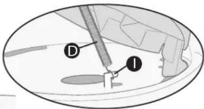
- Locate four pedestals Ⓐ, then turn over and install the 1-1/2 inch (38 mm) spring Ⓓ with screw Ⓔ in each pedestal. Position spring as shown. Do not overtighten screw.
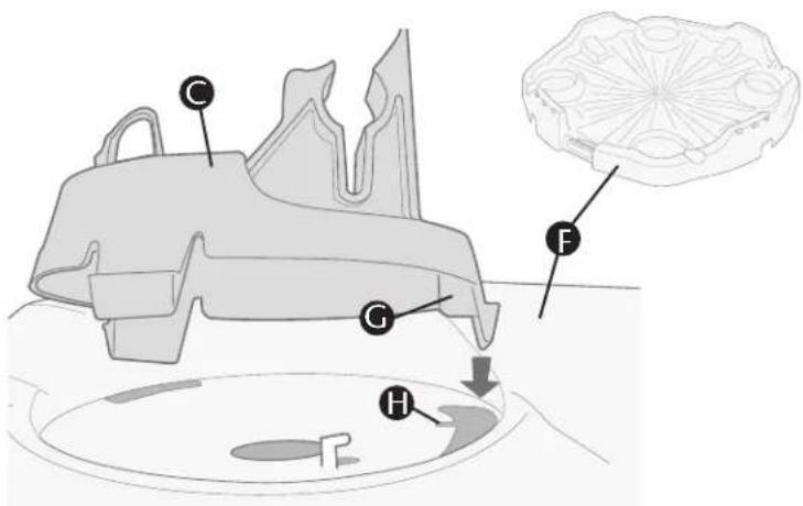
- To install a pedestal C, hold it above the base F so that the locking tab with the rib G lines up directly over the slot with the notch H.
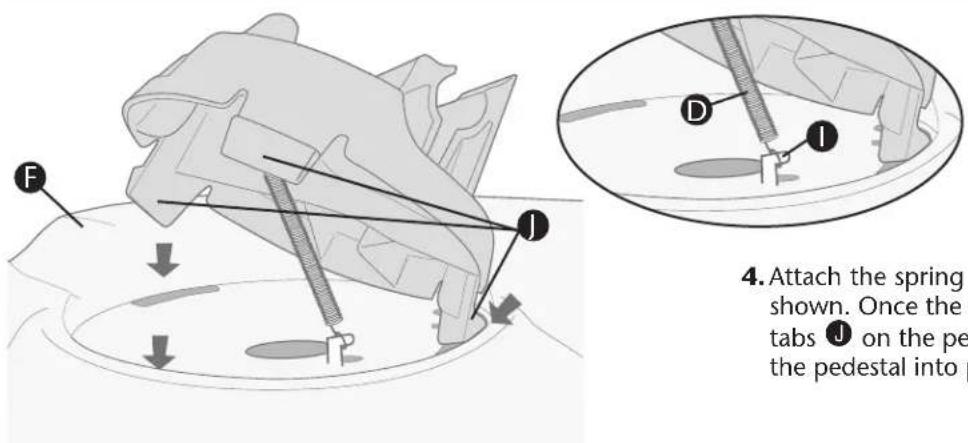
- Attach the spring Ⓓ to the hook ⏻ on the base Ⓔ, as shown. Once the spring is in place, align all three locking tabs ⚠ on the pedestal with the slots in the base and snap the pedestal into place.
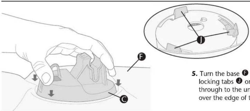
- Turn the base Ⓕ upside down and make sure the locking tabs ⚠ on each pedestal Ⓞ are completely pushed through to the underside of the base Ⓕ and have locked over the edge of the openings, as shown.
natural_image
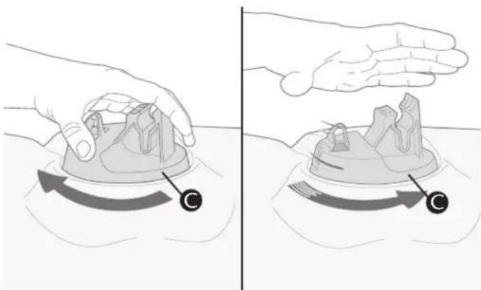
Illustration showing two hand positions (left and right) of a dental implant or implant device, with no visible text or symbols.- Check to ensure that the locking tabs are installed properly by turning the pedestal Ⓐ clockwise, then releasing. The pedestal MUST spring back into place. Repeat for all four pedestals.
Stage 2 Base Assembly
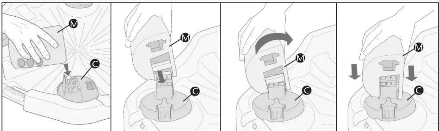
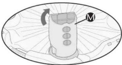
- Insert lower leg assembly Ⓜ at an angle (as shown) onto top of pedestal Ⓐ, then rock gently while applying a steady downward pressure until it snaps into place. Swing lower leg assembly Ⓜ up until it locks in the upright position. Repeat for all four leg assemblies. You are now finished assembling the base. Set it aside so you can assemble the tray.
Stage 2 Tray Assembly
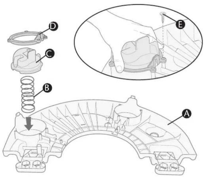
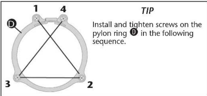
- Locate two tray halves A. Install spring B, upper leg crown C, and pylon ring D onto one of the tray halves. Secure with four screws E. Note: Hold the upper leg crown C and pylon ring D securely while installing screws. Tension from the spring will try to push the upper leg crown and pylon ring upward. Repeat for other upper leg crown on this tray and for both upper leg crowns on the other tray half.
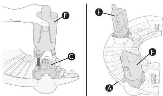
- Insert upper leg F into the upper leg crown C until it snaps into place. Pull up on upper leg F to ensure it is securely installed in upper leg crown C. Repeat until all four upper leg assemblies are complete. Note: Make sure the adjustment holes on the front of all four upper legs F are facing the outer edge of the tray A, as shown.
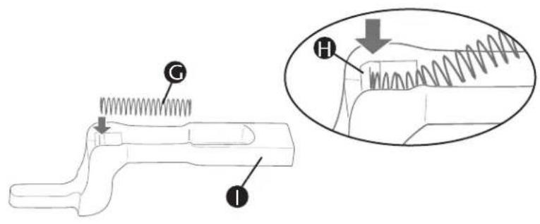
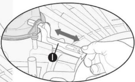
- Slide one end of 1-3/4 inch (44.5 mm) spring G into the spring notch H in leg lock I, as shown.
Note: Once the spring has been installed correctly, it will stay in place. Repeat for all four leg locks.
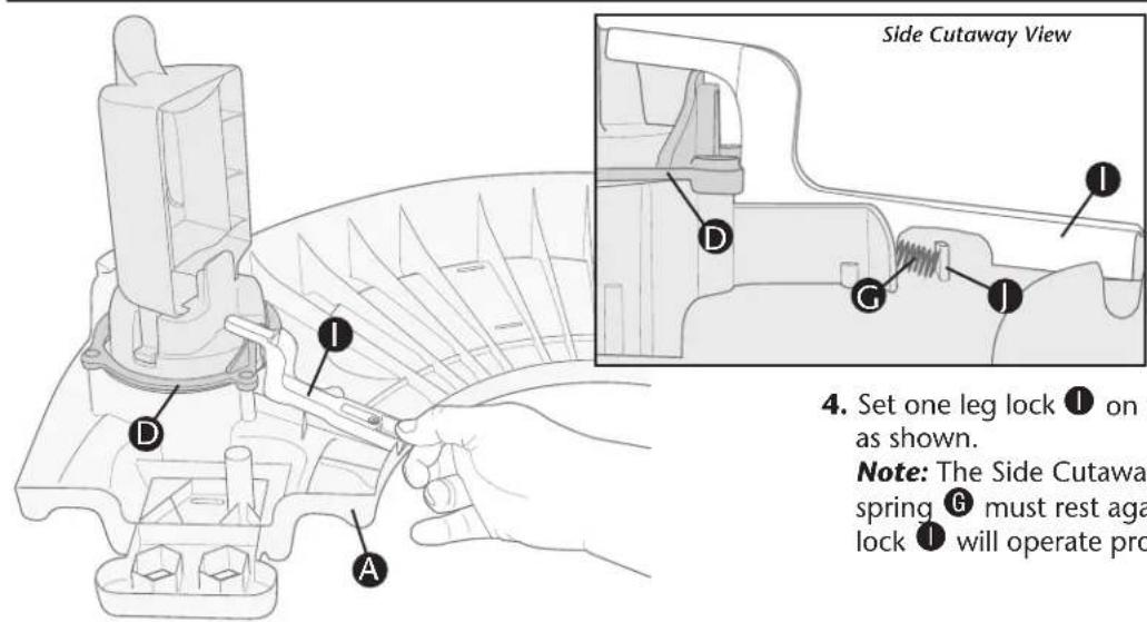
- Set one leg lock ⏱ on the pylon ring Ⓓ and on the tray Ⓔ, as shown.
Note: The Side Cutaway View above illustrates how the spring Ⓖ must rest against the spring tab ⚠ so the leg lock ⚣ will operate properly.
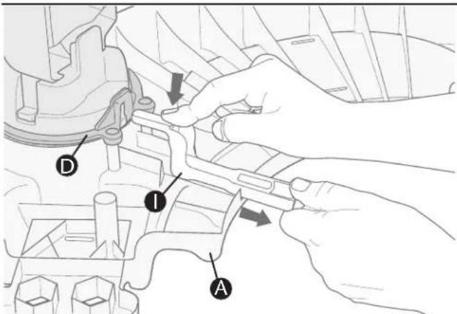
- Push downward on the leg lock ⏻ (against the pylon ring Ⓓ and the tray ⚠) while pulling it toward you until it slides off of the pylon ring, as shown.
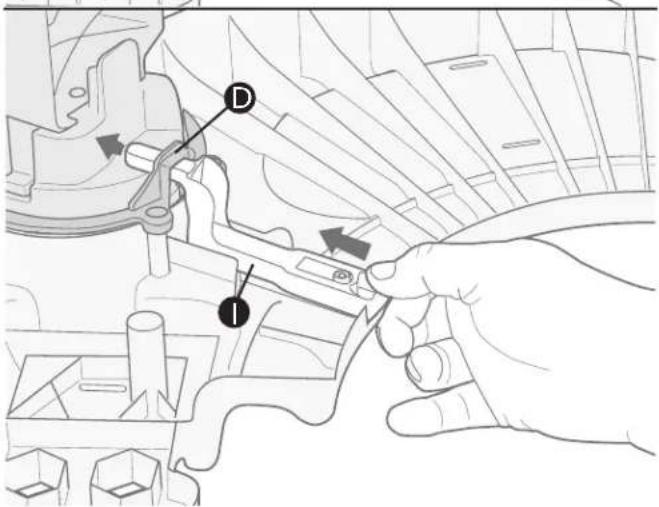
- While holding the leg lock ⏻, allow the spring to pull the leg lock back toward the upper leg as you guide it through the pylon ring Ⓓ, as shown.
Stage 2 Tray Assembly
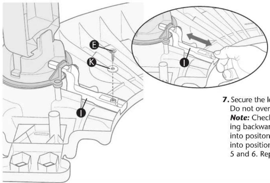
- Secure the leg lock ⏻ with screw Ⓔ and washer Ⓙ. Do not overtighten.
Note: Check that each leg lock is installed correctly by pulling backward, then releasing it. If the leg lock springs back into positon, it is installed correctly. If it does not spring back into position, remove the screw and washer and repeat Steps 5 and 6. Repeat for all legs.
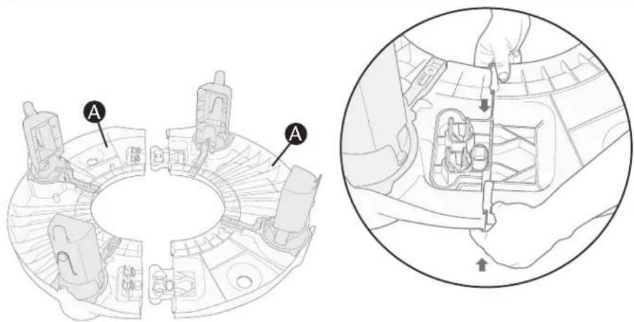
- Assemble the tray by snapping both tray halves Ⓐ together, as shown. Note: Make sure the tray halves lock securely.
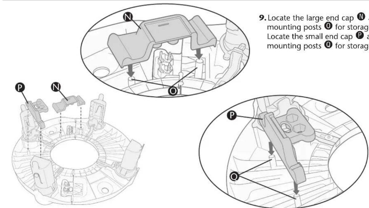
- Locate the large end cap N and press it onto mounting posts O for storage, as shown. Locate the small end cap P and press it onto mounting posts Q for storage, as shown.
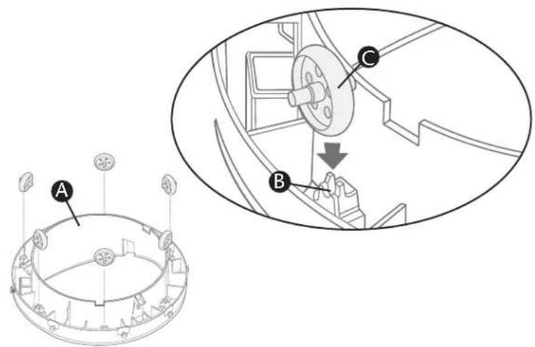
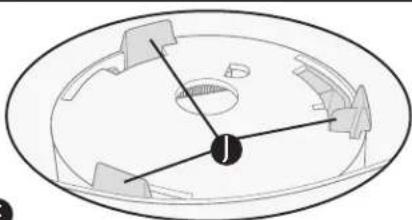
- Place seat ring Ⓐ upside down and locate the wheel holders Ⓑ. Snap six (6) seat wheels Ⓓ into wheel holders, as shown.
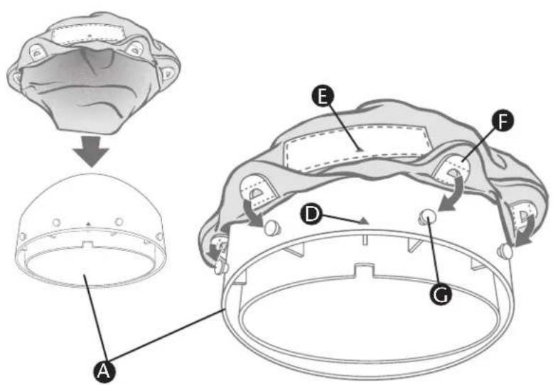
- Turn seat ring A right side up. Align triangle D on the back of the seat ring with the triangle E on the seat pad label. Snap the plastic tabs F on the pad over the pegs G on the seat ring. Continue this process until all tabs are attached to all pegs.
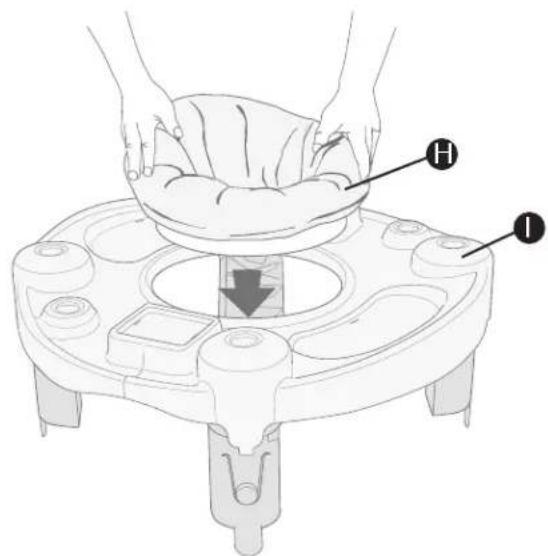
- Press assembled seat ring Ⓗ down firmly onto the top of the tray ⏻ until it snaps into place and spins freely.
Stage 2 Seat Assembly
natural_image
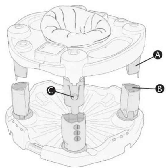
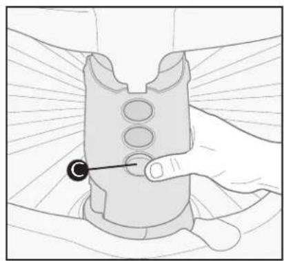
Illustration of a hand holding a device with a circular button and pointer (no text or symbols)Align and start each upper leg A into the lower leg openings B. Push button C and guide upper leg into lower leg until upper leg snaps into place.
WARNING
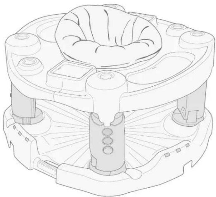
Allow only the baby's toes to touch the base. DO NOT allow the baby to stand flat-footed on the base. As baby grows and becomes more active, raise the tray to the next level so that baby enjoys the most comfortable fit and maximum use of the spin and bounce features.
natural_image
Technical line drawing of a mechanical device with no visible text or symbolsTo adjust height:
ALWAYS remove baby from ExerSaucer® before adjusting. Push the button Ⓐ until the desired position is obtained. Make sure that all four legs are adjusted to the same position.
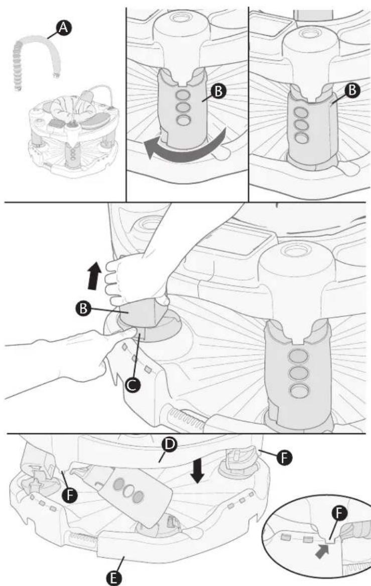
- To fold ExerSaucer®, ALWAYS remove baby and toy bar(s) A from ExerSaucer® before folding.
With ExerSaucer ^® flat on the floor, twist each leg assembly ^® fully clockwise (the direction of the arrow) until it stops in the position shown.
Fully depress one of the pedestal locking tabs ⑥ then push on the leg assembly ⑧; leg will partially fold. Repeat this procedure for all four legs.
After pressing the fourth pedestal locking tab Ⓓ, the ExerSaucer® will fold with the tray Ⓓ rotating toward the base Ⓔ. Make sure all four tray locks Ⓕ are locked onto the base before trying to carry ExerSaucer®.
Note: Make sure the legs are at the same height adjustment or the ExerSaucer® will bind and not fold properly (refer to page 8).
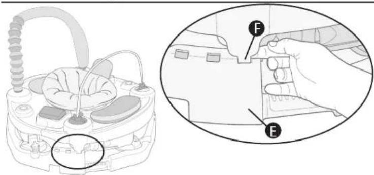
- To unfold the ExerSaucer®, release the four tray locks F by pulling them outward from the base E, as shown.
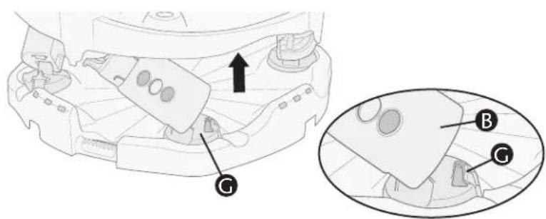
Hold the base down with your foot, and pull the tray upward. The tray will rotate as you pull and the legs will lock in the upright position. The leg assemblies Ⓑ will lock onto the pedestals Ⓐ.
Twist the tray to make sure all legs are locked properly. IMPORTANT: Make sure all four leg assemblies Ⓑ are firmly locked onto the pedestals Ⓐ before use.
Stage 3
Stage 3 is used for children who are walking age to 24 months.
Stage 3
IMPORTANT: Child should not use the activity table if they can not stand up by themselves.
-
Remove toys and seat from the ExerSaucer®.
-
Follow Step 1 on page 10 to fold the ExerSaucer ^® , but do not let the tray lock to the base.
-
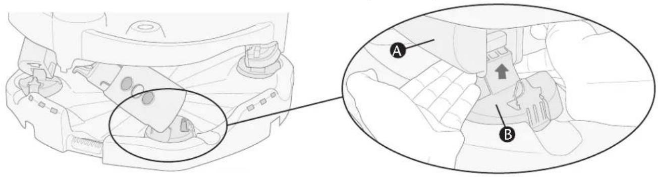
Place your fingers beneath the legs Ⓐ, as shown, and push upward to disconnect the leg assemblies from the pedestals Ⓑ. Repeat for all four leg assemblies.
-
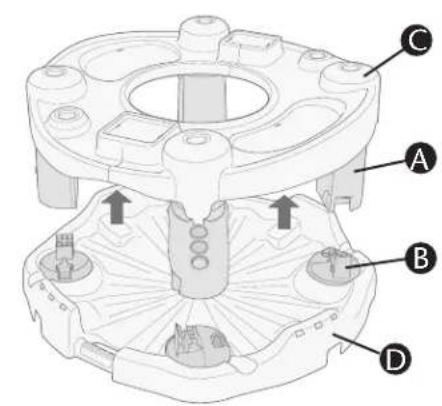
After all four legs have been disconnected from the pedestals, remove tray assembly C from the base D.
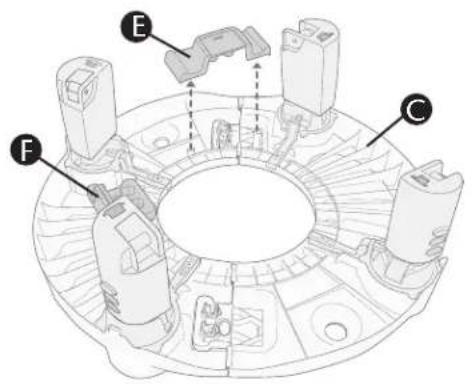
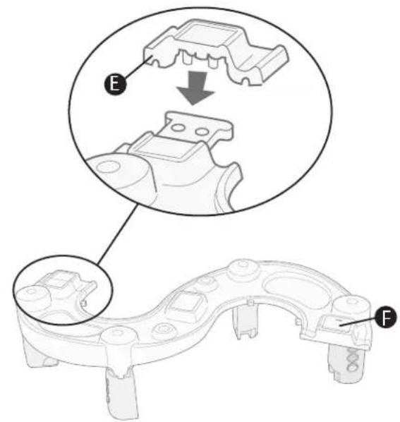
- Turn tray C upside down and remove the large end cap E and the small end cap F from beneath.
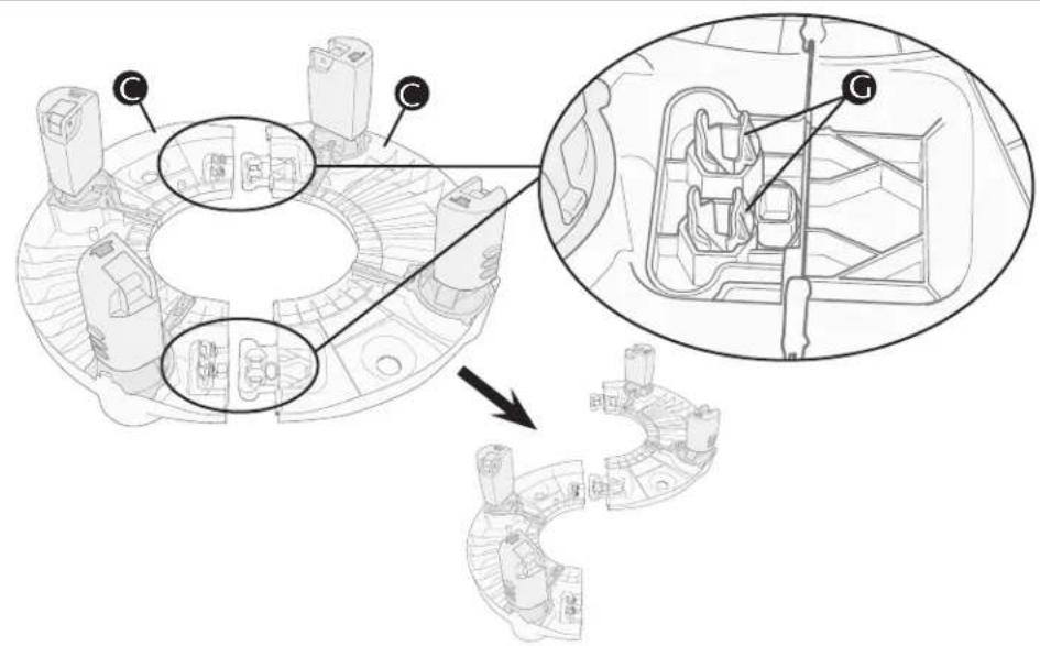
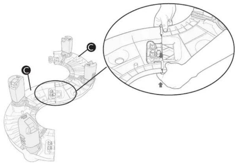
- Squeeze both locking tabs Ⓖ on each side of the tray to disconnect and separate the tray halves Ⓔ. Re-position them as shown.
Stage 3 Assembly
- Connect tray halves Ⓐ to form activity table. Note: Make sure the tray halves lock securely.
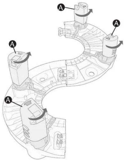
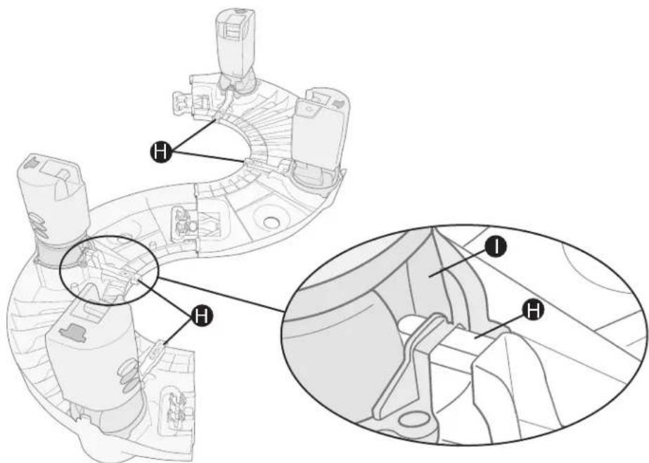
- Rotate leg assemblies Ⓐ fully counterclockwise, (the direction of the arrow) until they lock into the position shown. Make sure that all four leg locks Ⓗ are locked properly into the upper leg crown ⏻, as shown above. Also, make sure the ends of all four leg locks Ⓗ are sticking out past the edge of the tray, as shown.
IMPORTANT: DO NOT use this activity table unless the legs have locked into place!
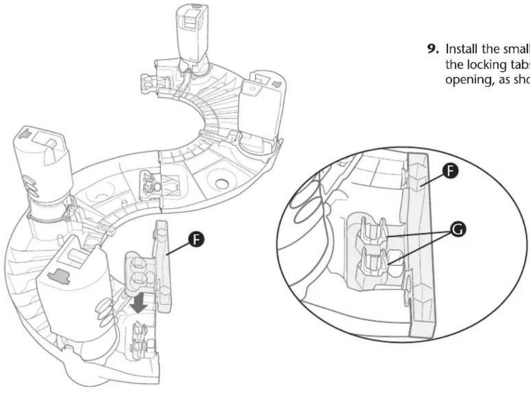
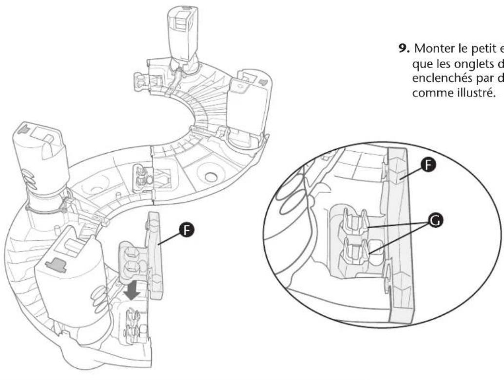
- Install the small end cap F, as shown. Make sure the locking tabs G have locked over the edge of the opening, as shown.
-
Turn table over and install the large end cap Ⓔ, as shown. Make sure both end caps Ⓔ and Ⓕ are locked into place.
-
Install toys on activity table. If desired, adjust table to the appropriate height (page 8) for your child.
Note: Always make sure that all four legs are adjusted to the same height.
IMPORTANT: NEVER use Stage 3 without end caps!

natural_image
Technical line drawing of a mechanical device with coiled spring and two ports (no text or symbols)For Plastic Parts:
Wipe surface clean with cloth slightly moistened with mild soap and water. Allow to air dry.
For Seat Pad and Playmat:
For Best Results
Machine Wash Separately, Cold Water – Delicate Cycle. NO CHLORINE BLEACH.
Tumble Dry: 10 – 15 Minutes on Low Heat – Remove Immediately.
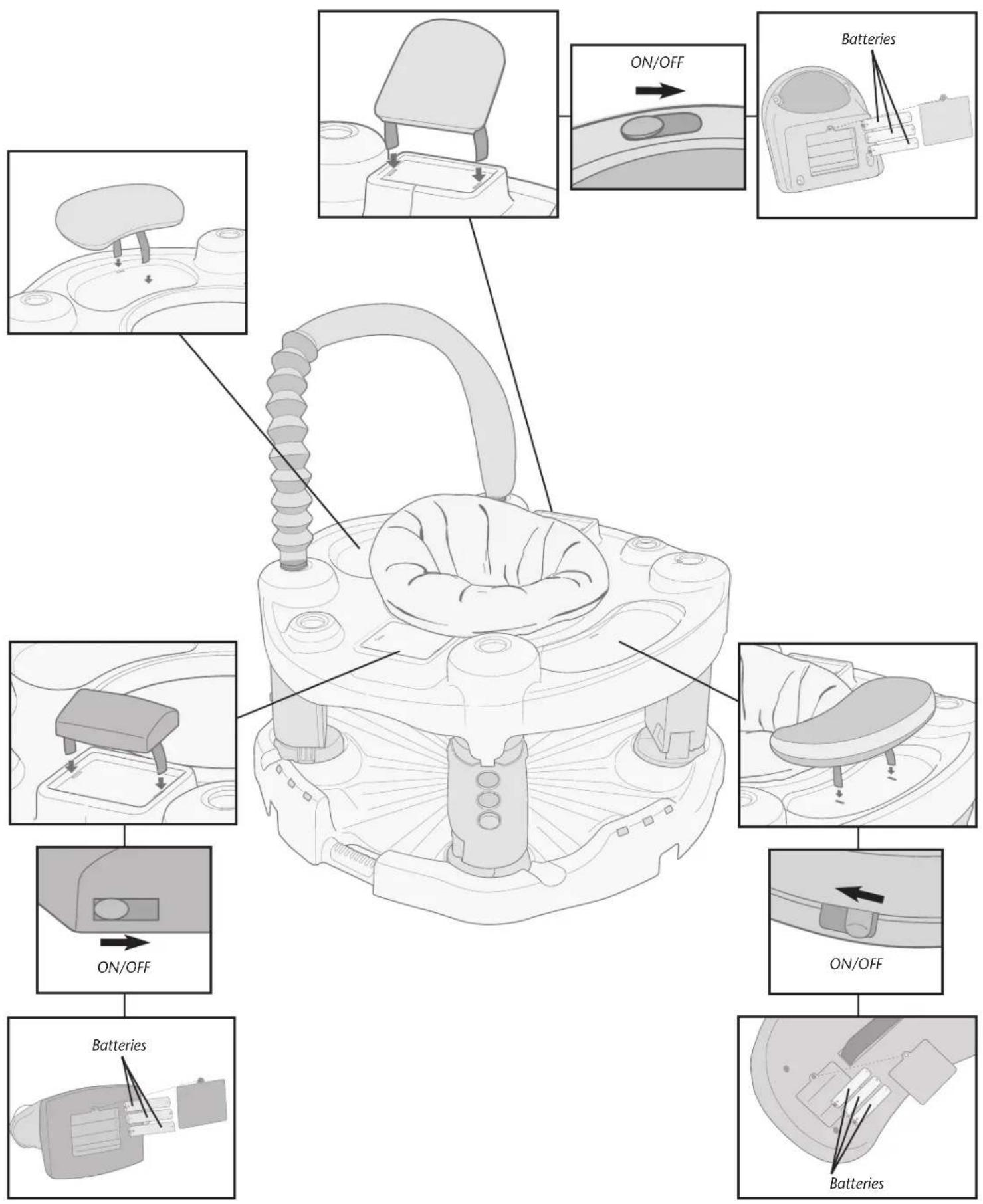
If musical toys fail to operate, check the batteries. Note: ONLY the AAA batteries are replaceable. Dispose of old batteries safely.
DO NOT use this product if any parts are missing, damaged or broken.
BATTERY INFORMATION
Battery life varies with use.
Safety Information: Batteries are small objects. Batteries must be replaced by adults. Follow the polarity (+/-) diagram in the battery compartment.
WARNING
• DO NOT mix old and new batteries.
- DO NOT mix alkaline, standard (carbon-zinc), or rechargeable (nickel-cadmium) batteries.
- Remove batteries before storing unit for a prolonged period of time.
• DO NOT allow unit to get wet.
- Promptly remove dead batteries from the toy.
- Dispose of used batteries properly.
- Only batteries of the same or equivalent type, as recommended, are to be used.
- DO NOT dispose of batteries in fire, as batteries may explode or leak.
• DO NOT use rechargeable batteries.
- DO NOT recharge non-rechargeable batteries.
Battery Replacement: To replace batteries, loosen screw and remove battery door. Discard old batteries properly and replace with 3 AAA alkaline batteries. Replace door and tighten screw.
Troubleshooting:
Toy does not turn on or does not respond.
- Make sure batteries are installed correctly.
- Make sure battery cover is correctly secured.
• Install new batteries.
Toy makes improper responses.
- Check or install new batteries.
- Power Off then Power On, to reset.
For a period of 90 days from the original purchase of this Product, Evenflo warrants to the original end user ("Purchaser") this Product (including any accessories) against defects in material or workmanship. Evenflo's sole obligation under this express limited warranty shall be, at Evenflo's option, to repair or replace any Product that is determined to be defective by Evenflo and determined to be covered by this warranty.
Repair or replacement as provided under this warranty is the exclusive remedy of the Purchaser. Proof of purchase in the form of a receipted invoice or bill of sale evidencing that the Product is within the warranty period must be presented to obtain warranty service. This express limited warranty is extended by Evenflo ONLY to the original Purchaser of the Product and is not assignable or transferable to subsequent purchasers or end users of the Product. For warranty service, contact Evenflo's ParentLink Consumer Resource Center at (800) 233-5921 or www.evenflo.com.
EXCEPT TO THE EXTENT PROHIBITED BY APPLICABLE LAW, ANY IMPLIED WARRANTY OF MERCHANTABILITY OR FITNESS FOR A PARTICULAR PURPOSE ON THIS PRODUCT IS HEREBY DISCLAIMED. EVENFLO SHALL NOT BE LIABLE FOR ANY INCIDENTAL, CONSEQUENTIAL, SPECIAL OR PUNITIVE DAMAGES OF ANY KIND FOR BREACH OF THE EXPRESS LIMITED WARRANTY ON THIS PRODUCT, OR ANY WARRANTY IMPLIED BY OPERATION OF LAW. OTHER THAN THE EXPRESS LIMITED WARRANTY SET FORTH ABOVE, THERE ARE NO OTHER WARRANTIES THAT ACCOMPANY THIS PRODUCT AND ANY ORAL, WRITTEN OR ANY OTHER EXPRESS REPRESENTATION OF ANY KIND IS HEREBY DISCLAIMED.
For Australian Consumers
For consumers' transactions in Australia, the limited warranty terms contained in the above statements, except to the extent lawfully permitted, do not exclude, restrict, or modify but are in addition to any mandatory statutory rights. For Australian consumers, our goods come with guarantees that cannot be excluded under Australian Consumer Law. You are entitled to a replacement or refund for a major failure and for compensation for any other reasonably foreseeable loss or damage. You are also entitled to have the goods repaired or replaced if the goods fail to be of acceptable quality and the failure does not amount to a major failure.
This device complies with Part 15 of the FCC Rules. Operation is subject to the following two conditions: (1) this device may not cause harmful interference, and (2) this device must accept any interference received, including interference that may cause undesired operation.
WARNING
Changes or modifications to this unit not expressly approved by the party responsible for compliance could void the user's authority to operate the equipment.
Note: This equipment has been tested and found to comply with the limits for a Class B digital device, pursuant to Part 15 of the FCC Rules. These limits are designed to provide reasonable protection against harmful interference in a residential installation. This equipment generates, uses, and can radiate radio frequency energy and, if not installed and used in accordance with the instructions, may cause harmful interference to radio communications. However, there is no guarantee that interference will not occur in a particular installation. If this equipment does cause harmful interference to radio or television reception, which can be determined by turning the equipment off and on, the user is encouraged to try to correct the interference by one or more of the following measures:
- Reorient or relocate the receiving antenna.
- Increase the separation between the equipment and receiver.
- Connect the equipment into an outlet on a circuit different from that to which the receiver is connected.
- Consult the dealer or an experienced radio TV technician for help.
- This Class B digital apparatus complies with Canadian ICES-003.
ParentLink.
answers. advice. affirmation."
- www.evenflo.com • USA: 1-800-233-5921 8 AM – 5 PM E.T.
- Canada: 1-937-773-3971 • México: 01-800-706-12-00
Table des matières
natural_image
Blank rectangular paper or sheet with no visible text, symbols, or markingsTapis de jeu (1)
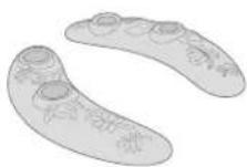
Pied (2)
natural_image
Technical line drawing of a mechanical component with symmetrical cutouts and radial grooves (no text or symbols)Base (1)
answers, advice, affirmation.™
• www.evenflo.com • USA: 1-800-233-5921, 8 AM – 5PM E.T.
- Canada: 1-937-773-3971 - México: 01-800-706-12-00
AVERTISSEMENT
LIRE ET SUIVRE TOUS LES AVERTISSEMENTS ET INSTRUCTIONS ! SINON CELA POURRAIT ÊTRE SOURCE DE BLESSURES GRAVES VOIRE MORTELLES !
natural_image
Illustration showing two hand positions on a device with a circular component, no text or symbols presentnatural_image
Diagram of a mechanical component with directional arrow and label M, no readable text or symbols present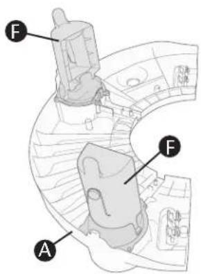

natural_image
Diagram of hands adjusting a mechanical component inside a vehicle (no text or symbols visible)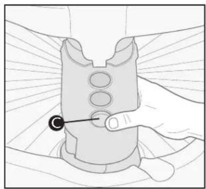
natural_image
Illustration of a hand holding a mechanical component with a circular button and pointer (no text or symbols)natural_image
Technical line drawing of a mechanical component with no visible text or symbols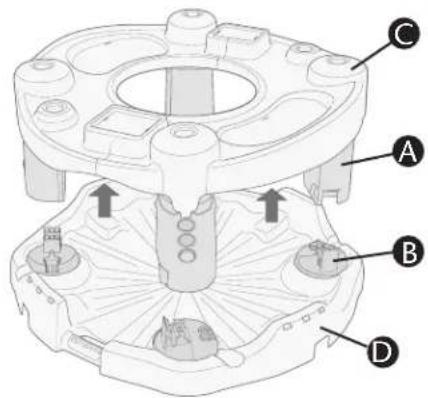
natural_image
Technical line drawing of a mechanical device with coiled spring and two ports (no text or symbols)answers. advice. affirmation.™
- www.evenflo.com • USA: 1-800-233-5921 8 AM – 5 PM E.T.
- Canada: 1-937-773-3971 • México: 01-800-706-12-00
Índice
Advertencias 33
natural_image
Blank rectangular paper or panel with no visible text, symbols, or markingsManta de actividades (1)
Pata inferior (4)
natural_image
Technical line drawing of a mechanical component with symmetrical cutouts and central hub (no text or symbols)Base (1)
Pata superior
(4)
Mitad de la charola (2)
answers. advice. affirmation.
• www.evenflo.com • USA: 1-800-233-5921 8 AM a 5 PM hora del Este
• Canada: 1-937-773-3971 • México: 01-800-706-12-00
ADVERTENCIA
natural_image
Diagram of a circular mechanical component with internal features and a central hole (no text or symbols)natural_image
Illustration showing two hand positions on a device with a circular component, no text or symbols present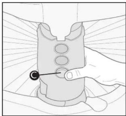
natural_image
Illustration of a hand holding a mechanical component with a circular feature, no text or symbols presentnatural_image
Technical line drawing of a mechanical device with no visible text or symbols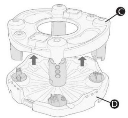
natural_image
Technical diagram of a mechanical assembly with labeled components (C, D) and directional arrows indicating movement or force (no text or symbols beyond labels)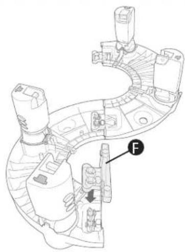
natural_image
Technical line drawing of a mechanical assembly with labeled component 'F' (no text or symbols beyond label)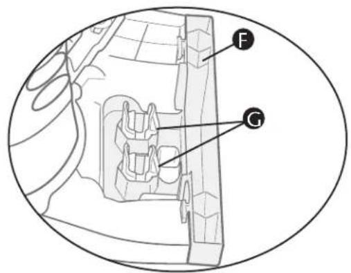
natural_image
Technical line drawing of a mechanical device with hoses and connectors (no text or symbols)answers. advice. affirmation.™
- www.evenflo.com • USA: 1-800-233-5921 8 AM a 5 PM hora del Este
• México: 01-800-706-12-00
ParentLink.
answers. advice. affirmation."
- Hardware Kit Bag (1)
- Tools Required
- Phillips Screwdriver
- Registration Information
- WARNING
- READ AND FOLLOW ALL WARNINGS AND INSTRUCTIONS! FAILURE TO DO SO COULD RESULT IN SERIOUS INJURY OR DEATH!
- Stage 1
- Stage 1 is used for infants from birth to 4 months old.
- Stage 2
- Stage 2 is used for infants 4 months old (who can hold up head and neck unassisted) to walking age and under 30 inches tall.
- To use stabilizer feet:
- To adjust height:
- Stage 3
- Stage 3 is used for children who are walking age to 24 months.
- For Plastic Parts:
- For Seat Pad and Playmat:
- BATTERY INFORMATION
- Troubleshooting:
- For Australian Consumers
- ParentLink.
- AVERTISSEMENT
- LIRE ET SUIVRE TOUS LES AVERTISSEMENTS ET INSTRUCTIONS ! SINON CELA POURRAIT ÊTRE SOURCE DE BLESSURES GRAVES VOIRE MORTELLES !
- Índice
- ADVERTENCIA
Brand : Evenflo
Model : Exersaucer Life In The Amazon Triple Fun
Category : Baby products