
MasterFlush MF 8989 - Toilet DOMETIC - Free user manual and instructions
Find the device manual for free MasterFlush MF 8989 DOMETIC in PDF.


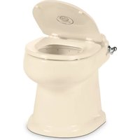
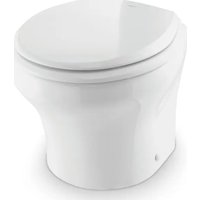
| Product Type | Toilet with macerator pump |
| Brand | Dometic |
| Model | MasterFlush MF 8989 |
| Category | Toilet |
| Dimensions (H x W x D) | 851 x 375 x 473 mm |
| Bowl material | Vitreous ceramic |
| Pump body material | Glass-reinforced polypropylene |
| Control box material | ABS plastic |
| Power supply | 12/24 V DC |
| Rated current | 20 A (12 V) / 15 A (24 V) |
| Recommended wire size | Tinned stranded copper, 12 AWG minimum |
| Flush type | Macerator pump |
| Water inlet | NPT 1/2" fitting, 13 mm inner diameter, min. flow 7.6 L/min |
| Discharge | 38 mm or 25 mm diameter, max horizontal length 30 m, vertical 3 m |
| Water temperature | Cold water only |
| Main functions | Electric flush, waste grinding, optional full tank shut-off, optional level controller |
| Safety | Integrated fuse, shut-off valve required, vented loop for raw water, power cut before maintenance |
| Installation | Floor mounting or through-wall, template provided |
| Maintenance and cleaning | Cleaning with non-abrasive products, regularly check fittings and clamps |
| Supplied parts | Bowl, DFT touch pad, control module, cables, discharge adapters, mounting hardware |
| Optional accessories | Level controller DTM01C (1 level) or DTM04 (4 levels) |
| Standards | Complies with ANSI/NFPA 70, ANSI/NFPA 1192, ABYC, CSA C22.1, CSA Z240 RV |
| Customer service | Tel. 1-800-321-9886 (USA/Canada), www.dometic.com |
Frequently Asked Questions - MasterFlush MF 8989 DOMETIC
User questions about MasterFlush MF 8989 DOMETIC
0 question about this device. Answer the ones you know or ask your own.
Ask a new question about this device
Download the instructions for your Toilet in PDF format for free! Find your manual MasterFlush MF 8989 - DOMETIC and take your electronic device back in hand. On this page are published all the documents necessary for the use of your device. MasterFlush MF 8989 by DOMETIC.
USER MANUAL MasterFlush MF 8989 DOMETIC
Service Center & Dealer Locations
Refer to "8 Customer Service" on page 16
Read these instructions carefully. These instructions MUST stay with this product.
CONTENTS
1 Explanation of symbols and safety instructions. 3
2 General information....4
3 Intended use 5
4 Specifications.... 5
5 Prepare for installation....8
6 Installation 10
7 Disposal 16
8 Customer Service....16
1 EXPLANATION OF SYMBOLS AND SAFETY INSTRUCTIONS
This manual has safety information and instructions to help you eliminate or reduce the risk of accidents and injuries.
1.1 Recognize safety information

This is the safety alert symbol. It is used to alert you to potential physical injury hazards. Obey all safety messages that follow this symbol to avoid possible injury or death.
1.2 Understand signal words
A signal word will identify safety messages and property damage messages, and will indicate the degree or level of hazard seriousness.
WARNING serious injury.
indicates a hazardous situation that, if not avoided, could result in death or
CAUTION moderate injury
indicates a hazardous situation that, if not avoided, could result in minor or
NOTICE
is used to address practices not related to physical injury.

indicates additional information that is not related to physical injury.
1.3 Supplemental directives

Read and follow all safety information and instructions to avoid possible injury or death. Read and understand these instructions before installation of this product. Incorrect installation of this product can lead to serious injury.
The installation must comply with all applicable local or national codes, including the latest edition of the following standards:
U.S.A.
• ANSI/NFPA70, National Electrical Code (NEC)
• ANSI/NFPA 1192, Recreational Vehicles Code
• ABYC guidelines for marine installations
Canada
• CSA C22.1, Parts I & II, Canadian Electrical Code
• CSA Z240 RV Series, Recreational Vehicles
1.4 General safety messages
WARNING
Failure to obey the following warnings could result in property damage, serious
- This product must be installed and serviced by a qualified service technician.
- Do not modify this product in any way. Modifi cation can be extremely hazardous.
- FLOOD HAZARD:
- Seacocks must be installed in all piping connected to through-the-hull fittings. Seacocks must be easily accessible to all users of the toilet, or secondary valves should be fitted in hose runs where they are easily accessible.
- If the toilet is connected to any through-the-hull fittings: always close seacocks when toilet is not in use (even if the boat is unattended for a brief period).
-
Valves must be full-bore valves of marine sanitation quality. Do not use screw-to-close gate valves.
-
Flexible hoses must be of marine sanitation quality and must be secured to any fittings with two stainless steel, worm-drive, hose-band clamps at each connection. Check connections frequently for integrity.
- Use properly positioned, ventilated loops when the potential exists for the toilet rim to fall below the waterline during any heel, load, or trim condition, or when the toilet is connected to any through-the hull fittings. The ventilated loops must be installed in the intake (if connected to raw water) and/or the discharge piping.
- Ensure that all electrical power to the toilet is turned off and that seacocks are in the closed or off position before installing the toilet or performing any maintenance.
- If the toilet uses fresh water for flushing and is connected directly or indirectly to a shore side municipal water system at any time: shoreside water connections must be discon nected if the boat is unattended (even if boat is unattended for a brief period).
- If the toilet is connected to any through-the-hull fittings: all flexible hoses must be of marine sanitation quality and must be secured to any fittings (such as those at seacock, vented loop or toilet) with two stainless steel, worm-drive hose band clamps at each connection. Connections must be checked frequently for integrity.
- If the toilet uses raw water for flushing at any time, a raw-water pump controlled by an automatically operating demand switch must not be installed. If the onboard water valve or any plumbing connections were to leak, the automatically operated pump would start and could flood the boat.
NOTICE RISK OF PROPERTY DAMAGE. Failure to comply may cause damage to the to or toilet system.
- Only flush water, bodily wastes, and rapid-dissolving toilet tissue.
- Do not overfill the holding tank, or serious damage can occur to the sanitation system. Overfilling the holding tank can rupture the holding tank or release tank contents into the bilge.
2 GENERAL INFORMATION
Included Parts
- Macerator toilet • Dometic Flush Touchpad (DFT) or flush
switch (DFS or DFTS), or other switch options, depending on model
- Control module • Cable for Dometic DFT flush switch or
DSS status panel (RJ45/Ethernet)
- Discharge adapter fittings • Floor-bracket hardware kit
• Floor-mounting template
*For 8700 models only
Optional Parts\*
DTM01C tank monitor
DTM04 four-level tank monitor
* Available as accessory (not included)
3 INTENDED USE
The 8000 Series toilets are designed and intended for use only inside a boat or recreational vehicle (hereinafter referred to as "RV") for which it is supplied. Use the instructions to ensure correct installation of the toilet. Dometic Corporation accepts no liability for damage in the following cases:
- Faulty assembly or connection.
- Damage to the product resulting from mechanical influences and excess voltage.
• Alterations to the product without expressed permission from Dometic Corporation. - Use for purposes other than those described in the operating manual.
Dometic Corporation reserves the right to modify appearances and specifications without notice.
4 SPECIFICATIONS
4.1 Materials
| Component 8100 8500, 8600, 8700, 8900 | |
| Toilet vitreous ceramic | |
| Macerator pump body glass-filled polypropylene | |
| Control module housing — ABS plastic | |
| Dometic DFT switch panel frame — ABS plastic | |
| Dometic DFT switch panel — polycarbonate resin | |
| Dometic flush-switch panel powder-coated aluminum | — |
4.2 Minimum system requirements
8100 8600, 8900 8500, 8700
| Electrical | |||
| Circuit breaker | 20 amps/12 VDC; 15 amps/24 VDC | ||
| Wiring | Marine: Refer to ABYC recommendations.RV: Refer to ANSI/RVIA LV and NFPA 70/NEC Standards for recommended wire gauge (USA). Refer to CEC I and II Standards for recommended wire gauge (Canada). | ||
| Water Supply | |||
| Fitting | 0.5" (13 mm) ID flexible water line | 0.5" (13 mm) NPT | |
| Flow rate | 2.0 gpm/7600 ml/min minimum | 2.5 gpm/9500 ml/min minimum | |
| Discharge | |||
| Inside diameter | 1.5" (38 mm) or 1" (25 mm) | ||
| Horizontal run | 98' (30 m) maximum | ||
| Vertical run | 9.8' (3 m) maximum | ||

Refer to ANSI 1192 and Z240 RV Series standards, where applicable, for additional RV toilet installation guidelines. Specifications are subject to change without notice.
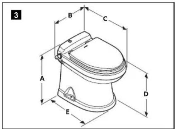
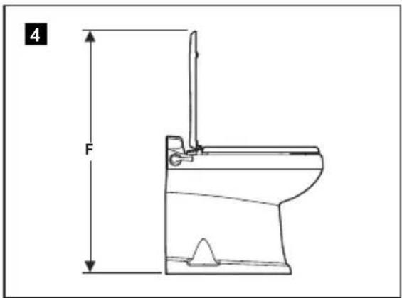
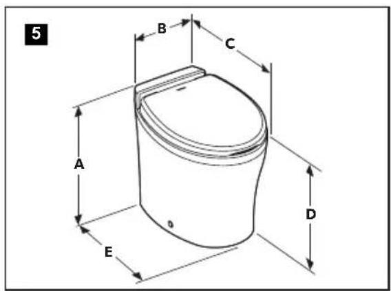
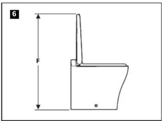
4.3 Dimensions
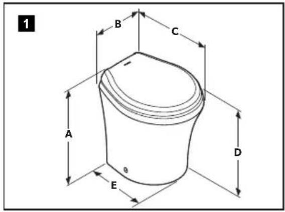
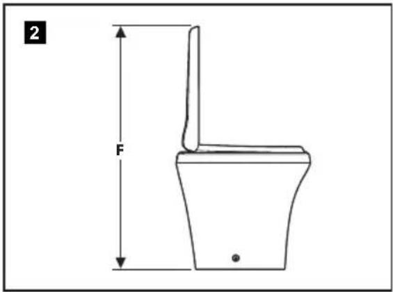
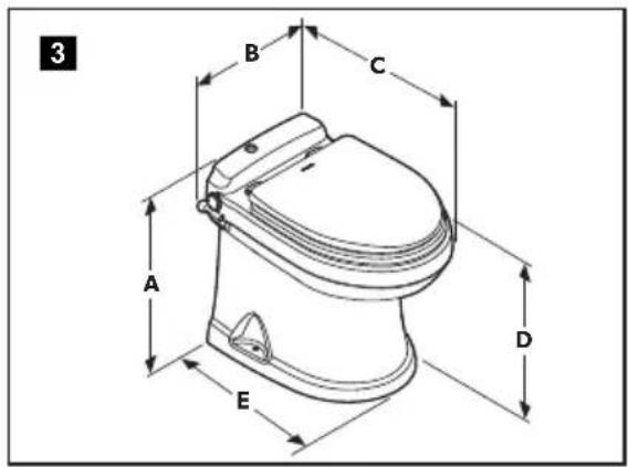
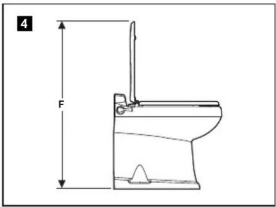
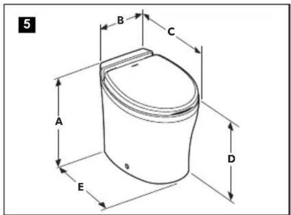
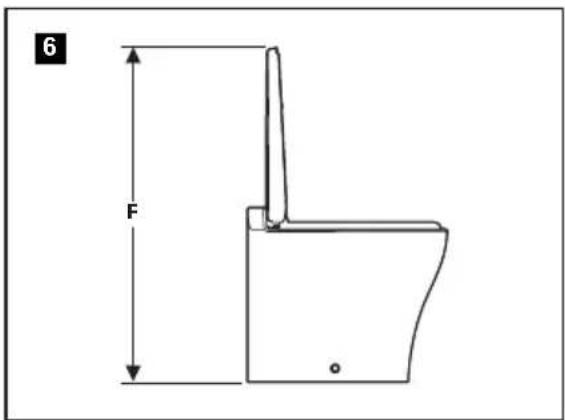
Low-profile dimensions
| Reference | 8100 Series (fig. 1 and 2) | 8600 Series (fig. 1 and 2) | 8900 Series (fig. 1 and 2) |
| A 15" (381 mm) 15" (381 mm) 14.75" (375 mm) | |||
| B 14.75" (375 mm) 14.75" (375 mm) 14.75" (375 mm) | |||
| C 18.375" (467 mm) 19.75" (502 mm) 18.25" (464 mm) | |||
| D 13.75" (349 mm) 14" (356 mm) 13.625" (346 mm) | |||
| E 14" (356 mm) 15.375" (391 mm) 14.875" (378 mm) | |||
| F 28" (711 mm) 30.5" (775 mm) 30.25" (768 mm) | |||
Standard height dimensions
| Reference | 8100 Series (fig. 1 and 2) | 8500 Series (fig. 5 and 6) | 8600 Series (fig. 1 and 2) | 8700 Series (fig. 3 and 4) | 8900 Series (fig. 1 and 2) |
| A 18.375" | (467 mm) | 19" (483 mm) | 18.125" (460 mm) | 19" (483 mm) | 18.125" (460 mm) |
| B 14.75" | (375 mm) | 14.75" (375 mm) | 14.75" (375 mm) | Touchpad 14" (356 mm) | 14.75" (375 mm) |
| Flush handle 15.75" (400 mm) | |||||
| C 18.625" | (473 mm) | 22" (559 mm) | 19.75" (502 mm) | 21.5" (546 mm) | 18.625" (473 mm) |
| D | 17" (432 mm) | 17.5" (445 mm) | 17" (432 mm) | 17.5" (445 mm) | 17" (432 mm) |
| E | 15.75" (400 mm) | 17.5" (445 mm) | 16" (406 mm) | 17" (432 mm) | 15.75" (400 mm) |
| F | 32" (813 mm) | 37" (940 mm) | 33.5" (851 mm) | 33.5" (851 mm) | 33.5" (851 mm) |
Panel and control module dimensions
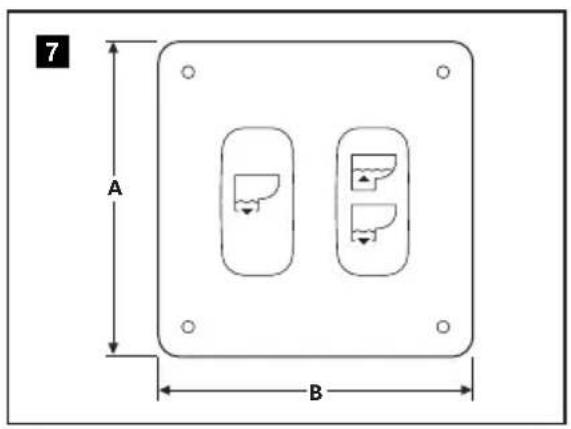
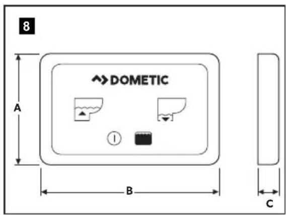
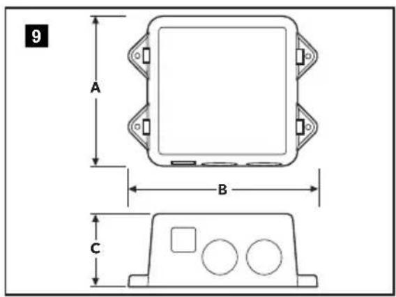
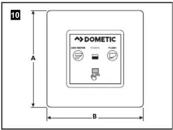
| Reference | Flush Toggle Switch (DFST) (Figure 7) | Touchpad (DFT) (Figure 8) | Control Module (Figure 9) | Touch Panel (DFSHW) (Figure 10) |
| A | 3.25" (83 mm) | 2" (51 mm) | 4.25" (108 mm) | 3" (76 mm) |
| B | 3.25" (83 mm) | 3.25" (83 mm) | 5.375" (137 mm) | 3.44" (87 mm) |
| C | 0.25" (6 mm) | 0.4" (11 mm) | 2.125" (54 mm) | 0.4" (11 mm) |
5 PREPARE FOR INSTALLATION
⚠ WARNING Failure to obey the following warnings could result in property damage, serious injury, or death:
- FLOOD HAZARD. For toilets that use raw-water systems: Do not install a raw-water pump controlled by an automatic demand switch.
- SHOCK OR FIRE HAZARD. Use the recommended fuse, circuit breaker, and wire size. Failure to comply could result in a fire.
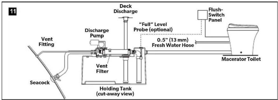
5.1 Laying out the fresh-water system
8100 Series
8500, 8600, 8700, and 8900 Series
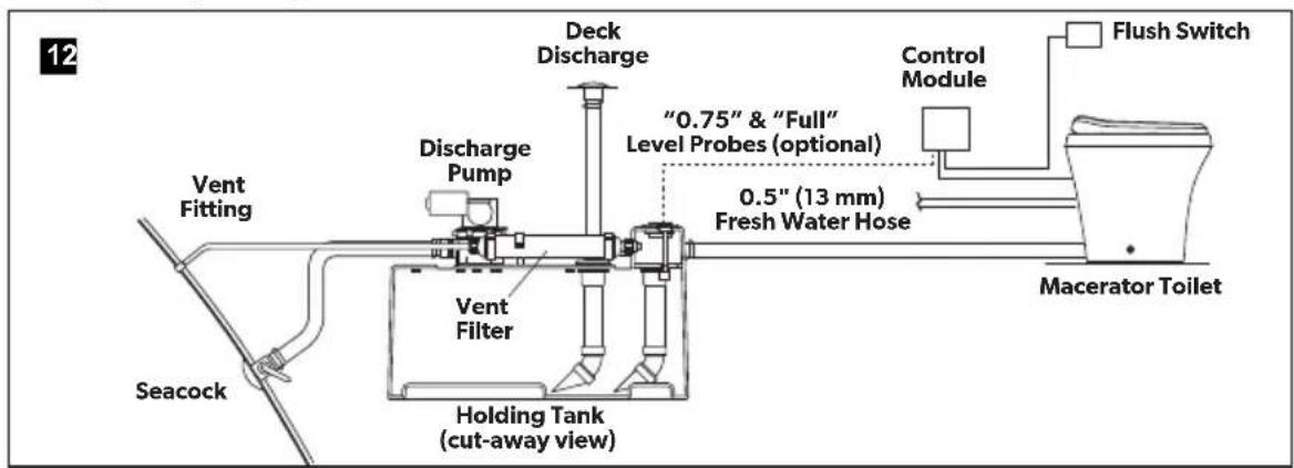
Use cold water only. Install a shut-off valve in the water line for maintenance purposes.
5.2 Laying out the raw-water system
- A separate pump is required for raw-water systems.
- If the raw-water pump draws more than 18 amps of current, a 12 or 24 VDC electrical relay must be installed.
- The pump is activated by the electrical signal from the toilet's electronic control module that would operate the integral water valve in a fresh water system.
Read before proceeding:
- Use cold water only. Include a shut-off valve in the water line for maintenance purposes.
- Use primary and secondary water filters.
- Install the vented loop as shown in figures 13 and 14. It must be equipped with an integral check valve that allows air into the line to prevent siphoning.
- The raw water pump must not be demand-type. The pump is controlled by a control module.
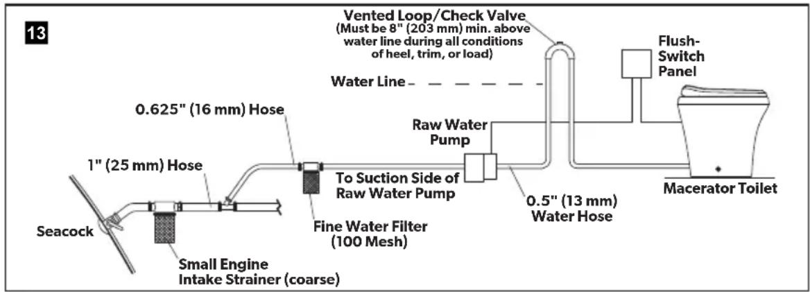
flowchart
graph LR
    A["Seacock"] --> B["1" (25 mm) Hose"]
    B --> C["0.625" (16 mm) Hose"]
    C --> D["Small Engine Intake Strainer (coarse)"]
    D --> E["To Suction Side of Raw Water Pump"]
    E --> F["Fine Water Filter (100 Mesh)"]
    F --> G["Raw Water Pump"]
    G --> H["0.5" (13 mm) Water Hose"]
    H --> I["Flush-Switch Panel"]
    I --> J["Macerator Toilet"]
    K["Vented Loop/Check Valve (Must be 8" (203 mm) min. above water line during all conditions of heel, trim, or load)"] --> L["Water Line"]
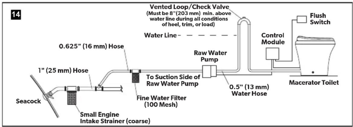
flowchart
graph LR
    A["Seacock"] --> B["1" (25 mm) Hose"]
    B --> C["0.625" (16 mm) Hose"]
    C --> D["Small Engine Intake Strainer (coarse)"]
    D --> E["Fine Water Filter (100 Mesh)"]
    E --> F["To Suction Side of Raw Water Pump"]
    F --> G["Raw Water Pump"]
    G --> H["0.5" (13 mm) Water Hose"]
    H --> I["Control Module"]
    I --> J["Flush Switch"]
    J --> K["Macerator Toilet"]
    L["Vented Loop/Check Valve (Must be 8"(203 mm) min. above water line during all conditions of heel, trim, or load)"] --> M["Water Line"]
5.3 Wiring/electronic control module connections
Read before proceeding:
- There must be a circuit breaker or fuse for every toilet.
- For marine applications, follow ABYC guidelines.
- For RV applications, refer to ANSI/RVIA LV and NFPA70/NEC standards (U.S.A.) or CEC I and II standards (Canada) for the recommended wire gauge. Refer to "1.3 Supplemental directives" on page 3.
- Use tinned, stranded copper wire.
- Use crimp-type wire connections. Do not use wire nuts, as wire nuts can corrode.
5.4 Planning the electrical connections
Plan the flush-switch panel and electronic control module locations, if applicable, so that the control module and wires are installed in locations that will always remain dry.
Several flush-switch assembly options are available from Dometic. Follow the instructions included with each flush switch assembly.
6 INSTALLATION
6.1 Installing the toilet with through-the-floor connections
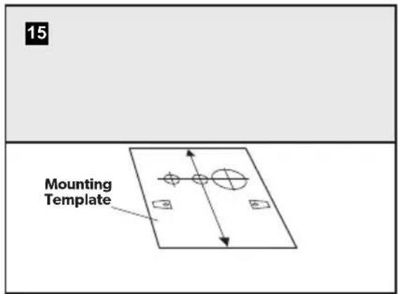
▶Place the floor-mounting template in the desired location. Keep at least 11" (279 mm) between the centerline of the template and any walls or interior fixtures.
▶Punch through the center of the holes and mounting-bracket corners in the template.
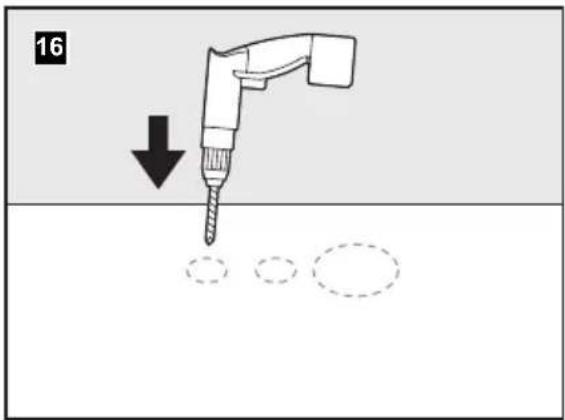
▶Remove the template from the floor.
▶Drill all access and fastener holes as indicated on the template, using the center punches as guides.
8100, 8500, 8600, 8900 models only: Do not drill mounting-bracket corners.
▶ Repeat the steps under figure 15 and 16 using the wall switch template.
▶For 8100 Series models, drill a 2.75" (70 mm) diameter hole.
For the 8500, 8600, 8700, and 8900 Series models, drill a 1" (25 mm) diameter hole.
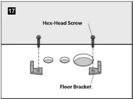
8100, 8500, 8600, 8900 models only
▶ Secure the floor brackets to the floor using the long hex-head screws from the toilet floor-bracket kit.
▶Loosely tighten with a 0.375" (10 mm) socket wrench, using the mounting bracket corner marks as guides.
Do not completely tighten the hex-head screws to the floor. Brackets will tighten when fastening the toilet to the brackets.
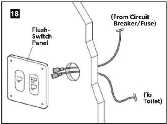
8100 models only
▶Turn the electrical power off.
▶Route wiring from the circuit breaker or fuse to the flush-switch panel location using 12-gauge (or larger) tinned copper wire.
▶Route wiring from the flush switch to the toilet location using 12-gauge (or larger) tinned copper wire. Route the wiring through the wiring access hole in the floor.
▶Fasten the wires to the appropriate leads on the back of the flush-switch panel using crimp-style wire connectors.
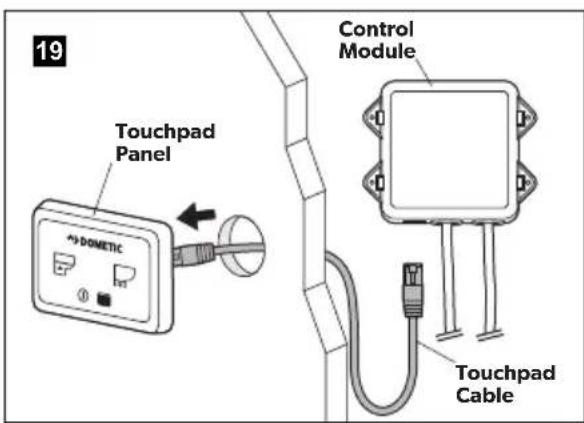
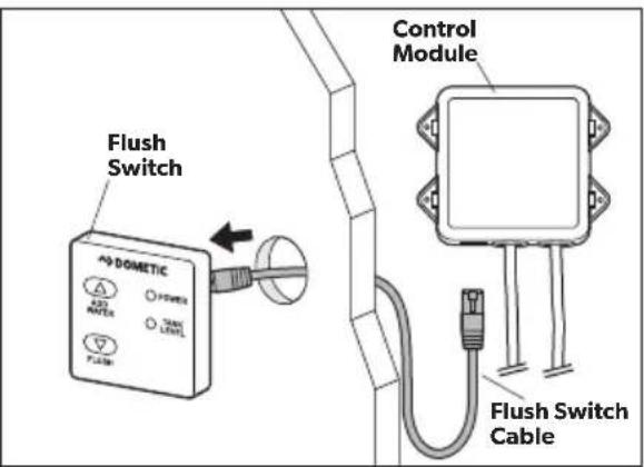
Route the touchpad or flush-switch Ethernet cable from the Ethernet connection on the control module through the access hole on the wall.
▶Secure the Ethernet cable to the touchpad or flush-switch panel.
Snap the touchpad or flush-switch panel cover onto the panel bracket.
8700 models with flush handle only
Route the 3-pin flush-handle cable from the control module to the toilet location.
Route the Ethernet cable to the status panel location and secure the cable to the connection.
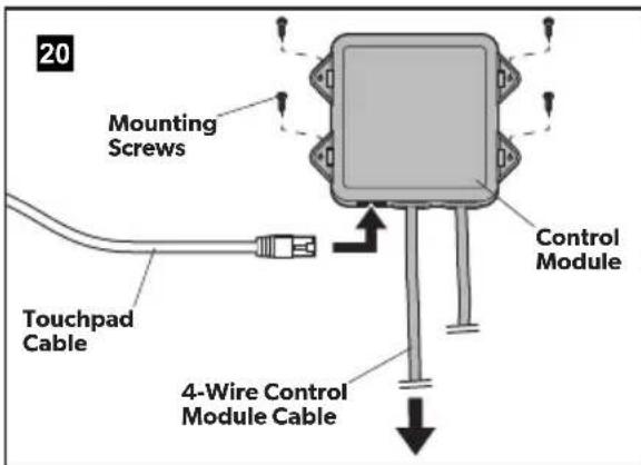
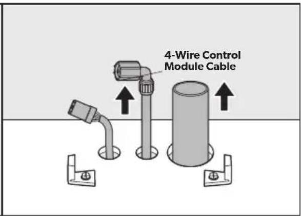
▶ Ensure that the electrical power is off and install the control module in a cool, dry location.
▶ Secure the flush-switch or touchpad Ethernet cable to the Ethernet connection on the control module.
▶Complete the wiring connections to the control module.
Before proceeding:
• Refer to the wiring diagram included with the parts list (packed separately).
- Refer to "5.3 Wiring/electronic control module connections" on page 9.
Route the 4-wire control module cable to the toilet through the access hole in the floor.
▶Proceed to "6.5 Finalizing the installation" on page 14.
6.2 Installing the toilet with through-the-wall connections
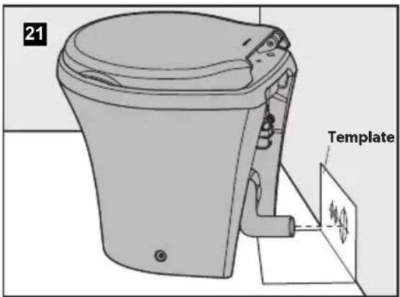
▶ Use the floor template to locate the vertical centerline of each hole.
▶Loosen the band clamp on the discharge loop outlet and remove the straight discharge hose fitting from the discharge adapter fitting.
▶ Attach the discharge elbow fitting to the discharge adapter fitting.
▶ Place the toilet in the desired position and mark the horizontal centerlines.
▶ Drill the hole sizes according to the template.
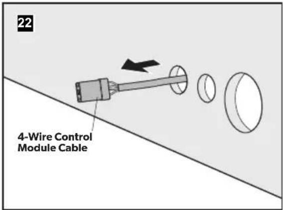
▶Route the wiring and plumbing through the drilled holes.
Refer to "5.3 Wiring/electronic control module connections" on page 9.
▶Provide extra discharge hose length for connection to the toilet. Refer to "4.2 Minimum system requirements" on page 5.
▶Proceed to "6.5 Finalizing the installation" on page 14.
6.3 Installing a toilet and bidet combination
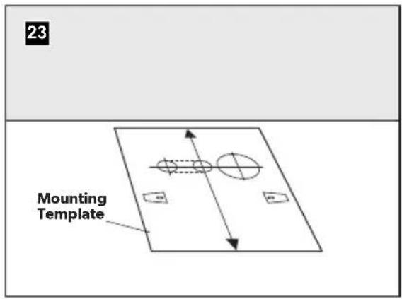
▶Place the floor-mounting template in the desired location. Keep at least 11" (279 mm) between the centerline of the template and any walls or interior fixtures.
▶Punch through the center of the holes and mounting bracket corners in the template.
▶Cut out the oblong access hole as marked on the floor template.
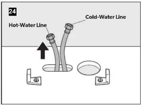
▶ Secure the floor brackets to the floor using the long hex-head screws from the toilet floor-bracket kit.
▶Tighten with a 0.375" (10 mm) socket wrench, using the corner marks as guides.
Do not completely tighten the hex-head screws to the floor. Brackets will tighten when fastening the toilet to the brackets.
▶Route the cold-water supply line to the toilet/bidet mixer-valve water line (blue band).
▶Route the hot-water supply line to the bidet faucet hot-water line (red band).
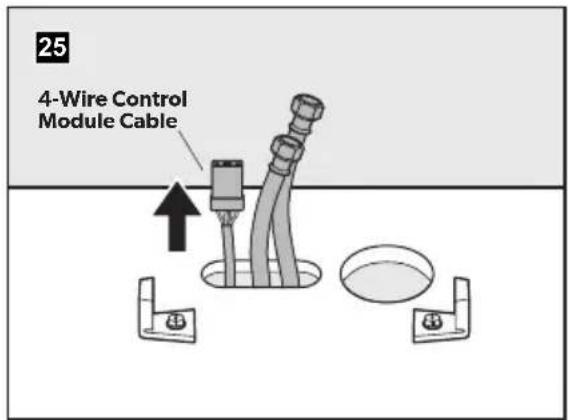
▶Route the wiring and discharge plumbing through the holes.
▶Provide extra discharge hose length to connect to the toilet. Refer to "4.2 Minimum system requirements" on page 5.
▶Proceed to "6.5 Finalizing the installation" on page 14.
6.4 Toilet system with "full tank" shut-down relay and tank monitor system
All installations can be set up to include "full tank" shut-down relay and tank monitor system options. Consult the wiring diagrams included with the product for further details. Wiring associated with these options needs to be done prior to the next step.
Route the input power wires from the "full tank" shut-down relay to the flush-switch panel.
▶Proceed to "6.5 Finalizing the installation" on page 14.
6.5 Finalizing the installation
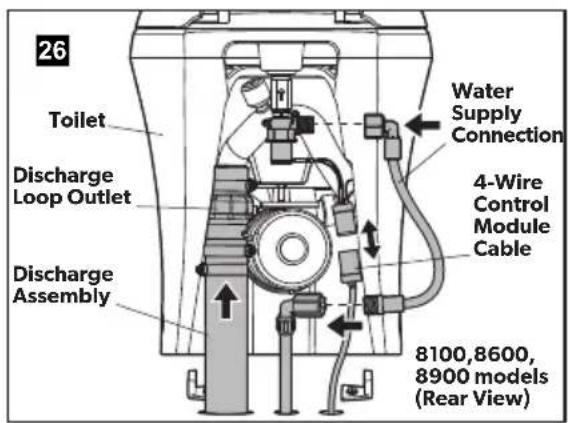
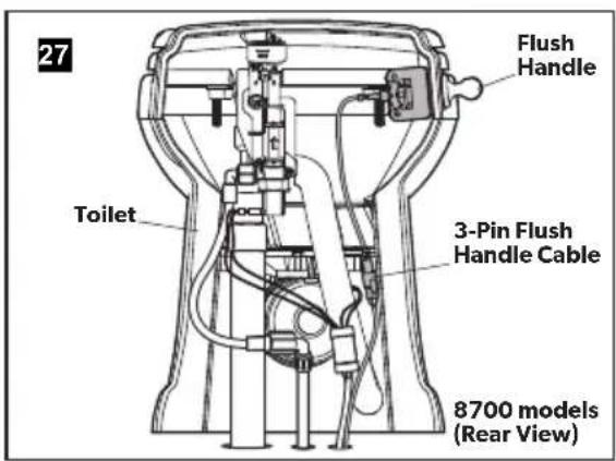
If installing an 8100 model toilet, perform the following steps prior to proceeding with the remainder of this section:
▶ Connect the water-valve adapter to the flexible water line with a hose clamp.
▶Connect the water-valve adapter to the water valve fitting.
8100, 8600, 8700, and 8900 models
Loosen the band clamp on the discharge loop outlet and remove the discharge adapter fitting/hose fitting assembly.
▶ Lubricate the discharge fitting with a few drops of liquid dish washing soap.
Insert the discharge fitting assembly into the discharge hose and connect them using two hose clamps.
▶Position the hose clamp screws 180° from each other.
▶Place the toilet near the access holes.
▶Connect the toilet water line to the water supply line.
▶ Make the final wiring connection:
8600 and 8900 models: Connect the 4-pin connector to the control module cable.
▶ 8100 models: Connect the flush-switch panel wires to the toilet wires.
8700 models: Connect the 3-pin flush handle connector to the 3-pin wire from the control module.
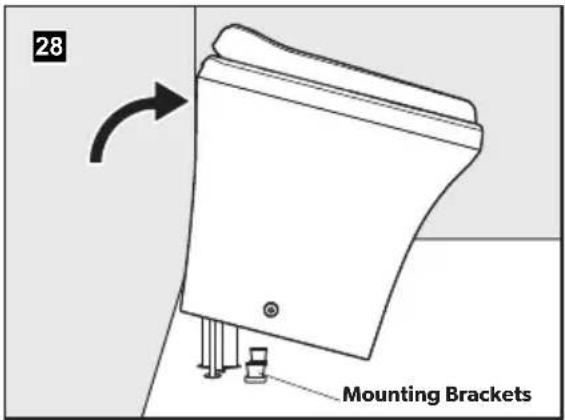
▶ Position the toilet over the floor brackets and tilt it up from the back.
▶Push the discharge-assembly fitting and hose into the discharge-loop outlet.
▶ Tighten the band clamp.
▶Lower toilet back down to the floor.
▶Turn on the water supply and electrical power to the toilet.
▶Check for leaks by pressing the flush switch. If there is a leak, tighten the connection.
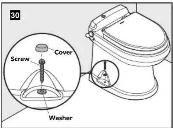
8700 models only
▶Drill pilot holes at the floor-mounting holes.
▶ Install the screws and washers (provided) using a 0.375" (10 mm) socket wrench.
▶ Place the plastic covers over the screws.
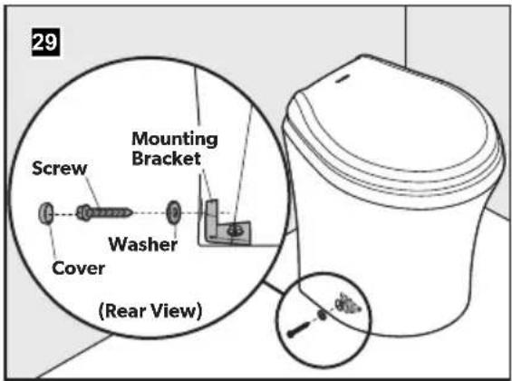
8100, 8500, 8600, 8900 models
▶Insert the plastic washers from the floor-bracket kit into the fastener holes.
▶Fasten the toilet to the brackets using the short screws included with the floor-bracket kit.
▶ Place the plastic covers over the floor-bracket screws.
7 DISPOSAL
Place the packaging material in the appropriate recycling waste bins, whenever possible. Consult a local recycling center or specialize dealer for details about how to dispose of the product in accordance with all applicable national and local regulations.
8 CUSTOMER SERVICE
For the Authorized Service Center near you, call between 8:00 a.m. and 5:00 p.m. (ET), Monday through Friday, or contact the nearest Parts Distributor.
Telephone: 1 800-321-9886 U.S.A. and Canada
330-439-5550 International
Fax: 330-496-3097 U.S.A. and Canada
330-439-5567 International
Website: www.dometic.com
DOMETIC
SANITAIRE
CUVETTES DE TOILETTES
natural_image
Line drawing of a cylindrical container with a lid, showing no text or symbols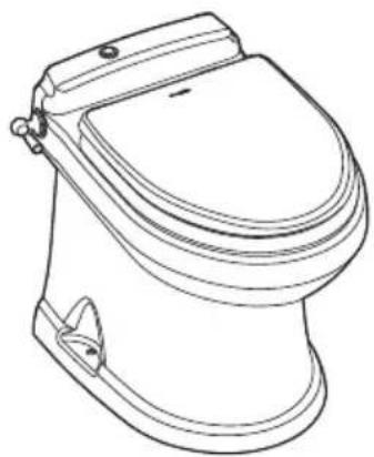
natural_image
Line drawing of a standard toilet with open lid and side door (no text or symbols)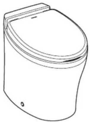
natural_image
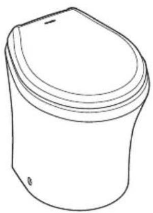
Line drawing of a standard open toilet (no text or symbols)8100/8500/8600/8700/8900
FR
Série 8000
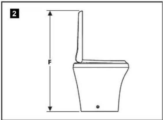
Dimensions, profil bas
| Référence | Série 8100(fig. 1 et 2) | Série 8600(fig. 1 et 2) | Série 8900(fig. 1 et 2) |
| A 15" (381 mm) 15" (381 mm) 14,75" (375 mm) | |||
| B 14,75" (375 mm) 14,75" (375 mm) 14,75" (375 mm) | |||
| C 18,375" (467 mm) 19,75" (502 mm) 18,25" (464 mm) | |||
| D 13,75" (349 mm) 14" (356 mm) 13,625" (346 mm) | |||
| E 14" (356 mm) 15,375" (391 mm) 14,875" (378 mm) | |||
| F 28" (711 mm) 30,5" (775 mm) 30,25" (768 mm) | |||

- Service Center & Dealer Locations
- Read these instructions carefully. These instructions MUST stay with this product.
- CONTENTS
- EXPLANATION OF SYMBOLS AND SAFETY INSTRUCTIONS
- Recognize safety information
- Understand signal words
- Supplemental directives
- U.S.A.
- Canada
- General safety messages
- GENERAL INFORMATION
- Included Parts
- Optional Parts\*
- INTENDED USE
- SPECIFICATIONS
- Materials
- Minimum system requirements
- Dimensions
- PREPARE FOR INSTALLATION
- Laying out the fresh-water system
- Laying out the raw-water system
- Read before proceeding:
- Wiring/electronic control module connections
- Planning the electrical connections
- INSTALLATION
- Installing the toilet with through-the-floor connections
- 8100, 8500, 8600, 8900 models only
- models only
- models with flush handle only
- Before proceeding:
- Installing the toilet with through-the-wall connections
- Installing a toilet and bidet combination
- Toilet system with "full tank" shut-down relay and tank monitor system
- Finalizing the installation
- 8100, 8600, 8700, and 8900 models
- models only
- 8100, 8500, 8600, 8900 models
- DISPOSAL
- CUSTOMER SERVICE
- SANITAIRE
- CUVETTES DE TOILETTES
Brand : DOMETIC
Model : MasterFlush MF 8989
Category : Toilet