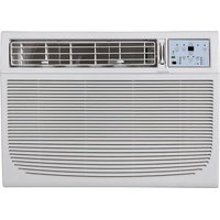
KSTAW18C - Air Conditioning Keystone - Free user manual and instructions
Find the device manual for free KSTAW18C Keystone in PDF.


| Product type | Reversible window air conditioner (heating and cooling) |
| Brand | Keystone |
| Model | KSTAW18C |
| Cooling capacity | 18 000 BTU/h |
| Heating capacity | Yes (heat pump) |
| Power supply | 115 V ~ 60 Hz |
| Refrigerant | R32 |
| Unit dimensions (Width x Height) | 26 1/2 in (673 mm) x 18 5/8 in (473 mm) |
| Approximate weight | 90 lb (40.8 kg) |
| Required window opening (min) | Height: 19 1/2 in (495 mm), Width: 31 in (787 mm) |
| Maximum window width | 42 in (1067 mm) |
| Operating modes | Auto, Cool, Heat, Fan, Dry, Sleep, Energy Saver |
| Fan speeds | Auto, Low, Med, High |
| Control | Electronic control panel and remote control |
| Air filter | Washable, monthly check recommended |
| Follow me function | "Follow Me" mode (remote thermostat) |
| Safety device | Current detection device on plug (TEST/RESET buttons) |
| Warranty | Manufacturer's warranty via Midea (customer service 1-866-646-4332) |
| Manual languages | FR, EN, ES |
Frequently Asked Questions - KSTAW18C Keystone
User questions about KSTAW18C Keystone
0 question about this device. Answer the ones you know or ask your own.
Ask a new question about this device
Download the instructions for your Air Conditioning in PDF format for free! Find your manual KSTAW18C - Keystone and take your electronic device back in hand. On this page are published all the documents necessary for the use of your device. KSTAW18C by Keystone.
USER MANUAL KSTAW18C Keystone
WINDOW TYPE ROOM AIR CONDITIONER
User Manual
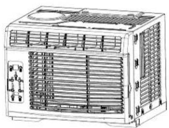
natural_image
Line drawing of an air conditioning unit with ventilation grilles and control panel (no text or labels)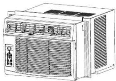
natural_image
Line drawing of an air conditioning unit with ventilation grilles and control panel (no text or symbols)
natural_image
Line drawing of a white industrial air conditioner unit with ventilation grilles and fan (no text or symbols)Model: KSTAW05DE KSTAW12CE
KSTAW06CE KSTAW14DE
KSTAW08CE KSTAW18C
KSTAW10DE KSTAW25C
IMPORTANT NOTE:
- Before using your air conditioner, please read this manual carefully and keep it for future reference.
Register your product today!
Congratulations on your new Keystone product! Please take a few minutes and follow the link or scan the QR code below to register your product so that we can activate warranties, send product updates, recommendations, help troubleshoot issues, offer maintenance advice, and communicate any product recalls or safety warnings in the event of one.
https://keystone-products.com/register-your-product

Warranty Information
Your product is protected by this warranty:

Your appliance is warranted by Midea. Any obligations for services and parts under this warranty must be performed by Midea Consumer Services or an authorized Midea servicer.
To contact a Customer Service Representative
Call Midea TOLL FREE
1-866-646-4332
Table of Contents
Important Safety Instructions ....03
Installation Instructions....08
Normal Sounds....20
Air Conditioner Features....21
Care and Cleaning....26
Troubleshooting Tips....27
Important Safety Instructions
READ THIS MANUAL
Inside you will find many helpful hints on how to use and maintain your air conditioner properly. Just a little preventive care on your part can save you a great deal of time and money over the life of your air conditioner. You'll find many answers to common problems in the chart of troubleshooting tips. If you review our chart of Troubleshooting Tips first, you may not need to call for service at all.
To prevent injury to the user or other people and property damage, the following instructions must be followed. Incorrect operation due to ignoring of instructions may cause harm or damage. The seriousness is classified by the following indications.

WARNING
The signal word indicates a hazard with a medium level of risk which, if not avoided, may result in death or serious injury.

CAUTION
The signal word indicates a hazard with a low degree of risk which, if not avoided, may result in minor or moderate injury.

NEVER DO THIS
This signal indicates the prompt operation is prohibited, if not avoided, may result in Product damaged or injury.

ALWAYS DO THIS
This signal means that the operation can be performed.

WARNING
- Plug in power plug properly. Otherwise, it may cause electric shock or fire due to excess heat generation. Do not operate or stop the unit by inserting or pulling out the power plug. It may cause electric shock or fire due to heat generation. Do not damage or use an unspecified power cord. It may cause electric shock or fire. If the power cord is damaged, it must be replaced by the manufacturer or an authorised service centre or a similarly qualified person in order to avoid a hazard.
• Always install circuit breaker and a dedicated power circuit. Incorrect installation may cause fire and electric shock. Do not operate with wet hands or in damp environment. It may cause electric shock. Do not direct airflow at room occupants only. This could damage your health. -
Always ensure effective grounding. Incorrect grounding may cause electric shock. Do not allow water to run into electric parts. It may cause failure of machine of electric shock. Do not modify power cord length or share the outlet with other appliances. It may cause electric shock or fire due to heat generation.
-
Unplug the unit if strange sounds, smell, or smoke comes from it. It may cause fire and electric shock. Do not use the socket if it is loose or damaged. It may cause fire and electric shock. Do not open the unit during operation. It may cause electric shock.
- Keep fire arms away. It may cause fire. Do not use the power cord close to heating appliances. It may cause fire and electric shock. Do not use the power cord near flammable gas or combustibles, such as gasoline, benzene, thinner, etc. It may cause an explosion or fire.
- Ventilate room before operating air conditioner if there is a gas leakage from another appliance. It may cause explosion, fire and, burns. Do not disassemble or modify unit. It may cause failure and electric shock.

CAUTION
- When the air filter is to be removed, do not touch the metal parts of the unit. It may cause an injury. Do not put a pet or house plant where it will be exposed to direct air flow. This could injure the pet or plant. Ventilate the room well when used together with a stove, etc. An oxygen shortage may occur.
- Do not use strong detergent such as wax or thinner but use a soft cloth. Appearance may be deteriorated due to change of product color or scratching of its surface. Do not clean the air conditioner with water. Water may enter the unit and degrade the insulation. It may cause an electric shock. Do not use for special purposes. Do not use this air conditioner to preserve precision devices, food, pets, plants, and art objects. It may cause deterioration of quality, etc.
- Stop operation and close the window in storm or hurricane. Operation with windows opened may cause wetting of indoor and soaking of house hold furniture. When the unit is to be cleaned, switch off, and turn off the circuit breaker. Do not clean unit when power is on as it may cause fire and electric shock or injury. Ensure that the installation bracket of the outdoor appliance is not damaged due toprolonged exposure.
- If bracket is damaged, there is concern of damage due to falling of unit. Always insert the filters securely. Clean filter once every two weeks. Operation without filters may cause failure. Hold the plug by the head of the power plug when taking it out. It may cause electric shock and damage. Turn off the main power switch when not using the unit for a long time. It may cause failure of product or fire.
- Do not place obstacles around air-inlets or inside of air-outlet. It may cause failure of appliance or accident. Do not place heavy object on the power cord and ensure that the cord is not compressed. There is danger of fire or electric shock. Do not drink water drained from air conditioner. It contains contaminants and could make you sick.
- Use caution when unpacking and installing. Sharp edges could cause injury.
- If water enters the unit, turn the unit off at the powei outlet and switch off the circuit breaker. Isolate supply by taking the power-plug out and contact a qualified service technician.

CAUTION
- This appliance is not intended for use by persons (including children) with reduced physical, sensory or mental capabilities or lack of experience and knowledge, unless they have been given supervision or instruction concerning use of the appliance by a person responsible for their safety.
• Children should be supervised to ensure that they do not play with the appliance. - If the supply cord is damaged, it must be replaced by the manufacturer, its service agent or similarly qualified persons in order to avoid a hazard.
• The appliance shall be installed in accordance with national wiring regulations.
• Do not operate your air conditioner in a wet room such as a bathroom or laundry room. - The appliance with electric heater shall have at least 1 meter space to the combustible materials.
- Contact the authorised service technician for repair or maintenance of this unit.
- Contact the authorised installer for installation of this unit.
- Do not operate the louvers with your hands, it may cause an injury.

NOTE:
The power supply cord with this air conditioner contains a current detection device designed to reduce the risk of fire. Please refer to the section Operation of Current Device for details. In the event that the power supply cord is damaged, it cannot be repaired-it must be replaced with acord from the Product Manufacturer.

WARNING
Avoid fire hazard or electric shock. Do not use an extension cord or an adaptor plug. Do not remove any prong from the power cord.
Grounding type wall receptacle
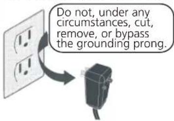
Power supply cord with 3-prong grounding plug and current detection device.

WARNING
For Your Safety
Do not store or use gasoline or other flammable vapors and liquids in the vicinity of this or any other appliance.
Prevent Accidents
To reduce the risk of fire, electrical shock, or injury to persons when using your air conditioner, follow basic precautions, including the following:
- Be sure the electrical service is adequate for the model you have chosen. This information can be found on the serial plate, which is located on the side of the cabinet and behind the grille.
- If the air conditioner is to be installed in a window, you will probably want to clean both sides of the glass first. If the window is a triple-track type with a screen panel included, remove the screen completely before installation.
- Be sure the air conditioner has been securely and correctly installed according to the installation instructions in this manual. Save this manual for possible future use in removing or installing this unit. When handling the air conditioner, be careful to avoid cuts from sharp metal fins on front and rear coils.
Electrical Information
The complete electrical rating of your new room air conditioner is stated on the serial plate. Refer to the rating when checking the electrical requirements.
- Be sure the air conditioner is properly grounded. To minimize shock and fire hazards, proper grounding is important. The power cord is equipped with a three-prong grounding plug for protection against shock hazards.
- Your air conditioner must be used in a properly grounded wall receptacle. If the wall receptacle you intend to use is not adequately grounded or protected by a time delay fuse or circuit breaker, have a qualified electrician install the proper receptacle. Ensure the receptacle is accessible after the unit installation.
- Do not run air conditioner without side protective cover in place. This could result in mechanical damage within the air conditioner.
- Do not use an extension cord or an adapter plug.
Operation of Current Device
(Applicable to the unit adopts current detection device only)
The power supply cord contains a current device that senses damage to the power cord. To test your power supply cord do the following:
- Plug in the Air Conditioner.
- The power supply cord will have TWO buttons on the plug head. Press the TEST button, you will notice a click as the RESET button pops out.
- Press the RESET button, again you will notice a click as the button engages.
- The power supply cord is now supplying electricity to the unit. (On some products this it also indicated by a light on the plug head.)

NOTE:
- Do not use this device to turn the unit on or off.
• Always make sure the RESET button is pushed in for correct operation. - The power supply must be replaced if it fails reset when either the TEST button is pushed, or it cannot be reset. A new one can be obtained from the product manufacturer.
- If power supply cord is damaged, it cannot be repaired. It MUST be replaced by one obtained from the product manufacturer.
NOTE: This air conditioner is designed to be operated under condition as follows:
| Cooling operation | Outdoor temp: | 64-109°F/18-43°C (64-125°F/18-52°C for special tropical models) |
| Indoor temp: | 62-90°F/17-32°C | |
| Heating operation | Outdoor temp: | 23-76°F/-5-24°C |
| Indoor temp: | 32-80°F/0-27°C |
Note: Performance may be reduced outside of these operating temperatures.

WARNING:
BEFORE PERFORMING ANY ELECTRICAL OR WIRING WORK, TURN OFF THE MAIN POWER TO THE SYSTEM.
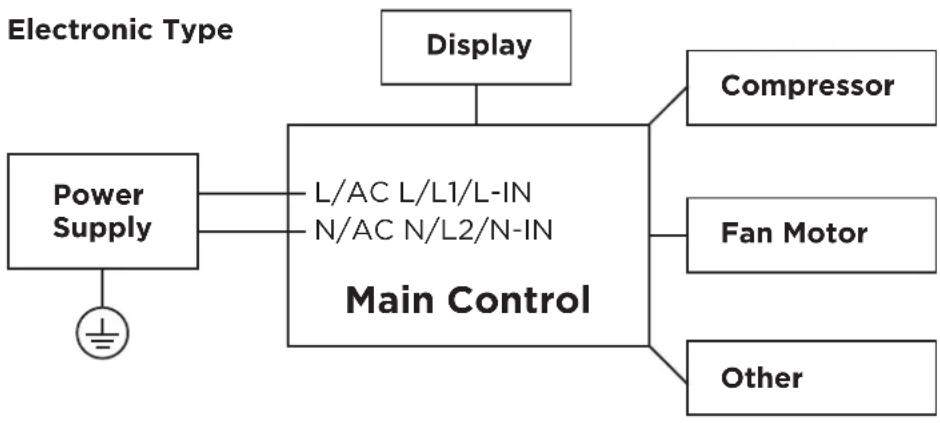
flowchart
graph TD
    A["Power Supply"] --> B["L/AC L/L1/L-IN N/AC N/L2/N-IN Main Control"]
    C["Display"] --> B
    D["Compressor"] --> B
    E["Fan Motor"] --> B
    F["Other"] --> B
NOTE:
Please strictly follow the wiring label attached to the machine for all wiring connections. The wiring diagram may vary for different unit. Please refer to the wiring diagram on the machine you have purchased. The above wiring diagram is a simplified version for preliminary illustration purposes only.

WARNING for Using R32 Refrigerant
- Do not use means to accelerate the defrosting process or to clean, other than those recommended by the manufacturer.
- The appliance shall be stored in a room without continuously operating ignition sources (for example: open flames, an operating gas appliance or an operating electric heater).
- Do not pierce or burn.
- Be aware that the refrigerants may not contain an odour.
- Appliance should be installed, operated and stored in a room with a floor area according to the amount of refrigerant to be charged. For specific information on the type of gas and the amount, please refer to the relevant label on the unit itself. When there are differences between the label and the manual on the minimum room area description, the description on label shall prevail.
- Appliance shall be installed, operated and stored in a room with a floor area larger than 4 m^2 . Appliance shall not be installed in an unvertilated space, if that space is smaller than 4 m^2 .
- No any open fire or device like switch which may generate spark/arcing shall be around appliance to avoid causing ignition of the flammable refrigerant used. Please follow the instructions carefully when storing or maintaining the appliance to prevent mechanical damage from occurring.
Installation Instructions
NOTE: The unit you purchased may be look like one of the followings:
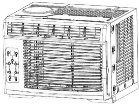
natural_image
Line drawing of an air conditioning unit with ventilation grilles and fan array (no text or labels)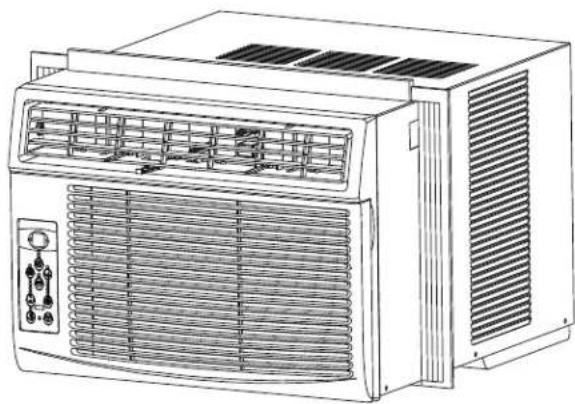
natural_image
Line drawing of a portable air conditioner unit with ventilation grilles and control panel (no text or symbols)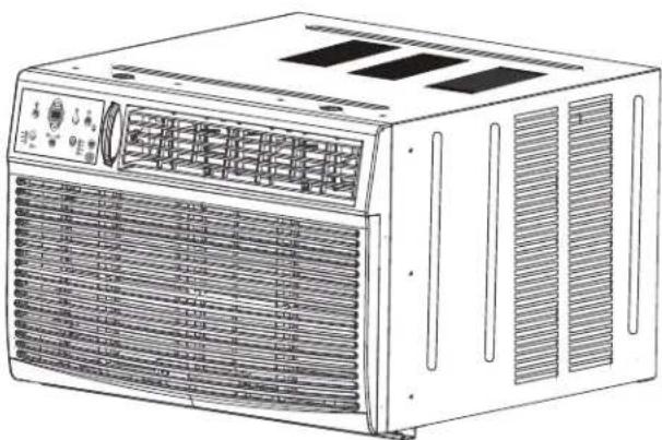
natural_image
Line drawing of an air conditioner unit with ventilation grilles and ventilation grilles (no text or symbols)
NOTE:
All the illustrations in this manual are for explanation purpose only. The air conditioner you have may be slightly different. The actual shape shall prevail.
Installation Instructions (for 5000 to 14000Btu/h)

BEFORE YOU BEGIN
Read these instructions completely and carefully.
IMPORTANT-Save these instructions for local inspector's use.
IMPORTANT-Observe all governing codes and ordianaces.
Note to installer- Be sure to leave these instructions with the consumer.
Note to consumer- Keep these instructions for future reference.
Skill level- Installation of this appliance requires basic mechanical skills.
Completion time- Approximately 1 hour. We recommend that two people install this product.
Proper installation is the responsibility of the installer.
Product failure due to improper installation is not covered under the Warranty.
You MUST use all supplied parts and use proper installation procedures as described in these instructions when installing this air conditioner.

WINDOW REQUIREMENTS
Your air conditioner is designed to install in standard double hung windows with opening widths of 23 to 36 inches (584mm to 914mm).
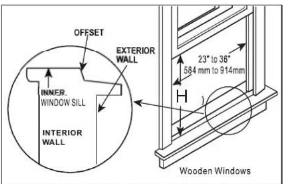
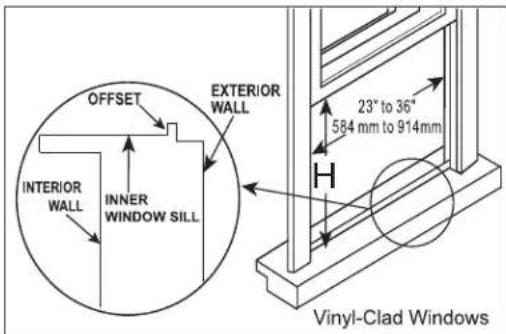
| Model H | 5000~6000Btu/h | 6000~8000Btu/h | 10000~14500Btu/h |
| 13"(330mm) | 14"(356mm) | 15-1/2 (394mm) |
Table 1

CAUTION
Do not, under any circumstances, cut or remove the third (ground) prong from the power cord.
Do not change the plug on the power cord of the air conditioner.
Aluminum house wiring may present special problems- consult a qualified electrician. When handling unit, be careful to avoid cuts from sharp metal edges and aluminum fins on front and rear coils.
TOOLS YOU WILL NEED
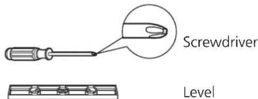
TOOLS YOU MAY USE


NOTE:
Save Carton and these Installation Instructions for future reference. The carton is the best way to store unit during winter, or when not in use.
1 PREPARE THE WINDOW
Lower sash must open sufficiently to allow a clear vertical opening. The window opening height shall be based on the different Models:
13inches/330mm (5k\~6k units), 14inches/356mm (6k\~8k units), 15-1/2inches/394mm (10k\~12k units). Side louvers and the rear of the AC must have clear air space to allow enough airflow through the condenser, for heat removal. The rear of the unit must be outdoors, not inside a building or garage.
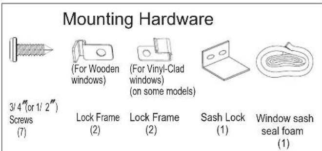
2 PREPARE AIR CONDITIONER
A: Remove the air conditioner from the carton and place on a flat surface.
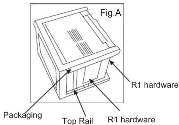
B: Remove top rail and R1 hardware and weather stripping from the packaging material as shown in Fig. A(R1 hardware and weather stripping are only available for≥15000Btu / h models).
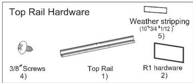
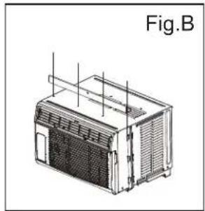
C: Align the hole in the top rail with those in the top of the unit as shown in Fig.B
natural_image
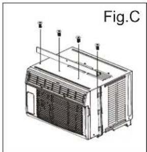
Technical line drawing of a modular device labeled Fig.B, showing internal components and ventilation ducts (no text or symbols on the device itself)D: Secure the top rail to the unit with the 3/8" Screws as shown in Fig.C.
natural_image
Technical line drawing of a portable air conditioner unit (no text or symbols)NOTE: For safety reasons, all four (4) screws MUST be securely fastened.
NOTE: The top rail hardware and the Fig.A, Fig.B and Fig.C are not applicable to the units more than 10000Btu/h. Before installing unit, the top rail must be assembled on the unit (For <10000Btu/h models only).
3 INSTALL THE ACCORDION PANELS
NOTE: Top rail and Sliding Panels at each side are offset to provide the proper pitch to the rear of (5/16"). This is necessary for proper condensed water utilization and drainage. If you are not using the Side Panels for any reason, this pitch to the rear must be maintained.

natural_image
Simple line drawing of a vertical corrugated structure with an arrow indicating left motion (no text or symbols)A. Place unit on floor, a bench or a table. Hold the Accordion Panel in one hand and gently pull back the center to free the open end. See Fig.1
Fig.1
B. Slide the free end "I" section of the panel directly into the cabinet as shown in Fig. 2. Slide the panel down. Be sure to leave enough space to slip the top and bottom of the frame into the rails on the cabinet.
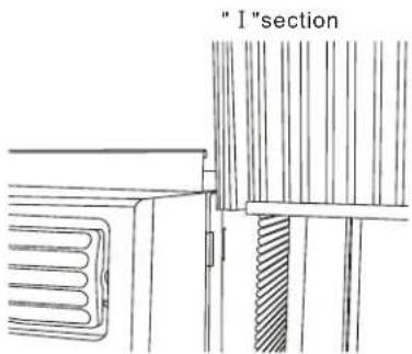
Fig.2
C. Once the panel has been installed on the side of the cabinet, make sure it sits securely inside the frame channel by making slight adjustments. Slide the top and bottom ends of the frame into the top and bottom rails of the cabinet. Fig .3.
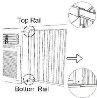
Fig.3
D. Slide the panel all the way in and repeat on the other side.
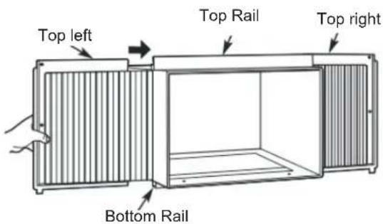
Fig.4
NOTE: If storm window blocks AC, see Fig. 11.
4 SECURE THE ACCORDION PANELS
A. Keep a firm grip on the air conditioner, carefully place the unit into the window opening so the bottom of the air conditioner frame is against the window sill (Fig.5A and Fig.5B). Carefully close the window behind the top rail of the unit.
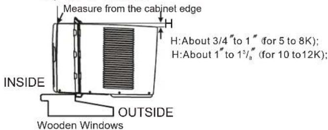
Fig.5A
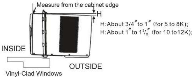
Fig.5B
NOTE: Check that air conditioner is tilted back about H (Fig.5A and Fig.5B) (tilted about 3° to 4° downward to the outside). After proper installation, condensate should not drain from the overflow drain hole during normal use, correct the slope otherwise.
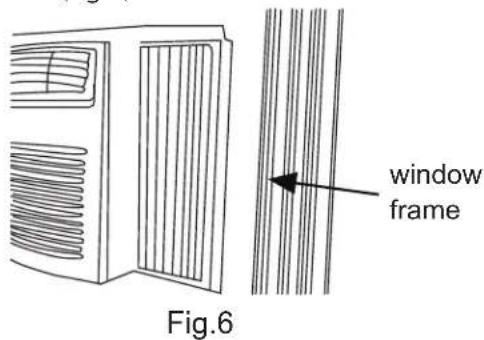
B. Extend the side panels out against the window frame(Fig.6).
5 INSTALL SUPPORT BRACKET
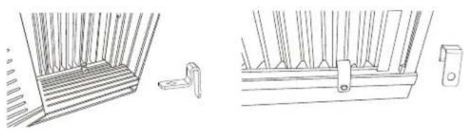
A. Place the frame lock between the frame extensions and the window sill as shown(Fig.7A for Wooden windows), (Fig.7B for Vinyl-Clad windows).
natural_image
Technical line drawing of a window frame structure with no visible text or symbolsFig.7A Fig.7B
A: For wooden windows:
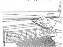
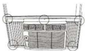
Drive 1/2" (12.7 mm) locking screws through the frame lock and into the sill (Fig.8A).
NOTE: To prevent window sill from splitting, drill 1/8 " (3mm) pilot holes before driving screws.
Drive 1/2" (12.7mm) locking screws through frame holes into window sash (Fig.8B).
B: For Vinyl-Clad windows:
Drive 1/2" (12.7 mm) locking screws through the frame lock and into the window sashl (Fig.8B).
NOTE: Before driving the screws, use a drill to drill 5 holes through the holes in the frame lock and frame extensions into the windows sash as shown (Fig. 8B).
natural_image
Architectural line drawing of a building facade with vertical supports and horizontal beams (no text or symbols)Fig.8A Fig.8B
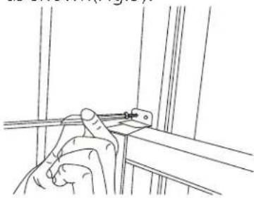
C. To secure lower sash in place, attach right angle sash lock with 3/4" (19mm) or 1/2" (12.7mm) screw as shown(Fig.9).
natural_image
Line drawing of a hand holding a tool near a metal bracket (no text or symbols)Fig.9
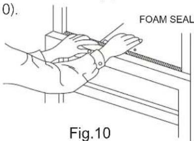
D. Cut window sash seal foam and insert it in the space between the upper and lower sashes
(Fig. 10).
7 INSTALL R1 HARDWARE (only applicable to ≥15000Btu/h)
In order to minimize air leaks and ensure optimal insulation, it is necessary to install the included R1 hardware to the side curtain. Follow the instructions below.
Step 1. After the unit is installed to the window, measure the inner width of the side curtain as shown (Fig. 11).
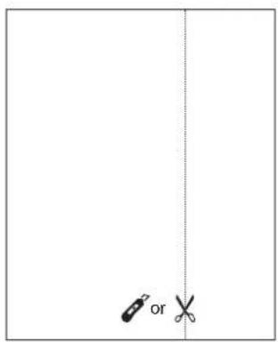
Step 2. Remark a line on the provide R1 insulation panel according to a length 1/8" (3mm) less than the measured width in step 1, then cut the R1 insulation panel along the line (Fig .12).
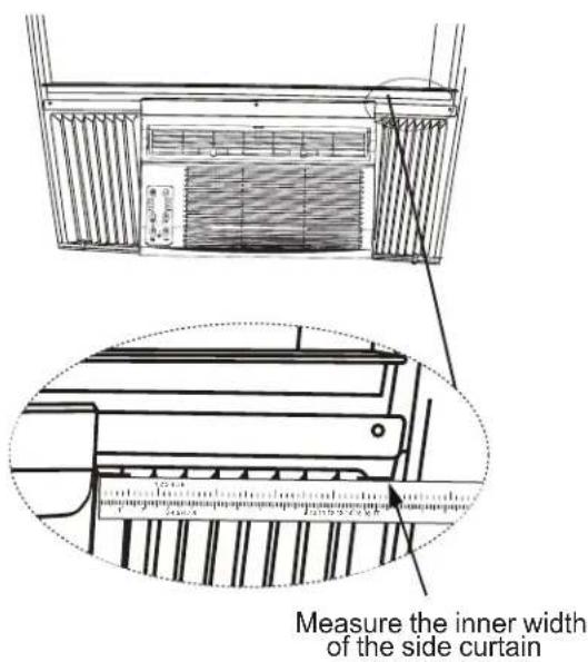
Fig.11
natural_image
Simple diagram showing two scissors placed vertically against a dashed vertical line (no text or symbols)Fig.12
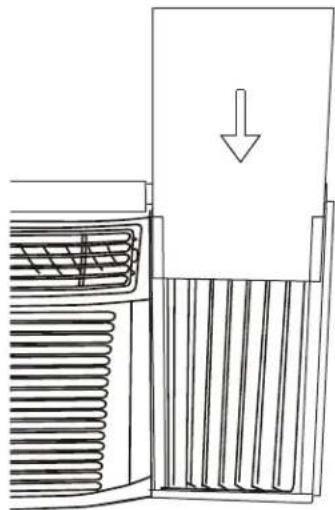
Step 3. Slide the R1 insulation panel into the side curtain, the side with pattern should facing the indoor side.(Fig.13)
natural_image
Diagram of a heat exchanger with cooling fins and a downward arrow indicating airflow (no text or symbols)Fig.13
Step 4. Repeat on the other side.
8 INSTALL WEATHER STRIPPING
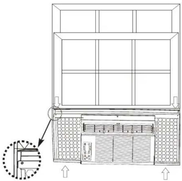
In order to minimize air leaks between the room air conditioner and the window opening, trim the weather stripping with a proper length, peel off the protective backing and plug any gaps if needed (Fig .14).
natural_image
Technical line drawing of a cabinet or enclosure with internal components and ventilation grilles, showing no text or symbols.Fig.14
If AC is Blocked by Storm Window
Add wood as shown in Fig.15, or remove storm window before air conditioner is installed.
If Storm Window Frame must remain, be sure the drain holes or slots are not caulked or painted shut. Accumulated Rain Water or Condensation must be allowed to drain out.
Removing AC From Window
Turn AC off, and disconnect power cord.
Remove sash seal from between windows, and unscrew safety sash lock.
Remove screws installed through frame and frame-lock.
Remove the R1 Panel and close (slide) side panels into frame.
Keeping a firm grip on air conditioner, raise sash and carefully remove.
Be carefully not to spill any remaining water while lifting unit from window. Store parts WITH air conditioner.
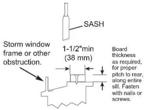
Fig.15
Installation Instructions (for 18000 and 25000Btu/h)

BEFORE YOU BEGIN
Read these instructions completely and carefully.
IMPORTANT-Save these instructions for local inspector's use.
IMPORTANT-Observe all governing codes and ordianaces.
Note to Installer- Be sure to leave these instructions with the Consumer.
Note to Consumer- Keep these instructions for futrue reference
Skill level- Installation of this appliance requires basic mechanical skills.
Completion time- Approximately 1 hour. We recommend that two people install this product.
Proper installation is the responsibility of the installer.
Product failure due to improper installation is not covered under the Warranty.
You MUST use all supplied parts and use proper installation procedures as described in these instructions when installing this air conditioner.

CAUTION
Do not, under any circumstances, cut or remove the third (ground) prong from the power cord. Do not change the plug on the power cord of the air conditioner. Aluminum house wiring may present special problems- consult a qualified electrician. When handling unit, be careful to avoid cuts from sharp metal edges and aluminum fins on front and rear coils.

NOTE:
Save Carton and these Installation Instructions for future reference. The carton is the best way to store unit during winter, or when not in use.
Preliminary Instructions
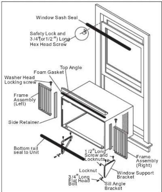
Do the following before starting to install unit. See illustrations below.
Check dimensions of your unit to determine model type:
| Unit Height: | 18 58 " | 17 58 " |
| Unit Width: | 26 12 " | 23 58 " |
| Min. Window Opening: | 19 12 " | 18 12 " |
| Min. Window Width: | 31" | 28" |
| Max. Window Width: | 42" | 40 " 12 " |
-
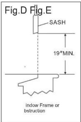
Check window opening size-- the mounting parts furnished with this air conditioner are made to install in a wooden sill double-hung window. The standard parts are for window dimensions listed above. Open sash to a minimum of 19 inches(483mm). See Fig.D.
-
Check condition of window-- all wood parts of window must be in good shape and able to firmly hold the needed screws. If not, make repairs before installing unit.
-
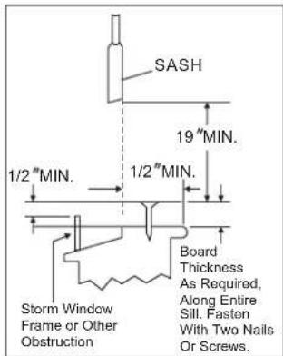
Check your storm windows-- if your storm window frame does not allow the clearance required, correct by adding a piece of wood as shown in Fig.E, or by removing storm window while room air conditioner is being installed.
-
Check for anything that could block airflow- check area outside of window for things such as shrubs, trees, or awnings. Inside, be sure furniture, drapes, or blinds will not stop proper airflow.
-
Check the available electrical service-Power supply must be the same as that shown on the unit serial nameplate. Power cord is 48 inches long. Be sure you have an outlet near.
-
Carefully unpack air conditioner- Remove all packing material. Protect floor or carpet from damage. Two people should be used to move and install unit.
Hardware(Packed with the unit)
 | 7/16 inch Locking screw and Flat washer for window panels | 2ea. |
 | 3 / 4 or 1/2)inch Long Hex-head Screw | 7 |
 | Safety Lock | 1 |
 | 1 / 2 inch Long screw and Locknut | 4ea. |
| [YSTY] | 3 / 4 inch Long Flat Head Bolt and Locknut | 2ea. |
 | Sill Angle Bracket | 2 |
 | Lock Frame(For Wooden windows)(on some models) | 2 |
 | 3 / 4 inch Long Screw(on some models) | 2 |
 | Long hex-head locking screw for top angle, side retainer 5 /16 inch Long | 10 |
 | Foam insert | 2 |
 | Window sash seal foam | 1 |
 | Safety Lock (for Vinyl-Clad window)(on some models) | 2 |
| Locking screw #10X 1/4 panhead Phillips screws (for Vinyl-Clad window)(on some models) | 2 | |
 | R1 hardware | 2 |
 | Weather stripping (10*3/4 *1/12) | 5 |
 | Sill angle bracket (on some models) | 2 |
| NOET:R1 hardware and Weather stripping is only for models with capacity larger than 15000 Btu/h. | ||
NOET:R1 hardware and Weather stripping is only for models with capacity larger than 15000 Btu/h.
Tools Required A large flat blade screwdriver; Tape measure; Adjustable wrench or pliers; Pencil; Level Socket wrenches; Phillips Screwdriver.
1 Remove Air Conditioner from Cabinet
NOTE: Remove any packaging material from cabinet exterior.
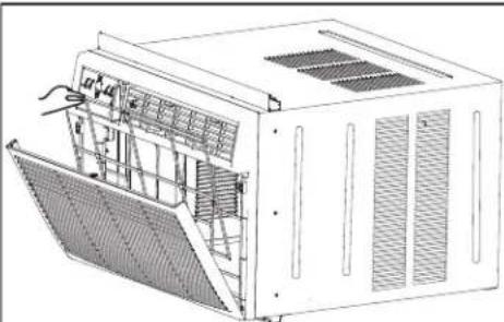
- Pull down front grille and remove filter. (See Fig.1).
- Lift front grille upwards and place to one side.
- Locate the four front screws and remove. These screws will be needed to re-install the front panel (see Fig.2).
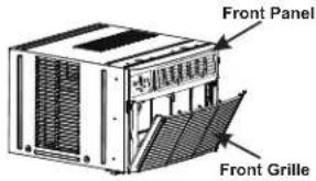
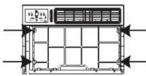
natural_image
Diagram of an air conditioner unit with control panel and ventilation ducts (no text or labels)Fig.1 Fig.2
- Push metal cabinet side to release plastic tabs on each side of front panel (see Fig.3).
- Gently lift front panel off unit(see Fig.3A).
- Disconnect the connector plug of the display panel from the unit and place front panel to one side(see Fig.4).
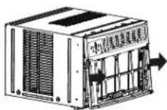
Fig.3
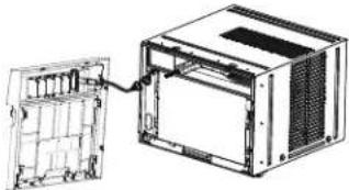
natural_image
Technical line drawing of a computer case with an open panel and internal casing (no text or symbols)Fig.4
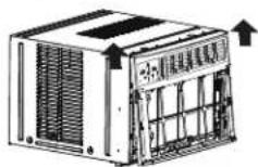
Fig.3A
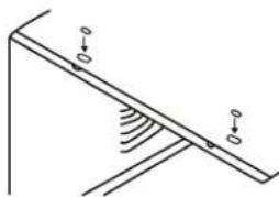
- Remove shipping screws from top of unit and also on the side by the base if installed(see Fig.5).
- Hold the cabinet while pulling on the base pan handle, and carefully remove the unit.
- Add two foam inserts to holes in top of cabinet where shipping screws were removed from (see Fig .6)

Fig.5
natural_image
Simple line drawing of a mechanical setup with two vertical supports and a curved surface (no text or symbols)Fig.6
- Your unit may come with internal packaging. This packaging must be removed prior to installing the air conditioner back into the cabinet.(see Fig .7).
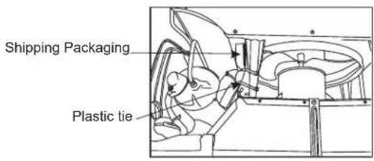
Fig.7
2 Install top angle and side Bracket
-
Attach foam gasket to top angle above holes as shown in Fig.6.
-
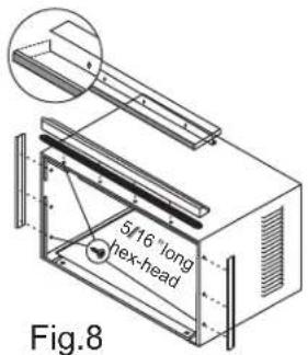
Install top angle and side retainers to cabinet as shown in Fig.8(10 screws).
3 Assemble Window Filler Panels
- Place cabinet on floor, a bench, or a table.
- Slide "I" section of window filler panel into side retainer on the side of the cabinet (see Fig.9 & Fig.10). Do both sides.
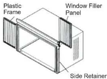
Fig.9
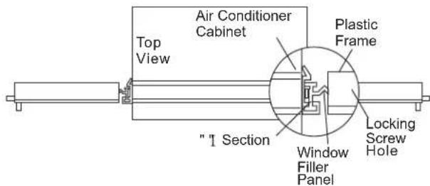
Fig.10
- Insert top and bottom legs of window filler panel frame into channel in the top angle and bottom rail. Do both sides.
- Insert washer head locking 7/16" screws (2) into holes in top leg of filler panel frame (see step 6). Do not totally tighten. Allow leg to slide freely. Screwswill be tightened after section 6.
4 Place Cabinet in window
- Open window and mark center of window inner sill as shown(Fig.11).
- Place cabinet in window with bottom sill angle firmly seated over window sill as shown. Bring window down temporarily behind top angle to hold cabinet in place(Fig.12).
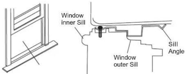
Fig.11 Fig.12
- Shift cabinet left or right as needed to line up center of cabinet on center line marked on inner sill.
- For wooden window: Fasten cabinet to window inner sill with two screws into holes (Fig.13) (You may wish to pre-drill pilot holes). For Vinyl-Clad window: Place two safety locks into the holes located in the bottom of the cabinet and drive two #10X1/4" pan-head Phillips locking screws through the safety locks into the cabinet as shown (Fig.13B).
- Remove protective strip from adhesive side of Bottom Rail Foam Seal. Apply Seal over screws fastening bottom rail to window inner sill.
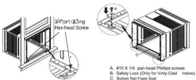
Fig.13 Fig.13B
5 Install Support Bracket
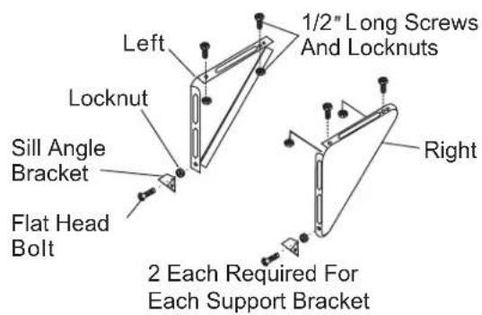
- Hold each support bracket flush against outside of sill, and tight to bottom of cabinet as shown in Fig.15A. Mark brackets at top level of sill and remove.
- Assemble sill angle bracket to support brackets at the marked position(Fig.15B).
Hand tighten, but allow for any changes later.
NOTE: Check that air conditioner is tilted back about 1^1/4 " to 1^5/6 " (tilted about 3^ to 4^ downward to the outside). After proper installation, condensate should not drain from the overflow drain hole during normal use, correct the slope otherwise (Fig. 14).
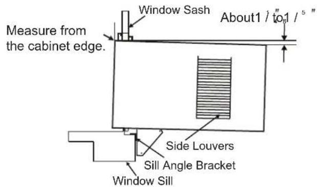
Fig.14
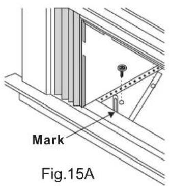
Fig.15B
- Install support brackets(with sill angle brackets attached) to correct hole in bottom of cabinet as shown in Fig.16.
- Tighten all 6 bolts securely.
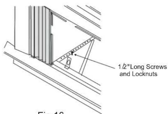
Fig.16
6 Extend Window Filler Panels
- Carefully raise window to expose filler panel locking screws. Loosen screws so filler panels slide easily.
- Extend panels to fill window opening completely. Tighten locking screws on top (Fig.17).
- Close window behind top angle.
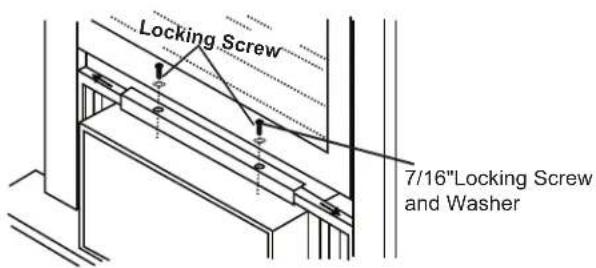
Fig.17
- Attach the top angle to window frame: Use a 3/32" drill bit to drill one hole through the hole in the middle of top angle into the window frame, and drive one 3/4" (or 1/2") HEX-HEAD locking screw through hole in the middle of top angle into the window frame as shown (Fig.17A)
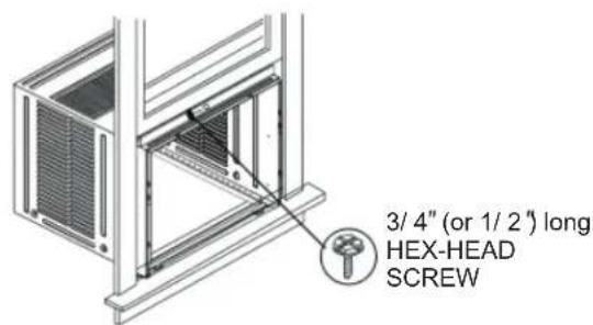
Fig.17A
7 Attach Window Filler Panels to Window Frame
- Extend the window filler panels out against the window frame.
- Use a 1/8" drill bit to drill a starter hole through the hole in the top leg of each window filler panel and into the window sash (Fig. 18A and Fig. 18B). Connect with one 3/4" (or 1/2") long hex head screw.

A.3/4"(or 1/2)"long hex head screw
B. Left-hand Window Filler Panel Top Leg
C. Window channel
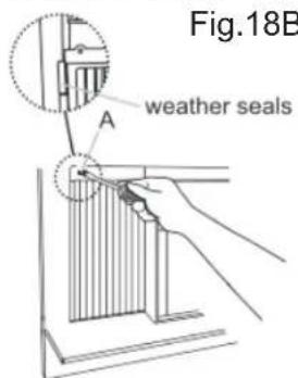
A.3/4"(or1/2") long hex head screw
- Attach the Lock Frames to the winow sill using two 3/4" (19mm) screws(Fig.18C) (on some models)
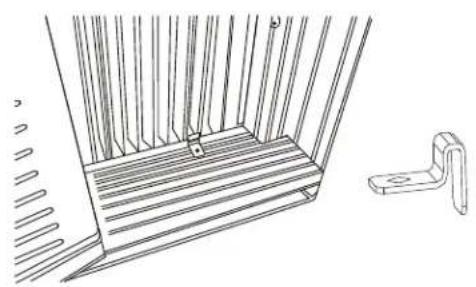
natural_image
Technical line drawing of a window frame with vertical bars and a separate handle (no text or symbols)Fig.18C
8 Install Window Sash Seal and Safety Lock
- Trim sash seal to fit window width. Insert into space between upper and lower sashes (Fig.18).

Fig.18
- Attach right angle safety lock (Fig. 19).
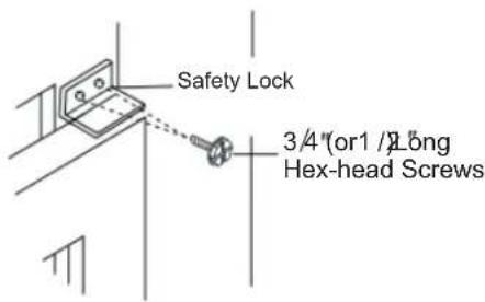
Fig.19
9 Install Chassis into Cabinet and Install Front to Unit
- Lift air conditioner and carefully slide into cabinet leaving 6 inches protruding.
- DO NOT push on controls or finned coils.
- Be sure chassis is firmly seated towards rear of cabinet.
- Installation of front is the reverse of removal outlined in Section 1.
10 Install R1 HARDWARE (only applicable to ≥15000Btu/h models)
In order to minimize air leaks and ensure optimal insulation, it is necessary to install the included R1 hardware to the side curtain. Follow the instructions below.
Step 1. After the unit is installed to the window, measure the inner width of the side curtain as shown (Fig.20).
Step 2. Remark a line on the provided R1 insulation panel according to a length 1/8" (3mm) less than the measured width in step 1, then cut the R1 insulation panel along the line (Fig. 12).
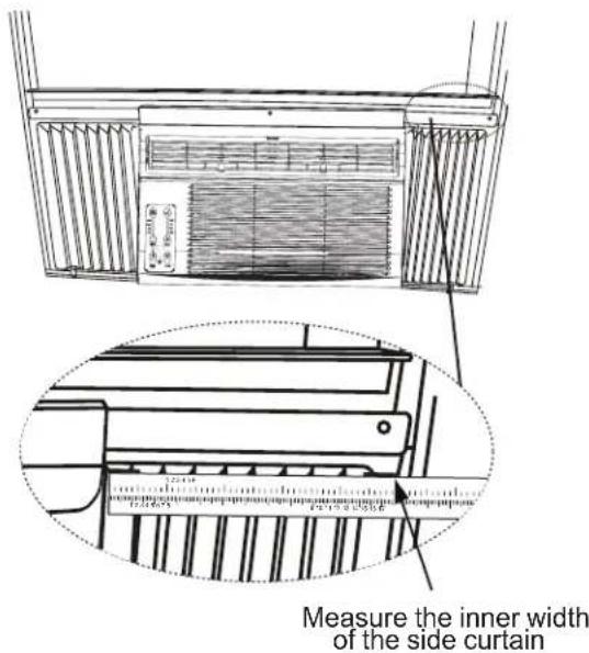
Fig.20
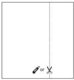
Fig.21
Step 3. Slide the R1 insulation panel into the side curtain, the side with pattern should facing the indoor (Fig. 22).

natural_image
Diagram of a mechanical device with internal components and a downward arrow indicating motion (no text or symbols)Fig.22
Step 4. Repeat on the other side.
11 Install WEATHER STRIPPING
In order to minimize air leaks between the room air conditioner and the window opening, trim the weather stripping with a proper length, peel off the protective backing and plug any gaps if needed (Fig.23).
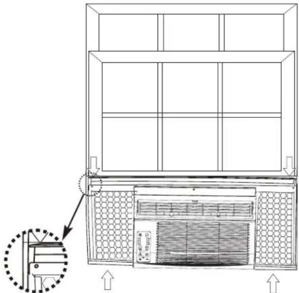
Fig.23
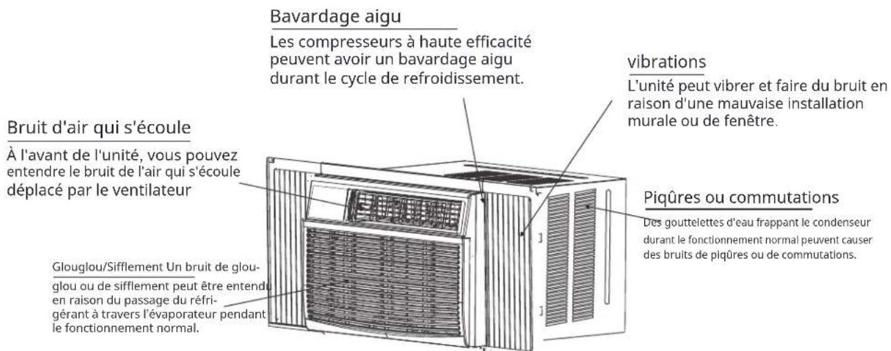
Normal Sounds
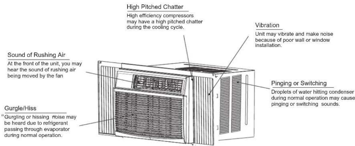

NOTE:
All the illustrations in this manual are for explanation purpose only. The air conditioner you have may be slightly different. The actual shape shall prevail.
Air Conditioner Features

WARNING
To reduce the risk of fire, electric shock, or injury to persons, read the IMPORTANT SAFETY INSTRUCTIONS before operating this appliance.

CAUTION
Please always wait 3 minutes when turning unit off then on again, and when changing from cool to fan and back to cool. This prevents compressor from overheating & possible circuit breaker tripping.
To begin operating the air conditioner, follow these steps:
- Set the thermostat to the highest number (coldest or cooler setting).
- Set the selector control to the highest COOL setting.
- Adjust the louver for comfortable air flow (see Air Directional Louvers).
- Once the room has cooled, adjust the thermostat to the setting you find most comfortable.
- Make sure that the air flow inside and outside are not obstructed by anything.
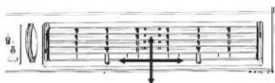
Air Directional Louvers
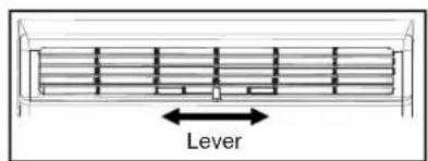
Air Direction for 05K
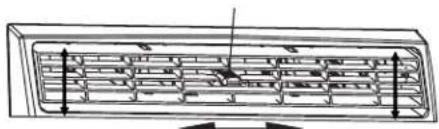
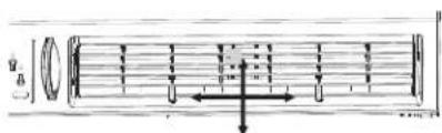
The louvers will allow you to direct the air flow Left or Right throughout the room as needed.
Move the Levers from side to side until the desired Left/Right direction is obtained.
Levers
natural_image
Pure schematic diagram of a mechanical or structural component with no text, numbers, or symbolsAir Direction
Levers
natural_image
Technical line drawing of a mechanical component with internal channels and dimension arrows (no text or symbols)Air Direction
Levers

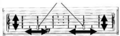
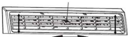
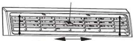
Air Direction(4-way)
for 06K, 08K, 10K, 12K, 14K, 18K, 25K
The louvers will allow you to direct the air flow Up or Down(on some models) and Left or Right throughout the room as needed. Pivot horizontal louvers until the desired Up/Down direction is obtained. Move the Lever (s) from side to side until the desired Left/Right direction is obtained.
Fresh Air Vent Control (for 10-14K MODELS)
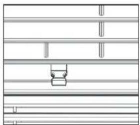
natural_image
Pure architectural floor plan lines without any text, numbers, or symbolsFig. A (VENT CLOSED)
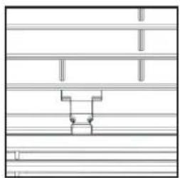
natural_image
Pure architectural floor plan lines without any text, numbers, or symbolsFig. B (VENT OPEN)
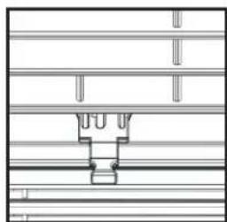
natural_image
Pure technical line drawing of a mechanical assembly without any text, numbers, or symbolsFig. C (VENT & EXHAUST OPEN)
The Fresh Air Vent allows the air conditioner to:
- Recirculate inside air - Vent Closed (See Fig.A)
- Draw fresh air into the room- Vent Open (see Fig.B)
- Exchange air from the room and draws fresh air into the room - Vent and Exhaust Open (see Fig.C)
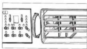
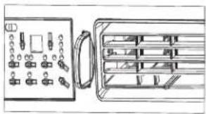
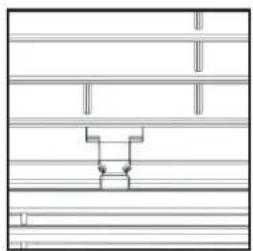
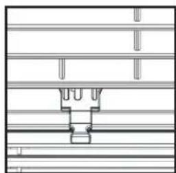
Fresh Air Vent Control (on 18K and 25K models):
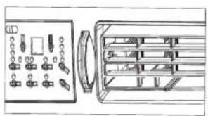
natural_image
Diagram of an electronic device rear panel with ports and connectors (no text or labels)Fig. A (VENT CLOSED)
natural_image
Diagram of a device rear panel with connectors and a close-up view of the front panel (no text or symbols visible)Fig. B (VENT OPEN)
natural_image
Diagram of a device panel with ports and a close-up view of internal components (no text or symbols)Fig. C (VENT & EXHAUST OPEN)
The Fresh Air Vent allows the air conditioner to:
- Recirculate inside air - Vent Closed (See Fig.A)
- Draw fresh air into the room- Vent Open (see Fig.B)
- Exchange air from the room and draws fresh air into the room - Vent and Exhaust Open (see Fig.C)
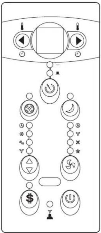
ELECTRONIC CONTROL OPERATING INSTRUCTIONS
NOTE: Different models have different control buttons and indicator lights. Not all the control buttons and indicator lights describing below are available for the unit you purchased. Please check the control panel of the unit you purchased. The unit can be controlled by the unit control alone or with the remote.
flowchart
graph TD
    A["User Interface"] --> B["Control Panel"]
    B --> C{Signal}
    C --> D["Switch Icon"]
    C --> E["Car Icon"]
    C --> F["Circle Icon"]
    C --> G["Balance Button"]
    C --> H["Reset Button"]
    C --> I["Send Signal"]
    C --> J["Send Reset"]
    C --> K["Send Pull Button"]
    C --> L["Send Dash Button"]
    C --> M["Send Dash Button"]
    C --> N["Send Dash Button"]
    C --> O["Send Dash Button"]
    C --> P["Send Dash Button"]
    C --> Q["Send Dash Button"]
    C --> R["Send Dash Button"]
    C --> S["Send Dash Button"]
    C --> T["Send Dash Button"]
    C --> U["Send Dash Button"]
    C --> V["Send Dash Button"]
    C --> W["Send Dash Button"]
    C --> X["Send Dash Button"]
    C --> Y["Send Dash Button"]
    C --> Z["Send Dash Button"]
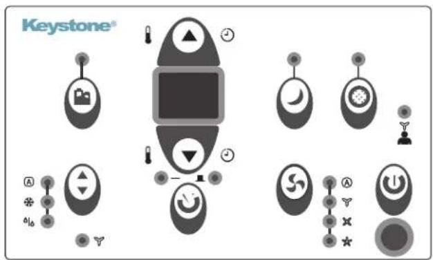
TO TURN UNIT ON OR OFF:
Press ⏻ POWER button to turn unit on or off.
NOTE: The unit will initiate automatically the Energy Saver function under Cool, Dry and Auto modes.
TO CHANGE TEMPERATURE SETTING:
Press ◀/▶ or ▲/▼ UP/DOWN button to change temperature setting.
NOTE: Press or hold either UP or DOWN button until the desired temperature is shown on the display.
This temperature will be automatically maintained anywhere between 62°F (17°C) and 86°F (30°C).
If you want the display to read the actual room temperature, see "To Operate on Fan Only" section.
SLEEP FEATURE:
Press 🚗 sleep button to initiate the sleep mode. In this mode the selected temperature will increase (cooling) or decrease (heating) by 2°F/1 (or 2)°C 30 minutes after the mode is selected. The temperature will then increase (cooling) or decrease (heating) by another 2°F/1 (or 2)°C after an additional 30 minutes. This new temperature will be maintained for 6 or 7 hours before it returns to the originally selected temperature. This ends the sleep mode and the unit will continue to operate as originally programmed. The sleep mode program can be cancelled at any time during operation by pressing the sleep button again.
TO ADJUST FAN SPEEDS:
Press 🚫 Fan button to select the Fan Speed in four steps: Ⓐ Auto, ✕ Low, ✗ Med or ★ High. Each time thebutton is pressed, the fan speed mode is shifted. For some models, the fan speed can not beadjusted.
CHECK FILTER FEATURE:
Press ☐ Check filter button to initiate theis feature. This feature is a reminder to clean the Air Filter for more efficient operation. The LED (light) will illuminate after 250 hours of operation. To resetafter cleaning the filter, press the Check Filter button and the light will go off.
ENERGY SAVER FEATURE:
Press \$ / Energy saver button to initiate this function. This function is available on COOL, DRY, AUTO (only AUTO-COOLING and AUTO-FAN) modes. The fan will continue to run for 3 minutes after the compressor shuts off. The fan then cycles on for 2 minutes at 10 minute intervals until the room temperature is above the set temperature, at which time the compressor turns back on and Cooling Starts.
FOLLOW ME FEATURE:

This feature can be activated from the remote control ONLY. The remote control serves as a remote thermostat allowing for the precise temperature control at its location.
To activate the Follow Me feature, point the remote control towards the unit and press the Follow Me button. The remote display is actual temperature at its location. The remote control will send this signal to the air conditioner every 3 minutes interval until press the Follow Me button again. If the unit does not receive the Follow Me signal during any 7 minutes interval, the unit will beep to indicate the Follow Me mode has ended.
To choose operating mode, press ⬆ Mode button. Each time you press the button, a mode is selected in a sequence that goes from Ⓞ Auto, ✦ Cool, ⬇ Dry and ⭕ Fan. The indicator light beside will be illuminated and remained on once the modes selected. The unit will initiate automatically the EnergySaver function under Cool, Dry, Auto (only Auto-Cooling and Auto-Fan) modes. To operate on COOL mode:
- Choose CoolMode to set the cooling function. Use the Up and Down buttons to choose the desired temperature. WhenCool Mode is selected, the fan speed can be adjusted by pressing the fan button.
To operate on Auto feature:
- When you set the air conditioner in AUTO mode, it will automatically select cooling, or fan only operation depending on what temperature you have selected and the room temperature.
- The air conditioner will control room temperature automatically round the temperature point set by you.
- In this mode, the fan speed cannot be adjusted, it starts automatically at a speed according to the room temperature.
To operate on Fan Only:
- Use this function only when cooling is not desired, such as for room air circulation or to exhaust stale air (on some models). (Remember to open the vent during this function, but keep it closed during cooling for maximum cooling efficiency.) You can choose any fan speed you prefer.
- During this function, the display will show the actual room temperature, not the set temperature as in the cooling mode.
- In Fan only mode, the temperature is not adjusted. To operate on Dry mode:
- In this mode, the air conditioner will generally operate in the form of a dehumidifier. Since the conditioned space is a closed or sealed area, some degree of cooling will continue. On Dry mode, the fan speed is controlled at Low automatically.
TIMER: AUTO START/STOP FEATURE:
- Press 🕒 Timer button, the TIMER ON or TIMER OFFindicator light illuminates. It indicates the Auto Start or Auto Stop program is initiated. For some units, keep pressing the Timer button will cancel the timer settings.
- Press or hold the UP or DOWN button to change the Auto time by 0.5 hour increments, up to 10 hours, then at 1 hour increments up to 24 hours. The control will count down the time remaining until start.
- The selected time will register in 5 seconds, and the system will automatically revert back to display the previous temperature setting or room temperature when the unit is on.(when the unit is off, there is no display.)
- Turning the unit ON or OFF at any time or a djusting the timer setting to 0.0 will cancel the Auto Start/Stop timed program.
DISPLAYS:
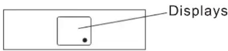
Shows the set temperature in "°C" or "°F" and the Auto-timer settings. While on Fan only mode, it shows the room temperature. If the room temperature is too high or low, it will display "HI" or "LO".
Error codes:
AS - Room temperature sensor error ES - Evaporator temperature sensor error
NOTE: " • " is displayed as shown in the above picture.
CS -Condenser temperature sensor error OS -Outside temperature sensor error E7 -Unit malfunction
NOTE: When error occurs, unplug the unit and plug it back in. If error repeats, call for service.

NOTE:
If the unit breaks off unexpectedly due to the power cut, it will restart with the previous function setting automatically when the power resumes.
ADDITIONAL THINGS YOU SHOULD KNOW
Now that you have mastered the operating procedure, here are more features in your control that you should become familiar with.
- The Cool circuit has an automatic 3 minutes time delayed start if the unit is turned off and on quickly.
This prevents overheating of the compressor and possible circuit breaker tripping. The fan will continue to run during this time. - The control is capable of displaying temperature in degrees Fahrenheit or degrees Celsius. To convert from one to the other, press and hold the Up and Down buttons at the same time for 3 seconds.
Care and Cleaning

CAUTION
Clean your air conditioner occasionally to keep it looking new. Be sure to unplug the unit before cleaning to prevent chock or fire hazards.
Air Filter Cleaning
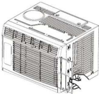
natural_image
Line drawing of an air conditioner unit with cooling fins and ventilation slots (no text or symbols)For 5000 Btu/h
Remove the filter by sliding out from the right-hand side.
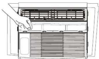
natural_image
Line drawing of a hand opening a large air conditioner unit with cooling fins (no text or symbols)For 6000 to 14000 Btu/h
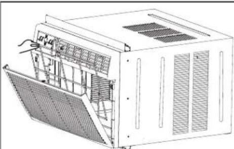
natural_image
Technical line drawing of a modular air conditioner unit with ventilation grilles and cooling fins (no text or symbols)For 18000 and 25000 Btu/h
The air filter should be checked at least once a month to see if cleaning is necessary. Trapped particles in the filter can build up and cause an accumulation of frost on the cooling coils.
- Push the vent handle to the Vent Closed position (where applicable). Open the front panel.
• Take the filter by the center and pull up and out. - Wash the filter using liquid dishwashing detergent and warm water. Rinse filter thoroughly. Gently shake excess water from the filter. Be sure the filter is thoroughly dry before replacing. Instead of washing, you may vacuum the filter clean.
Note: Never use hot water over 40^ C ( 104^ F) to clean the air filter. Never attempt to operate the unit without the air filter.
Cabinet Cleaning
- Be sure to unplug the air conditioner to prevent shock or fire hazard. The cabinet and front may be dusted with an oil-free cloth or washed with a cloth dampened in a solution of warm water and mild liquid dishwashing detergent. Rinse thoroughly and wipe dry.
- Never use harsh cleaners, wax or polish on the cabinet front.
- Be sure to wring excess water from the cloth before wiping around the controls.
Excess water in or around the controls may cause damage to the air conditioner.
- Plug in air conditioner.
Winter Storage
If you plan to store the air conditioner during the winter, remove it carefully from the window according to the installation instructions. Cover it with plastic or return it to the original carton.
TROUBLESHOOTING TIPS
Before calling for service, review this list. It may save your time and expense. This list includes common occurrences that are not the result of defective workman-ship or materials in this appliance.
| Problem Solution | |
| Air conditioner does not start | Wall plug disconnected. Push plug firmly into wall outlet. |
| House fuse blown or circuit breaker tripped. Replace fuse with time delay type or reset circuit breaker. | |
| Plug Current Device Tripped. Press the RESET button. | |
| Power is OFF. Turn power ON. | |
| Air from unit does not feel cold enough | Room temperature below 62°F(17°C). Cooling may not occur until room temperature rises above 62°F(17°C). |
| Temperature sensing behind air filter element touching cold coil. Keep it from the cold coil. | |
| Set to a Lower temperature. | |
| Compressor stopped when changing modes. Wait for 3 minutes after set to the COOL mode. | |
| Air conditioner cooling, but room is too warm- ice forming on cooling coil behind decorative front. | Outdoor temperature below 64°F(18°C). To defrost the coil, set FAN ONLY mode. |
| Air filter may be dirty. Clean filter. Refer to Care and Cleaning section. To defrost, set to FAN ONLY mode. | |
| Thermostat set too cold for night-time cooling. To defrost the coil, set to FAN ONLY mode. Then, set temperature to a Higher setting. | |
| Air conditioner cooling, but room is too warm- NO ice forming on cooling coil behind decorative front. | Dirty air filter- air restricted. Clean air filter. Refer to Care and Cleaning section. |
| Temperature is set too High, set temperature to a Lower setting. | |
| Air directional louvers positioned improperly. Position louvers for better air distribution. | |
| Front of units is blocked by drapes, blinds, furniture, etc. - restricts air distribution. Clear blockage in front of unit. | |
| An open doors, windows,or register may allow cold air to escape. Close any doors, winows, or registers. | |
| The room may be too warm. Allow additional time to remove “Stored heat” from walls, ceiling, floor and furniture. | |
| Air conditioner turns on and off rapidly | Dirty air filter- air restricted. Clean air filter. |
| Outside temperature extremely hot. Set FAN speed to a Higher setting to bring air past cooling coils more frequently. | |
| Noise when unit is cooling | Air movement sound. This is normal. If too loud, set to a slower FAN setting. |
| Window vibration - poor installation. Refer to installation instructions or check with installer. | |
| Water dripping INSIDE when unit is cooling. | Improper installation. Tilt air conditioner slightly to the outside to allow water drainage. Refer to installation instructions - check with installer. |
| Water dripping OUTSIDE when unit is cooling. | Unit removing large quantity of moisture from humid room. This is normal during excessively humid days. |
| Remote Sensing Deactivating Prematurely (some models) | Remote control not located within range. Place remote control within 20 feet and pointed in the general direction of the air conditioner unit. |
| Remote control signal obstructed. Remove obstruction. | |
| Room too cold | Set temperature too low. Increase set temperature |
The design and specifications are subject to change without prior notice for product improvement. Consult with the sales agency or manufacturer for details. Any updates to the manual will be uploaded to the service website, please check for the latest version.
natural_image
Line drawing of an air conditioning unit with ventilation grilles and control panel (no text or labels)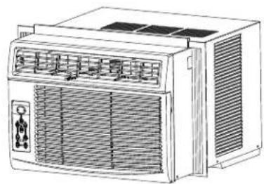
natural_image
Line drawing of an air conditioner unit with ventilation grilles and control panel (no text or symbols)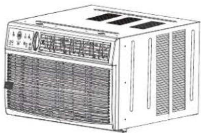
natural_image
Line drawing of a white industrial air conditioner unit with ventilation grilles and fan (no text or symbols)Modelo: KSTAW05DE KSTAW12CE
KSTAW06CE KSTAW14DE
KSTAW08CE KSTAW18C
KSTAW10DE KSTAW25C
NOTA IMPORTANTE:

https://keystone-products.com/register-your-product

natural_image
Line drawing of an air conditioner unit with cooling fins and ventilation slots (no text or labels)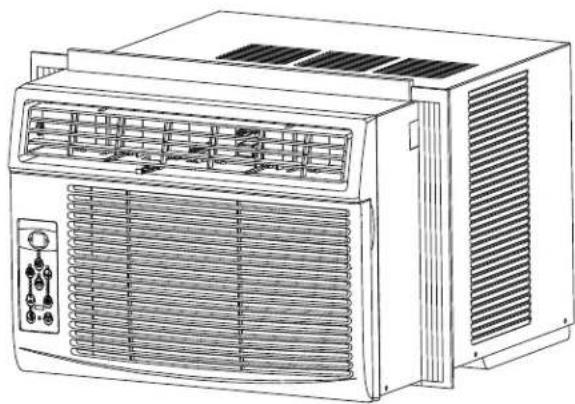
natural_image
Line drawing of an air conditioner unit with ventilation grilles and control panel (no text or symbols)
natural_image
Line drawing of a white HVAC air conditioner unit with ventilation grilles and ventilation grilles (no text or symbols)
NOTA:
natural_image
Technical line drawing of a modular device labeled Fig.B, showing internal components and ventilation ducts (no text or symbols on the device itself)natural_image
Technical line drawing of an air conditioner unit (no text or symbols)natural_image
Simple line drawing of a vertical corrugated structure with an arrow indicating left motion (no text or symbols)natural_image
Pure technical line drawing of a mechanical assembly without any text, numbers, or symbolsFig.2
natural_image
Technical line drawing of a window frame structure with no visible text or symbolsFig.7A Fig.7B
6 CONDUZCA TORNILLOS DE BLOQUEO
natural_image
Hand holding a pen inside a vehicle or storage unit (no visible text or symbols)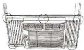
natural_image
Architectural diagram of a building facade with vertical supports and a central door (no text or symbols)Fig.8A Fig.8B
natural_image
Line drawing of a hand using a tool to install or install a mechanical component (no text or symbols present)Fig.9
7 INSTALE EL HARDWARE R1 (solo applicable a ≥15000Btu/h)
natural_image
Diagram of a mechanical device with a downward arrow indicating a process or operation (no text or symbols present)Fig.13
natural_image
Technical line drawing of a cabinet or enclosure with internal components and ventilation grilles, showing no text or symbols.Fig.14
natural_image
Pure technical diagram of an air conditioning unit with control panel and ventilation ducts (no text or symbols)Fig.1 Fig.2
natural_image
Technical line drawing of a computer case with an open panel and internal components (no text or symbols)Fig.4
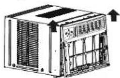
Fig.3A
natural_image
Simple line drawing of a mechanical or structural component with no text, numbers, or symbolsFig.6
Fig.15B
natural_image
Technical line drawing of a window frame with vertical bars and a separate handle (no text or symbols)Fig.18C
natural_image
Diagram of a mechanical device with a downward arrow indicating compression or disassembly (no text or symbols present)Fig.22
Fig.23
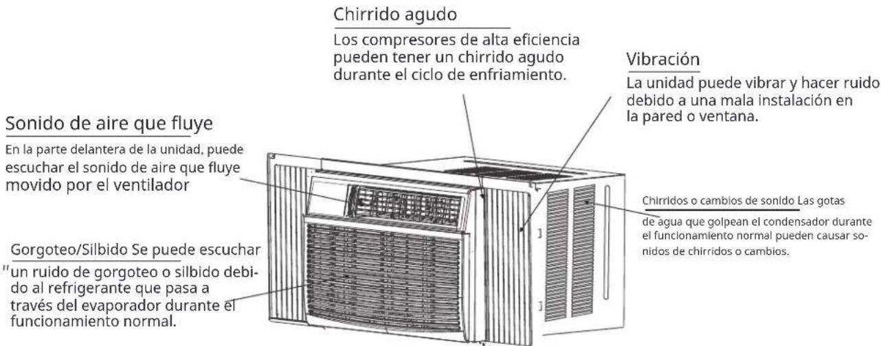
Sonidos normales
natural_image
Pure schematic diagram of a structural beam with arrows indicating direction (no text or symbols)Dirección del aire
Palancas
natural_image
Technical line drawing of a mechanical component with internal channels and dimension arrows (no text or symbols)Dirección del aire
Palancas
natural_image
Pure architectural floor plan lines without any text, numbers, or symbolsnatural_image
Pure architectural floor plan lines without any text, numbers, or symbolsnatural_image
Pure technical line drawing of a mechanical assembly without any text, numbers, or symbolsnatural_image
Diagram of a server rack with ports and connectors, no text or symbols present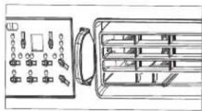
natural_image
Diagram of an electronic device panel with ports and connectors, showing front and side views (no text or symbols)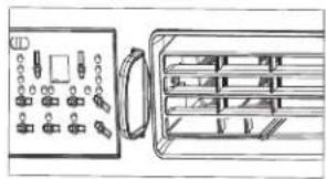
natural_image
Diagram of a device panel with ports and connectors, showing internal structure (no text or labels)natural_image
Line drawing of an air conditioner unit with cooling fins and ventilation slots (no text or symbols)Para 5000 Btu/h
natural_image
Line drawing of a hand opening a large air conditioner unit with cooling fins (no text or symbols)Para 6000 a 14000 Btu/h
natural_image
Technical line drawing of a modular air conditioner unit with ventilation grilles and cooling fins (no text or symbols)natural_image
Line drawing of an air conditioning unit with ventilation grilles and fan (no text or labels)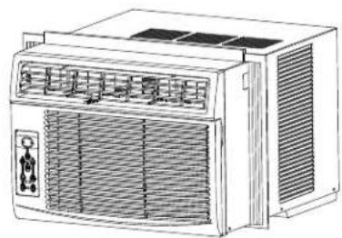
natural_image
Line drawing of an air conditioner unit with ventilation grilles and control panel (no text or symbols)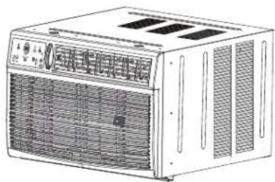
natural_image
Line drawing of a white electric air conditioner unit with ventilation grilles and control panel (no text or symbols)https://keystone-products.com/register-your-product

Information de garantie
FAITES TOUJOURS CECI
natural_image
Line drawing of an air conditioning unit with cooling fans and ventilation slots (no text or labels)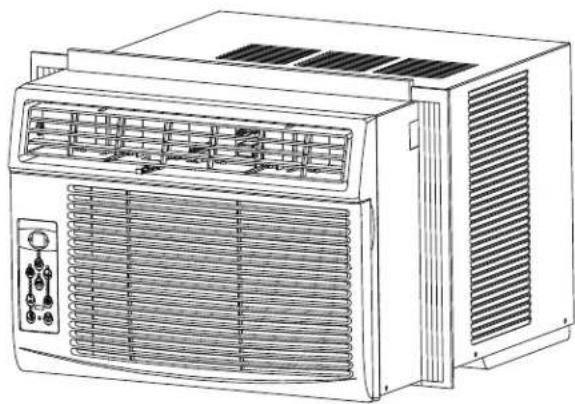
natural_image
Line drawing of an air conditioner unit with ventilation grilles and control panel (no text or symbols)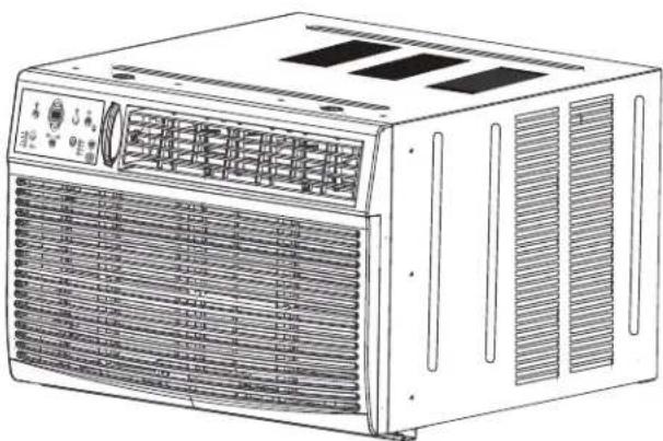
natural_image
Line drawing of an air conditioner unit with ventilation grilles and control panel (no text or symbols)
REMARQUE:
natural_image
Technical line drawing of a modular device labeled Fig.B, showing internal components and ventilation ducts (no text or symbols on the device itself)natural_image
Technical line drawing of a portable air conditioner unit (no text or symbols)natural_image
Simple line drawing of a vertical corrugated structure with an arrow pointing left (no text or symbols)natural_image
Technical line drawing of a mechanical assembly with no visible text or symbolsFig.2
natural_image
Technical line drawing of a window frame structure with no visible text or symbolsFig.7A Fig.7B
6 ENFONCER LES VIS DE VERROUILLAGE
natural_image
Technical line drawing showing a hand using a tool to adjust the door panel, with no visible text or symbols.Fig.8A Fig.8B
natural_image
Line drawing of a hand using a tool to install or install a mechanical component (no text or symbols present)Fig.9
natural_image
Diagram of a mechanical or electrical component with a downward arrow indicating direction, showing internal structure and housing (no text or symbols)Fig.13
natural_image
Technical line drawing of a multi-level HVAC unit with ventilation grilles and a zoomed-in inset showing airflow direction (no text or symbols)Fig.14
natural_image
Diagram of an air conditioner unit with control panel and ventilation ducts (no text or labels)Fig.1 Fig.2
natural_image
Technical line drawing of a computer case with an open panel and internal components (no text or symbols)Fig.3 Fig.4
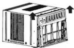
Fig.3A
natural_image
Simple line drawing of a mechanical setup with two vertical supports and a curved surface (no text or symbols)Fig.6
Fig.15B
natural_image
Technical line drawing of a mechanical bracket with ribbed texture and a separate clamp detail (no text or symbols)Fig.18C
natural_image
Simple diagram showing two scissors placed at the bottom of a vertical dashed line (no text or symbols)Fig.21

natural_image
Diagram of a mechanical device with internal components and a downward arrow indicating motion (no text or symbols)Fig.22
Fig.23
Bruit Normal
natural_image
Pure diagram of a structural beam with arrows indicating direction, no text or symbols presentDirection de l'air
Leviers
natural_image
Technical line drawing of a rectangular air vent with internal grid structure and directional arrows (no text or symbols)Direction de l'air
Leviers
natural_image
Pure architectural floor plan lines without any text, numbers, or symbolsFig. A (ORIFICES DE VENTILATION FERMÉS)
natural_image
Pure architectural floor plan lines without any text, numbers, or symbolsFig. B (ORIFICES DE VENTILATION OUVERTS) Fig. C (ORIFICES DE VENTILATION ET D'ÉVACUATION OUVERTS)
natural_image
Pure technical line drawing of a mechanical assembly without any text, numbers, or symbolsnatural_image
Diagram of an electronic device rear panel with ports and connectors (no text or labels)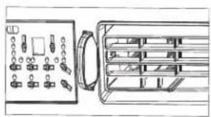
natural_image
Diagram of an electronic device rear panel with ports and connectors (no text or labels)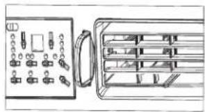
natural_image
Diagram of a device panel with ports and a separate output box (no text or symbols visible)Fig. A(ORIFICES DE VENTILATION FERMÉS) Fig. B(ORIFICES DE VENTILATION OUVERTS)
Fig. C (ORIFICES DE VENTILATION ET D'ÉVACUATION OUVERTS)
POUR ALLUMER OU ÉTEINDRE L'APPAREIL :
natural_image
Line drawing of an air conditioner unit with cooling fins and ventilation slots (no text or symbols)Pour 5000 Btu/h
natural_image
Line drawing of a hand opening a large air conditioner unit with cooling fins (no text or symbols)natural_image
Technical line drawing of a modular air conditioner unit with ventilation grilles and cooling fins (no text or symbols)- WINDOW TYPE ROOM AIR CONDITIONER
- User Manual
- IMPORTANT NOTE:
- Register your product today!
- Warranty Information
- Table of Contents
- Important Safety Instructions
- READ THIS MANUAL
- WARNING
- CAUTION
- NEVER DO THIS
- ALWAYS DO THIS
- NOTE:
- For Your Safety
- Prevent Accidents
- Electrical Information
- Operation of Current Device
- (Applicable to the unit adopts current detection device only)
- WARNING:
- WARNING for Using R32 Refrigerant
- Installation Instructions
- Installation Instructions (for 5000 to 14000Btu/h)
- BEFORE YOU BEGIN
- WINDOW REQUIREMENTS
- PREPARE THE WINDOW
- PREPARE AIR CONDITIONER
- INSTALL THE ACCORDION PANELS
- SECURE THE ACCORDION PANELS
- INSTALL SUPPORT BRACKET
- INSTALL R1 HARDWARE (only applicable to ≥15000Btu/h)
- INSTALL WEATHER STRIPPING
- If AC is Blocked by Storm Window
- Removing AC From Window
- Installation Instructions (for 18000 and 25000Btu/h)
- Remove Air Conditioner from Cabinet
- Install top angle and side Bracket
- Assemble Window Filler Panels
- Place Cabinet in window
- Extend Window Filler Panels
- Attach Window Filler Panels to Window Frame
- Install Window Sash Seal and Safety Lock
- Install Chassis into Cabinet and Install Front to Unit
- Install R1 HARDWARE (only applicable to ≥15000Btu/h models)
- Install WEATHER STRIPPING
- Normal Sounds
- Air Conditioner Features
- To begin operating the air conditioner, follow these steps:
- Air Directional Louvers
- Fresh Air Vent Control (for 10-14K MODELS)
- Fresh Air Vent Control (on 18K and 25K models):
- The Fresh Air Vent allows the air conditioner to:
- ELECTRONIC CONTROL OPERATING INSTRUCTIONS
- TO TURN UNIT ON OR OFF:
- TO CHANGE TEMPERATURE SETTING:
- SLEEP FEATURE:
- TO ADJUST FAN SPEEDS:
- CHECK FILTER FEATURE:
- ENERGY SAVER FEATURE:
- FOLLOW ME FEATURE:
- TIMER: AUTO START/STOP FEATURE:
- DISPLAYS:
- ADDITIONAL THINGS YOU SHOULD KNOW
- Care and Cleaning
- Air Filter Cleaning
- Cabinet Cleaning
- Winter Storage
- TROUBLESHOOTING TIPS
- NOTA IMPORTANTE:
- NOTA:
- CONDUZCA TORNILLOS DE BLOQUEO
- INSTALE EL HARDWARE R1 (solo applicable a ≥15000Btu/h)
- Sonidos normales
- Information de garantie
- FAITES TOUJOURS CECI
- REMARQUE:
- ENFONCER LES VIS DE VERROUILLAGE
- Bruit Normal
- POUR ALLUMER OU ÉTEINDRE L'APPAREIL :
Brand : Keystone
Model : KSTAW18C
Category : Air Conditioning