
VLP-2403 USB - Measuring equipment VOLTCRAFT - Free user manual and instructions
Find the device manual for free VLP-2403 USB VOLTCRAFT in PDF.

| Product Type | Laboratory Power Supply |
| Brand | Voltcraft |
| Model | VLP-2403 USB |
| Category | Measuring Equipment |
| Available Outputs | 2 adjustable laboratory outputs (0–40 V / 0.01–3 A), 1 adjustable USB output (4.0–6.2 V / 0–2.5 A), 1 automatic USB output (5 V/2.5 A, 9 V/2 A, 12 V/1.5 A) |
| Operating Modes (outputs A and C) | Independent (IND), Parallel (PAR), Series (SER), Tracking (TRCK) |
| Mains Voltage | 230 V/AC (±10%) 50 Hz |
| Max. Power Consumption | 590 VA |
| Mains Fuse | T3.15 A/250 V (5 x 20 mm) |
| Voltage Display Accuracy | ≤ ±(1% + 0.2 V) |
| Current Display Accuracy | ≤ ±(2% + 0.02 A) |
| Ripple & Noise (laboratory outputs) | ≤ 2 mV (at rated load) |
| Voltage Regulation (100% load) | ≤ 25 mV (outputs A/C) |
| Regulation Stability | 25 mV/h |
| Display | 2 lines, green 7-segment, 3 digits (12 mm) |
| Protection | Adjustable overvoltage protection (OVP), current limiting, overheat protection |
| Protection Class | 1 (grounded) |
| Dimensions (W x H x D) | 440 x 125 x 270 mm |
| Weight | 11.0 kg |
| Operating Temperature | +5 to +40 °C |
| Relative Humidity | 85% max., non-condensing |
| Maintenance and Cleaning | Clean with a dry, antistatic, lint-free cloth. Mains fuse replaceable. |
| Spare Parts and Repairability | Mains fuse (5x20 mm T3.15A/250V) replaceable by user. All other repairs to be carried out by a professional. |
| Safety | Use approved in dry premises. Do not cover ventilation openings. Disconnect before opening. |
Frequently Asked Questions - VLP-2403 USB VOLTCRAFT
User questions about VLP-2403 USB VOLTCRAFT
0 question about this device. Answer the ones you know or ask your own.
Ask a new question about this device
Download the instructions for your Measuring equipment in PDF format for free! Find your manual VLP-2403 USB - VOLTCRAFT and take your electronic device back in hand. On this page are published all the documents necessary for the use of your device. VLP-2403 USB by VOLTCRAFT.
USER MANUAL VLP-2403 USB VOLTCRAFT
GB Operating instructions
Laboratory power supply series VLP-USB
Item No. 1629369 VLP 1303 USB
Item No. 1629370 VLP 1405 USB
Item No. 1629371 VLP 1602 USB
Item No. 1629372 VLP 2403 USB Page 30 - 55
F Mode d'emploi
natural_image
Simple line drawing of a USB plug connected to a lamp (no text or symbols)5.5. Connecting a consumer 40
5.6. Technical specifications ....41
- VLP 2403 USB 42
6.1. Intended use 42
6.2. Product overview 43
6.2.1. Explanation of symbols 45
6.3. Functional description 45
6.4. Operation 45
6.4.1. Setting up the device....46
6.4.2. Connecting the mains cable....46
6.4.3. Switching on and setting the operating mode 46
6.4.4. Individual operation (IND) 46
6.4.5. Parallel operation (PAR)....48
6.4.6. Series operation (SER) 49
6.4.7. Tracking mode (TRCK) 50
6.4.8. USB output....51
6.5. Technical data 52
- Disposal....53
- Care and cleaning....53
8.1. Replacing the fuse 53
- Troubleshooting....54
1. Introduction
Dear customer,
Thank you for purchasing this Voltcraft® product.
Voltcraft ^® produces high-quality measuring, charging and network devices that offer outstanding performance and innovation.
With Voltcraft ^® , you will be able to cope with even the most difficult tasks whether you are an ambitious hobby user or a professional user. Voltcraft ^® offers you reliable technology at an extraordinarily favourable cost-performance ratio.
We are confident that starting to use Voltcraft® will also be the beginning of a long, successful relationship.
We hope you enjoy your new Voltcraft® product!
If there are any technical questions, please contact:
International: www.conrad.com/contact
United Kingdom: www.conrad-electronic.co.uk/contact
These operating instructions are part of this product. They contain important information on setting up and using the product. Do not give this product to a third party without the operating instructions.
Therefore, retain these operating instructions for reference!
2. Delivery content
• Laboratory power supply
- Power cord
- Operating instructions
Up-to-date operating instructions
Download the latest operating instructions via the link www.conrad.com/downloads or scan the QR code. Follow the instructions on the website.

3. Explanation of symbols
| The symbol with the lightning in a triangle indicates that there is a risk to your health, e.g. due to an electric shock. | |
| The symbol with an exclamation mark in a triangle is used to highlight important information in these operating instructions. Always read this information carefully. | |
| → | The arrow symbol indicates special information and advice on how to use the product. |
| Only to be used in dry indoor areas | |
| CE | This product has been CE tested and complies with the necessary national and European regulations. |
| ⊥ | Earth potential |
| Earth wire connection; this screw may not be loosened. | |
| The integrated isolating transformer is not short circuit-proof. The protective gear is switched downstream of the transformer (electrical overload and short-circuit protection). | |
| Caution - hot surface! Do not touch the surface. | |
| Read the operating instructions! |
4. Safety information
These instructions contain important information on how to use the device correctly. Please read them carefully before using the device for the first time.
Damage caused due to failure to observe these instructions will void the warranty. We shall not be liable for any consequential damage.
We shall not be liable for damage to property or personal injury caused by incorrect handling or failure to observe the safety information! Such cases will void the warranty/guarantee.
• This device was shipped in a safe condition.
- To ensure safe operation and to avoid damaging the device, always observe the safety information and warnings in these instructions.
- Electrical appliances and accessories are not toys and must be kept out of the reach of children!
- Always comply with the accident prevention regulations for electrical equipment when using the product in commercial facilities.
- Power supplies used in schools, training facilities, do-it-yourself and hobby workshops should not be handled unless supervised by trained, responsible personnel.
- Please make sure that your hands, your shoes, your clothing, the floor and the power supply are dry.
- Maintenance, adjustment or repair work may only be carried out by an expert/authorised service centre, who/which is familiar with the hazards involved and the relevant regulations.
- The unauthorised conversion and/or modification of the product is prohibited for safety and approval reasons. Do not open/disassemble! It contains no customer-serviceable parts.
- Live components may be exposed if covers are opened or parts are removed, unless this can be done by hand.
- Before opening, disconnect the device from all voltage sources. Capacitors inside the device may still be charged, even if the device has been disconnected from all voltage sources.
- Do not switch the laboratory power supply on immediately after it has been taken from a cold to a warm environment. The condensation generated may destroy the product in adverse conditions. Leave the device switched off and allow it to reach room temperature.
- The power supply will heat up during operation; ensure appropriate ventilation. Do not cover the ventilation apertures of the device! Do not touch the cooling element on the rear during operation. Risk of burns!
- Considering the wide variety of protective products used on furniture, there is a risk of chemical reaction with the surface. Place the device on a resistant, smooth and flat surface.
- Do not leave power supplies and connected consumers in operation unattended.
- Only use fuses of the rated type and current. Repaired fuses must not be used.
- Do not use non-insulated metallic leads.
- Working with power supplies while wearing metallic or conductive jewellery, such as necklaces, bracelets, rings, etc. is prohibited.
- The power supply is not designed for use on humans or animals.
- Never expose the device to mechanical stress. Dropping the device even from a low height may damage it! Avoid vibrations and direct sunlight.
- Do not place any vessels containing liquids on the device.
- Never pour liquids above or near the product. This constitutes a serious fire hazard and may result in a fatal electrical shock. If any liquid manages to enter the device, immediately switch off the power supply to the mains socket at which the product is connected (deactivate the fuse/circuit breaker/residual current operated circuit breaker of the associated circuits). Only then can you unplug the product from the mains socket and contact a specialist. Discontinue use of the product.
- Never use the product in a vehicle.
- If you suspect that safe operation is no longer possible, discontinue use immediately and prevent unauthorised use. Safe operation can no longer be assumed if:
- There are signs of damage
- The device does not function properly
- The device was stored under unfavourable conditions for a long period of time
- The device was subjected to rough handling during transport.
- You should also heed the additional safety instructions in each chapter of the operating instructions for the connected devices.
5.1. Intended use
- The laboratory power supply unit serves as a potential-free DC voltage source to operate low-voltage consumers. It has three independent outputs. An adjustable laboratory output, an adjustable USB output and a processor-controlled USB output.
- When switching the outputs of several power supplies in series, voltages of >70 V/DC may be generated, which are dangerous to touch. Above this voltage, insulated lines/measuring cables must be used for safety reasons. The devices are connected via 4 mm safety sockets.
- The output data of the laboratory power supplies is as follows:
| Item name Output A Output B1-USB Output B2-USB | |||
| VLP 1303 USB 0 - 30 V/DC0.01 - 3 A | 4.0 - 6.2 V/DC0 - 2.5 A | 5 V/DC, max. 2.5 A9 V/DC, max. 2.0 A12 V/DC, max. 1.5 A | |
| VLP 1405 USB 0 - 40 V/DC0.01 - 5 A | 4.0 - 6.2 V/DC0 - 2.5 A | 5 V/DC, max. 2.5 A9 V/DC, max. 2.0 A12 V/DC, max. 1.5 A | |
| VLP 1602 USB 0 - 60 V/DC0.01 - 1.5 A | 4.0 - 6.2 V/DC0 - 2.5 A | 5 V/DC, max. 2.5 A9 V/DC, max. 2.0 A12 V/DC, max. 1.5 A | |
- The voltage and current strength can be continuously adjusted at output A and B1-USB. The voltage and current values of output B1-USB are displayed with the push of a button on the display of output A.
- Output B2-USB is processor-controlled and always automatically selects the best output parameters for the terminal device connected.
- Voltage and current adjustments are via a precise adjuster. The voltage regulator for output A is a multi-turn potentiometer for precise settings. The values are displayed on a concise LC display.
- The current limitation for constant current mode can be preset with the push of a button. A short-circuit jumper at the output is not required during setting.
- For output A, a voltage limitation (OVP) can be set for safety purposes. When this adjustment level is achieved, the output is switched off automatically. This prevents the accidental destruction of connected consumers due to an excessively high output voltage.
- The device is overload and short-circuit-proof and contains a safety temperature cut-off.
- The laboratory power supply is designed in compliance with protection class 1. It is only approved for connection to protective sockets and an alternating current of 230 V/AC commonly used in households. The earth potential socket is directly connected to the protective earth on the mains plug.
- The mains socket to which the product is connected must be easily accessible.
- Operation under adverse ambient conditions is not permitted. Adverse conditions include: Damp or excessively high humidity, storms or stormy conditions such as strong electrostatic fields, etc.
-
Do not use the product in environments where there are high levels of dust, flammable gases, vapours or solvents. This may cause a fire or explosion!
-
Using this product for any purpose other than those described above may damage the product and result in a short-circuit, fire or electric shock. The product must not be modified or reassembled!
• Always observe the safety information in these instructions.
5.2. Product overview
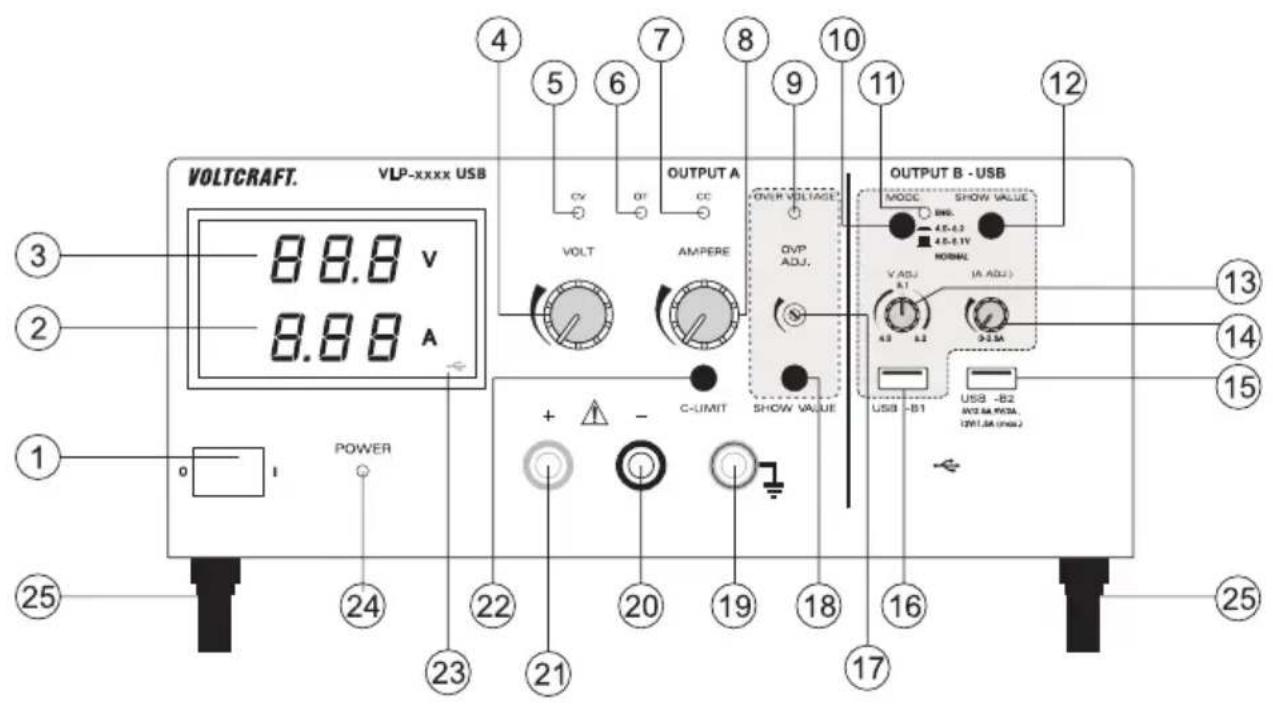
1 Power switch for putting the device into operation (I = ON / 0 = OFF)
2 Current display (A)
3 Voltage display (V)
4 Voltage adjuster for output A (VOLT)
5 Output A status display (CV = constant voltage)
6 Output A status display (OT = overtemperature)
7 Output A status display (CC = constant current)
8 Current adjuster for output A (AMPERE)
9 Status display when overvoltage cut-off active (OVER VOLTAGE)
10 Push switch for voltage range selection of output B USB-B1
11 Flashing status display while the push button (10) pressed in
12 Button for displaying the voltage and current of output USB-B1
13 Voltage adjuster for output B USB-B1 (V ADJ.)
14 Current adjuster for output B USB-B1 (A ADJ.)
15 Processor-controlled USB output B USB-B2
16 Adjustable USB output B USB-B1
17 Level adjuster for overvoltage cut-off (OVP ADJ.)
18 Button to display the set level for overvoltage cut-off
19 "Earth potential" connection socket
20 Negative of output A connection socket
21 Positive of output A connection socket
22 "C-LIMIT" button for displaying and setting the current limitation of output A
23 USB symbol indicates the display of output B USB-B1
24 Power indicator when the device is switched on
25 Feet on the front, folding
26 Rear heat sink
27 Fuse holder for the mains fuse
28 Earthed low-power connection for mains cable
5.2.1. Explanation of symbols
The following symbols appear on some controls.
| Button pressed symbol | Control range symbol. The arrow shows the direction of increase. | ||
| Button not pressed symbol |
5.3. Functional description
The laboratory power supply works with reliable and solid linear technology. This ensures a stable output voltage and the lowest interference voltages. The DC output voltages are isolated and feature protective isolation against the mains voltage. Secondarily, the DC connection is effected via two coloured safety sockets or two USB sockets type A.
The concise display show the voltage and current for output A (V = Volt = unit of electrical voltage, A = Ampere = unit of electrical current).
Output B1 is displayed via a button (12) on the display of output A.
The current condition of the power supply is indicated via light displays. Various protective mechanisms, e.g. overvoltage protection, overload protection, current limitation, overheating protection, etc. are built in for secure and reliable operation.
Cooling of the power supply is provided via the rear heat sink. This enables silent operation. Therefore, ensure sufficient air circulation.
The power supply can continuously adjust the output voltage and the output current of output A and USB-B1.
5.4. Operation

The laboratory power supply is not a charger. To charge batteries, use suitable chargers with a charging current cut-off.
The surface of the housing will heat up during extended operation. Warning! Risk of burns! Therefore, ensure that there is adequate ventilation of the power supply and never operate it partly or fully covered to avoid any damage.
When connecting a consumer, ensure that it is connected when the device is switched off. A switched on consumer can produce in sparks when connecting to the output sockets of the power supply, which in turn can damage the sockets or the connected cables and/or their terminals.
If your power supply is not required, disconnect it from the mains.
5.4.1. Setting up the device
- Place the laboratory power supply on a stable, level and robust surface. Ensure that ventilation openings in the housing are not covered.
The front feet of the device can be unfolded for easier display reading. They allow you to put the laboratory power supply into a tilted position.
5.4.2. Connecting the mains cable
- Connect the supplied earthing mains cable to the low-power device installation socket (28) on the power supply. Ensure a tight fit.
- Connect the mains cable to a protective socket with protective earthing.
- The mains socket must be easily accessible or an all-pole protective cut-off must be present.
5.4.3. Setting the output voltage of output A
- Disconnect devices connected to output A (20 and 21).
- Switch the power supply on at the power switch (1). The operating display (24) lights up and the current and voltage display appear on the display.
- Move the "AMPERE" current adjuster (8) to the centre position.
- The output voltage for output A can be set with the "VOLT" rotary control (4).
In normal mode, the device operates in constant voltage mode. This means that the power supply emits a constant, preset output voltage. This operation is indicated with a green status display "CV" (5).
5.4.4. Setting the current limitation of output A
Limiting the output current is a protective mechanism to protect the consumer or connecting cables. Current limitation can be preset without short-circuit at the output. The power supply supplies the maximum preset current.
- Disconnect devices connected to output A (20 and 21).
- Switch the power supply on at the power switch (1). The operating display (24) lights up and the current and voltage display appear on the display.
- Turn the "AMPERE" rotary control (8) fully to the left.
- Press and hold the "C-LIMIT" button (22) during setting. The output is switched off automatically when the "C-LIMIT" button is pressed. The voltage display then returns to 0.
- The max. current strength (current limitation) can be set with the "AMPERE" rotary control (8). After completing setting, release the "C-LIMIT" button. The display shows the actual current strength again (with output 0.00 A unloaded). The "CV" status display (5) lights up.
- Connect the consumer to output A (20 and 21) and switch it on. Pay attention to the polarity.
The “CC” LED display (7) lights up as soon as the set current level is exceeded and current limitation is active. Constant current mode is active.
If the preset current strength is reached in normal mode, the power supply switches to current limitation mode and reduces the voltage value. This operation is indicated with a red "CC" status display (7).
5.4.5. Setting the overvoltage protection (OVP) and resetting the device
Output A has adjustable overvoltage protection. This protective mechanism prevents the accidental destruction of connected consumers due to an excessively high output voltage. Upon reaching the preset safety level, output A is switched off immediately. Outputs B1 and B2 are not affected.
To set the safety level, proceed as follows
- With the laboratory power supply switched on, press and hold the "SHOW VALUE" button (18) during setting.
- The display (3) shows the current voltage level.
- Use an appropriate slotted screwdriver to set the desired max. voltage level on the "OVP ADJ." (17) adjuster. If you do not want a protective cut-off, turn the adjuster all the way to the right.
- Release the "SHOW VALUE" button (18). Overvoltage protection is activated.
Resetting OUTPUT A
As soon as the safety level set with the "VOLT" adjuster (4) has been exceeded, "OUTPUT A" switches off immediately. The voltage display (3) returns to approx. 0 V and the "OVER VOLTAGE" status display (9) lights up red.
- Disconnect the consumer from the laboratory power supply.
- Turn the "VOLT" adjuster a few turns anti-clockwise.
- Switch the laboratory power supply off and on again with the power switch (1). This resets the protective cut-off.
- Check the correct output voltage again and change the overvoltage protection, if necessary.
5.4.6. Setting the output voltage and current of output B USB-B1

Output B USB-B1 can be used independently of output A. It enables the USB-typical voltage of 5 V/DC variable from either 4.0 - 5.1 V/DC or 4.0 - 6.2 V/DC for development purposes. The current limitation can also be preset.
The setting range can be set with the "MODE" push button (10).
| Switch symbol Voltage range | ||
| Switch not pressed |  | 4.0 - 5.1 V/DC |
| Switch pressed“ENG” display (11) flashes. | [cc5s] | 4.0 - 6.2 V/DC |
- Disconnect consumers connected to output USB-B1 (16).
- Switch the power supply on at the power switch (1). The operating display (24) lights up and the current and voltage display appear on the display.
- Press and hold the "SHOW VALUE" button (12) while setting the voltage. The display of output A shows the voltage of output B USB-B1.

The USB symbol (23) lights up and indicates the display of the USB output.
- You can set the output voltage for output B USB-B1 with the "V ADJ." rotary control (13).
- You can adjust the current limitation for output B USB-B1 with the "AADJ." rotary control (14). Ensure the current value is high enough to not cutoff the voltage.
- After setting, release the "SHOW VALUE" button (12).
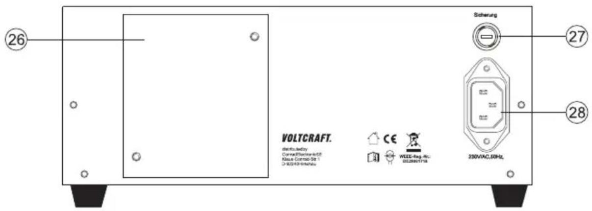
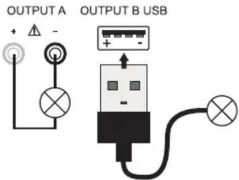
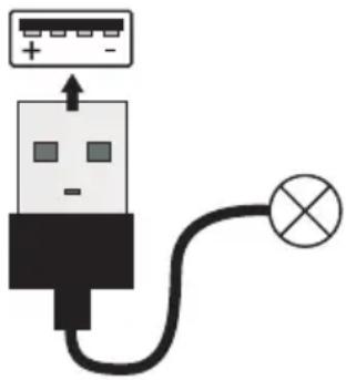
- Connect the consumer to output B USB-B1 (16) and switch it on. Pay attention to the polarity. The USB socket is switched by default. The diagram shows the contacts.

You can check the corresponding voltage and current values at any time by pressing the "SHOW VALUE" button (12).
5.4.7. Output B USB-B2
Output B USB-B2 is processor-controlled and is not adjustable. This output identifies the parameters of the connected terminal device and automatically sets the best possible settings for voltage and current.
Display of the current parameters is not possible.
5.5. Connecting a consumer

When connecting a consumer, ensure that it is connected to the power supply when switched off. The maximum current consumption of the device to be connected must not exceed the capacity indicated in the technical specifications.
When switching the outputs of several power supplies in series, voltages of >70 V/DC may be generated, which may be fatal if touched. Above of this voltage, you may only use insulated accessories (connection/measuring lines, etc.)
Avoid the use of non-insulated metallic cables and contacts. All of these bare spots must be covered with suitable, flame-resistant insulation materials or by means other measures to prevent direct contact and short-circuits.
Ensure a sufficient cable diameter for the intended current strength.
- Disconnect consumers connected to outputs A, B1 and B2.
- Switch the power supply on at the power switch (1). The operating display (24) lights up and the current and voltage display appear on the display.
- Set the parameters for outputs A and USB-B1 according to your specifications as outlined in the chapter "Operation".
- Verify again that the output voltage has been set correctly.
- At output A, connect the positive terminal (+) of the consumer to the red socket "+" and the negative terminal to the blue socket "-".
- At output B, connect the USB plug of the consumer to the USB socket.
- Now you can switch the connected consumer on.
5.6. Technical specifications
| VLP 1303 USB VLP 1405 USB VLP | 1602 USB | ||
| Output power 123 W 233 W 123 W | |||
| Output A output voltage 0 - 30 V/DC 0 - 40 V/DC 0 - 60 V/DC | |||
| Output A output current 0.01 - 3 A 0.01 - 5 A 0.01 - 1.5 A | |||
| V display accuracy ≤ ±(1% + 0.2 V) | |||
| A display accuracy ≤ ±(2% + 0.02 A) | |||
| Output voltage | 4.0 - 5.1 V/DC | ||
| Output B, USB-B1 | 4.0 - 6.2 V/DC | ||
| Output current | 0.01 - 2.5 A | ||
| Output B, USB-B2 | 5 V/DC, max. 2.5 A | ||
| Processor-controlled according to the connected consumers | 9 V/DC, max. 2.0 A | ||
| 12 V/DC, max. 1.5 A | |||
| Residual ripple at nominal load | |||
| Output A, USB-B1 | ≤2 mV | ||
| Output USB-B2 | ≤20 mV | ||
| Voltage control at 100% load change | OUTPUT A ≤25 mV | ||
| OUTPUT USB-B1 ≤20 mV | |||
| Voltage control at 10% mains fluctuation | OUTPUT A ≤20 mV | ||
| OUTPUT USB-B1 ≤15 mV | |||
| Current control at 100% load change | OUTPUT A ≤20 mA | ||
| OUTPUT USB-B1 ≤15 mA | |||
| Current control at 10% mains fluctuation | OUTPUT A ≤15 mA | ||
| OUTPUT USB-B1 ≤10 mA | |||
| Control stability | 15 mV/h | 25 mV/h | 25 mV/h |
| Display | Two-line, 12 mm, 3-digit 7-segment display, green | ||
| Operating voltage | 230 V/AC (±10%) 50 Hz | ||
| Power consumption (max.) | 290 VA | 490 VA | 270 VA |
| Slow-blow mains fuse (5 x 20 mm) | T1.6 A/250 V | T3.15 A/250 V | T1.6 A/250 V |
| Operating temperature | +5 to +40 °C | ||
| Rel. humidity | max. 85%, non-condensing | ||
| Protection class | 1 | ||
| Mains connection | Low-power device installation socket, IEC 320 C14 | ||
| Weight | 6.6 kg | 9.0 kg | 6.6 kg |
| Dimensions (W x H x D) mm | 260 x 115 x 270 | 350 x 125 x 260 | 260 x 115 x 270 |
6.1. Intended use
The laboratory power supply unit serves as a potential-free DC voltage source to operate low-voltage consumers. It has four independent outputs. Two adjustable laboratory outputs, an adjustable USB output and a processor-controlled USB output.
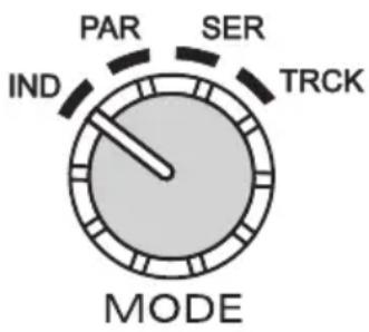
The two adjustable laboratory outputs can be operated via a mode selector switch in four different operating modes.
Individual (IND)
Each laboratory output (OUTPUT A and C) can be adjusted and used separately and independently. The device works as two separate laboratory power supplies.
Parallel (PAR)
The two laboratory outputs (OUTPUT A and C) are internally connected in parallel. Due to the parallel connection, the output current of the two outputs is added together. In this mode, the max. output current is 6 A. The output voltage is 40 V/DC.
Serial (SER)
The two laboratory outputs (OUTPUT A and C) are internally connected in series. Due to the series connection, the output voltage of the two outputs is added together. In this mode, the max. output voltage is max. 80 V/DC. The output current is max. 3 A.
Tracking (TRCK)
In tracking mode, the output voltage of the two laboratory outputs (Output A and C) is controlled via the VOLT-Master regulator of OUTPUT A. In this mode, the output voltage of the two outputs is always the same. The current limitation is set at the respective output.

When switching the outputs of several power supplies in series, voltages of >70 V/DC may be generated, which are dangerous to touch. Above this voltage, insulated lines/measuring cables must be used for safety reasons. The devices are connected via 4 mm safety sockets.
The output data of the laboratory power supply is as follows:
| Output A Output C Output B1-U | SB Output B2-USB | |
| 0 - 40 V/DC 0 | - 40 V/DC 4.0 - 5 | 1 V/DC 5 V/DC, max. 2.5 A |
| 0.01 - 3 A 0.0 | 1 - 3 A 4.0 - 6.2 V | DC 9 V/DC, max. 2.0 A |
| 0 - 2.5 A 12 V/DC, max. 1.5 A |
- The voltage and current strength can be continuously adjusted at output A, C and B1-USB. The voltage and current values of output B1-USB are displayed with the push of a button on the display of output C.
- Output B2-USB is processor-controlled and always automatically selects the best output parameters for the terminal device connected.
-
Voltage and current adjustments are via a precise adjuster. The voltage regulator for output A and C is a multi-turn potentiometer for precise settings. The values are displayed on two concise LC displays.
-
The current limitation for constant current mode can be preset at output A and C with the push of a button. A short-circuit jumper at the output is not required during setting.
- For output A and C, a voltage limitation (OVP) can be set for safety purposes. This can be set independently for the two outputs. When this adjustment level is achieved, the respective output is switched off automatically. This prevents the accidental destruction of connected consumers due to an excessively high output voltage.
- The device is overload and short-circuit-proof and contains a safety temperature cut-off.
- The laboratory power supply is designed in compliance with protection class 1. It is only approved for connection to protective sockets and an alternating current of 230 V/AC commonly used in households. The earth potential socket is directly connected to the protective earth on the mains plug.
- The mains socket to which the product is connected must be easily accessible.
- Operation under adverse ambient conditions is not permitted. Adverse conditions include: Damp or excessively high humidity, storms or stormy conditions such as strong electrostatic fields, etc.
- Do not use the product in environments where there are high levels of dust, flammable gases, vapours or solvents. This may cause a fire or explosion!
- Using this product for any purpose other than those described above may damage the product and result in a short-circuit, fire or electric shock. The product must not be modified or reassembled!
• Always observe the safety information in these instructions.
6.2. Product overview
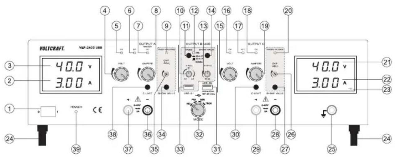
1 Power switch for putting the device into operation (I=ON/0=OFF)
2 Current display (A) for OUTPUT A
3 Voltage display (V) for OUTPUT A
4 Voltage adjuster (VOLT) for output A
5 Output A status display (CV = constant voltage)
6 Output A status display (OT = overtemperature)
7 Output A status display (CC = constant current)
8 Current adjuster (AMPERE) for output A
9 Status display when overvoltage cut-off active (OVER VOLTAGE) for output A
10 Voltage adjuster (V ADJ.) for output B USB-B1
11 Push switch for voltage range selection of output B USB-B1
12 Flashing status display while while the push button (11) pressed in
13 Current adjuster (A ADJ.) for output B USB-B1
14 Button for displaying the voltage and current setting of output USB-B1
15 Voltage adjuster (VOLT) for output C
16 Output C status display (CV = constant voltage)
17 Output C status display (OT = overtemperature)
18 Output C status display (CC = constant current)
19 Current adjuster (AMPERE) for output C
20 Status display when overvoltage cut-off active (OVER VOLTAGE) for output C
21 Voltage display (V) for OUTPUT C
22 Current display (A) for OUTPUT C
23 USB symbol indicates the display of output B USB-B1
24 Feet on the front, folding
25 "Earth potential" connection socket
26 Level adjuster for overvoltage cut-off (OVP ADJ.) for output C
27 Button to display the set level for overvoltage cut-off for output C
28 Negative of output C connection socket
29 Positive of output C connection socket
30 "C-LIMIT" button for displaying and setting the current limitation of output C
31 Processor-controlled USB output B USB-B2
32 "MODE" switch for selecting the operating mode
33 Adjustable USB output B USB-B1
34 Button to display the set level for overvoltage cut-off for output A
35 Level adjuster for overvoltage cut-off (OVP ADJ.) for output A
36 Negative of output A connection socket
37 Positive of output A connection socket
38 "C-LIMIT" button for displaying and setting the current limitation of output A
39 Power indicator when the device is switched on
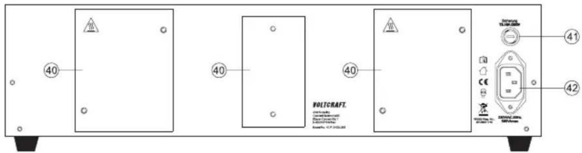
40 Rear heat sink
41 Fuse holder for the mains fuse
42 Earthed low-power connection for mains cable
6.2.1. Explanation of symbols
The following symbols appear on some controls.
| Button pressed symbol | Control range symbol. The arrow shows the direction of increase. | ||
| Button not pressed symbol |
6.3. Functional description
The laboratory power supply works with reliable and solid linear technology. This ensures a stable output voltage and the lowest interference voltages. The DC output voltages are isolated and feature protective isolation against the mains voltage. Secondarily, the DC connection is effected via two coloured safety sockets or two USB sockets type A.
The power supply can continuously adjust the output voltage and the output current of output A, C and USB-B1.
The 2 concise displays show the voltage and current for outputs A and C (V = Volt = unit of electrical voltage, A = Ampere = unit of electrical current).
Output USB-B1 is displayed via a button on the display of output C.
The current condition of the power supply is indicated via light displays. Various protective mechanisms, e.g. overvoltage protection, overload protection, current limitation, overheating protection, etc. are built in for secure and reliable operation.
Cooling of the power supply is provided via the rear heat sink. This enables silent operation. Therefore, ensure sufficient air circulation.
6.4. Operation

The laboratory power supply is not a charger. To charge batteries, use suitable chargers with a charging current cut-off.
The surface of the housing will heat up during extended operation. Warning! Risk of burns! Therefore, ensure that there is adequate ventilation of the power supply and never operate it partly or fully covered to avoid any damage.
When connecting a consumer, ensure that it is connected when the device is switched off. A switched on consumer can produce sparks when connecting to the output sockets of the power supply, which in turn can damage the sockets or the connected cables and/or their terminals.

If your power supply is not required, disconnect it from the mains.
The maximum current consumption of the device to be connected must not exceed the capacity indicated in the technical specifications.
When switching the outputs or several power supplies in series, voltages of >70 V/DC may be generated, which may be fatal if touched. Above this voltage, you may only use insulated accessories (connection/measuring lines, etc.)
Avoid the use of non-insulated metallic cables and contacts. All of these bare spots must be covered with suitable, flame-resistant insulation materials or by other measures to prevent direct contact and short-circuits.
Ensure a sufficient cable diameter for the intended current strength.
6.4.1. Setting up the device
- Place the laboratory power supply on a stable, level and robust surface. Ensure that ventilation openings in the housing are not covered.

The front feet of the device can be unfolded for easier display reading. They allow you to put the laboratory power supply into a tilted position.
6.4.2. Connecting the mains cable
- Connect the supplied earthing mains cable to the low-power device installation socket (42) on the power supply. Ensure a tight fit.
- Connect the mains cable to a protective socket with protective earthing.
- The mains socket must be easily accessible or an all-pole protective cut-off must be present (e.g. emergency-off switch).
6.4.3. Switching on and setting the operating mode
Four different operating modes for the two main laboratory outputs OUTPUT A and OUTPUT C can be set on the laboratory power supply.
Switch the power supply on at the power switch (1). The operating display (39) lights up and the voltage and current displays appear on both displays.
To select the operating mode, turn the "MODE" rotary control (32) to the corresponding position.

Before changing the function, ensure that no consumer is connected to output A or C. In the worst case, the consumer may be damaged due to overvoltage.
6.4.4. Individual operation (IND)
Each laboratory output (OUTPUT A and C) can be adjusted and used separately and independently. The device works as two separate laboratory power supplies. This is the default operating mode.
Setting the output voltage of output A and C
- Disconnect consumers connected to output A (36 and 37) and output C (28 and 29).
- Set the current adjuster for the respective output "AMPERE" (8 or 19) to the centre position.
- Use the "VOLT" rotary control (4 or 15) to set the output voltage.
- The voltage value "V" is indicated on the display (3 or 21)
In normal mode, the device operates in constant voltage mode. This means that the power supply emits a constant, preset output voltage. This operation is indicated with a green status display "CV" (5 or 16).
Setting the current limitation of output A or C
Limiting the output current is a protective mechanism to protect the consumer or connecting cables. Current limitation can be preset without short-circuit at the output. The power supply supplies the maximum preset current.
- Disconnect consumers connected to output A (36 and 37) and output C (28 and 29). Before setting the current limitation, always set the correct output voltage.
- Turn the "AMPERE" rotary control (8 or 19) fully to the left (neutral position).
- Press and hold the "C-LIMIT" button (30 or 38) during setting. The respective output is switched off automatically when the "C-LIMIT" button is pressed. The voltage display then returns to approx. 0.
- The max. current strength (current limitation) can be set with the "AMPERE" rotary control (8 or 19). After completing setting, release the "C-LIMIT" button. The display shows the actual current strength again (with output 0.00 A unloaded). The "CV" status display (5 or 16) lights up.
- Connect the consumer to output A (36 and 37) or output C (28 and 29) and switch it on. Pay attention to the polarity. The "CC" LED display (7 or 18) lights up as soon as the set current level is exceeded and current limitation is active. Constant current mode is active.
If the preset current strength is reached in normal mode, the power supply switches to current limitation mode and reduces the voltage value. This operation is indicated with a red "CC" status display (7 or 18).
Setting the overvoltage protection (OVP) and resetting the device
Outputs A and C have adjustable overvoltage protection. This protective mechanism prevents the accidental destruction of connected consumers due to an excessively high output voltage. Upon reaching the preset safety level, the respective output (A or C) is switched off immediately. The USB outputs are not affected.
To set the safety level, proceed as follows:
- With the laboratory power supply switched on, press and hold the "SHOW VALUE" button (34 or 27) during setting.
- The display (3 or 21) shows the current voltage level.
- Use an appropriate slotted screwdriver to set the desired max. voltage level on the "OVP ADJ." (35 or 26) adjuster. If you do not want a protective cut-off, turn the adjuster all the way to the right.
- Release the "SHOW VALUE" button (34 or 27). Overvoltage protection is activated.
Resetting output A or C:
- As soon as the safety level set with the "VOLT" adjuster (4 or 15) has been exceeded, the respective output A or C switches off immediately. The voltage display (3 or 21) returns to approx. 0 V and the "OVER VOLTAGE" status display (9 or 20) lights up red.
- Disconnect the consumer from the laboratory power supply.
- Turn the "VOLT" adjuster a few turns anti-clockwise.
- Switch the laboratory power supply off at the power switch (1). Wait for approx. 3 seconds and switch the device back on. This resets the protective cut-off.

Check the correct output voltage again and change the overvoltage protection, if necessary.
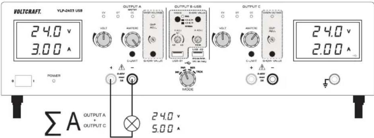
6.4.5. Parallel operation (PAR)
The two laboratory outputs (OUTPUT A and C) are internally connected in parallel. Due to the parallel connection, the output current of the two outputs is added together. In this mode, the max. output current is 6 A. The output voltage is 40 V/DC.
The internal wiring makes it possible to tap the max. output current of 6 A directly at output A. No external cable bridges are required.

Disconnect consumers connected to output A (36 and 37) and output C (28 and 29) before changing operating mode.
Setting the output voltage
- Use the "MODE" rotary control (32) to select the "PAR" operating mode.
- Move the "AMPERE" current adjusters (8 or 19) to the centre position.
- Use the "VOLT" rotary control (4 or 15) to set the output voltage. In the lower voltage range, turn both "VOLT" rotary controls (4 or 15) alternately to approx. 12V . From 12V , it is enough to set the voltage using the rotary control for output A.
- The voltage value "V" is displayed on the display (3 or 21). The two voltage displays (3 and 21) show the same voltage at the output and may not be added together.
In normal mode, the device operates in constant voltage mode. This means that the power supply emits a constant, preset output voltage. This operation is indicated with a green status display "CV" (5 or 16).
Setting the current limitation of output A or C
- Disconnect consumers connected to output A (36 and 37) and output C (28 and 29). Before setting the current limitation, always set the correct output voltage.
- Turn the "AMPERE" rotary control (8 or 19) fully to the left (neutral position).
- Press and hold the "C-LIMIT" button (30 or 38) during setting. The respective output is switched off automatically when the "C-LIMIT" button is pressed. The voltage display then returns to approx. 0.
- The max. current strength (current limitation) can be set with the "AMPERE" rotary control (8 or 19). After completing setting, release the "C-LIMIT" button. The display shows the actual current strength again (with output 0.00 A unloaded). The "CV" status display (5 or 16) lights up.
- Connect the consumer to output A (36 and 37) and switch it on. Pay attention to the polarity. The output currents of the two outputs add up and are bundled at output A.
The "CC" LED display (7 or 18) lights up at the respective output as soon as the set current level is exceeded and current limitation is active. Constant current mode is active.
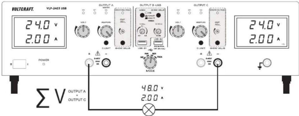
6.4.6. Series operation (SER)
The two laboratory outputs (OUTPUT A and C) are internally connected in series. Due to the series connection, the output voltage of the two outputs is added together. In this mode, the max. output voltage is max. 80 V/DC. The output current is max. 3 A.
The internal wiring makes it possible to tap the max. output voltage of 80 V directly via the two sockets at output A and C. No external cable bridges are required.

Disconnect consumers connected to output A (36 and 37) and output C (28 and 29) before changing operating mode.
Setting the output voltage
- On the "MODE" rotary switch (32), select the "SER" operating mode.
-
Move the "AMPERE" current adjusters (8 or 19) to the centre position.
-
Use the "VOLT" rotary control (4 or 15) to set the output voltage. Note that the two set voltages at the output are added together.
- The voltage values "V" are shown on the display (3 and 21) and must be added together. The sum of the voltage setting is output at both output sockets (37 and 28).
In normal mode, the device operates in constant voltage mode. This means that the power supply emits a constant, preset output voltage. This operation is indicated with a green status display "CV" (5 or 16).
Setting the current limitation
- Disconnect consumers connected to output A (36 and 37) and output C (28 and 29). Before setting the current limitation, always set the correct output voltage.
- Turn the "AMPERE" rotary control (8 or 19) fully to the left (neutral position).
- Press and hold the "C-LIMIT" button (30 or 38) during setting. The respective output is switched off automatically when the "C-LIMIT" button is pressed. The voltage display then returns to approx. 0.
- The max. current strength (current limitation) can be set with the "AMPERE" rotary control (8 or 19). After completing setting, release the "C-LIMIT" button. The display shows the actual current strength again (with output 0.00 A unloaded). The "CV" status display (5 or 16) lights up.
- Connect the consumer to the output sockets “+” of output A (37) and “-” of output C (28) and switch it on. Pay attention to the polarity. The output voltages of the two outputs add up and are bundled at an output.
The "CC" LED display (7 or 18) lights up at the respective output as soon as the set current level is exceeded and current limitation is active. Constant current mode is active.
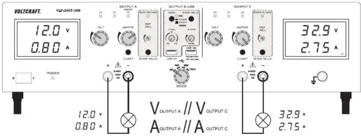
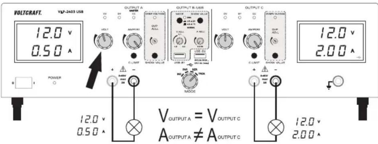
6.4.7. Tracking mode (TRCK)
In tracking mode, the output voltage of the two laboratory outputs (Output A and C) is controlled via the VOLT-Master regulator (4) of OUTPUT A. In this mode, the output voltage of the two outputs is always the same. The current limitation is set at the respective output.
Setting the output voltage
- Disconnect consumers connected to output A (36 and 37) and output C (28 and 29).
- Set the current adjuster for the respective output "AMPERE" (8 or 19) to the centre position.
-
In this operating mode, the voltage regulator at output C (15) must be set to maximum (right limit stop). This enables sole control via output A.
-
The output voltage for both outputs can be set with the "VOLT" rotary control (4) of output A.
- The voltage value "V" is displayed on the display (3 or 21).
In normal mode, the device operates in constant voltage mode. This means that the power supply emits a constant, preset output voltage. This operation is indicated with a green status display "CV" (5 or 16).
Setting the current limitation of output A or C
- Limiting the output current is a protective mechanism to protect the consumer or connecting cables. Current limitation can be preset without short-circuit at the output. The power supply supplies the maximum preset current.
- Disconnect consumers connected to output A (36 and 37) and output C (28 and 29). Before setting the current limitation, always set the correct output voltage.
- Turn the "AMPERE" rotary control (8 or 19) fully to the left (neutral position).
- Press and hold the "C-LIMIT" button (30 or 38) during setting. The respective output is switched off automatically when the "C-LIMIT" button is pressed. The voltage display then returns to approx. 0.
- The max. current strength (current limitation) can be set with the "AMPERE" rotary control (8 or 19). After completing setting, release the "C-LIMIT" button. The display shows the actual current strength again (with output 0.00 A unloaded). The "CV" status display (5 or 16) lights up.
- Connect the consumer to output A (36 and 37) or output C (28 and 29) and switch it on. Pay attention to the polarity.
- The "CC" LED display (7 or 18) lights up as soon as the set current level is exceeded and current limitation is active. Constant current mode is active.
If the preset current strength is reached in normal mode, the power supply switches to current limitation mode and reduces the voltage value. This operation is indicated with a red "CC" status display (7 or 18).
6.4.8. USB output
Two independent USB charging outputs are available. The settings and safety cut-offs of output A and C do not affect the two USB ports.
The output voltage and current limitation can be continuously adjusted at output USB-B1 (33).
The output parameters at output USB-B2 (31) are automatically processor-controlled for optimal setting according to the terminal device that is connected.
Setting the output voltage and current of output B USB-B1
Output B USB-B1 enables the USB-typical voltage of 5 V/DC variable from either 4.0 - 5.1 V/DC or 4.0 - 6.2 V/DC for development purposes. The current limitation can also be preset.
The setting range can be set with the "MODE" push button (11).
| Switch symbol Voltage range | ||
| Switch not pressed |  | 4.0 - 5.1 V/DC |
| Switch pressed “ENG” display (12) flashes. |  | 4.0 - 6.2 V/DC |
- Disconnect consumers connected to output USB-B1 (33).
- Press and hold the "SHOW VALUE" button (14) while setting the voltage. The display of output C shows the voltage of output B USB-B1.
- You can set the output voltage for output B USB-B1 with the "V ADJ." rotary control (10).
- You can adjust the current limitation for output B USB-B1 with the "A ADJ." rotary control (13) ensure the current value is high enough to not cutoff the voltage.
- After setting, release the "SHOW VALUE" button (14).
Connect the consumer to output B USB-B1 (33) and switch it on. Pay attention to the polarity. The maximum current value is 2.5 A, a current limit protection triggers automatically if exceeded for these outputs. The USB socket is switched by default. The diagram shows the contacts.
→ You can check the corresponding voltage and current values at any time by pressing the "SHOW VALUE" button (14).
OUTPUT B USB
natural_image
Simple line drawing of a USB plug connected to a lamp (no text or symbols)Output B USB-B2
Output B USB-B2 is processor-controlled and is not adjustable. This output identifies the parameters of the connected terminal device and automatically sets the best possible settings for voltage and current.
Display of the current parameters is not possible. Connection is to output B USB-B2 (31).
6.5. Technical data
| Output OUTPUT A OUTPUT C USB-B1 USB-B2 | ||||
| Output power 273 W | ||||
| Output voltage V/DC 0 - 40 V | (-200 mV ~ 41.5 V) | 0 - 40 V(-200 mV ~ 41.5 V) | 4.0 - 5.1 V4.0 - 6.2 V(-0.2 V/+0.1 V) | 5 V9 V12 V |
| Output current 0.01 - 3 A 0.01 - 3 A | 0.01 - 2.5 A max. 2 | 5 A | max. 2.0 Amax. 1.5 A | |
| Residual ripple at nominal load | ≤2 mV | ≤2 mV | ≤2 mV | ≤20 mV |
| Voltage control at 100% load change | ≤25 mV | ≤25 mV | ≤20 mV Not specified | |
| Voltage control at 10% mains fluctuation | ≤20 mV | ≤20 mV | ≤15 mV Not specified | |
| Current control at 100% load change | ≤20 mA | ≤20 mA | ≤15 mA | Not specified |
| Current control at 10% mains fluctuation | ≤15 mA | ≤15 mA | ≤10 mA | Not specified |
| Control stability | 25 mV/h | |||
| Display | Two-line,12 mm, 3-digit 7-segment display, green | |||
| V display accuracy | ≤±(1% + 0.2 V) | |||
| A display accuracy ≤±(2% + 0.02 A) | ||||
| Operating voltage 230 V/AC (±10%) | 50 Hz | |||
| Power consumption (max.) 590 VA | ||||
| Slow-blow mains fuse (5x 20 mm) T3, 15 A/250 V | ||||
| Operating temperature +5 to +40 °C | ||||
| Rel. humidity max. 85%, non-condensing | ||||
| Protection class 1 | ||||
| Mains connection Low-power device | installation socket, IEC 320 C14 | |||
| Weight 11.0 kg | ||||
| Dimensions (W x H x D) 440 x 125 x | 270 mm | |||
7. Disposal
Electronic devices are recyclable waste and must not be placed in household waste. At the end of its service life, dispose of the product according to the relevant statutory regulations.
8. Care and cleaning
Apart from an occasional cleaning or exchanging the fuse, this laboratory power supply is maintenance-free. Use a dry, clean, lint-free, antistatic cloth to clean the device. Do not use any abrasive or chemical agents or detergents containing solvents.
8.1. Replacing the fuse
If it is no longer possible to switch on the laboratory power supply, the rear mains fuse is probably defective.
Proceed as follows to replace the mains fuse:
- Switch the power supply unit off and remove all connecting cables from the device. Pull the mains plug from the mains socket.
- Using a suitable slotted screwdriver, depress the fuse holder on the rear a little, and remove it with a quarter-turn anticlockwise rotation (bayonet cap).
- Replace the defective fuse with a new fine-wire fuse (5 x 20 mm) of the same type and rated current: The fuse rating is listed in the technical specifications.
- While pushing, screw the fuse plug clockwise back into the fuse holder until it clicks into place.
9. Troubleshooting
By purchasing the laboratory power supply unit, you have acquired a product that is reliable and operationally safe.
However, problems and malfunctions may still occur.
This section explains how to troubleshoot common issues:

Always observe the safety information in these instructions.
Regularly check the technical safety of the device e.g. for damage to the housing, etc.

Any other repair work must always be carried out by qualified experts familiar with the hazards involved and with the relevant regulations. Unauthorised modifications or repairs to the device will invalidate the guarantee/warranty. Fuses are replacement parts and not covered by the warranty/guarantee!
| Error / Status display Possible cause | |
| The power supply does not switch on. | Is the power indicator on the power supply lit?Check the mains voltage (you may also want to check the mains fuse in the device or the line circuit breaker). |
| Connected consumers don't work. | Is the correct voltage set?Is the polarity correct?Check the technical specifications of the consumers.Is the overvoltage protection (OVP) active? |
| The “OT” display lights up. The power supply is overloaded and overheated.Allow the device to cool down while switched off. | |
| The “CC” display lights up. Constant current modeThe preset current was exceeded. Check power consumption on your consumer and increase the current limitation on your power supply, if necessary. | |
| The “CV” display lights up. No Error: Constant voltage modeThe power supply works normally. At the output, the set constant voltage is output. | |
| The “ENG” display flashes. | No error: status display. The large setting range of the output voltage was selected for USB-output USB-B1. The “MODE” switch is pressed. |
| VLP 1303 USB // VLP 1405 USB // VLP1602 USB | |
| The “OVER VOLTAGE” display lights up. | The preset level for overvoltage protection has been exceeded. Output A has been switched off.Reset the device as outlined in chapter “Resetting OUTPUT A” on page 39. |
| VLP 2403 USB | |
| The “OVER VOLTAGE” display lights up. | The preset level for overvoltage protection has been exceeded. OUTPUT A or OUTPUT C was switched off.Reset the device as outlined in chapter “Setting the overvoltage protection (OVP) and resetting the device” on page 47. |
| The “OVER VOLTAGE” display goes out after resetting (switch-off). | The switch-off time was too short.Leave the laboratory power supply off for at least 3 to 5 seconds.If the OVP display does not go out after a sufficient switch-off phase, please contact our service department. |
Page
- Introduction......57
- Contenu 57
- Explication des symboles ....58
- Consignes de sécurité ....59
- VLP 1303 USB // VLP 1405 USB // VLP 1602 USB ....61
France (email): technique@conrad-france.fr
natural_image
Simple line drawing of a USB plug connected to a lamp (no text or symbols)
- GB Operating instructions
- Laboratory power supply series VLP-USB
- F Mode d'emploi
- Introduction
- Delivery content
- Up-to-date operating instructions
- Explanation of symbols
- Safety information
- Intended use
- Product overview
- Explanation of symbols
- Functional description
- Operation
- Setting up the device
- Connecting the mains cable
- Setting the output voltage of output A
- Setting the current limitation of output A
- Setting the overvoltage protection (OVP) and resetting the device
- To set the safety level, proceed as follows
- Resetting OUTPUT A
- Setting the output voltage and current of output B USB-B1
- Output B USB-B2
- Connecting a consumer
- Technical specifications
- Intended use
- Individual (IND)
- Parallel (PAR)
- Serial (SER)
- Tracking (TRCK)
- Product overview
- Explanation of symbols
- Functional description
- Operation
- Setting up the device
- Connecting the mains cable
- Switching on and setting the operating mode
- Individual operation (IND)
- Setting the output voltage of output A and C
- Setting the current limitation of output A or C
- Setting the overvoltage protection (OVP) and resetting the device
- Resetting output A or C:
- Parallel operation (PAR)
- Setting the output voltage
- Series operation (SER)
- Setting the current limitation
- Tracking mode (TRCK)
- USB output
- Setting the output voltage and current of output B USB-B1
- Output B USB-B2
- Technical data
- Disposal
- Care and cleaning
- Replacing the fuse
- Troubleshooting
- Page
Brand : VOLTCRAFT
Model : VLP-2403 USB
Category : Measuring equipment