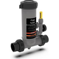
TruChlor Erosion Feeder - Pool Jandy - Free user manual and instructions
Find the device manual for free TruChlor Erosion Feeder Jandy in PDF.


| Product Type | Chlorine Erosion Feeder System |
| Brand | JANDY |
| Model | TruChlor Erosion Feeder |
| Category | Pool |
| Available Models | Inline and Offline |
| Chlorination Compatibility | Slow-dissolving Trichlor tablets (1" and 3") |
| Plumbing Compatibility | 2" or 2.5" PVC (inline); 1/2" flexible or rigid pipe (offline) |
| Operating Pressure | Pressurized system, safe opening |
| Minimum Flow Rate | 20 gpm (75.7 L/min) for variable speed version |
| Dimensions | Not specified (refer to installation manual) |
| Power Supply | None (mechanical via water flow) |
| Main Functions | Continuous chlorine dosing via erosion; adjustable control valve; flow indicator; easy draining for winterization |
| Maintenance | Regular cleaning of body and grid; lubricate O-ring with silicone only |
| Safety | DO NOT use calcium hypochlorite; DO NOT lubricate with oil/grease; wear protective equipment; do not install on copper; do not open under pressure |
| Spare Parts | Lid, O-ring, grid, control valve, flow indicator, variable speed insert kit, drain plug kit, etc. |
| Repairability | Cleaning and replacement of O-rings and valves possible |
| General Information | Installation by qualified professional; warranty void if incorrect installation; suitable for pools and spas |
Frequently Asked Questions - TruChlor Erosion Feeder Jandy
User questions about TruChlor Erosion Feeder Jandy
0 question about this device. Answer the ones you know or ask your own.
Ask a new question about this device
Download the instructions for your Pool in PDF format for free! Find your manual TruChlor Erosion Feeder - Jandy and take your electronic device back in hand. On this page are published all the documents necessary for the use of your device. TruChlor Erosion Feeder by Jandy.
USER MANUAL TruChlor Erosion Feeder Jandy
natural_image
Technical line drawing of a pressure regulator device with no visible text or symbols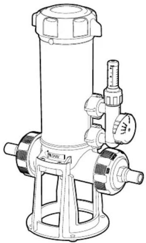
natural_image
Technical line drawing of a vertical pressure vessel with gauges and base mount (no text or symbols)TruChlor™ Erosion Feeder
In-Line, In-Line Variable Speed, Off-Line
! WARNING
If these instructions are not followed exactly, a fire or explosion may result, causing property damage, personal injury, or death.
FOR YOUR SAFETY: This product must be installed and serviced by a contractor who is licensed and qualified in pool equipment by the jurisdiction in which the product will be installed where such state or local requirements exists. In the event no such state or local requirement exists, the installer or maintainer must be a professional with sufficient experience in pool equipment installation and maintenance so that all of the instructions in this manual can be followed exactly. Before installing this product, read and follow all warning notices and instructions that accompany this product. Failure to follow warning notices and instructions may result in property damage, personal injury, or death. Improper installation and/or operation may void the warranty.
Table of Contents
Section 1. Important Safety Instructions......3
Section 2. Product Information ....4
In-Line / In-Line VS Version....4
Off-Line Version....5
Section 3. In-Line Installation....6
Section 4. Off-Line Installation....7
Connecting the Chlorinator....8
Connecting Dosing Tube To Pipe-work 9
Section 5. Operation....11
Section 6. Winterizing....13
Section 1. Important Safety Instructions
READ AND FOLLOW ALL INSTRUCTIONS
! DANGER
RISK OF FIRE OR EXPLOSION.
Only use slow dissolving Trichlor tablets in this chemical dosing unit and NEVER mix different chemical products together. Failure to observe the above warning could result in an explosion and fire.
NEVER use oils or grease to lubricate o-ring. Oil in contact with Trichlor may result in FIRE. Lubricate o-ring with approved silicone o-ring lubricant only. If you are not the original owner of this feeder, or not sure which chemical was used, be SAFE and flush thoroughly with fresh water. CAUTION SHOULD BE USED WHEN REMOVING CAP. DO NOT INHALE FUMES. IF YOUR POOL OR SPA HAS COPPER PLUMBING DO NOT INSTALL. This will damage the feeder. NOTE: If heaters are used, a Fireman's Switch or equivalent must be installed to prevent possible damage and improper operation of check valve and other equipment subject to heat damage.
CALCIUM HYPOCHLORITE IS NOT TO BE USED IN ANY FORM.
Never open the dosing unit lid when the unit is running. Before doing so, turn off the pool circulation pump and close all valves. Ensure you take the following precautions: Do not smoke in the vicinity of the unit, wear adequate eye and hand protection and avoid inhaling any gas that may be released. Apart from occasions when the unit needs to be re-filled or maintained, always ensure that the return line back to the pool is open to avoid the accumulation of any gases.
SAVE THESE INSTRUCTIONS
Section 2. Product Information
Before you begin installation, verify you have all necessary parts (See Tables 1 or 2 below, depending on model).
IN-LINE MODELS
| KIT PART NO. | COMPONENT DESCRIPTION QTY | ||
| 1 R0 | 966800 Cover 1 | ||
| 2 R0 | 966900 O-ring (Cover) 1 | ||
| 3,4 R0 | 966500 Grate and Check Valve Assembly 1 | ||
| 5 R0 | 966600 Replaceable Valve and Flow Indicator 1 | ||
| 6 R0 | 449000 Universal Union Assembly (Includes 2 Unions) 1 | ||
| 7 R0 | 967600 Drain Plug Kit 1 | ||
| 8,9 R0 | 967000 Variable Speed Insert Kit* - 3pcs (VS version only) 1 |
Table 1. In-Line Model Components
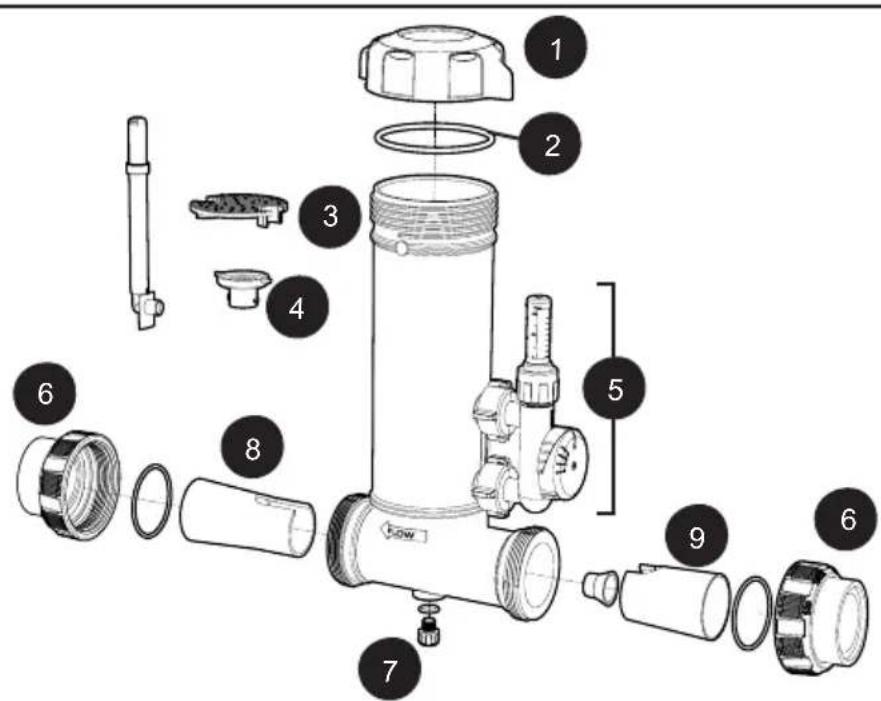
Figure 1. In-Line Components
*The TruChlor In-line VS feeder comes with the Low Flow Inlet, Cone and Outlet pre-installed. These are for systems with 2-speed or variable speed pumps where system flow is below 50 ~gpm at the low speed. If the system uses only a single speed pump, or the low speed is over 50 ~gpm , remove the inserts. Installations with Variable Speed pumps must be done using the Variable Speed Insert Kit. Minimum operating flow is 20 ~gpm .
OFF-LINE MODELS
| KIT PART NO. COMPONENT DESCRIPTION QTY | |||
| 1 | R0966800 Cover 1 | ||
| 2 | R0966900 O-ring (Cover) 1 | ||
| 3 | R0967100 Base Assembly 1 | ||
| 4,5 | R0966500 Grate and Check Valve Assembly 1 | ||
| 6 | R0966600 Replaceable Valve and Flow Indicator 1 | ||
| 7a | R0967200 Off-Line Hose Clamp Assy for Flexible Hose 2 | ||
| 7b | R0966700 Off-Line Hose Clamp Assy for Hard Pipe 2 | ||
| 8 | R0967600 Drain Plug Kit 1 | ||
| 9 | R0967300 Tubing Adapter and Union Nut Assembly 2 | ||
| 10 | R0976100 Off-line Tubing 1 | ||
Table 2. Off-Line Model Components
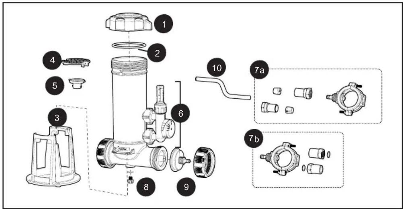
Figure 2. Off-Line Components
Section 3. In-line Installation
! CAUTION
DO NOT INSTALL chlorine feeder before the heating system. Damage to the heating system may occur.
WARNING
In order to prevent risk of serious property damage, injury or death: Wear eye and skin protection while maintaining or servicing this unit. Do not inhale fumes from the chlorinator or chemical container. Chlorine feeder may be under pressure. Use caution removing cover.
![12-5/8in [319mm] 16.0in [407mm] 14-15/16in [175mm] 20-1/8in [511.5mm] 14-3/16in [359.8mm] 6-3/16in [156.5mm] 7.5in [190mm] 5-1/8in [129.6mm] 4-3/8in [110mm]](/content/2026/04/677201/images/a65747eebdeb52dd3401c753d6d505de1d3f8165295512718e200043de9d9827.jpg)
Figure 3. Feeder Dimensions
- Install unit downstream of the filter and heater (if present).
IMPORTANT: Heaters and other equipment may be damaged by highly chlorinated water. A check valve should be installed before the erosion feeder to avoid damage to heater.
NOTE: For a pool/spa combo with 2" PVC plumbing and equipment, install the feeder on the pool return line after the diverter valve that diverts water to the spa. Then install a minimum section of 6" x 1.5" PVC pipe from the diverter valve into the inlet side of the feeder using 1.5" unions. Continue with 2" PVC pipe on the outlet side of the feeder. This will compensate for the water being diverted to the spa.
- Glue Jandy Universal Unions into 2" or 2 1/2" PVC pipe.
- When plumbing 90 degree elbows directly into the feeder inlet it may cause turbulence inside the elbow which prevents water from entering the feeder. A minimum of 6" PVC pipe should be installed between the elbow and the inlet of the feeder.
- Ensure valve nuts are hand tight.
- The arrows on feeder body should point in the direction of the water flow returning to thepool.
- Use only PVC cement. Follow the directions on the cement label. Allow time for the PVC cement to completely dry.
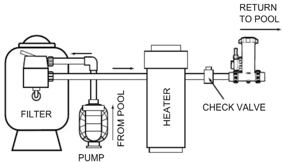
flowchart
graph LR
    A["FILTER"] --> B["PUMP"]
    B --> C["HEATER"]
    C --> D["CHECK VALVE"]
    D --> E["RETURN TO POOL"]
    style A fill:#f9f,stroke:#333
    style B fill:#ccf,stroke:#333
    style C fill:#cfc,stroke:#333
    style D fill:#fcc,stroke:#333
    style E fill:#ffc,stroke:#333
Figure 4. In-Line Installation Configuration
Section 4. Off-line Installation
- Position the dosing unit on a level surface as close to the filter and pump as possible. Do not install in copper plumbing.
- The base has holes at bottom for mounting to the pad floor (mounting hardware not included).
- Turn off the pump and timer switches.
-
The inlet connection must be made in the pipe-work after the pump and filter. This connection will feed water into the dosing unit.
-
The outlet connection must be made downstream of the heating system or, if no heating system is installed, downstream of the filter. This connection will be feeding treated water from the dosing unit into the plumbing system.
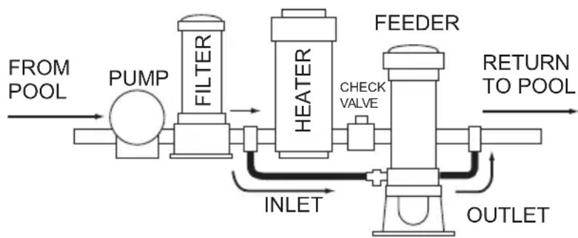
flowchart
graph LR
    A["FROM POOL"] --> B["PUMP"]
    B --> C["FILTER"]
    C --> D["HEATER"]
    D --> E["FEEDER"]
    E --> F["RETURN TO POOL"]
    D --> G["CHECK VALVE"]
    G --> H["INLET"]
    H --> I["OUTLET"]
INSTALLATION WITH HEATER
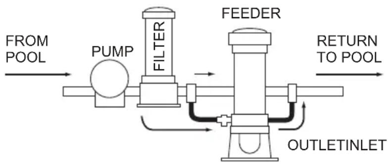
flowchart
graph LR
    A["FROM POOL"] --> B["PUMP"]
    B --> C["FILTER"]
    C --> D["FEEDER"]
    D --> E["RETURN TO POOL"]
    E --> F["OUTLETINLET"]
    F --> G["Return to POOL"]
INSTALLATION WITHOUT HEATER
Figure 5. Off-line Installation Configuration
- Flex pipe installation Use four compression nuts, four compression insert cones, and black flex tube, included with unit.
a. Cut the dosing tube to the required lengths, ensuring the cuts are clean, square and free of burrs.
b. Attach the inlet and outlet line to the feeder by installing the compression nut and cone over tubing. Push tubing onto the tapered end of the inlet. Tighten the nut firmly by hand (Figure 6).
c. Drill 3/4" hole in plumbing and remove any burrs.
d. Insert one plumbing nipple into the plumbing clamp for the inlet line. Install the clamp assembly for the inlet (line going TO feeder) and outlet (line FROM feeder) by installing the clamp assembly (Figure 7).
NOTE: Be sure the outlet connection is after the heater, filter, etc.
e. Install the remaining compression nuts and cones over the free ends of the tubing then push tubing onto tapered ends of the pipe nipples. Tighten the nuts firmly by hand.
- Hard pipe installation Use four 12 " socket nuts and four o-rings (included), and 12 " Sch 40 pipe (not included).
a. Thread on one 12 " socket nut to the feeder inlet barb and another to the outlet barb of the feeder. Be sure an o-ring is seated in the groove inside each socket nut.
b. Insert plumbing nipples into the plumbing clamps and secure with the remaining 12 " socket nuts. Be sure an o-ring is seated in the groove inside each socket nut.
c. Drill 3/4" hole in plumbing and remove any burrs.
d. Install clamp assembly over the plumbing where the 3/4" hole was drilled (Figure 7).
e. Use 12 " Sch 40 PVC pipe and fittings to connect the 12 " socket nuts at the plumbing to the 12 " socket nuts at the inlet and outlet.
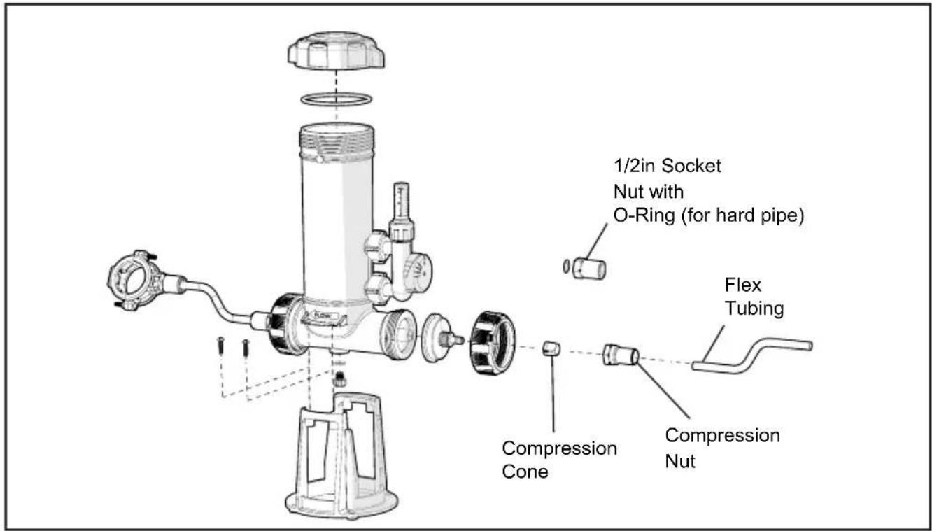
Figure 6. Connecting Hardware to Feeder
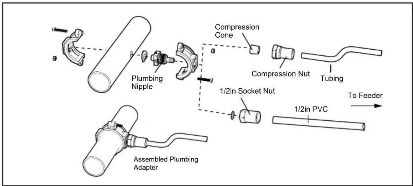
Figure 7. Connecting Hardware To Pipe
Section 5. Operation
NOTE: The consumption of chlorine in swimming pools varies according to use, temperature, exposure to sunlight, and other factors. Initially you will need to experiment with the control valve to ensure that the unit doses enough chemical to maintain an adequate residual. Start with the valve in the 50% position. Test the residual regularly using instructions below.
WARNING
Elevated Chemical Concentrations and Hazardous Gas - The introduction of potentially hazardous gas or elevated chemical concentrations into the pool or spa during backwash and periods of no flow in the circulation system may cause serious personal injury, or death. To avoid, use the following guidelines:
- Set dosage indicator to zero before stopping water flow through the chlorinator.
- Minimize backwash time.
- Do not shut off pump for extended periods.
-
Do not allow bathers into the pool or spa area until full flow through the circulation system has been established.
-
This tablet feeder is designed to help you maintain a chlorine residual. Always start a new feeder installation by ensuring that the chlorine is already at a proper residual level. Consult your local dealer for water conditioning information in your area. The residuals should be 1-3 ppm of free chlorine.
- Remove cap of feeder and fill with proper size tablets. For pools use 1" or 3" diameter tablets. For spas use 1" tablets.
- Completely fill body with water, and bleed out entrapped air in all system lines. Replace cap making sure o-ring is clean, lubricated with silicone lubricant and in place.
- Turn on pump and timer switches for a minimum of 6 to 8 hours. The water level inside chlorinator will be 3 – 5 inches under normal running conditions.
- Adjust the control valve counter-clockwise for more flow through the erosion feeder and more chlorine. Or adjust clockwise for less chlorine according to the size of the pool/spa. Use a test kit to determine the chemical residual. Check the chemical residual daily for the first five days.
NOTE: Hot weather, high water temperature and increased use will cause the pool/spa to use more chemical. Increase the feed rate a few days in advance when possible. The valve settings may require adjustment depending on the conditions.
NOTE: If the feeder does not provide enough chemical residual when using 3" tablets, switch to 1" tablets for faster erosion and increased residual.
NOTE: When maintaining the chlorinator, always check o-rings for damage, breaks, swelling, etc. Replace if necessary. (see Replacement Parts list)
Replacing Tablets
WARNING
In order to prevent risk of serious property damage, injury or death:
- Wear eye and skin protection while maintaining or servicing this unit.
- Do not inhale fumes from the chlorinator or chemical container.
-
Chlorine feeder may be under pressure. Use caution removing cover.
-
Shut off the pump and turn the control valve to the closed position. The check valve will prevent water from entering the feeder.
- Loosen cap but do not remove. Wait one minute to allow water and fumes to drain from feeder.
- Leave the control valve closed. Slowly remove the cap by tilting it away from yourself, such that any remaining gas that escapes is directed away from you. Check the position of the internal grate after each refilling. The grate may come out of its resting place when tablets are added to the chlorinator.
- Fill the feeder with tablets. NEVER MIX CHLORINE TABLET TYPES. DO NOT USE WITH CALCIUM HYPOCHLORITE OR BROMINE.
- Completely fill body with water, and bleed out entrapped air in all system lines.
- Replace cap making sure o-ring is clean, lubricated with silicone lubricant, and in place. Lubricate o-ring with approved silicone o-ring lubricant only. (Hand tighten only).
- To maintain knob range of motion and o-ring seal, fully rotate control valve before setting output level. Turn knob clockwise to 0 (closed), then counter-clockwise to 100 (fully open) and then open control valve to desired setting.
NOTE: Keep an eye on the tablet level in the unit, preferably reload BEFORE they run out.
WARNING
To avoid risk of property damage, serious injury or death, Calcium Hypochlorite is not to be used in any form.
Section 6. Winterizing
NOTE: If the equipment room or pool pad is subject to freezing conditions, it will be necessary to drain your dosing unit following these instructions.
- This chlorinator has a drain plug located on the bottom for easy draining of the unit for winter.
- Remove any remnants of undissolved chemical tablets and rinse out the body with clean water.
- Follow other normal procedures for your system to winterize.
Section 7. Troubleshooting
| SYMPTOM CAUSE CORRECTIVE ACTION | ||
| Glass lid is cloudy | Chlorine exposure Remove the lid and wipe clean. If it remains cloudy, it will clear itself if left exposed to sunlight and fresh air. DO NOT leave chlorinator open without the lid installed. If the lid must be left off to clear up, a replacement must be installed temporarily | |
| Reduced Flow / Low Chlorine / Flow Indicator Not Moving | Clogged valve assembly | Remove the replaceable valve assembly. It can be detached to clean any build-up or debris. |
| Clogged chlorinator body | The bottom grate can be removed when chlorine is gummed up inside the unit. The chlorine residue must be dislodged or it may affect feeder performance. The grate helps keep pieces of the tablets from clogging the outlet. | |
| Leaks around connections | Damaged o-rings Check o-rings for damage, replace as needed. | |
| Low chlorine concentration in the pool | 1. The trichlor tabs have been consumed2. Filtration time too low3. Chlorine demand too high | 1. Add trichlor tablets in the unit.2. Increase filtration daily time.3. If using 3" tabs, use 1" instead. |
| Water is green and/or algae is present | A water parameter is not properly maintained (pH, cyanuric acid, etc) | Contact your pool professional for more details and actions |
APPENDIX - SYSTEM PLUMBING
The diagrams below cover common plumbing configurations. For other configurations or installation questions, please call Technical Support.
- Erosion Feeder: Always plumb after pool heaters to prevent damage to the heater system. The feeder should be on the main return line, separate from waterfalls or auto cleaners.
• Alternative Sanitizer/ Ozone or AOP Systems. Always plumb feeders before any injectors to prevent gas or bubble build-up inside the erosion feeder.
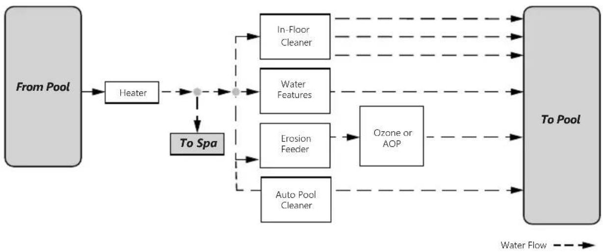
flowchart
graph LR
    A["From Pool"] --> B["Heater"]
    B --> C["To Spa"]
    C --> D["In-Floor Cleaner"]
    C --> E["Water Features"]
    C --> F["Erosion Feeder"]
    C --> G["Auto Pool Cleaner"]
    D --> H["To Pool"]
    E --> H
    F --> H
    G --> H
    H --> I["Water Flow"]
NOTES
Zodiac Pool Systems LLC
2882 Whiptail Loop # 100, Carlsbad, CA 92010, USA
Jandy.com | 1.800.822.7933
Zodiac Pool Systems Canada, Inc.
2-3365 Mainway, Burlington, ON L7M 1A6 Canada
Jandy.ca | 1.888.647.4004
©2022 Zodiac Pool Systems LLC. All rights reserved. ZODIAO® is a registered trademark of Zodiac International,
S.A.S.U., used under license. All other trademarks are the property of their respective owners. 1253
90010-252-900_Rev.A
Jandy®
natural_image
Technical line drawing of a pressure regulator device with no visible text or symbols
natural_image
Technical line drawing of a vertical flow pump with control unit and gauges (no text or symbols)Zodiac Pool Systems LLC
2882 Whiptail Loop 100, Carlsbad, CA 92010, USA
Jandy.com | 1.800.822.7933
Zodiac Pool Systems Canada, Inc.
2-3365 Mainway, Burlington, ON L7M 1A6 Canada
Jandy.ca | 1.888.647.4004
natural_image
Technical line drawing of a pressure regulator device with no visible text or symbols
natural_image
Technical line drawing of a vertical pressure vessel with attached gauges and base mount (no text or symbols)Zodiac Pool Systems LLC
2882 Whiptail Loop # 100, Carlsbad, CA 92010, EE. UU.
Jandy.com | 1.800.822.7933
Zodiac Pool Systems Canada, Inc.
2-3365 Mainway, Burlington, ON L7M 1A6 Canadá
Jandy.ca | 1.888.647.4004

- TruChlor™ Erosion Feeder
- ! WARNING
- Table of Contents
- Section 1. Important Safety Instructions......3
- Section 2. Product Information ....4
- Section 3. In-Line Installation....6
- Section 4. Off-Line Installation....7
- Section 5. Operation....11
- Section 6. Winterizing....13
- Section 1. Important Safety Instructions
- READ AND FOLLOW ALL INSTRUCTIONS
- ! DANGER
- RISK OF FIRE OR EXPLOSION.
- SAVE THESE INSTRUCTIONS
- Section 2. Product Information
- Section 3. In-line Installation
- ! CAUTION
- WARNING
- Section 4. Off-line Installation
- Section 5. Operation
- Replacing Tablets
- Section 6. Winterizing
- APPENDIX - SYSTEM PLUMBING
- NOTES
- Jandy®
Brand : Jandy
Model : TruChlor Erosion Feeder
Category : Pool