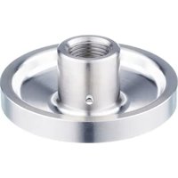
E43920 - Industrial sensor IFM - Free user manual and instructions
Find the device manual for free E43920 IFM in PDF.


User questions about E43920 IFM
0 question about this device. Answer the ones you know or ask your own.
Ask a new question about this device
Download the instructions for your Industrial sensor in PDF format for free! Find your manual E43920 - IFM and take your electronic device back in hand. On this page are published all the documents necessary for the use of your device. E43920 by IFM.
USER MANUAL E43920 IFM
Operating instructions
Welding adapters for devices with G1/2 hygiene fitting
Contents
1 Preliminary note.... 3
1.1 Symbols used.... 3
1.2 Warnings.... 3
2 Safety instructions 4
3 Transport, handling and storage 5
4 Intended use 6
4.1 Selection guide welding adapter 6
4.2 Basic notes 8
5 Installation.... 10
5.1 Preparation welding adapter and wall 10
5.2 Alignment of adapter / leakage port 10
5.3 Cooling 11
5.3.1 Cooling adapter E43929 11
5.3.2 Welding process with cooling adapter E43929 12
5.4 Welding process in general.... 13
5.5 Processing the weld seam.... 14
5.5.1 Processing special welding adapter.... 15
5.5.1.1 Installation of E43923 on the special welding adapter E43918.... 15
5.5.1.2 Installation of E43924 on the special welding adapter E43919.... 15
5.5.1.3 Installation of E43923 on the special welding adapter E43920.... 16
5.5.1.4 Processing of the weld seam for special welding adapters.... 16
5.6 Leak check 17
5.6.1 Leak check with test adapter E43922.... 17
5.6.2 Leak check of complete system 18
6 Install the sensor with G1/2 hygienic fitting.... 19
7 Set-up 20
8 Cleaning and maintenance when used in 3-A applications.... 21
9 Disposal 22
1 Preliminary note
You will find instructions, technical data, approvals and further information using the QR code on the unit / packaging or at documentation.ifm.com.
1.1 Symbols used
√ Requirement
Instruction
Reaction, result
bold Designation of keys, buttons or indications
→ Cross-reference without link
→ Cross-reference with link

Important note
Non-compliance may result in malfunction or interference

Information
Supplementary note
1.2 Warnings
Warnings indicate the possibility of personal injury and damage to property. This enables safe product handling. Warnings are graded as follows:

WARNING
Warning of serious personal injury
▷ If the warning is not observed, fatal and serious injuries are possible.

CAUTION
Warning of minor to moderate personal injury
▷ If the warning is not observed, minor to moderate injuries are possible.

ATTENTION
Warning of damage to property
▷ If the warning is not observed, damage to property is possible.
2 Safety instructions
- The unit described is a subcomponent for integration into a system.
- The system architect is responsible for the safety of the system.
-
The system architect undertakes to perform a risk assessment and to create documentation in accordance with legal and normative requirements to be provided to the operator and user of the system. This documentation must contain all necessary information and safety instructions for the operator, the user and, if applicable, for any service personnel authorised by the architect of the system.
-
Read this document before setting up the product and keep it during the entire service life.
- The product must be suitable for the corresponding applications and environmental conditions without any restrictions.
- Only use the product for its intended purpose (→ Intended use).
- Only use the product for permissible media (→ Technical data).
- If the operating instructions or the technical data are not adhered to, personal injury and/or damage to property may occur.
- The manufacturer assumes no liability or warranty for any consequences caused by tampering with the product or incorrect use by the operator.
- Installation, set-up, operation and maintenance of the product must be carried out by qualified personnel authorised by the machine operator.
- The welding operation must be carried out by authorised personnel.
- The welding operation must be carried out carefully and according to state-of-the-art technology.
- During the welding process, ensure sufficient fume extraction.
- Protect the product against damage.
- When using a cooling adapter during the welding process, make sure that the coolant does not overheat.

CAUTION
During the welding operation, the adapter, the surrounding material and any welding aid used can increase in temperature to over 65\ °C ( 149\ °F ).
▷ Risk of burns.
▶ Allow all components to cool down.
3 Transport, handling and storage
▶ Store the product in its original packaging.
▶ Observe the permissible ambient conditions for the product during storage (→ Technical data).
▶ In case of return shipment, ensure that the product or components are cleaned especially from dangerous and toxic substances.
4 Intended use

The selection of the appropriate adapter must be made by a welding engineer.
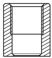
Standard welding adapter G1/2 hygiene:
Standard welding adapters enable the installation of sensors with G1/2 hygienic fitting in tanks or pipes under standard conditions.
①
②

③
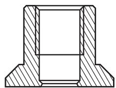
Fig. 1: Cut-away view
1: Welding adapter E43300
2: Welding adapter E43301
3: Welding adapter E30056

Welding adapters with collar, for example E43301, are suitable for a welded connection with an equally dimensioned extension on T-pieces ➕ Data sheet and Preparation welding adapter and wall ➕ 10
Special welding adapter G1/2 hygiene:
Special welding adapters enable the installation of sensors with G1/2 hygienic fitting in tanks under unfavourable or difficult welding conditions or circumstances. Thanks to their special flexible structure, they prevent distortion of the adapter and ultimately of the sealing edge to the sensor in the event of high heat input on the tank and adapter.
①

②

③

Fig. 2: Cut-away view
1: Special welding adapter E43918
2: Special welding adapter E43919
3: Special welding adapter E43920
4.1 Selection guide welding adapter
Selection guide wall thickness and welding adapter:
| Wall thickness | Recommendation |
| Thin (≤ 4 mm) | Standard and special welding adapter |
| Thick (> 6 mm) | Special welding adapter |
Installation positions special welding adapter:
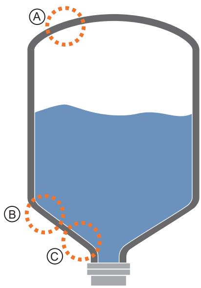
Fig. 3: Installation positions: Schematic illustration of a tank
Position A:
E43919 special welding adapter (D85 / rim height 6 mm) for installation in the tank head and in walls.

Fig. 4: Installation positions: Special welding adapter with built-in level sensor.
1: Note limited drainage on the inside.
2: Transition range of the adapter: do not reduce wall thickness!
Position B and C:
E43918 special welding adapter (D85 / rim height 6 mm) for installation in the tank bottom or in walls and larger tank diameters.
E43920 special welding adapter (D85 / rim height 12 mm) for installation in tank cones and thick walls and small tank diameters or tight radii.

Fig. 5: Installation positions: Special welding adapter with built-in level sensor.
1: Note limited drainage on the outside.
2: Transition range of the adapter: do not reduce wall thickness!
4.2 Basic notes
If the tank or the pipes are treated after the welding process (for example, grinding, pickling, sand-blasting, glass bead blasting, e-polishing or applying procedures such as powder coating, painting etc.):
▶ Make sure that the inside and sealing area of the adapter are clean and not damaged.
▶ Exclude a reduction in the wall thickness of the special welding adapter in the transition area.
Carry out a leak check after the welding process. Leak check with test adapter E43922 ➕ 17
The welding operation must be carried out by authorised personnel. The welding operation must be carried out carefully and according to state-of-the-art technology.
During welding and the following cooling phase the sensor must not be in place.
A welding mandrel or cooling adapter must be used during welding. Cooling ➞ 11
The surfaces must be free from any contamination.
Welding materials must be suitable for the adapter and wall material.
▶ The requirements in the specifications, of common practice, in regulations, norms, of intended use and the application must be applied.
▷ They determine the welding procedure, the welding material, the connection category and connection type, including chamfer, welding penetration depth and demands on the surface.
When used in hygienic areas to EHEDG and 3-A:
▶ Adhere to the applicable EHEDG and 3-A directives.
▶ Assure EHEDG-compliant or 3-A-compliant integration of the adapter in the plant (observe the respective notes in the operating instructions of the sensor to be used).
▶ 3-A approval: Use only adapters with 3-A approval and marked with the 3-A symbol.
Use in hygienic areas to EHEDG:
The food contact surface must be smooth (surface roughness Ra < 0.8 µ m) and the welding has to be done according to EHEDG guidelines 9 and 35.
▶ Use self-draining installation.
▶ For any structures in a tank, direct water jet cleaning must be possible.
Adapter with collar:

Fig. 6: Welding adapter E43301
Di: Diameter internal
Da: Diameter external
Use on a T-piece:
The welding adapter with collar is suitable for a welded connection with an equally dimensioned pull-out on T-pieces (→ data sheet).

The internal diameter of the main line DH must be at least the internal diameter Di of the welding adapter.
The internal diameter DH can also be larger if the pull-out remains the same size as the welding adapter.
Due to the transition to the sealing edge, the adapter is very easily accessible for cleaning despite the small recess to the inner wall of the pipe in the T-piece.
The distance between the surface (1) of the sensor and the inner wall of the main pipe should not exceed the diameter (2) of the pull-out in order to ensure cleaning in accordance with the applicable hygiene principles.
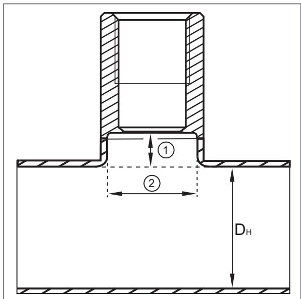
Fig. 7: Welding adapter E43301 on a T-piece
1: Distance between sensor and inner wall of main pipe
2: Inner diameter of pull-out T-piece
DH : Inner diameter of the main pipe
5 Installation

Observe and adhere to state-of-the-art technology and applicable regulations during the welding process.

Carefully read and apply the operating instructions of all components used.

ATTENTION
Danger to the plant and the environment during welding operations and rework.
▶ Consider potential dangers and adhere to applicable regulations and guidelines.

CAUTION
During the welding operation, the adapter, the surrounding material and any welding aid used can increase in temperature to over 65\ °C ( 149\ °F ).
▷ Risk of burns.
▶ Allow all components to cool down.

WARNING
Dangers to persons during welding operations, rework and pressure tests.
▶ Consider potential dangers and adhere to applicable regulations and guidelines.
5.1 Preparation welding adapter and wall

Be careful when working on the adapter.
▶ Exclude any damage to the sealing contour on the adapter.
▶ Do not remove any material from the transition area of the special welding adapters.

These specifications are only recommendations in the event that no specifications and / or welding instructions from welding engineers are available.
▶ Depending on the welding applications, chamfers are to be applied to the sheet and / or the welding adapter if required.
▶ Provide a drill hole / cut-out in the pipe or wall. The diameter of the drill hole / cut-out is determined by the intended welding strategy.
▶ Residual stresses in the sheet metal, e.g. in the cone or the dished end, resulting from the manufacturing process should, if possible, be released by pre-annealing so that no forces are transmitted to the adapter during the welding process.
5.2 Alignment of adapter / leakage port
Align the marking 1 (marking may vary) of the adapter to the position provided for the display (if any) or the cable entry of the screwed-in sensor.

Adapter with leakage ports according to EHEDG and 3-A:

For reliable self-emptying with an adapter with multiple leakage ports:
▶ Align one of the leakage ports so that it is located at the lowest possible point.

For reliable self-emptying with an adapter with a leakage port:
▶ Align the leakage port so that it is located at the lowest possible point.

Also applies to sensors with PEEK tip or PEEK seal on delivery: ➕ Operating instructions of the sensor.
If the PEEK seal is removed to seal against a metal surface (→ Operating instructions of the sensor), the sensor continues to rotate by approx. 90° until the end stop has been reached. In this case, the second mark (represented as a dot) provided for this purpose is decisive for alignment.
5.3 Cooling
During the welding process, depending on the welding method, higher amounts of energy are introduced into the centrally located adapter in the area of the weld seam; the adapter can dissipate this energy only to a limited extent into a welding aid which may be used.
To avoid overheating of the adapter:
▶ Ensure sufficient cooling times.
▶ Any specifications of a responsible welding specialist on targeted cooling devices must be applied.
▶ To cool the welding adapter, you can use a construction of your own or the E43929 cooling adapter (→ Accessories).
5.3.1 Cooling adapter E43929
The cooling adapter for G1/2 welding adapters absorbs the heat energy during the welding process via the flowing coolant and dissipates it, thus optimising dimensional accuracy.

The coolant must not cool the adaptor to such an extent that condensation forms at the welding point, e.g. when welding is interrupted.
▷ The quality of the welded joint will otherwise be significantly impaired.

The coolant must not overheat during the welding process. The medium must be available and circulating in sufficient quantities at the start of the welding process.

The coolant must not get into the area of the weld seam. ▷ The quality of the welded joint will otherwise be significantly impaired.
▶ Further information on the cooling adapter E43929 ➕ Operating instructions.
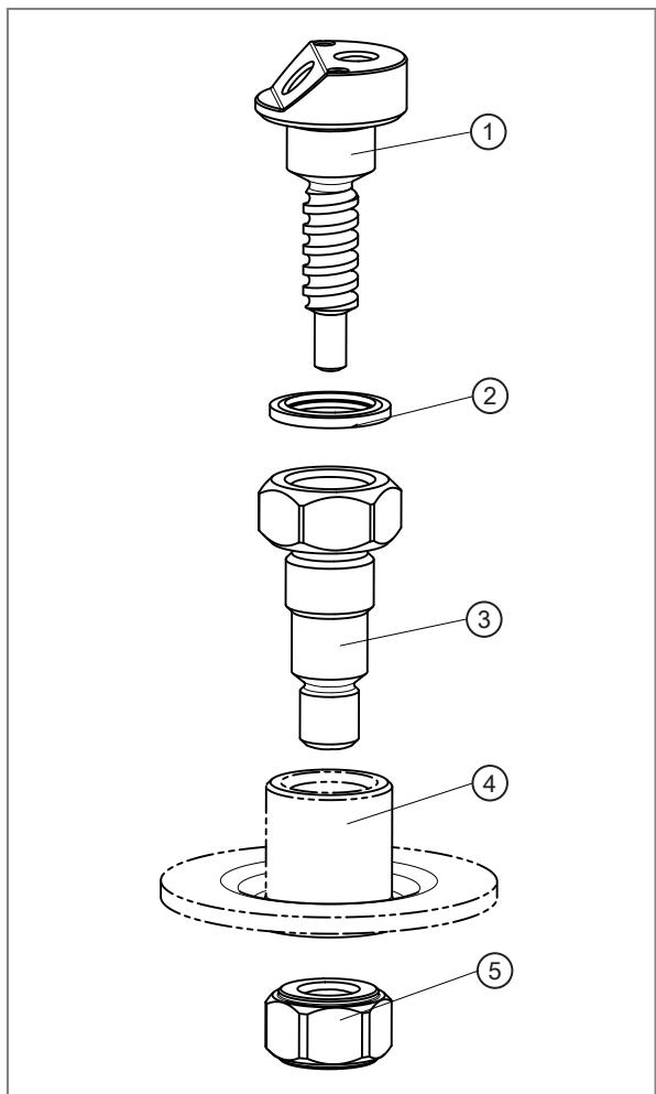
Fig. 8: Cooling adapter with optional welding adapter.
1: Internal water cooling
2: Seal
3: External water cooling
4: Optional welding adapter (not included)
5: Nut

Fig. 9: Cooling adapter (connections, flexible hose lines not included).
6: Internal thread G 1/8 for flexible hose connections
5.3.2 Welding process with cooling adapter E43929
▶ Screw the cooling adapter into the welding adapter (4).
▶ For tank applications, fit the locknut (5).
▶ Insert the welding adapter (4) into the prepared drill hole and attach it.
▶ Supply forming gas.
▶ Attach the connections and hoses to the internal threads (6) of the cooling mandrel (1).
▶ Activate cooling.
▶ Carry out the welding process.
▶ After each welding, including the cooling phase, check the thread of the welding adapter for ease of movement. To do this, loosen the cooling mandrel briefly after loosening the nut and then tighten it again.
▶ After completion, remove all components from the welding adapter.
5.4 Welding process in general

The basic notes and guidelines must be adhered to:
▶ The welding method must be suitable for the welding task and the power of the welding equipment must be adapted to the material thickness.
▶ During welding, avoid overheating of the adapter and observe sufficient cooling phases.
▶ Any specifications of a responsible welding specialist on targeted cooling devices must be applied.
▶ The sealing area of the adapter must not be damaged by weld spatter or similar. The sealing area should be sufficiently protected before starting the welding process.
▶ Use the welding mandrel E43314 or the cooling adapter E43329 Cooling ➕ 11 to dissipate heat, stabilise and protect the sealing area.
▶ Insert the welding adapter into the prepared drill hole and attach it.
▶ For an optimum welding result, apply a sufficient number of fixing points crosswise, if necessary.

▶ For an optimum welding result, apply the welding segments crosswise in the back-step method, if necessary.
▶ Ensure sufficient intervals between the individual sections to avoid overheating of the adapter.

▶ After each welding, including the cooling phase, check the thread of the welding adapter for ease of movement. To do this, loosen the welding aid / welding mandrel and tighten it again. If a locknut is used, loosen it first and then tighten it again.
▶ After completion, remove all components from the welding adapter.
▶ Remove any residue from the thread of the adapter without damaging the sealing edge.
▶ Screw in the sensor by hand in order to check for functionality of the thread. If the tightening torque is too high during screwing in, do not use any tools, but check the thread and replace the adapter, if necessary.

Carry out a leak check after the welding process. Leak check with test adapter E43922 ➕ 17
5.5 Processing the weld seam

If surface post-processing (e.g. grinding / polishing of the weld) is necessary, damage to the sealing edge for the sensor seal on the welding adapter and the material in the transition area on the special welding adapter must be avoided.
▶ Insert the device to protect the sealing edge (→ Table welding adapters).
- ▶ Carefully remove the material around the adapter in case of post-processing (e.g. grinding / polishing).
| Welding adapter | Grinding protection |
| Standard welding adapter, e.g. E43300 | Special grinding protection is not available. The sealing plug E43308 or the welding mandrel (E43314) can be used to protect the process connection. |
| Special welding adapter E43918 | E43923 Installation of E43923 on the special welding adapter E43918 ➕ 15 |
| Special welding adapter E43919 | E43924 Installation of E43924 on the special welding adapter E43919 ➕ 15 |
| Special welding adapter E43920 | E43923 Installation of E43923 on the special welding adapter E43920 ➕ 16 |

Use protective devices and equipment according to the product specifications, installation conditions and ambient conditions.

Read and apply the operating instructions and safety instructions for the tools used.
5.5.1 Processing special welding adapter

When processing the weld seam:
▶ Fit the grinding protection set to the special welding adapter.

Do not damage the sealing edge for the sensor seal and the material in the transition area on the special welding adapter.

The grinding protection must be centred on both sides before final tightening. Do not scratch the surfaces with the grinding protection caps.
5.5.1.1 Installation of E43923 on the special welding adapter E43918
▶ Install the grinding protection E43923 on the welded adapter E43918.

1: High hemisphere D = 70
2: M12 nut
3: M12 screw
4: Protective cable entry
5: Welding adapter E43918
6: Flat half shell D = 70
5.5.1.2 Installation of E43924 on the special welding adapter E43919
▶ Install the grinding protection E43924 on the welded adapter E43919.

1: High hemisphere D = 70
2: M12 nut
3: M12 screw
4: Protective cable entry
5: Welding adapter E43919
6: Flat half shell D = 70
5.5.1.3 Installation of E43923 on the special welding adapter E43920
▶ Install the grinding protection E43923 on the welded adapter E43920.

1: High hemisphere D = 70
2: M12 nut
3: M12 screw
4: Protective cable entry
5: Welding adapter E43920
6: Flat half shell D = 70
5.5.1.4 Processing of the weld seam for special welding adapters

Observe and use protective devices and equipment according to the product specifications, installation conditions and ambient conditions.

Observe and use the operating instructions and safety instructions for the tools used.

Do not remove any material from the special welding adapter in the transition area.
▶ Guide the grinding tool parallel to the surface to be processed.
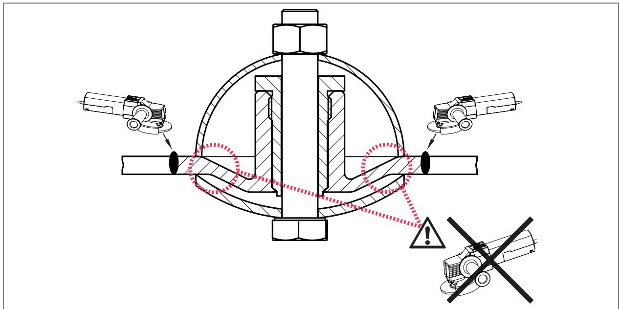
Fig. 10: Schematic illustration, components may vary.
5.6 Leak check

WARNING
Dangers during pressure checks.
▶ Consider possible dangers for persons and adhere to applicable regulations and guidelines.
5.6.1 Leak check with test adapter E43922

There must be a leakage port on the welding adapter for this leak check.
With the test adapter E43922, liquid or air is pressed via a pneumatic connection into the rear area of the welded adapter to determine whether liquid or air is leaking through the leakage port of the adapter, which means that the sealing point is leaking due to damage.
▶ Install the components of accessory E43922 on the welding adapter to be tested according to the illustration.
▶ For multiple use: Replace the PEEK sealing ring (3) if damaged ➕ Accessories E30459.
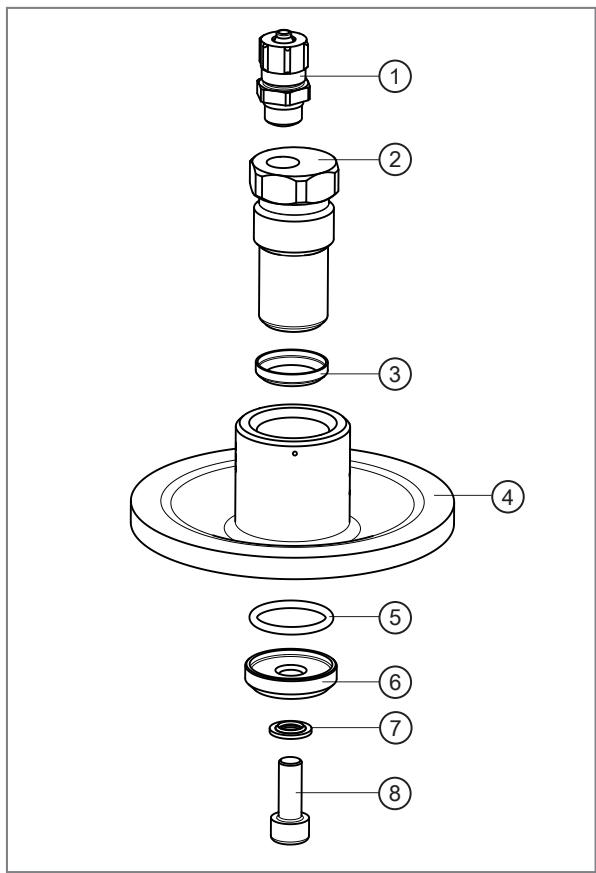
▶ Carry out the leak check.
1: Pneumatic connection
2: Test adapter G1/2
3: PEEK sealing ring
4: G1/2 hygienic welding adapter with leakage port (design varies)
5: O-ring FKM 18 x 2
6: Seal G1/2
7: Steel sealing ring / NBR M6
8: M16 x 16 screw

Fig. 11: E43922 installed in a special welding adapter
▶ If medium leaks during the check.
▷ Replace the welding adapter.
1: Air supply via pneumatic connection
2: Air outlet via the leakage port in case of a fault
5.6.2 Leak check of complete system

If a leak check of the complete system is to be carried out or the tank / system is only accessible from the outside and the accessory E43922 cannot be used.
▶ Insert the sensor (note the overload resistance of the sensor: ➕ Technical data www.ifm.com)
▶ No foreign plugs of any kind may be inserted.
▶ The sealing edge of the welding adapter must not be damaged.
▶ Do not use any additional sealing material.
▶ Only tighten the sensor with the torques approved for the welding adapter. ➕ Technical data www.ifm.com
▶ Carry out the leak check.
6 Install the sensor with G1/2 hygienic fitting

For installing a sensor or clamp fitting, a lubricating paste is needed. It must be suitable and approved for the given application and compatible with the elastomers used (e.g. seal).
▶ Observe the notes on installation in the operating instructions of the corresponding sensor.
▶ Installation must be carried out by qualified staff.
▶ Ensure the cleanliness of the sealing areas.
▶ Remove the protective packaging only just before mounting.
▶ If the sealing areas are damaged: Replace the adapter.
▶ For sensors with metal sealing edge: If the welding adapter is slightly warped or the sealing surface slightly damaged, the PEEK sealing ring E43323 (Accessories) can be used (Operating instructions LMTxxx).

The supplied O-ring (black) is only needed for specific LMT types to seal the rear area. It must not be used with sensors that already have an integrated (rear) seal or if its use would impair the function of the front sealing point (process seal).

The rear seal does not serve as a process seal.
▶ For sensors with O-ring seal: Apply the front seal.
▶ Screw the device into the adapter until it is hand-tight.
▶ Avoid damage to the sealing areas / to the separate seals.

If the device can only be screwed into the thread with great resistance, do not force! Otherwise the device or the adapter can be damaged.
▶ Do not rework the thread. Remove the adapter and weld in a new adapter.

Too much torque may impair the seal.
▶ Tighten the device using a spanner.

Tightening torque: ➞ Operating instructions of the screwed device.
7 Set-up
▶ Before setting up the system: Check all components for ingress resistance.
Setting up the sensor: ➕ Operating instructions of the sensor.
8 Cleaning and maintenance when used in 3-A applications
▶ Check all seals and sealing areas for damage.
▷ Replace if damaged.
▶ Recommendation: Replace changeable seals before assembly.
▶ Check contact areas for dirt. Clean all components with a cleaning solution which is suitable for the application and the materials used.
▶ Use of a soft brush for cleaning all inner and outer surfaces.
▶ Do not damage seals and sealing areas during cleaning.
▶ Only use clean components when reassembling.
9 Disposal
▶ After use dispose of the product or components in an environmentally friendly way in accordance with the applicable national regulations.


- 1 PRELIMINARY NOTE
- 1.1 SYMBOLS USED
- 1.2 WARNINGS
- 2 SAFETY INSTRUCTIONS
- 3 TRANSPORT, HANDLING AND STORAGE
- 4 INTENDED USE
- 4.1 SELECTION GUIDE WELDING ADAPTER
- 4.2 BASIC NOTES
- 5 INSTALLATION
- 5.1 PREPARATION WELDING ADAPTER AND WALL
- 5.2 ALIGNMENT OF ADAPTER / LEAKAGE PORT
- 5.3 COOLING
- 5.3.1 COOLING ADAPTER E43929
- 5.3.2 WELDING PROCESS WITH COOLING ADAPTER E43929
- 5.4 WELDING PROCESS IN GENERAL
- 5.5 PROCESSING THE WELD SEAM
- 5.5.1 PROCESSING SPECIAL WELDING ADAPTER
- 5.5.1.1 INSTALLATION OF E43923 ON THE SPECIAL WELDING ADAPTER E43918
- 5.5.1.2 INSTALLATION OF E43924 ON THE SPECIAL WELDING ADAPTER E43919
- 5.5.1.3 INSTALLATION OF E43923 ON THE SPECIAL WELDING ADAPTER E43920
- 5.5.1.4 PROCESSING OF THE WELD SEAM FOR SPECIAL WELDING ADAPTERS
- 5.6 LEAK CHECK
- 5.6.1 LEAK CHECK WITH TEST ADAPTER E43922
- 5.6.2 LEAK CHECK OF COMPLETE SYSTEM
- 6 INSTALL THE SENSOR WITH G1/2 HYGIENIC FITTING
- 7 SET-UP
- 8 CLEANING AND MAINTENANCE WHEN USED IN 3-A APPLICATIONS
- 9 DISPOSAL
Brand : IFM
Model : E43920
Category : Industrial sensor