
REF18FCBIPLV - Refrigerator BERTAZZONI - Free user manual and instructions
Find the device manual for free REF18FCBIPLV BERTAZZONI in PDF.

| Product Type | Built-in Refrigerator |
| Brand | Bertazzoni |
| Model | REF18FCBIPLV |
| Appliance Width | 17 3/4'' (451 mm) |
| Appliance Height | 84'' (2134 mm) |
| Appliance Depth | 25'' (635 mm) |
| Minimum Floor Load | 544 kg (1200 lbs) |
| Electrical Supply | 115 V, 60 Hz, 15 A, NEMA 5-15P plug |
| Water Connection | Yes (for ice maker and water dispenser, pressure 25-80 psi) |
| Climate Classes | SN, N, ST, T (10°C – 43°C) |
| Refrigerant | R600a (isobutane, flammable) |
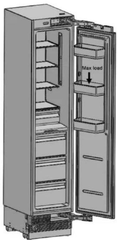
| Maximum Door Load | 22 lbs (10 kg) |
| Maximum Door Opening | 115° (with door panel thickness ≤ 38 mm) |
| Reversible Doors | Yes (reversal kit included) |
| Built-in Installation | Yes (requires a cabinet niche) |
| Anti-tip Brackets | Included (mandatory) |
| Ventilation Grille | Removable, not obstructable |
| Overlay Panels | Customizable (min. thickness 19 mm, max. weight 30 kg per door) |
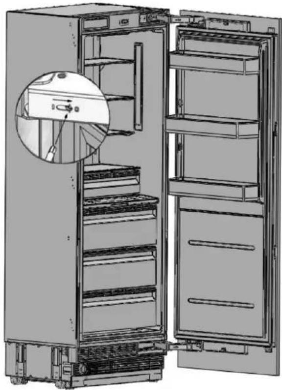
| Interior Lighting | Yes (check with power on) |
| Maintenance | Regularly clean the ventilation grille |
| Repairability | Detailed installation manual (182 pages), professional intervention recommended |
Frequently Asked Questions - REF18FCBIPLV BERTAZZONI
User questions about REF18FCBIPLV BERTAZZONI
0 question about this device. Answer the ones you know or ask your own.
Ask a new question about this device
Download the instructions for your Refrigerator in PDF format for free! Find your manual REF18FCBIPLV - BERTAZZONI and take your electronic device back in hand. On this page are published all the documents necessary for the use of your device. REF18FCBIPLV by BERTAZZONI.
USER MANUAL REF18FCBIPLV BERTAZZONI
1.1 Symbols and Their Meanings 5
1.2 Disposing of the packing materials 5
1.3 Climate class.. 6
1.4 Food Load Bearing Capacity of the Doors 6
2. BEFORE INSTALLATION 7
2.1 Installation location 7
2.2Cabinetry 8
2.3 Ventilation 8
2.4 Electrical Connection 8
2.5 Water Connection (where applicable) 8
2.6 Tool List 8
2.7 Alternatives for Installation 9
2.8 Preparation for Installation 9
2.9 Location of the Electrical Wiring 10
2.10 Location of the Water System 11
2.11 Product dimensions 12
2.12 Unpacking 17
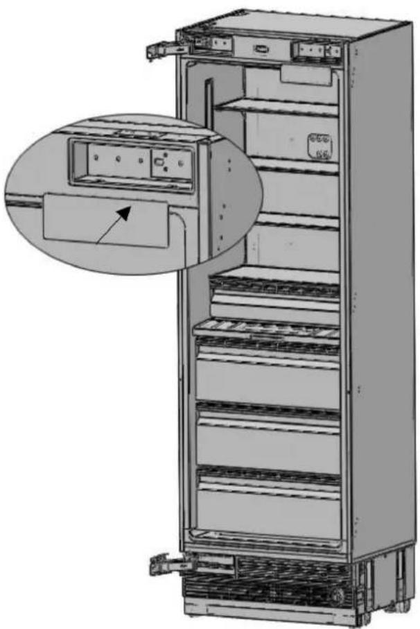
2.13 Removing the Connectors on the Side Wall of the Unit 18
2.14 Removing the Installation Hardware 19
2.15 Removing the vent hole assembly 20
3. INSTALLATION INSTRUCTIONS 21
3.1 Before Installation 21
3.2 Mounting the Anti-Tip Brackets 21
3.3 Preparing the Water Hose and the Electrical Connection 24
3.4 Installation in the cabinet 24
3.5 Overlay Panel Installation and Preparation 31
3.6 Hinge Adjustment and Reversing the Door Swing 43
1.1 Symbols and Their Meanings
Symbols used in the installation manual are as follows.

Note
Important information or useful tips for use

Warning
Conditions that may damage the product or affect its operation

Caution
Situations entailing a serious risk of injury
1.2 Disposing of the packing materials
The packing materials have been designed to protect the product during transport.
The packing materials used for the product are not harmful to the environment when disposed of and they need to be recycled.
All plastic packing materials, bags, etc. must be disposed of safely and kept out of the reach of children.
Please return the packing materials to your dealer.

WARNING:
This installation manual is intended to aid installation teams. The User Manual provided with the product must also be taken into account.
You may be seriously injured and your product damaged if you ignore the warnings provided in this manual. Please read the following carefully.

WARNING:
R600a Refrigerant
This product contains R600a isobutane refrigerant, which is a very eco-friendly natural gas. However, it is also flammable. Please heed the warnings below:
- If the product has been transported horizontally, you must wait for a minimum of 4 hours before plugging it in.
The following instructions must be
followed during installation:
- The dimensions of the installation area must be adequate.
- The dimensions, features and position of the object used to support and secure the product in said area must be suitable.
- Minimum clearances between product parts and surrounding structures must be adequate.
- Minimum dimensions and proper positioning of ventilation holes must be heeded.
- The product must be connected to a non-GFCI protected dedicated circuit, and there must be a suitable water line connection (for models with ice maker and water dispenser).
The product must be able to be disconnected from the power supply after installation. - The socket or fuse must be accessible, so as to be able to shut off power to the product.
- Extension cords and ungrounded (twoprong) adapters may not be used.

CAUTION:
You must wear protective gloves and eye protection when installing the product.
You must also wear hearing protection when using a drill or similar tools.

CAUTION:
Make sure that the electrical circuit is suitable for the product.

CAUTION:
The product must be installed by a qualified technician according to the installation instructions.

WARNING:
The product may tip over, because it is quite heavy. Precautions must be taken to prevent this from occurring.
The product's doors must be kept closed until it reaches its destination; it must be transported in the manner described in the installation instructions.
1.3 Climate class
| Climate range Ambient temperature of the room | This appliance has been designed to be used in certain specific climates (ambient temperatures ranges). It must not be used outside of these ranges. | |
| SN (Extended temperate) | Between +50°F (10°C) and +90°F (32°C) | |
| N (Temperate) Between +60°F (16°C) and +90°F (32°C) | ||
| ST (Subtropical) Between +60°F (16°C) and +100°F (38°C) | ||
| T (Tropical) Between +60°F (16°C) and +110°F (43°C) | ||
1.4 Food Load Bearing Capacity of the Doors
| Category | REF18FCBIPRV / REF18FCBIPLV | REF24FCBIPNV REF2 | 4RCBPNV REF30RCBPNV | |
| Max. load 22lbs (10kg) 3 | 3 lbs (15kg) 33lbs (15kg) | 55lbs (20kg) |

2.1 Installation location
You must follow the instructions below:
The floor on which the product is to be installed must be capable of bearing 1,200 pounds (544kg) minimum.
The kitchen floor and the bottom of the product must be equally level. Otherwise, problems may occur with the appliance's air flow.
There must be no obstructions at the rear and on the side walls of the product's installation location that would prevent its installation.
The electrical outlet must be in the correct place.
The dimensions of the cabinet where the appliance is to be installed must be in strict conformity with the dimensions provided in the manual.
Do not install the appliance adjacent to another fridge/freezer. Otherwise, condensation and damage may occur. (Please see "Dual-Fridge Cabinet Installation" for detailed information).
The level of the floor where the product is to be installed must be checked with a bubble level.
The installation location must not be exposed to direct sunlight and must be away from heat sources (ovens, radiators, etc.).
The ambient temperature must be between 50^ (10^) and 110^ (43^) . Otherwise, malfunctions may occur when the appliance is running.
> If it is not possible to avoid installing the product near a heat source, the minimum clearances provided below must be maintained between the appliance and the given source:
- 1 1/4'' (32 mm) from electric ranges or ovens
- 12" (305 mm) from gas or fuel-powered kitchen ranges or ovens
Please heed the following rules:
The electrical outlet or panel must be easily accessible in case of an emergency; it must not be hidden behind the product.
Neither the plug nor the cable may touch the back surface of the appliance. Otherwise, it may be damaged by the appliance's vibrations.
Do not connect other equipment plugs behind this appliance.
If the humidity level is high where the appliance is being used, its exterior surfaces may become corroded.
To prevent corrosion, keep the installation room dry and well-cleaned.
To prevent the risk of electric shock:
Connect the plug to a grounded 3-prong outlet.
Do not remove plug's grounding prong.
Do not use adapters.
Do not use extension cords.

CAUTION:
Failure to follow these instructions may result in fire, electric shock or death. Connecting the appliance's grounding conductor in the wrong place may lead to electric shock. Please have the grounding checked by a qualified electrician or service technician if you have any doubt about the proper grounding of the appliance.
Installation, repairs and other procedures performed by unqualified persons may give rise to hazards. Before installing the appliance, make sure that the voltage, load and circuit current parameters on the data plate are in compliance with the power supply in your house.
The appliance is provided with a NEMA 5-15 P plug and a 3-prong power cord which is in the UL list and ready to be connected to a 115V,60Hz power supply. Fuse is 15 A. The appliance must be connected to a 3-prong socket. The plug must be installed only by a licensed electrician.
If the electrical wiring or the electric power supply of the house requires alteration, the necessary procedures must be performed by a qualified electrician.

CAUTION:
Do not install your refrigerator:
- in an outdoor space,
- in a location with dripping water,
- in a location where the temperature is lower than 50^ (10^)
2.2Cabinetry
Make sure that the cabinetry inside which you will install the appliance has been securely mounted in your kitchen.
Your cabinet must be properly secured to the floor and to the wall using appropriate mounting hardware.
For the best installation, clearances between the cabinet and the appliance must be in compliance with the measurements specified in the installation instructions.
The side walls must be free of obstructions and their surfaces must be flat. The minimum thickness of the side walls must be 5/8'' (16 mm).
The minimum thickness of the door panels to be attached to the appliance must be 34 (19 mm).

CAUTION:
There is a stainless steel door and stainless kickplate option. Please consult your Authorized Service Provider.
2.3 Ventilation
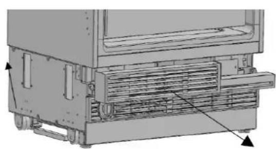
Ventilation openings where the air enters and exits the unit must never be obstructed. The user is responsible for periodically cleaning off the dust and debris that can accumulate on the grill over time.
2.4 Electrical Connection
Never use an extension cord.
The electrical outlet must be grounded and checked by an authorized technician.
The positioning of the electrical wiring must comply with the measurements specified in the manual.

CAUTION: RISK OF ELECTRIC SHOCK
Electrical grounding is necessary. This appliance is equipped with a three-prong plug to protect you against possible electric shocks.
- Do not remove the round grounding prong from the plug.
-
Do not use two-prong grounding adapters.
-
Do not use an extension cord to supply power to the product.

CAUTION:
Do not connect the grounding cable to the gas line. Please have the grounding checked by a qualified electrician if you are not sure about the grounding of the appliance. Do not install a fuse on the neutral line or on the grounding circuit.

WARNING:
Please wait for 3-6 hour before connecting the appliance to the power supply, in order to protect it against possible damage. This will allow the balance of the refrigerant and the lubricants in the system to be restored.
2.5 Water Connection (where applicable)
Water supply pressure must be within the range specified in the manual.
The location of the water line connection must comply with the area measurements specified in the manual.

Note:
A bypass plug is recommended for the water filtering system if a reverse osmosis system is used.
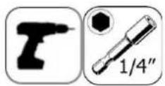
2.6 Tool List
The tools to be used when installing the product are as follows:

Cordless drill

Safety goggles
1 / 2 "wrench

Hammer

Ladder

2.4 drill bit
0 8.0 drill bit
Box cutter

Safety gloves

Tape measure

Phillips-head bit

14" hex bit

Bubble level

Appliance dolly

Tape
2.7 Alternatives for Installation
The appliance can be installed in a variety of ways depending on the kitchen design. It must be installed in a location where it is certain that the door can be opened and closed properly. If the doors cannot open up to at least 90 degrees the appliance drawers will not be able to be opened.
- Single-fridge cabinet placement methods
- Dual-fridge cabinet placement methods
2.8 Preparation for Installation
The instructions below refer to a built-in installation.
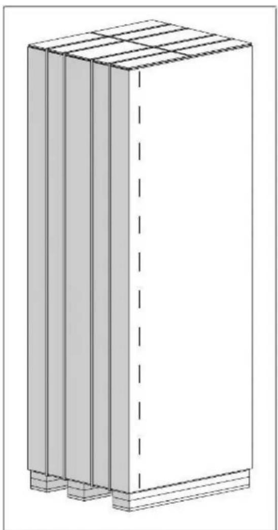
In a built-in installation, the appliance is installed in a cabinet niche or framed in with panels.
Niche Dimensions
- The niche dimensions below must be checked before beginning the installation.
2. BEFORE INSTALLATION
| Category | REF18FCBIPRV / REF18FCBIPLV | REF24FCBIPNV REF24RCBPNV REF30RCBPNV | ||
| A width | 18" (457mm) | 24" (609mm) 24" (609mm) | 30" (762mm) | |
| B depth | 25" (635 mm) | 25" (635 mm) 25" (635 mm) | 25" (635 mm) | |
| C height | 84" (2134 mm) | 84" (2134 mm) 84" (2134 mm) | 34 mm) 84" (2134 mm) | |

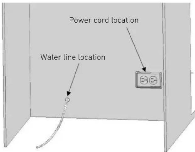
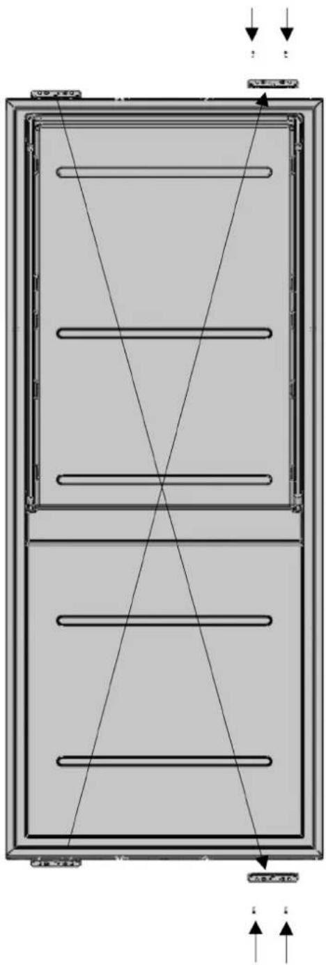
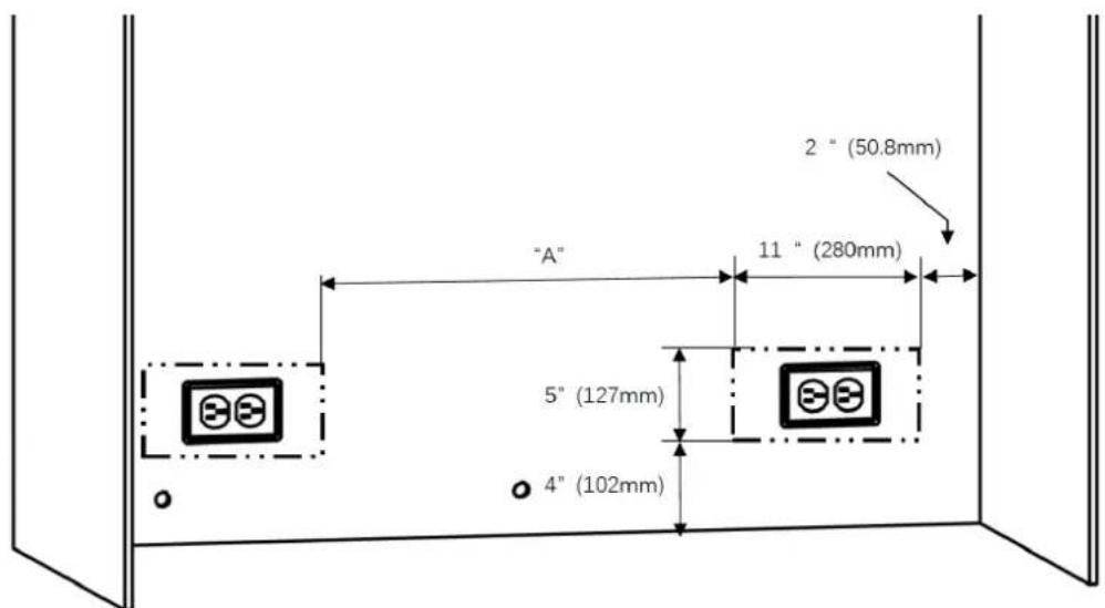
2.9 Location of the Electrical Wiring
The location of the electrical outlet in the cabinet where the product is to be installed must be within the area shown in the figure.

CAUTION:
Do not use extension cords or two-prong adapters and do not remove the ground terminal of the grounding cable.

CAUTION:
A qualified electrician must ensure that the poles of the socket are connected correctly. Verify that the grounding of the socket is correct.
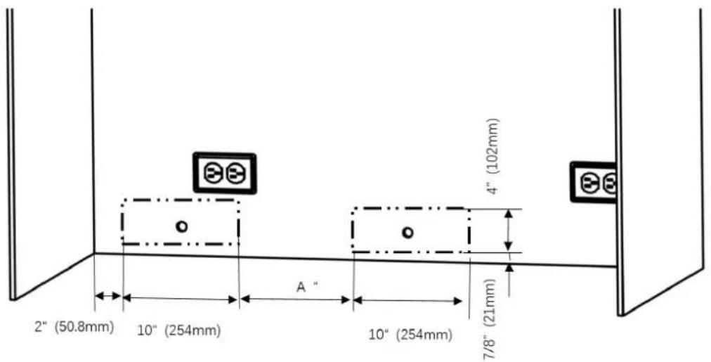
2.10 Location of the Water System
The water connected to the water supply must be potable.
The location of the water line connection must be within the area shown in the figure below.
The refrigerator's water system must be connected to the house's main water supply.
The user must be able to switch it on/off using the valve when necessary.
Objects that might pierce the water hoses or cause them to twist must not be present where the water line is installed.
The pressure of the water system must be between 25-80 psi (1.7-5.5 Bar).
If the water pressure exceeds 80 psi, install a pressure limiting device or water impact protector to the inlet valve. Do not install or operate the appliance if it is possible for the water pressure to exceed 120 psi.

WARNING:
Make sure that there is no water leakage when establishing the water connections.
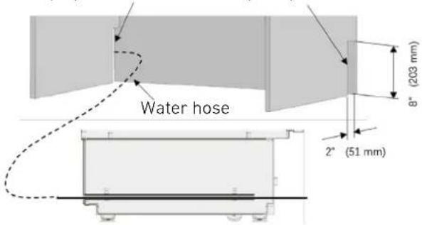
Otherwise, water may damage the cabinetry. The water supply line must located in the cabinet where the appliance is to be installed. The user must be able to switch it on/off using the valve when necessary. You will need a hose with a minimum length of 60'' (1.5 meters) and a diameter of 14 for the appliance's water connections during installation. A connector that has a thread with an external diameter of 14 must be used to connect the end of the hose to the product.
Before completing the installation, makesure that water flows and that there is no water leakage.

WARNING:
- The level of the floor where the product is to be installed must be checked with a bubble level.
- The cabinet flanges must be checked with a bubble level to ensure that they are perfectly vertical.
- If the appliance is not perfectly level and vertical, problems may arise with the installation.
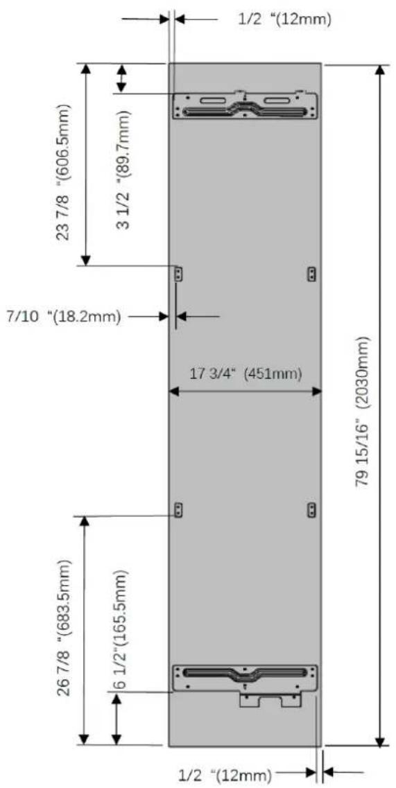
2.11 Product dimensions
| Category | REF18FCBIPRV / REF18FCBIPLV | REF24FCBIPNV REF24RCBPNV REF30RCBPNV | |
| A 17 3/4" (45 mm) 23 3/4" (603mm) 23 | 3/4" (603mm) 29 3/4" (756mm) |
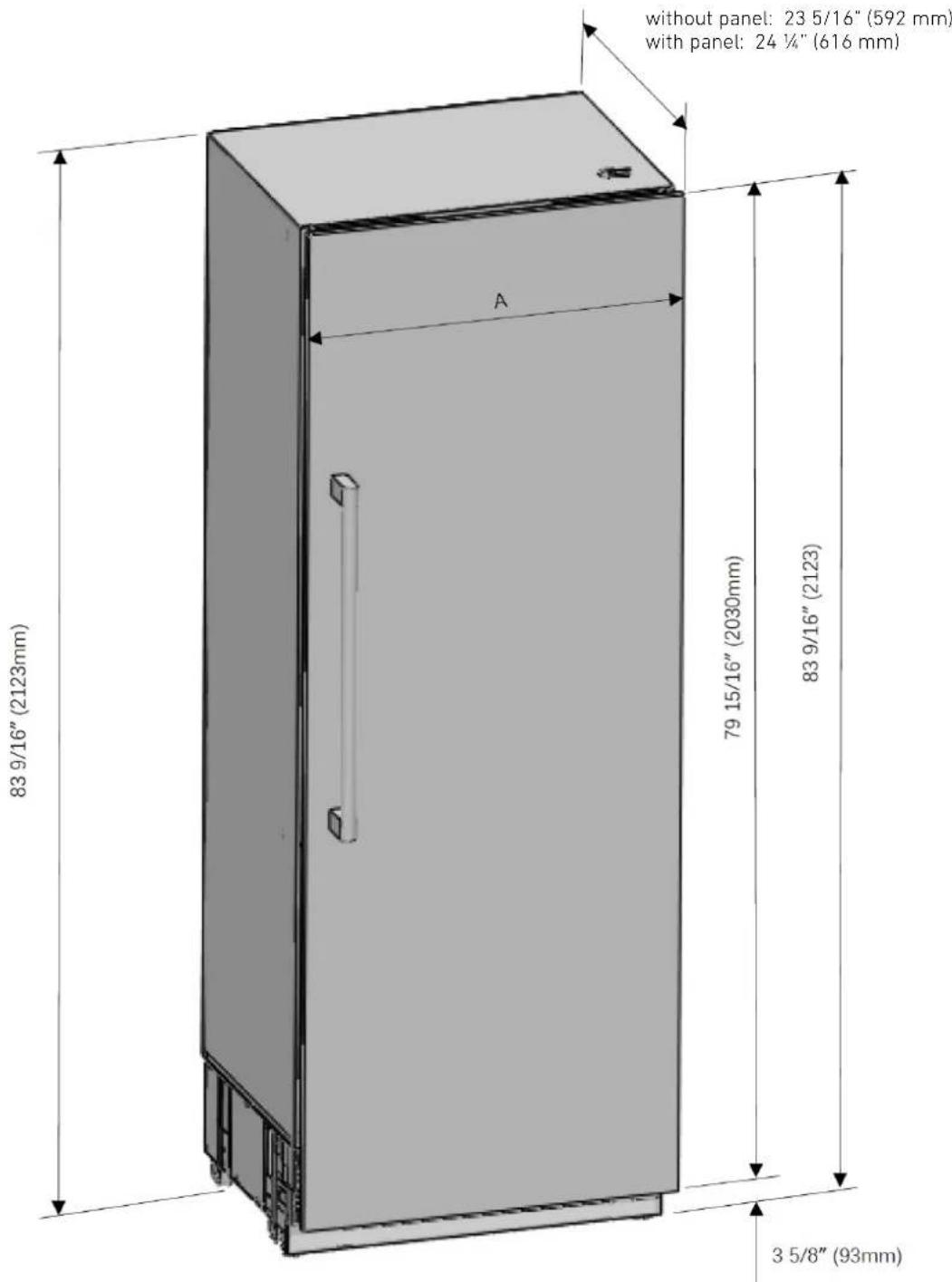
EN
| Category | REF18FCBIPRV / REF18FCBIPLV | REF24FCBIPNV REF2 | 4RCBPNV REF30RCBPNV | |
| A 20" (508) 26" (660) 26" (660) 32" (813) | ||||
| B 4 3/8" (110) 4 3/8" (110) 4 3/8" (110) 4 3/8" (110) | ||||
| C 11" (280) 14" (356) 14" (356) 16" (406) |
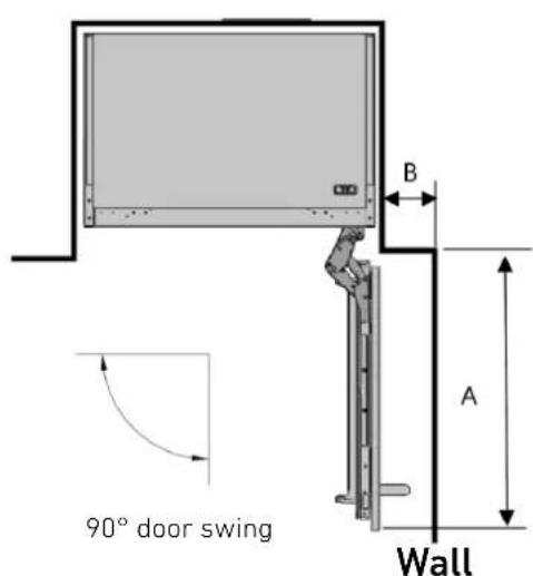
A:Door depth (90^)
B: Minimum door clearance to adjacent wall ( 90^ - reduced internal access)
C: Minimum door clearance to adjacent wall ( 115^ - full internal access)

Anti-tip bracket location

Minimum height adjustment for leveling
1 5 / 8'' (42mm)
EN

Based on the cabinet cutout height, the kitchen toe kick can be installed with following heights:
| A | B | |
| standard 4" (101mm) | 84" (2134mm) | |
| minimum 3 3/4"(96mm) | 83 13/16" (2129mm) | |
| maximum 5 3/8" (136mm) | 85 3/8" (2169mm) |

| Category | REF18FCBIPRV / REF18FCBIPLV | REF24FCBIPNV REF2 | 4RCBPNV REF30RCBPNV | |
| C 18" (457mm) | 24" (609mm) | 24" (609mm) | 30" (762mm) | |
| D 17 3/4" (45 mm) | 23 3/4" (603mm) | 23 3/4" (603mm) | 29 3/4" (75 6mm) |
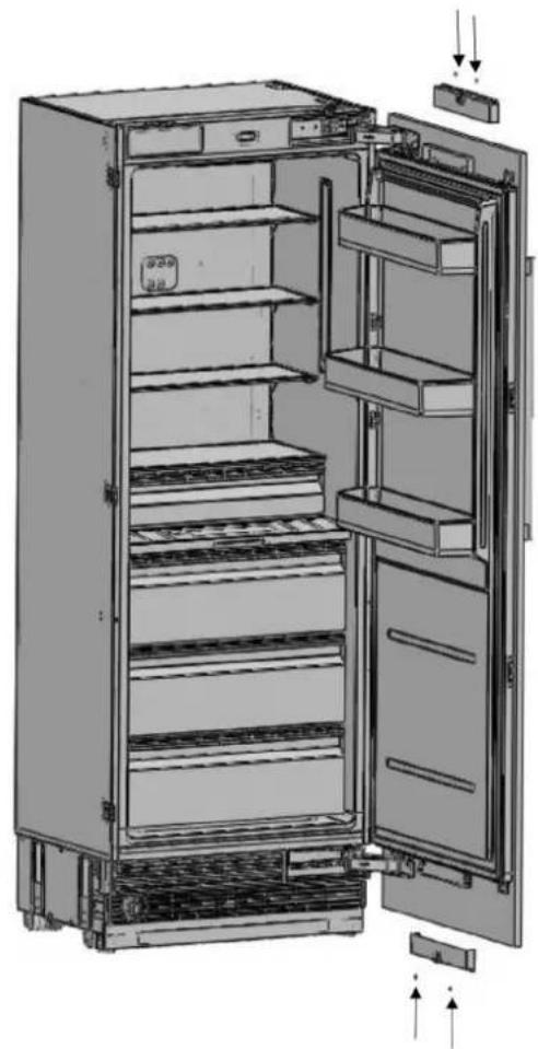
2.12 Unpacking

WARNING:
At least two people must carry the refrigerator.

- Use a box cutter to remove the tape.
- Cut the cardboard packaging along the dotted lines using a box cutter and remove it.
- Remove the polystyrene packing material.

CAUTION:
Do not remove the tape from the upper door of the appliance until the refrigerator is placed in the cabinet.
Tipping risk.
2.13 Removing the Connectors on the Side Wall of the Unit
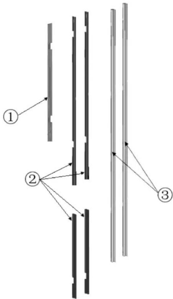
| No. Part name Specs 18 24 30 | |||||
| 1 Trim | furniture top | PVC extrusion L=457 1 | |||
| PVC extrusion L=609 1 | |||||
| PVC extrusion L=762 1 | |||||
| 2 Trim | furniture side | PVC extrusion L=1,259 2 2 2 | |||
| PVC extrusion L=617 2 2 2 | |||||
| 3 Trim | door side PVC extrusion L=1,78 | 1 2 2 2 | |||
Conference
| Category | REF18FCBIPRV / REF18FCBIPLV | REF24FCBIPNV REF2 | 4RCBPNV REF30RCBPNV | |
| Abbreviation | 18 | 24 | 24 | 30 |
2.14 Removing the Installation Hardware
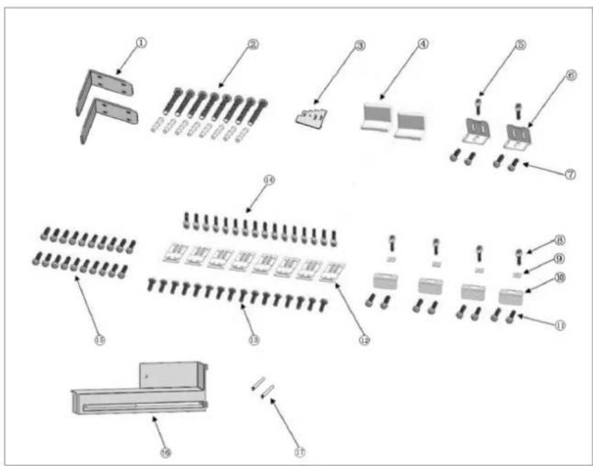
| No | Part name Spec 18 24 30 Remark | |||||
| 1 | Anti-tip bracket T4.0, | Cr+zn-coating | 8 8 8 | |||
| 2 | Anti tip bracket screws and dowels | M8*L60 | 8 8 8 | |||
| 3 | Position adjustment jig | PS | 1 1 1 | |||
| 4 | Cover furniture door bracket abs | - | 2 | 2 | ||
| 5 | Truss washer head | M4*12 | - | 2 | 2 | |
| 6 | Bracket furniture door T1.0, | Cr+zn-coating | - | 2 | 2 | |
| 7 | Counter sunk head screw ST4x14 | - | 4 | 4 | ||
| 8 | Truss washer head | M4*12 | 4 4 4 | |||
| 9 | Square washer T1.0, | Cr+zn-coating | 4 4 4 | |||
| 10 | Center mounting bracket T1.0, | Cr+zn-coating | 4 4 4 | |||
| 11 | Counter sunk head screw ST4x14 | 8 8 8 | ||||
| 12 | Bracket furniture T1.0, | Cr+zn-coating | 8 8 8 | |||
| 13 | Counter sunk head screw | STM4x14 16 16 | 16 | |||
| 14 | Truss washer head | M4*12 | 16 | 16 | 16 | |
| 15 | Counter sunk head screw | STM4x14 | 16 | 20 | 20 | Furniture door hanger bracket |
| 16 | Air vent hinge part | ABS | - | 1 | 1 | Door opening direction change |
| 17 | 90°limit pin | ∅4 | 2 2 2 | Door 90°opening use |
anti tip bracket screws dowels

Truss washer head screw
Spec: M4x12
Fixing Refrigerator
Such as cabinet and door (press part)

Counter sunk head screw
Spec: ST M4x14
Fixing the cabin and
furniture door
(wood part)
2.15 Removing the vent hole assembly
- Remove 5 screws to take out the Vent Hole Assembly.

EN
3.1 Before Installation
Proceed with installation of the product according to the instructions below. Be sure to take into account national and local code requirements regarding installations.
Please comply with the following:
For the USA, The National Electrical Code, ANSI/ NFPA 70 (latest version)/State or Municipal directives and/or regional directives.
- For Canada, The Canadian Electrical Code, C22.1 (latest version)/State or Municipal directives and/or regional directives.
3.2 Mounting the Anti-Tip Brackets

WARNING:
If the unit cannot be secured to the cabinetry (which in turn must be secured to wall) to prevent tipping, make sure to use the supplied anti-tip brackets in order to prevent the appliance from tipping over.

WARNING:
Make sure that there is no electrical or water connection in the adjacent cabinets into which the mounting screws will be screwed to secure the refrigerator.

WARNING:
Please remember to use the necessary protective equipment when drilling holes in the wall and performing the installation.
- Use a tape measure to mark the wall for installation of the anti-tip brackets.


| Category | REF18FCBIPRV / REF18FCBIPLV | REF24FCBIPNV REF24RCBPNV REF30RCBPNV | |
| A 18" (457mm) | 24" (609mm) | m) 30" (762mm) | |
| B 11 5/8" (295mm) | 17 5/8" (447mm) | 5/8" (447mm) | 23 5/8" (600mm) |
| C 3 3/16" (81mm) | 3 3/16" (81mm) | 6" (81mm) | 3 3/16" (81mm) |
- For the most secure installation, use a stud-finder to secure the anti-tip brackets in wall studs. If no studs are present at the correct installation location, follow the instructions below.

WARNING:
Always make sure that the area to be drilled into is free of any waterlines or electrical circuits, which could cause damage, injury, or death.
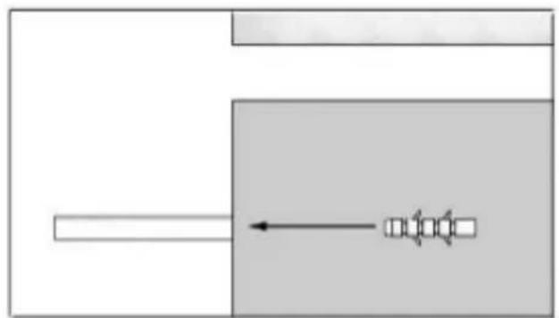
- Use a drill to create holes for wall anchors (#2) at the marked points. (5/16", 08)

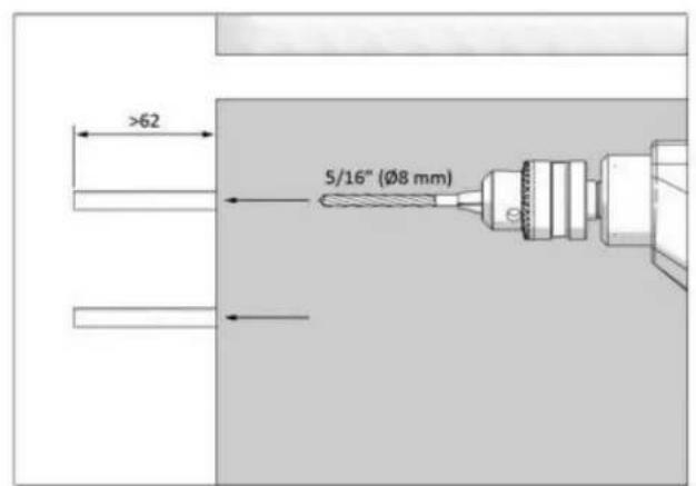
- Use a hammer to install the wall anchors (#2) if no stud is present.

- Install the brackets (#1) in place, using 4 screws for each.
You must use both (two) brackets to ensure that the appliance is safely supported.


NOTE:
If you are not confident that the supplied connectors and anti-tip brackets are mounted on the wall as securely as they should be, you can use alternative anti-tip methods.
If there is a cabinet panel behind the back wall of the refrigerator, make sure that it is securely fastened to the wall. For this, you need to be sure that the back wall of the cabinet panel is affixed to a wall stud.
EN
Alternative anti-tip method:
If the anti-tip brackets cannot be mounted securely, you must use the alternative method below. For this method, you can use wooden boards to avoid the risk of tipping over.
They must be installed as illustrated in the figure below.
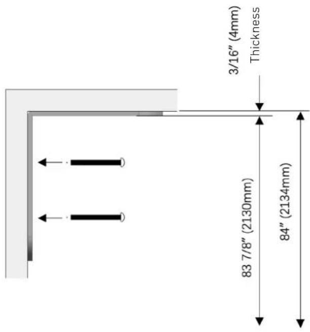
There must be no clearance between the appliance and the wooden support.
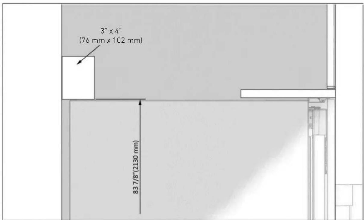
T minimum section dimensions of the wooden support must be 3'' × 4'' (76 mm x 102 mm). T width of the support must be equal to the clearance where it will be installed. This can be achieved using one 4'' × 4'' (102 mm x 102 mm) or two 2'' × 4'' (51 mm x 102 mm) pieces of framing lumber.
The calculation of blocking depth is based on a standard niche depth. If the depth of the niche is greater than 24^ (610 mm), ensure the blocking overlaps the upper rear fridge body by 2^ (51 mm).
Position the wooden support, mark the location on the rear wall, select suitable screws and mount it securely.

WARNING:
The quantity and type of screws or fasteners to be used for affixing wooden blocking must be suitable for ensuring a secure connection to the rear wall.
3.3 Preparing the Water Hose and the Electrical Connection
Inspect all water connections for leaks. Water leaks can cause significant damage over time. It is recommended to use a 1/4'' water line with a minimum length of 60'' (1.5 meters) with a threaded 1/4'' female connector end. Before finishing the installation, turn the water on to ensure that water is flowing and that there are no leaks.
A connector that has a thread with an external diameter of 14 must be used to connect the end of the hose to the product.
Allow for sufficient slack in the water supply line, providing a minimum of 10^ of length from the base of the unit once it is installed in the niche. This provides some allowance for connections and adjustments if needed.
The product must be connected to a 3-prong outlet on a dedicated 15 amp circuit; local electrical and building codes should be respected.
You can choose method A or method B below to prevent the power cord from getting wedged in.
Method A: Position the water hose and the power supply connections on the back.
Method B: Position the water hose and power supply connections on the side.
Keep open for water line Keep for power cord
3.4 Installation in the cabinet
Taking the Refrigerator from the Wooden Pallet
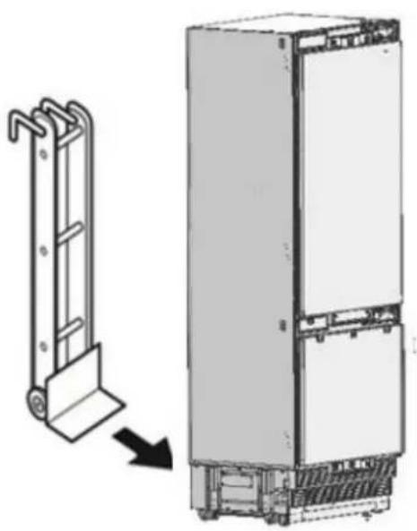
- Remove the brackets which secure the refrigerator to the wooden pallet as shown below.


- Slowly tilt the refrigerator back and remove it from the pallet, taking care not to damage the underside of the unit. When transporting the unit, always carry it from the sides to ensure that the unit's feet remain on the base of the appliance dolly.


NOTE:
Exercise extreme caution when handling the unit, as the underside of the fridge has components vital to its proper operation; damage to these components could result in a malfunction or potential leakage of condensate and damage to floors.

CAUTION:
The risk of tipping over is high from this point forward. You should not open the doors until the product is placed into the cabinet.
Placing the refrigerator into the cabinet niche.
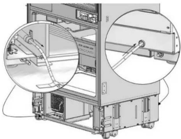
- Insert the water supply hose into the channel opening at the back of the unit and pull it through to the front of the unit to ensure that the water connection can be made once the unit is installed in the niche.

NOTE:
Use the method below to prevent the cord from getting wedged in.

Power cord
Connect the electrical plug to the power outlet. Turn on the unit to ensure it has power. (To see if the product is operating, check if the lamps in the freezer compartment are on or off).

NOTE:
Protect the front edges of the cabinet niche with masking tape; this will help protect them from damage when pushing the unit back into the niche. Use some packing tape to secure the excess electrical cord to the back of unit to prevent slack from catching under the unit during installation.

NOTE:
The unit's plug must be accessible after installation. If the plug is not accessible after installation, the power must have a dedicated circuit breaker which can be accessed to cut power off using the main switch.

WARNING:
Make sure that the power cord does not get wedged in when placing the product.
- Push the product carefully towards the cabinet to position it; the unit should slide into the niche with relative ease. If you experience resistance while placing the product in the cabinet:
- The floor might be uneven.
- The adjustable feet might be loose (please see the relevant section to learn how to adjust the adjustable feet).
- You must attach the freezer door temporarily to align the product before placing it.

NOTE:
Use the upper edges of the fridge and freezer doors to align the unit in the niche opening.
Adjustment of other edges is explained in the following pages.

Adjusting the height of the refrigerator within the niche
- Use the adjustable leg mechanism to raise, lower and level the unit in the niche as per the diagram below.


WARNING:
Once the unit is pushed into the niche, raise the front feet first; this will reduce the risk of the unit tipping forward during the height adjustment process.
The maximum height that the adjustable feet can reach is 19 / 16'' (40 mm).
EN
A/D -Turn the adjusting rod clockwise to lift the front B/C -Turn the adjusting rod clockwise to lift the rear

After adjusting the adjustable feet, check that the appliance is level both side-to-side and back-to-front by placing a level on the floor of the freezer compartment (the drawer should be removed for this).
Adjusting the refrigerator based on the cabinet niche.
- For products with supplied stainless steel panel doors, the position of the unit is adjusted so that the door and the cabinet surface are flush and a min. 1/8 distance from panels and gables is ensured.
- For panel-ready units, the refrigerator should be installed at a depth that takes into consideration the custom overlay panel thickness, so as to ensure a flush installation, if desired.

NOTE:
It is important to align the upper edge of the freezer drawer when aligning the unit, as its height and position are fixed. All of the other panels can be adjusted using the adjustment mechanisms built into the mounting hardware. As shown below, an installation depth template tool is provided for your convenience.

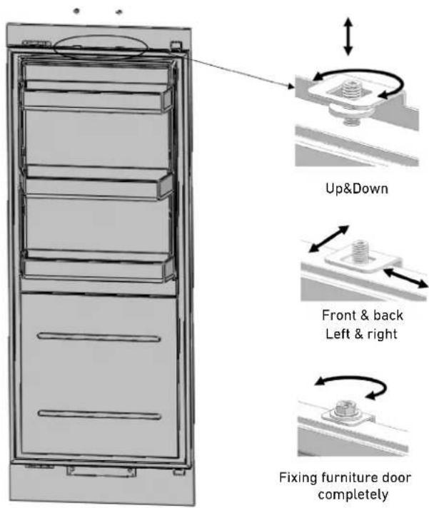
- The position of the level adjustment part (#10) must be adjusted based on the thickness of the door. It can adjust the level for 4 different door thicknesses.


NOTE:
The niche must be designed to accommodate the minimum depth requirement plus the thicker door panel, if desired. Regardless of door thickness, the maximum panel weights must always be respected, or the product warranty will be void.
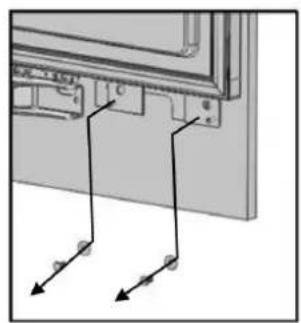
SCREWING IN THE SIDE BRACKETS
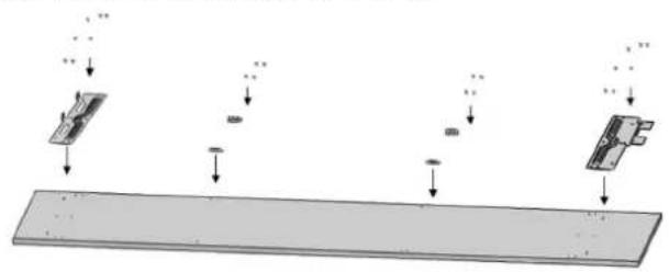
- Mount the brackets (#12) on the unit, with 2 on the top and 3 on each side. Use screws (#14) to tighten them in place.
- Use 12 long screws (#13) to join the unit to the cabinet.

WARNING:
Before screwing the side brackets into the cabinet gables, ensure the screw is shorter than the gable thickness, otherwise the finished side may be damaged.
Before beginning to screw on the side and upper brackets, make sure that the unit is connected to power,that water (if applicable) is being supplied to the appliance and that the water connection has been tested for leaks.

NOTE:
Drilling a pilot hole in the side gable for reference could make the mounting process easier.


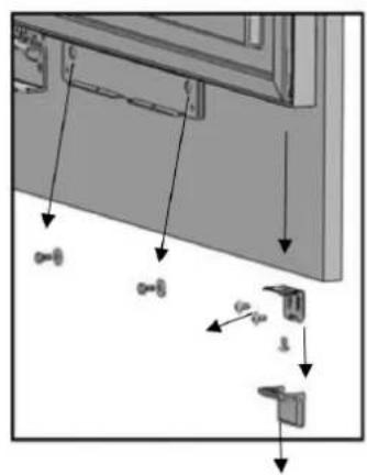
SECURING THE UPPER BRACKET
- Attach the upper bracket to the cabinet using 4 screws (#13).

NOTE:
Drilling a pilot hole in the side gable for reference could make the mounting process easier.

INSTALLING THE BOTTOM CABINET Complete the water connection
- Use a cutter to cut of any excess waterline length, allowing sufficient slack of 10^ (254 mm) to ensure an easy bend and clear connection, with no tension or potential kinks in the supply line that runs to the connector.


- Use 2 wrenches to firmly connect both the hose that runs from the supply and the connection to the valve on the refrigerator.

WARNING:
The hose that runs from the water supply must be one piece. Do not use extension hoses.

WARNING:
Make sure that the power is cut off when establishing the appliance's water connection.

WARNING:
The water valve must be closed when connecting the water hose.

WARNING:
It is recommended to keep the water valve accessible after product installation.

WARNING:
This appliance is suitable for use with a cold potable water supply only.

WARNING:
The pressure of the water system must be between 25-80 psi (1.7-5.5 Bar).

NOTE:
Once the connection is complete, you must open the water valve and make sure that there is no leakage.

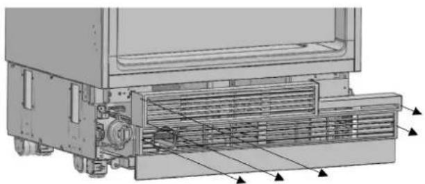
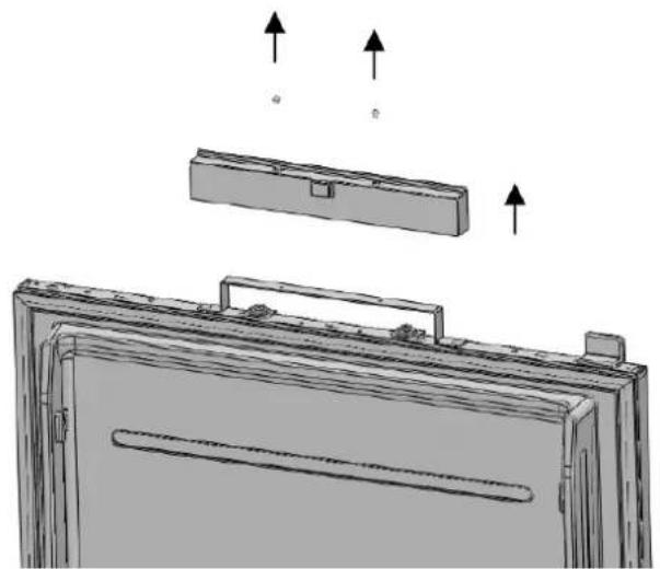
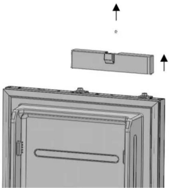
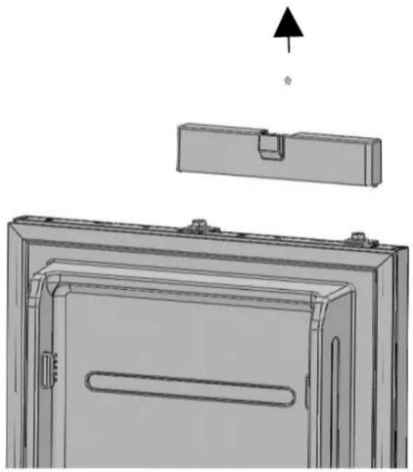
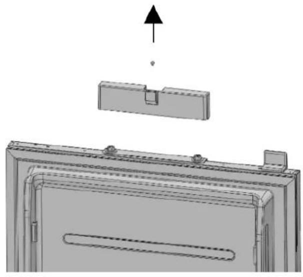
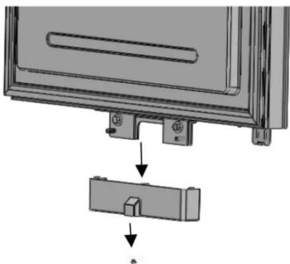
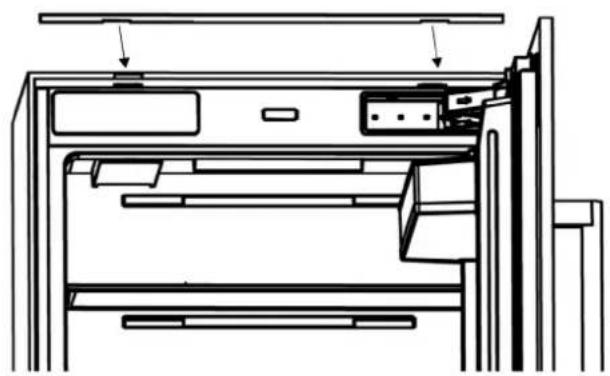
ATTACHING THE AIR VENT GRILLE
- Use 5 screws to attach the vent aperture component.

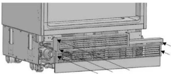

NOTE:
The lower grill can be adjusted forward or backward of 15 / 16" (24 mm) to accommodate the cabinet toe kick. Also, a piece of decorative cabinet toe kick material can be affixed to the lower grill to match the cabinets, provided there is no obstruction to vent grills and air flow.

WARNING:
If installing a one-piece cabinet toe kick across the front of the fridge, you must ensure proper air flow and no obstruction to the vent grills.
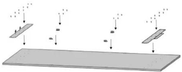
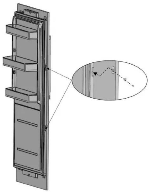
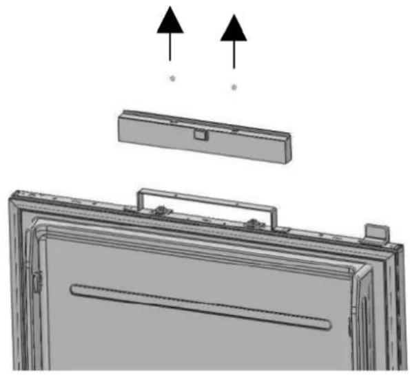
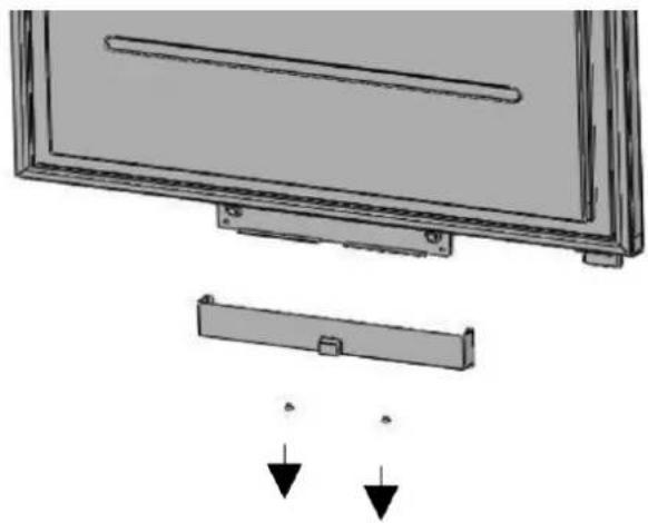
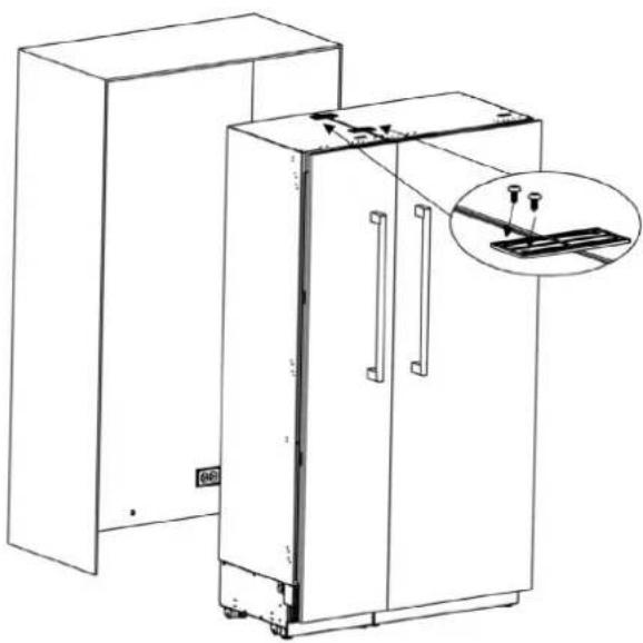
ATTACHING THE DECORATIVE TRIM COVERS
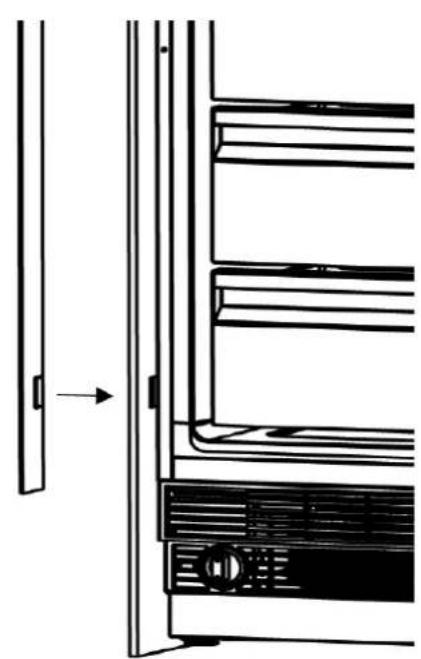
- The decorative side trim is a soft plastic material with a barbed end intended to be inserted between the cabinet gable and the appliance body (#2), onto the right/left connection brackets. Some trimming may be required to ensure the trim pieces can fit around the brackets; the thickness of the barbed end may also require trimming depending on the width of the gap between the side body and the cabinet gable.
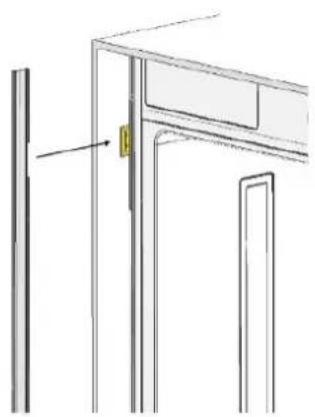
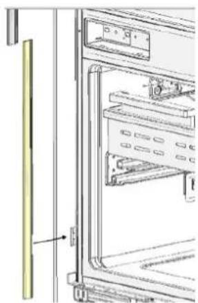
- Push in the finished trim (#1) on the upper connection bracket.

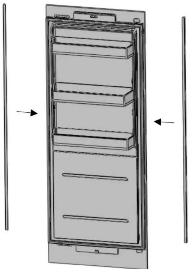
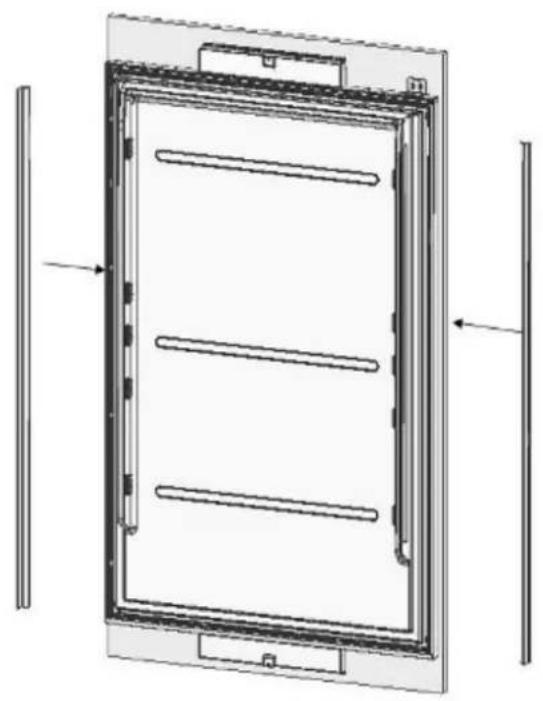
3.5 Overlay Panel Installation and Preparation
This section contains information about preparing the cabinet doors and mounting them on the product.

WARNING:
Maximum weights of the panels to be mounted on the unit are as follows:
Refrigerator Column Door: 66 lbs (30 kg)
Freezer Column Door: 66 lbs (30 kg)
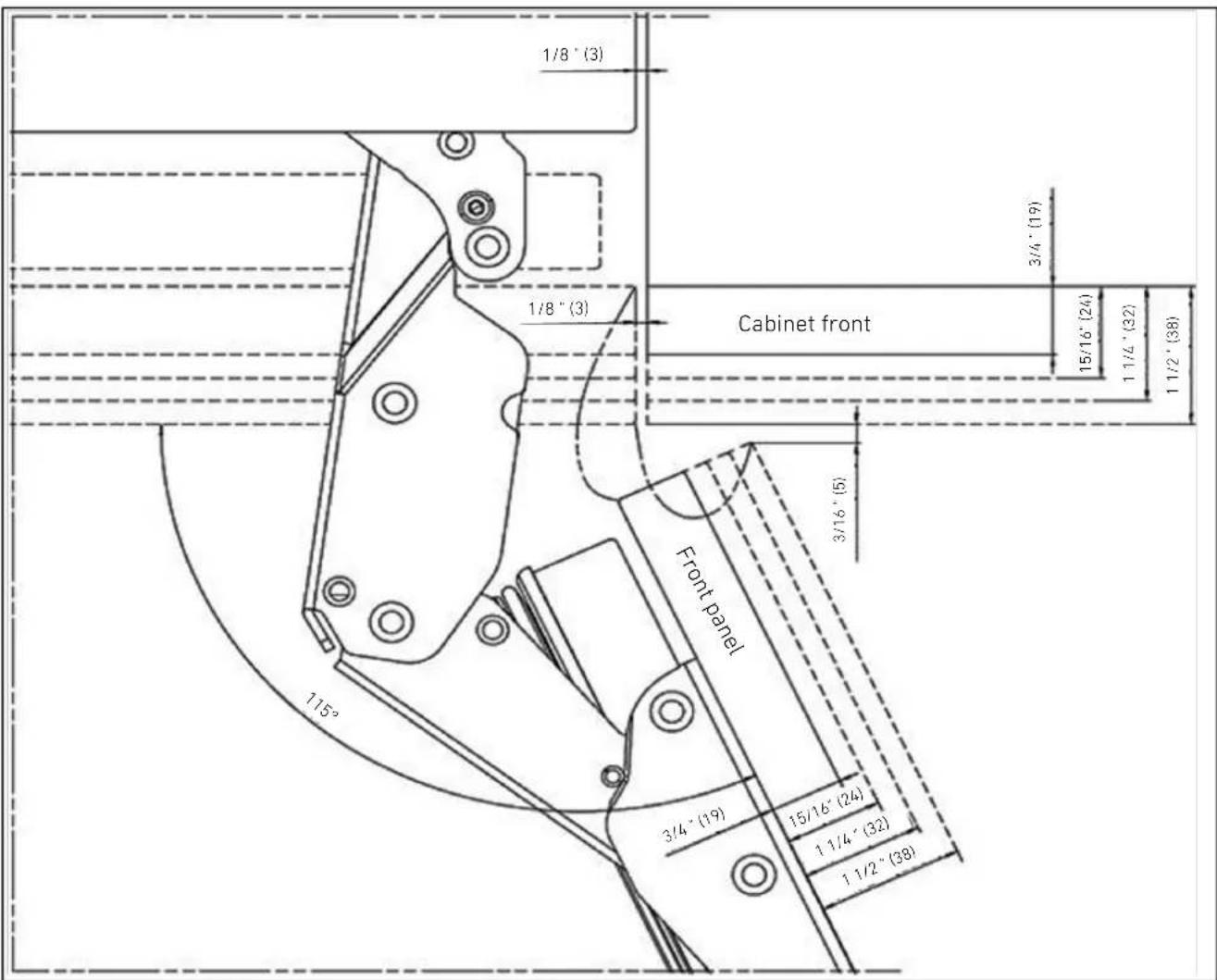
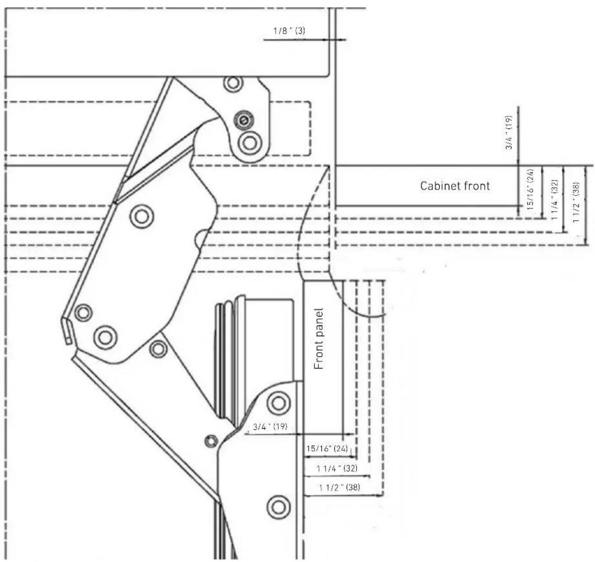
CHOOSING THE DOOR THICKNESS
- The door of your refrigerator can open to 115^ maximum. If you want the doors to open to this degree, you can choose from the thicknesses shown in the image above.

WARNING:
If the door thickness is more than 112 (38 mm), the door should not open more than 90^ . You must use a limiting pin on the hinge.
A limiting pin (part #17) is provided with the unit to prevent the door from opening beyond 90^ if necessary; it can be installed on the hinge. Door thickness allowances when using the limiting pin are shown in the diagram below.

EN
REMOVING THE OVERLAY PANEL MECHANISM COVERS
- Remove the upper screws to remove the upper cover.

REF18FCBIPRV/REF18FCBIPLV
REF24FCBIPNV
REF24RCBPNV
REF30RCBPNV
WARNING:
There is a magnet on the cover door hanger bracket. This is a functional component for product operation, because it activates the door open reed switch. Please ensure the covers do not get switched; put each back on the same bracket it was removed from. The magnet should not be switched with the lower cover.
- Remove the two screws to remove the door hanger bracket for the lower mechanism cover.

EN
REMOVING THE PANEL BRACKETS
- Remove the upper and lower adjustable panel mounting brackets from the door panel adjustment mechanisms, as shown below.
REF24FCBIPNV
REF24RCBPNV
REF30RCBPNV
REF18FCBIPRV/REF18FCBIPLV


PREPARING THE OVERLAY PANELS

NOTE:
When marking, you can use the door/drawer panel preparation template provided with the product.

REF18FCBIPRV / REF18FCBIPLV
REF24FCBIPNV
REF24RCBPNV
REF30RCBPNV

WARNING:
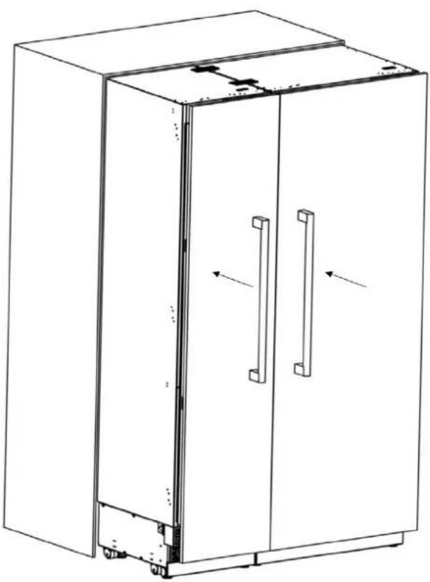
The handle mounting holes will have to be adjusted based on the handles to be used in the kitchen design.

WARNING:
The minimum door thickness must be 34 (19 mm).
REF18FCBIPRV/REF18FCBIPLV
REF24FCBIPNV
REF24RCBPNV
REF30RCBPNV

| Category | REF18FCBIPRV / REF18FCBIPLV | REF24FCBIPNV REF2 | 4RCBPNV REF30RCBPNV | |
| mm 451 * 2030 | 603 * 2030 603 * 2030 756 * 2030 | |||
| inch 17 3/4 * 79 | 15/16 23 3/4 * 79 15/16 | 23 3/4 * 79 15/16 29 3/4 * | 79 15/16 |

WARNING:
- To prevent damage to the finished surface of the panel, use screws suitable for the door panel thickness.
- Install the panel brackets using screws (#15). You can also use the template provided with the product to align these parts. It is recommended to keep this template for future reference.
The fridge door hanger sheet and fridge door upper mechanism assembly must be on the upper part of the door.
Attach the door handle to the upper door panel prior to installing the panel on the fridge. Use handle hardware that will ensure a secure connection to the panel and that will lie flush against or, in any case, not protrude from the back of the overlay panel. This may require countersinking the handle hardware into the back of the panel, as shown below. The door handle mounting screws must not protrude either.
REF18FCBIPRV / REF18FCBIPLV
REF24FCBIPNV
REF24RCBPNV
REF30RCBPNV

WARNING:
The handle mounting holes will have to be adjusted based on the handles to be used in the kitchen design.

WARNING:
The minimum door thickness must be 34 (19 mm).

WARNING:
To prevent damage to the finished surface of the panel, use screws suitable for the door thickness.
ALIGNING THE UPPER PART OF THE CUSTOM DOOR PANEL WITH BOLTS
- The custom panel for the refrigerator must be flush with the cabinet doors beside it.
To achieve this, it is necessary to adjust the 3D direction using two fixing bolts.
First, check the position of the refrigerator door in relation to the kitchen cabinets.
The distance between the door and the cabinets beside it should be 3mm (1 / 8^ ) , assuming that the door dimensions are correct.
You can now adjust the door according to this distance.

EN
ALIGNING THE LOWER PART OF THE CUSTOM DOOR PANEL WITH BOLTS.

- Use the bracket furniture door(Item No6) to join the furniture door
- Use 2screws (Item No7) and 1 screw(Item No5) to fix.


REF24FCBIPNV
REF24RCBPNV
REF30RCBPNV

3. INSTALLATION INSTRUCTIONS
- Clip the cover furniture door bracket.
REF24FCBIPNV
REF24RCBPNV
REF30RCBPNV
- Attach and screw the upper/lower decoration cover.
REF18FCBIPRV / REF18FCBIPLV


EN
- Attach and screw the upper/lower decoration cover.
REF24FCBIPNV REF24RCBPNV

- Attach and screw the upper/lower decoration cover.
REF30RCBPNV

WARNING:
You must keep these parts for future use. You will need them if you want to change the door directions.
- After the top and bottom door panel brackets are secured by installing screws, use screw(Item No8) and square washer(Item No9) to secure the center mounting bracket.
- Attach the Trim door side (Item No3)

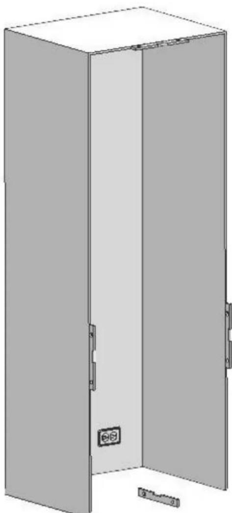
3.6 Hinge Adjustment and Reversing the Door Swing
ADJUSTING THE SPRING TENSION OF THE HINGES
- Use a drill to adjust the tension of the upper and lower hinges of the fridge door. Set the hinge adjustment screw to position "1" from position "0".


WARNING:
The door must be fully open during this adjustment.

WARNING:
The hinge tension adjustment must be performed only after the door panel has been adjusted.
REMOVING THE DOOR PANEL
- Set the tension level of the hinge to "0".

CAUTION:
Failure to set the hinge to "0" before continuing the installation may result in injury.
- Remove the side closing seals.
- Loosen the 2 screws in the upper cover of the fridge door and remove it.
- Take out the upper adjustment kits.

REF18FCBIPRV / REF18FCBIPLV
REF24FCBIPNV REF24RCBPNV
REF30RCBPNV
- Loosen the 2 screws in the lower cover of the fridge door and remove it.


REF18FCBIPRV/REF18FCBIPLV
REF24FCBIPNV REF24RCBPNV
REF30RCBPNV
- Remove the lower and upper bracket screws from the fridge.

REF18FCBIPRV/REF18FCBIPLV


REF24FCBIPNV
REF24RCBPNV
REF30RCBPNV
EN

- Remove the screw from the upper and from the lower fridge mechanism.

WARNING:
The fridge door panel will be released when these screws are removed.
You must take measures to prevent the door from falling.
You can tape the cabinet door to the inner door or ask a second person to help.
- Take off the fridge cabinet door and lay it upside down on a table top.
- You must attach the cabinet door by rotating it 180^ with respect to its current position.
REMOVING AND PREPARING THE INNER DOOR
- Remove the hinge connection screws from the hinge brackets.


CAUTION:
The door will be released when these screws are removed. You must take measures to prevent the door from falling. You can tape the cabinet door to the inner door or ask a second person to help.

Take off the fridge door and lay it on a table top, then remove the mounting components and screw them to the opposite side of the door.
- Use 2 screws to attach the hanger sheet.
EN
REPLACING THE HINGES
- Remove the Hinge Caps located at the other side where you will fix the hinges.

- Remove the lower right hinge by loosening its 2 screws and fix it to its slot at the upper left side.


AIR VENT UPPER PART DIRECTION CHANGE
- Remove the air vent part and change direction as shown in the figure.


HOW TO CHANGE AIR VENT UPPER PART DIRECTION
Air vent upper part for the right hinge

Air vent upper part for the left hinge

Air vent hinge part left
EN
- Remove the upper right hinge by loosening its 2 screws and fix it to its slot at the lower left side.

- Attach the Hinge Slot Caps removed from the left side to the Hinge Caps to the right side.
REINSTALLING THE DOOR
- Place the inner door on the refrigerator using the door seal to help hold the door in place and fasten it back onto the hinges using 4 screws.


- All freezer columns include one connection trim kit (CTXV).
CABINET CUTOUT DIMENSIONS
Please check cabinet cutout dimensions below before starting the installation.

| Configuration 18+24 18+30 24+24 24+30 30 30+30 | |||||
| “A” Dimension 42" (1066mm) 48" (1219mm) 48" (1219mm) 54" (1371mm) 60" (1524mm) |
LOCATION OF THE ELECTRICAL WIRING
Location of the electrical wiring must be within the range given below.

ATTENTION:
Do not use extension cables or two-pin adaptors and do not remove the ground terminal of the grounding cable.

ATTENTION:
A qualified electrician must ensure that the poles of the socket are connected correctly. Verify that the grounding of the socket is correct.
| Configuration 18+ | 24 18+30 24+24 24+30 | 30 30+30 | |||
| “A” Dimension 13" (330mm) 19" (482mm) 13" (330mm) 19" (482mm) 19" (482mm) | |||||
LOCATION OF THE WATER SYSTEM
The water connected to the water mains must be potable.
Location of the water system must be within the range given below.
Water system of the refrigerator must be connected to the water mains system in the house.
The user must be able to switch it on/off with the valve when necessary.
Objects that might pierce the water hoses or cause them to twist must not be present where the water line is installed.
Pressure of the water system must be between 25-80 psi (1.7-5.5 Bar).
If the water pressure exceeds 80 psi, install a pressure limiting device or water impact protector to the inlet valve.
Never install the product or operate the appliance if it is possible for the water pressure to exceed 120 psi.

ATTENTION:
Make sure that there is no water leakage when making the water connections.
Otherwise, there will be water on the floor and the furniture will get damaged.
You will need a hose with a minimum length of 60^ (1.5 meters) and a diameter of 1 / 4^ for water connections of the product during installation.
A connector that has a thread with an external diameter of . must be used to connect the hose end to the product.
Before completing the installation, make sure that water flows and there is no water leakage.
| Configuration 18+24 18+30 24+24 24+30 30 30+30 | |||||
| “A” Dimension 8" | (203mm) 8" (203mm) | 14" (356mm) 14" (356mm) | 20" (508mm) | ||

| No Part name Spec Q'ty | ||
| 1 Insulating Foil Sponge, gray, T3.0*400*1750 1 | ||
| 2 Lower Bracket T2.0, Cr+zn-coating 1 | ||
| 3 Screws M4*12 16 | ||
| 4 Upper Brackets POM 3 | ||
| 5 Central Trim PVC extrusion L=1876 1 |
INSTALLING THE UPPER AND LOWER BRACKETS
Install the Upper and Lower Brackets, as per the pictures below:

Lower bracket
Attach the Insulating Foil centered to the side of one of the refrigerator units, as per the picture below:

- Position the two refrigerators side-by-side, ensuring they are properly aligned.
- Once aligned, use screws to attach the Upper Brackets to both refrigerators. Refer to the pictures below for guidance:
- Once the refrigerators are properly aligned, secure the Lower Bracket to the other refrigerator using screws.

- Connect the power supply to the refrigerators.
- Install the water connections for the refrigerators, following the manufacturer's instructions.
- Gently push the refrigerators into their final position, making sure they are level and stable.
- Using a drill and the bit shown below, engage each of the refrigerator's adjuster shafts in turn and level the refrigerator.

WARNING:

Raise the front feet to reduce any risk of the cabinet falling frontward.
A/D -Rotate the shaft clockwise to raise the front feet
B/C -Rotate the shaft clockwise to raise the rear feet.
EN
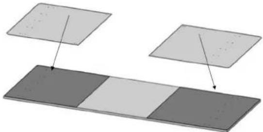
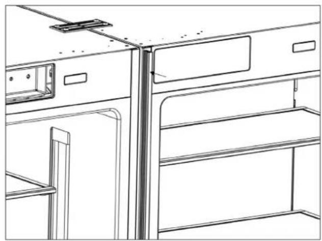
INSTALLING THE CONNECTION BRACKETS ON THE REFRIGERATOR'S SIDE WALLS
- Install the connection brackets to the refrigerator using 12 screws.


INSTALLING THE CONNECTION BRACKETS ON THE REFRIGERATOR'S TOP WALL
- Attach the connection brackets to the refrigerator using 4 screws.


INSTALLING THE LATERAL AND UPPER TRIMS
- Install the lateral trims onto the right and left connection brackets.

- Install the upper trim onto the upper connection brackets.
- Ensure that the refrigerators are properly aligned before inserting the Center Trim (part #5).
- Gently push the Center Trim between the refrigerators to securely fit it in place.
C
ES

REF18FCBIPRV
REF18FCBIPLV
REF24FCBIPNV

REF24RCBPNV
REF30RCBPNV
C

REF24RCBPNV
REF30RCBPNV
1. INFORMATIONS IMPORTANTES 125
- BEFORE INSTALLATION 7
- INSTALLATION INSTRUCTIONS 21
- Symbols and Their Meanings
- Note
- Warning
- Caution
- Disposing of the packing materials
- WARNING:
- R600a Refrigerant
- CAUTION:
- Climate class
- Food Load Bearing Capacity of the Doors
- Installation location
- Please heed the following rules:
- 2.2Cabinetry
- Ventilation
- Electrical Connection
- CAUTION: RISK OF ELECTRIC SHOCK
- Water Connection (where applicable)
- Note:
- Tool List
- Alternatives for Installation
- Preparation for Installation
- Niche Dimensions
- BEFORE INSTALLATION
- Location of the Electrical Wiring
- Location of the Water System
- Product dimensions
- Unpacking
- Removing the Connectors on the Side Wall of the Unit
- Removing the Installation Hardware
- Removing the vent hole assembly
- Before Installation
- Mounting the Anti-Tip Brackets
- Alternative anti-tip method:
- Preparing the Water Hose and the Electrical Connection
- Installation in the cabinet
- Taking the Refrigerator from the Wooden Pallet
- Placing the refrigerator into the cabinet niche.
- Adjusting the height of the refrigerator within the niche
- Adjusting the refrigerator based on the cabinet niche.
- SCREWING IN THE SIDE BRACKETS
- SECURING THE UPPER BRACKET
- INSTALLING THE BOTTOM CABINET Complete the water connection
- ATTACHING THE AIR VENT GRILLE
- ATTACHING THE DECORATIVE TRIM COVERS
- Overlay Panel Installation and Preparation
- CHOOSING THE DOOR THICKNESS
- REMOVING THE OVERLAY PANEL MECHANISM COVERS
- REMOVING THE PANEL BRACKETS
- PREPARING THE OVERLAY PANELS
- ALIGNING THE UPPER PART OF THE CUSTOM DOOR PANEL WITH BOLTS
- INSTALLATION INSTRUCTIONS
- Hinge Adjustment and Reversing the Door Swing
- ADJUSTING THE SPRING TENSION OF THE HINGES
- REMOVING THE DOOR PANEL
- REMOVING AND PREPARING THE INNER DOOR
- REPLACING THE HINGES
- AIR VENT UPPER PART DIRECTION CHANGE
- HOW TO CHANGE AIR VENT UPPER PART DIRECTION
- REINSTALLING THE DOOR
- CABINET CUTOUT DIMENSIONS
- LOCATION OF THE ELECTRICAL WIRING
- ATTENTION:
- LOCATION OF THE WATER SYSTEM
- INSTALLING THE UPPER AND LOWER BRACKETS
- INSTALLING THE CONNECTION BRACKETS ON THE REFRIGERATOR'S SIDE WALLS
- INSTALLING THE CONNECTION BRACKETS ON THE REFRIGERATOR'S TOP WALL
- INSTALLING THE LATERAL AND UPPER TRIMS
- INFORMATIONS IMPORTANTES 125
Brand : BERTAZZONI
Model : REF18FCBIPLV
Category : Refrigerator