
IR20 - Thermometer Fora - Free user manual and instructions
Find the device manual for free IR20 Fora in PDF.

| Product type | Ear / forehead infrared thermometer |
| Model | FORA IR20 (IR20c and IR20b with Bluetooth) |
| Dimensions (L x D x H) | 160.5 mm x 32.5 mm x 45.9 mm |
| Weight (with batteries) | 105.5 g |
| Power supply | 2 AAA 1.5 V alkaline batteries |
| Measurement range (ear) | 32.0 °C to 43.0 °C (89.6 °F to 109.4 °F) |
| Measurement range (skin surface) | 22.0 °C to 44.0 °C (71.6 °F to 111.2 °F) |
| Display resolution | 0.1 °C / 0.1 °F |
| Accuracy | ±0.2 °C (36-39 °C); ±0.3 °C elsewhere |
| Memory capacity | 10 recent measurements |
| Connectivity | IR20c: RS-232 port; IR20b: Bluetooth |
| Fever indicator | Red backlight for ≥38 °C (100.4 °F) |
| Operating temperature | 10 °C to 40 °C (RH ≤ 95%) |
| Storage temperature | -20 °C to 60 °C (RH ≤ 95%) |
| Maintenance and cleaning | Clean the probe with a cotton swab or soft cloth. Do not immerse. Use a dry cloth for the body. |
| Safety | Do not disassemble, do not use if damaged, avoid direct sunlight, keep out of reach of children. |
| Spare parts and repairability | Disposable probe tips available; replaceable AAA batteries; no user-serviceable parts. Contact the dealer if problems occur. |
| General information | Manufactured by ForaCare Suisse AG; standards CE, ASTM E1965-98, EN 12470-5; diagnostic medical device. |
Frequently Asked Questions - IR20 Fora
User questions about IR20 Fora
0 question about this device. Answer the ones you know or ask your own.
Ask a new question about this device
Download the instructions for your Thermometer in PDF format for free! Find your manual IR20 - Fora and take your electronic device back in hand. On this page are published all the documents necessary for the use of your device. IR20 by Fora.
USER MANUAL IR20 Fora
natural_image
Line drawings of two mobile phone models, one front and one side, showing front and side views (no text or symbols)Ear Thermometer
Owner's Manual

Sonde

Bouton Marche/Mémoire

Autocollant

natural_image
Mechanical assembly diagram showing gears and a component (no text or symbols)Étape 2
natural_image
Line drawing of a hand holding a small mechanical device (no text or symbols)REMARQUE
natural_image
Line drawing of a hand holding a small object, possibly a tool or device (no text or symbols visible)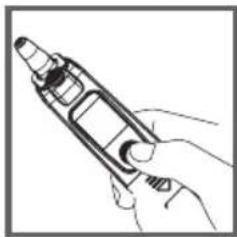
natural_image
Line drawing of a hand holding a handheld device (no text or symbols)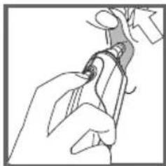
natural_image
Line drawing of a hand holding a tool, no text or symbols presentÉtape 4
natural_image
Line drawing of a hand holding an earpiece, no text or symbols present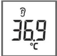
natural_image
Illustration of a hand pouring liquid into a container with an arrow indicating flow (no text or symbols)REMARQUE
natural_image
Line drawing of a hand holding a tool or device (no text or symbols)IMPORTANT SAFETY INSTRUCTIONS
English
READ THIS BEFORE USING
The following basic safety precautions should always be taken.
- Close supervision is necessary when the thermometer is used by, on, or near children, handicapped persons or invalids.
- Use the thermometer only for the intended use described in this manual.
- Do not use the thermometer if it is not working properly, or if it has suffered any damage.
- Do not use accessories which are not supplied or recommended by the manufacturer.
KEEP THESE INSTRUCTIONS IN A SAFE PLACE
Cautions and Warnings
As with any thermometer, proper technique is crucial to getting accurate temperature readings. Please read this manual thoroughly and carefully before using.
▲ Always store the thermometer in a cool and dry place: temperatures between -20^ to 60^ ( -4^ to 140^ ) relative humidity less than 95%. Avoid direct sunlight.
- Avoid dropping the thermometer from a height or strongly hitting it with a hard object.
Do not touch the probe lens.
Do not disassemble the thermometer.
Basic safety precautions should always be observed, especially when the thermometer is used on or near children and disabled persons.
This thermometer is not intended to be a substitution for consultation with your physician.
Temperature of left and right ear may differ. Always measure using the same ear.
For proper hygiene, do not share probe cover. Damaged probe cover may result in error display.
If you experience any serious incident related to this product's use, please report it to the manufacturer and
the competent authority of medical devices in your country.
A serious incident means any incident that directly or indirectly led, might have led, or might lead to any of the following:
(a) the death of a patient, user, or other people,
(b) the temporary or permanent serious deterioration of a patient's, user's or other person's state of health,
(c) a serious public health threat.
Restrictions of Use
This thermometer is clinically proven to produce accurate temperature measurements. However, please be advised if you have the following situations:
The accuracy cannot be ensured for a person with a deformity in the ear such that the thermometer probe can not be properly inserted into the ear canal.
The accuracy cannot be ensured when blood or drainage is found in the ear canal.
Take temperature from the other ear if ear drops or medications have been placed in an ear.
For a person who wears ear plug or hearing aid, remove the device and wait for 15 minutes before taking temperature.
NOTE Never try to clean inside the ears. You may accidentally damage the eardrum or its surrounding tissues. Remove excess earwax only when you can reach it with a clean cloth. Consult a physician if you suspect the presence of excess earwax.
Introduction
Thank you for choosing FORA IR20 ear thermometer. This innovative medical device relies on advanced infrared (IR) technology to measure temperature instantly. FORA IR20 ear thermometer is an elegantly designed infrared thermometer meant for your family.
Intended use
FORA IR20 ear thermometer is intended for the intermittent measurement and monitoring of human body temperature from ear canal. The device is intended for use by people of all ages at home.
How does it work
The thermometer measures the infrared heat generated by the eardrum and its surrounding tissue. The thermometer then converts it into a temperature value shown on LCD.
NOTE The thermometer does not emit any infrared signal.
Thermometer Parts
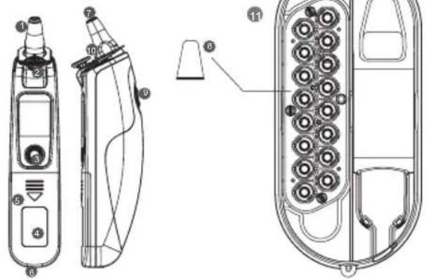
LCD Screen

Probe

Probe cover ejection button

On/Memory button

Sticker

Battery cover

Data port

Probe lens

Probe cover

Scan button

Probe cover detector

Storage Tray

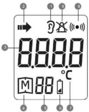
Ear temperature indicator

Temperature scanning in progress

Temperature display

Memory mode

Record numbers

Low bettery indicator

Temperature unit

Communication symbol

Non-probe cover warning
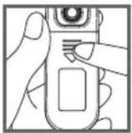
Installing/Replacing the Battery
The thermometer comes with two 1.5V AAA alkaline batteries. Replace it when "☐" appears. Please follow the steps to replace new batteries.
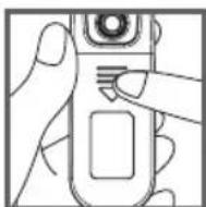
Step 1
Remove the battery cover.
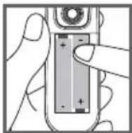
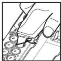
Step 2
Install the new battery in the battery compartment and press it in until the battery is firmly secured.
Step 3
Reattach the battery cover.
NOTE
Although the thermometer works when “☐” appears, we still recommend that you change the battery to obtain an accurate result.
Remove the battery if stored for a long period of time.
The battery should be kept out of reach of children. If they are swallowed, promptly see a doctor for help.
About Normal Body Temperature & Fever
Body temperature can vary from one individual/person to the next. It also varies by location on the body and different times of the day. Below shows the statistical normal ranges from different sites. Please keep in mind that temperatures measured from different sites, even at the same time, should not be directly compared.
Fever indicates that the body temperature is higher than normal. This symptom may be potentially caused by infection, overdressing or immunization. Some people may not experience fever even when they are ill. These include, but are not limited to, infants younger than 3 months old, persons with compromised immune systems, persons taking antibiotics, steroids or antipyretics (aspirin, ibuprofen, acetaminophen), or persons with certain chronic illnesses. Please consult your physician when you feel ill even if you do not have a fever.
Table 1 Body Site Normal Temperature Range
| Oral 0.6°C (1°F) or more above or below 37°C (98.6°F) |
| Rectal/ear 0.3°C to 0.6°C (0.5°F to 1°F) higher than oral temperature |
| Axillary(underarm) 0.3°C to 0.6°C (0.5°F to 1°F) lower than oral temperature |
*Body Temperature at WebMD; http://firstaid.webmd.com/body-temperature retrieved at 2010 Jan 7.
Using the Device
Hints on Taking Ear Temperture
As with other of thermometer, you may observe slight variations in consecutive measurements. It is recommended that you take 3 temperature readings and use the highest one for the following situations:
▲ Infants younger than 3 months old.
Children younger than 3 years old and who have a compromised immune system and the presence / absence of fever is critical.
When you are learning to use the thermometer.
Do not take a reading while eating and/or talking. Wait 30 minutes after any of the following situations before taking a measurement:
When you have your ear covered.
After exercising, swimming, or taking a bath. When expose to extreme temperature.
To take accurate readings, the ear must be free from excess earwax build-up.
Installing/Replacing the Probe Cover
Step 1
Check if the probe cover is clean and new. Press the infrared probe into the cartridge.
natural_image
Line drawing of a mechanical assembly with gears and a handle (no text or symbols)Step 2
Secure the cover to the probe and remove it from cartridge.
natural_image
Line drawing of a hand holding a small mechanical component (no text or symbols)NOTE
If a probe cover is not attached on the probe, LCD will show "X" until a new probe cover is firmly attached to the probe.
The used probe cover should be replaced with a new and clean one after each measurement to ensure accuracy reading.
For hygiene use, attach a new probe cover each time and do not touch its tip.
Taking Ear Temperature
Step 1
Make sure probe cover is firmly attached to the probe.
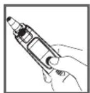
Step 2
Press and release the On/Memory button to turn on the thermometer. When ready, the thermometer displays the last measurement.
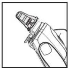
Step 3
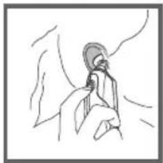
Stretch your ear canal by pulling your ear backwards and upwards and carefully insert the thermometer into the ear.
natural_image
Line drawing of a hand holding a pen or stylus (no text or symbols)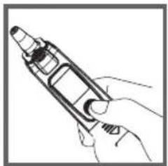
natural_image
Line drawing of a hand holding a handheld electronic device (no text or symbols visible)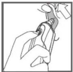
natural_image
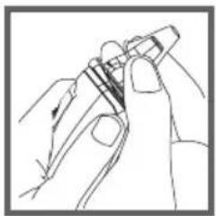
Line drawing of a hand holding a tool, no text or symbols presentStep 4
Press and release the Scan button. Do not remove the thermometer until it beeps.
Step 5
Read the result. " 🔍 " is shown together with a temperature value.
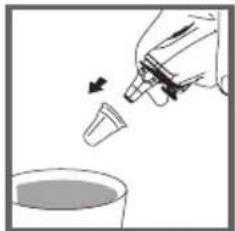
Step 6
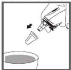
Discard used probe cover in a trash can by pressing probe cover ejection button.
NOTE
Turn off the thermometer by pressing On/Memory button twice. It will automatically turn off if left idle for 3 minutes.
natural_image
Line drawing of a hand holding an earpiece, no text or symbols present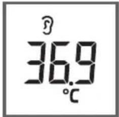
natural_image
Illustration of a hand pouring liquid into a container with an arrow indicating flow (no text or symbols)Recalling the Memory
Your thermometer stores 10 recent readings in the memory.
Step 1
Be sure the thermometer is OFF before recalling this memory.
Step 2
Press the On/Memory button to turn on the thermometer.
Step 3
Press the On/Memory button for 3 seconds to enter memory mode.
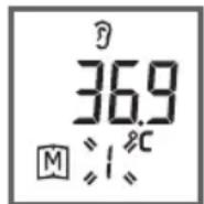
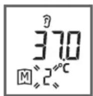
Each time you press the On/Memory button, a result will be displayed in the order of dates (latest result shown first), together with "M" and number (from 1 to 10).
When the memory is full, the oldest result is deleted as the new one added. When the last record is displayed in the LCD, press On/Memory button again to return the first record.
Step 4
Exit the memory.
Press the Scan button and LCD will show the latest results with flashing “■” . Then press On/Memory button again and LCD will show “OFF” to exit memory.
NOTE When using the thermometer for the first time, the first memory result will display 0.0^ C. It indicates that there are no test results in memory.
Viewing Results on a Personal Computer and Device
Results in memory can be transmitted to the personal computer by either cable or wireless connection for FORA IR20b/IR20c respectively. Accessories needed to activate this function are:
Health Care Software System: a software downloaded from ForaCare's website (www.foracare.ch)
Interface Cable: an optional accessory for FORA IR20c.
Please contact your local customer service for above accessories.
Transmitting data via Cable (FORA IR20c)
Step 1 Install Software
Install Health Care System Software on your computer by following the instructions provided on ForaCare's website.
Step 2 Connect to Personal Computer
Connect the interface cable to a serial port on the back of your computer. With the thermometer turned off, connect the interface cable to the data port located at the bottom of the thermometer. Then “PCL” will appear in the display, indicating that the thermometer is ready to transmit data.
Step 3 Transmit Data
Follow the instructions provided in the software to transmit data. Results transmitted will include date and time. Remove the cable and the thermometer will automatically turn off.
Transmitting data via Bluetooth (FORA IR20b)
Step 1
Download the application "iFORA MP" to your device with an iOS or Android system.

Step 2
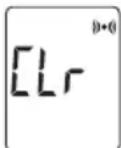
Turn on the meter, press and hold the On/ Memory and Scan buttons simultaneously for 3 seconds until "CLr" appears on the display. Your meter is now in pairing mode, the Bluetooth indicator flashes in blue.
Bluetooth Indicator (IR20b)
| Bluetooth Indicator | Description |
| Flash fast | The meter is searching the device of Bluetooth signal. |
| Flash slowly | The meter is pairing with the device of Bluetooth. |
| Lit solid | The meter is transmitting the data now the connection is completed. |
Step 3
Turn on the App, and start to pair your device.
Step 4
Make sure your IR20b is already paired with your device (IR20b's Bluetooth indicator lit solid).
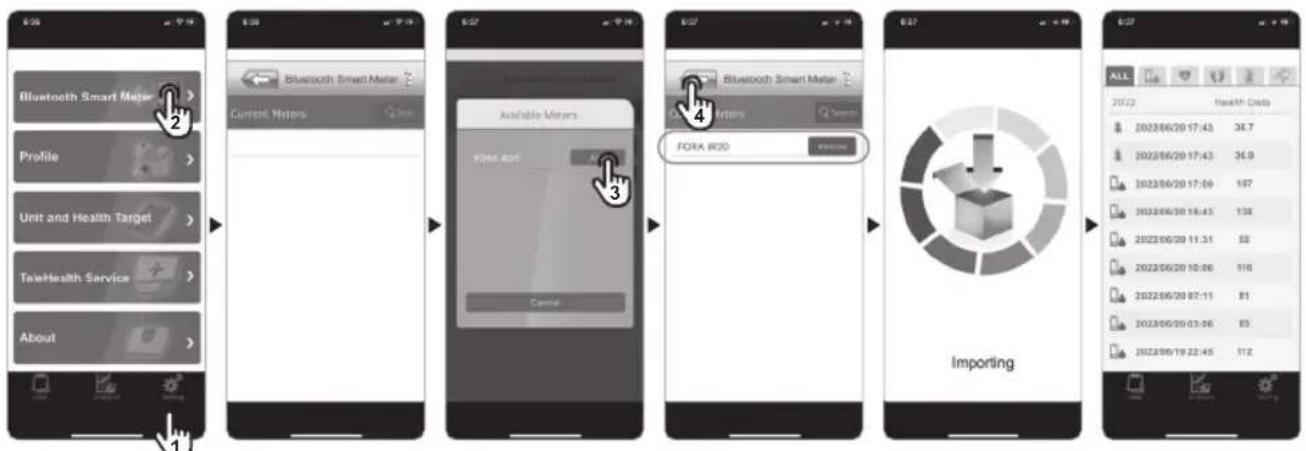
Step 5
After successfully pairing the meter with your mobile device, the Bluetooth function of the meter will be activated automatically after each measurement. The meter is ready for transmitting the data to your app.
NOTE
While the thermometer is connected to the PC or the App, it is unable to perform a test.
Care & Cleaning
- Keep the probe clean, as earwax and grease build up may affect the measurement.
The probe tip is the most delicate part of the thermometer. It has to be clean and intact to ensure accurate readings. Very gently wipe the surface with a cotton swab.
The body of the thermometer is not water-resistant. Never put the thermometer under a running tap or submerge it into water. Use a soft and dry cloth to clean it. Do not use abrasive cleaners. - Store the thermometer in a cool and dry location. Free from dust and away from direct sunlight.
Fever Indicator
When the measurement is equal or over 38^ C (100.4°F), red backlight is shown together with the result. The red backlight will last for 3 seconds and turn off.
natural_image
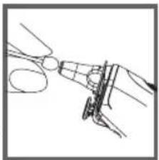
Line drawing of a hand using scissors to cut a circular object (no text or symbols)Troubleshooting
The table below shows problems you may encounter. All error messages below would be shown together with red backlight. Please follow "what to do" to resolve problems. If the problem still exists, please call your local dealer for help.
| Message What it means What to do | |||
 | Room temperature is below 10°C. | Put the thermometer under operating temperature range of 10°C to 40°C (50°F to 104°F). | |
 | Room temperature is above 40°C. | Put the thermometer under operating temperature range of 10°C to 40°C (50°F to 104°F). | |
 |  | You are not using a probe cover while measuring ear temperature. | Please place the probe cover into the probe again. |
 |  | Problem with the thermometer. | Review the instructions and re-start the measurement procedure. If the above steps do not work, please contact the dealer. |
 |  | ||
 | The battery is low and " 🔍" appears on LCD. | Please replace the batteries as soon as possible. |
 | Appears when the batteries can't provide enough power for a test. | Please replace new batteries. |
 | Temperature measurement falls outside the displayed temperature range: (ear temperature range from 32°C to 43°C, skin/surface scan temperature range from 22°C to 44°C.) | Please follow this manual to take a reading again. |
Specifications
| Dimensions 160.5mm (L) x 32.5mm (W) x 45.9mm (H) |
| Weight 105.5g (include 2 x1.5V AAA batteries) |
| Battery 2 x 1.5V AAA alkaline batteries |
| External output RS-232 (IR20c) / Bluetooth(IR20b) |
| Displayed 32°C to 43°C (89.6°F to 109.4°F) temperature range |
| Display resolution 0.1°C / 0.1°F |
| Accuracy | Meet the accuracy requirement specified in ASTM E1965-98 ± 0.2^ ( ± 0.4^ ) for the range of 36.0^ to 39.0^ ( 96.8^ to 102.2^ ) ± 0.3^ ( ± 0.5^ ) from 34.0^ to 35.9^ ( 93.2^ to 96.6^ ) and from 39.1^ to 42.2^ ( 102.4^ to 108.0^ ) |
| Temperature unit °C / °F | |
| Operating temperature range | 10^ to 40^ ( 50^ to 104^ ) |
| Operating humidity 95% RH or less | |
| Storage temperature range | -20^ to 60^ ( -4^ to 140^ ) |
| Storage humidity 95% RH or less | |
| Memory capacity 10 measurements | |
The specifications may be changed without prior notice.
This device has been tested to meet the electrical and safety requirements of: ASTM E1965-98, EN 12470-5, EN 60601-1-2:2007/AC:2010, EN 60601-1-4:1996, EN 60601-1-6:2010, EN 301489-17, EN 300328.
Symbol Information
| Symbol Referent | |
 | Consult instructions for use |
 | Manufacturer |
 | Serial number |
 | Caution |
 | Type BF Equipment |
 | CE Mark |
 | Dispose of or recycle the electrical wastes according to local regulations |
 | Temperature limitation |
 | Humidity limitation |
| [EHW2C]P | Authorised representative in the European Union |
 | Medical Device |
 | Unique Device Identification |
 | Importer |
 | Distributor |
Meter Disposal
The used meter should be treated as contaminated and may carry a risk of infection during measurement. The batteries in this used meter should be removed and the meter should be disposed in accordance with local regulations.
WARRANTY TERMS AND CONDITIONS
With respect to disposable products, ForaCare Suisse warrants to the original purchaser that, at time of delivery, each standard product manufactured by ForaCare Suisse shall be free of defects in material and workmanship and, when used for the purposes and indications described on the labeling, is fit for the purposes and indications described on the labeling. All warranties for a product shall expire as of the product expiration date, or if none, after two (2) year from the original date of purchase, as long as it has not been modified, altered, or misused. ForaCare Suisse warranty hereunder shall not apply if:
(i) a product is not used in accordance with its instructions or if it is used for a purpose not indicated on the labeling; (ii) any repairs, alterations or other work has been performed by the buyer or others on such item, other than work performed with ForaCare Suisse's authorisation and according to its approved procedures; or (iii) the alleged defect is a result of abuse, misuse, improper maintenance, accident or the negligence of any party other than ForaCare Suisse. The warranty set forth herein is conditioned upon proper storage, installation, use and maintenance in accordance with applicable written recommendations of ForaCare Suisse.
The warranty furnished hereunder does not extend to damage items purchased hereunder resulting in whole or in part from the use of components, accessories, parts or supplies not furnished by ForaCare Suisse.
Warning: Medical electrical equipment needs special precautions regarding EMC and needs to be installed according to the EMC information provided. Careful consideration of this information is essential when stacking or collocating equipment and when routing cables and accessories.
Warning: RF mobile communications equipment can affect medical electrical equipment.
| Recommended separation distance between portable and mobile RF communications equipment and FORA IR20 | |||
| FORA IR20 is intended for use in an electromagnetic environment (for home healthcare and professional healthcare) in which radiated RF disturbances are controlled. The customer or the user of FORA IR20 can help prevent electromagnetic interference by maintaining a minimum distance between the portable and mobile RF communications equipment (transmitters) and FORA IR20 as recommended below, depending on the maximum output power of the communications equipment. | |||
| Rated maximum output power of transmitter W | Separation distance according to frequency of transmitter m | ||
| 150 kHz to 80 MHz d =1,2√P | 80 MHz to 800 MHz d =1,2√P | 800 MHz to 2,7 GHz d =2,3√P | |
| 0,01 N/A 0,12 0,23 | |||
| 0,1 N/A 0,38 0,73 | |||
| 1 N/A 1,2 2,3 | |||
| 10 N/A 3,8 7,3 | |||
| 100 N/A 12 23 | |||
| For transmitters rated at a maximum output power not listed above, the recommended separation distance d in meters (m) can be estimated using the equation applicable to the frequency of the transmitter, where p is the maximum output power rating of the transmitter in watts (W) depending on the transmitter manufacturer.NOTE 1 At 80 MHz and 800 MHz, the separation distance for the higher frequency range applies.NOTE 2 These guidelines may not apply to all situations. Electromagnetic propagation is affected by absorption and reflection from structures, objects and people. | |||
| Manufacturer's declaration-electromagnetic emissions | |||
| FORA IR20 is intended for use in the electromagnetic environment (for home healthcare and professional healthcare) specified below.The customer or the user of FORA IR20 should assure that it is used in such an environment. | |||
| Emission test Compliance | Electromagnetic environment-guidance(for home healthcare and professional healthcare) | ||
| RF emissions CISPR 11 Group 1 | FORA IR20 uses RF energy only for internal use. Therefore, its RF emissions are very low and are not likely to cause any interference from nearby electronic equipment. | ||
| RF emissions CISPR 11 Class B | FORA IR20 is suitable for use in all establishments, including domestic establishments and those directly connected to the public low-voltage power supply network that supplies buildings used for domestic purposes. | ||
| Harmonic emissionsIEC 61000-3-2 | Not applicable | ||
| Voltage fluctuations/flicker emissionsIEC 61000-3-3 | Not applicable | ||
| Manufacturer's declaration-electromagnetic immunity | |||||||
| FORA IR20 is intended for use in the electromagnetic environment (for home healthcare and professional healthcare) specified below.The customer or the user of FORA IR20 should assure that it is used in the environment specified below. | |||||||
| Immunity test IEC 60601 | test level | Compliance level Electromagnetic environment-guidance(for home healthcare and professional healthcare environment) | |||||
| Electrostatic discharge(ESD) IEC 61000-4-2 | Contact: ±8 kVAir ±2 kV, ±4 kV, ±8 kV, ±15 kV | Contact: ±8 kVAir ±2 kV, ±4kV, ±8 kV,±15 kV | Floors should be wood, concrete or ceramic tile. If floors are covered with synthetic material, the relative humidity should be at least 30 %. | ||||
| Electrical fast transient/burstIEC 61000-4-4 | ±2 kV for power supply lines±1 kV for input/output lines | Not applicableNot applicable | Mains power quality should be that of a typical home and professional healthcare environment. | ||||
| Surge IEC 61000-4-5 ±0.5 kV | ±1 kV line(s) to line(s)±0.5 kV, ±1 kV, ±2 kV line(s)to earth | Not applicableNot applicable | Mains power quality should be that of a typical home and professional healthcare environment. | ||||
| Voltage Dips, shortinterruptions and voltagevariations on power supplyinput linesIEC 61000-4-11 | Voltage dips:0 % U_ ; 0,5 cycle0 % U_ ; 1 cycle70 % U_ ; 25/30 cyclesVoltage interruptions:0 % U_ ; 250/300 cycle | Voltage dips:Not applicableNot applicableNot applicableVoltage interruptions:Not applicable | Mains power quality should be that of a typical home healthcare and professional healthcare environment. If the user of FORA IR20 requires continued operation during power mains interruptions, it is recommended that FORA IR20 be powered from an uninterruptible power supply or a battery. | ||||
| Power frequency (50, 60 Hz)magnetic fieldIEC 61000-4-8 | 30 A/m50 Hz or 60 Hz | 30 A/m50 Hz and 60 Hz | FORA IR20 power frequency magnetic fields should be at levels characteristic of a typical location in a typical home healthcare and professional healthcare environment. | ||||
| NOTE U_ is the a.c. mains voltage prior to application of the test level. | |||||||
| Manufacturer's declaration-electromagnetic immunity | |||||||
| FORA IR20 is intended for use in the electromagnetic environment (for home healthcare and professional healthcare) specified below.The customer or the user of FORA IR20 should assure that it is used in the environment specified below. | |||||||
| Immunity test IEC 60601test level | Compliance level Ellectromagnetic environment-guidance(for home healthcare and professional healthcare environment) | ||||||
| Conducted RFIEC 61000-4-6Radiated RFIEC 61000-4-3 | 3 Vrms:0,15 MHz – 80 MHz6 Vrms:in ISM and amateurradio bands between0,15 MHz and 80 MHz80 % AM at 1 kHz10 V/m80 MHz – 2,7 GHz80 % AM at 1 kHz | Not applicableNot applicable10 V/m80 MHz – 2,7 GHz80 % AM at 1 kHz | Portable and mobile RF communications equipment must not be used close to any partsof FORA IR20 including cables, other than the recommended separation distance calculated fromthe equation applicable to the frequency of the transmitter.Recommended separation distance:d = 1,2 √Pd = 1,2 √P 80MHz to 800 MHzd = 2,3 √P 800MHz to 2,7 GHzWhere P is the maximum output power rating of the transmitter in watts (W) according to thetransmitter manufacturer and d is the recommended separation distance in metres (m).Field strengths from fixed RF transmitters, as determined by an electromagnetic site survey, a)should be less than the compliance level in each frequency range.b)Interference may occur in the vicinity of equipment marked with the following symbol: | ||||
| NOTE 1 At 80 MHz and 800 MHz, the higher frequency range applies.NOTE 2 These guidelines may not apply to all situations. Electromagnetic propagation is affected by absorption and reflection from structures, objects and people. | |||||||
| a) Field strengths from fixed transmitters, such as base stations for radio (cellular/cordless) telephones and land mobile radios, amateur radio, AM and FMradio broadcast and TV broadcast cannot be predicted theoretically with accuracy. To assess the electromagnetic environment due to fixed RF transmitters,an electromagnetic site survey should be considered. If the measured field strength in the location in which FORA IR20 is used exceeds the applicable RFcompliance level above, FORA IR20 should be observed to verify normal operation. If abnormal performance is observed, additional measures may benecessary, such as re-orienting or relocating FORA IR20.b) Over the frequency range 150 kHz to 80 MHz, field strengths should be less than 3 V/m. | |||||||
| Manufacturer's declaration-electromagnetic immunityTest specifications for ENCLOSURE PORT IMMUNITY to RF wireless communications equipment | |||||||
| FORA IR20 is intended for use in the electromagnetic environment (for home healthcare and professional healthcare) specified below.The customer or the user of FORA IR20 should assure that it is used in such an environment. | |||||||
| Test frequency (MHz) | Band a)(MHz) | Service a) | Modulation b) | Maximum power (W) | Distance (m) | IMMUNITY TEST LEVEL (V/m) | Compliance LEVEL (V/m) (for home and professional healthcare) |
| 385 380 | 390 TETRA 400 | Pulse modulation b)18 Hz | 1,8 0,3 | 27 27 | |||
| 450 430 | 47 GMRS 460, | FRS 460 | FM c) ± 5 kHz deviation1 kHz sine | 2 0,3 | 28 28 | ||
| 710 | 704 – 787 LTE Band 13, 17 | Pulse modulation b)217 Hz | 0,2 0,3 | 9 9745 | |||
| 780 | |||||||
| 810 | 800 – 960 | GSM 800/900, TETRA 800, iDEN820, CDMA 850, LTE Band 5 | Pulse modulation b)18 Hz | 2 0,3 | 28 28870 | ||
| 930 | |||||||
| 1 720 | 1 700 – 1 990 | GSM 1800; CDMA 1900;GSM 1900; DECT;LTE Band 1, 3, 4, 25; UMTS | Pulse modulation b)217 Hz | 2 0,3 | 28 281 845 | ||
| 1 970 | |||||||
| 2 450 2 400 | -2 570 | Bluetooth, WLAN,802.11 b/g/n, RFID 2450,LTE Band 7 | Pulse modulation b)217 Hz | 2 0,3 | 28 28 | ||
| 5 240 | 5 100 – 5 800 | WLAN 802.11 a/n | Pulse modulation b)217 Hz | 0,2 0,3 | 9 9 | ||
| 5 785 | |||||||
| NOTE To achieve the IMMUNITY TEST LEVEL, the distance between the transmitting antenna and the ME EQUIPMENT or ME SYSTEM may be reduced to 1 m.The 1 m test distance is permitted by IEC 61000-4-3. | |||||||
| a) For some services, only the uplink frequencies are included.b) The carrier shall be modulated using a 50 % duty cycle square wave signal.c) As an alternative to FM modulation, 50 % pulse modulation at 18 Hz may be used because while it does not represent actual modulation, it would be worst case. | |||||||
FORA® IR20
- Étape 2
- REMARQUE
- Étape 4
- IMPORTANT SAFETY INSTRUCTIONS
- English
- READ THIS BEFORE USING
- Cautions and Warnings
- Restrictions of Use
- Introduction
- Intended use
- How does it work
- Installing/Replacing the Battery
- Step 1
- Step 2
- Step 3
- NOTE
- About Normal Body Temperature & Fever
- Using the Device
- Hints on Taking Ear Temperture
- Installing/Replacing the Probe Cover
- Taking Ear Temperature
- Step 4
- Step 5
- Step 6
- Recalling the Memory
- Viewing Results on a Personal Computer and Device
- Transmitting data via Cable (FORA IR20c)
- Step 1 Install Software
- Step 2 Connect to Personal Computer
- Step 3 Transmit Data
- Transmitting data via Bluetooth (FORA IR20b)
- Care & Cleaning
- Fever Indicator
- Troubleshooting
- Symbol Information
- Meter Disposal
- WARRANTY TERMS AND CONDITIONS
- FORA® IR20
Brand : Fora
Model : IR20
Category : Thermometer