TI2800.1 - Receiver PHOENIX GOLD - Free user manual and instructions
Find the device manual for free TI2800.1 PHOENIX GOLD in PDF.

User questions about TI2800.1 PHOENIX GOLD
0 question about this device. Answer the ones you know or ask your own.
Ask a new question about this device
Download the instructions for your Receiver in PDF format for free! Find your manual TI2800.1 - PHOENIX GOLD and take your electronic device back in hand. On this page are published all the documents necessary for the use of your device. TI2800.1 by PHOENIX GOLD.
USER MANUAL TI2800.1 PHOENIX GOLD
• High Efficiency Class D Topology
- Compact Size for Easy Installation
• Balanced Differential Input Circuitry
• Audiophile NJM2068M Operational Amplifiers
• Ultra High Speed IR Class D Chipset
• High, Band and Low Pass Crossovers
• ADAPT Power Management System
• Surface Mount Component Technology
- Direct Insert Power and Speaker Terminals
• Audio Precision Quality Control Verification
• High Temperature Plexiglass cover
• Signal Clipping Indicators
• RMD - Remote Monitoring Display Port
- RBCF- Remote Subwoofer Level Control included (Ti2 1600.5)
Características:
| Frequency Response: ± 1dB from 20Hz to 20kHzSignal to Noise Ratio: >100dBCrossover Slopes: 12dB per OctaveFront High/Low Pass Crossover Range: 45Hz to 4kHzRear High Pass Crossover Range: 20Hz to 4kHzRear Low Pass Crossover Range: 40Hz to 4kHzLow Level Input Range: 200 millivolts to 8 voltsLowest Recommend Load: 4 ohms Bridged/2 ohms StereoTypical Efficiency: 80%Damping Factor Greater than 200 | RMS Power Output 150w x 4 @ 4 ohms Stereo250w x 4 @ 2 ohms Stereo500w x 2 @ 4 ohms BridgedPower/Ground Wire Size: 4 GaugeRecommend Power Wire Fuse: 80aDimensions: 11.7" L x 7.1" W x 2.0" H296mm L x 180mm W x 52mm H |
Ti2 1600.5 SPECIFICATIONS
| FRONT AND REAR CHANNELS: | |||
| Frequency Response: | ±1dB from 20Hz to 20kHz | RMS Power Output | 125w x 4 @ 4 ohms Stereo |
| Signal to Noise Ratio: | >100dB | 200w x 4 @ 2 ohms Stereo | |
| Crossover Slopes: | 12dB per Octave | 400w x 2 @ 4 ohms Bridged | |
| Front High Pass Crossover Range: | 20Hz to 4kHz | ||
| Rear High Pass Crossover Range: | 20Hz to 4kHz | ||
| Rear Low Pass Crossover Range: | 40Hz to 4kHz | ||
| Low Level Input Range: | 200 millivolts to 8 volts | ||
| Lowest Recommend Load: | 4 ohms Bridged/2 ohms Stereo | ||
| Typical Efficiency: | 80% | ||
| Damping Factor | Greater than 200 | ||
SUBWOOFER CHANNEL:
| Frequency Response: | ±1dB from 20Hz to 300Hz | RMS Power Output | 500w x 1 @ 4 ohms |
| Signal to Noise Ratio: | >100dB | 800w x 1 @ 2 ohms | |
| Crossover Slopes: | 12dB per Octave | ||
| Low Pass Crossover Range: | 20Hz to 300Hz | ||
| Subsonic Crossover Range: 10Hz to 50Hz | Recommend Power Wire Fuse: | 100a | |
| Variable Phase: | 0 to 180 degrees | Power/Ground Wire Size: 4 Gauge | |
| Low Level Input Range: | 200 millivolts to 8 volts | Dimensions: | 14.4" L x 7.1" W x 2.0" H |
| Lowest Recommend Load: 2 ohms | 366mm L x 180mm W x 52mm H | ||
| Typical Efficiency: | 80% | ||
| Damping Factor: | Greater than 200 | ||
POWER OUTPUT NOTE: A power birth certificate is included for each amplifier. Ti2 amplifiers are conservatively rated and will exceed their RMS power rating shown here. All RMS power ratings and measurements are at 14.4 volts with no more than 1% THD. Ti2 1000.4 and Ti2 1600.5 feature ADAPT technology which provides the same power output from 11 to 15 volts with music material.
BALANCED DIFFERENTIAL INPUTS
A Provides maximum rejection of unwanted noise from upstream components.
Audiophile NJM2068M OP-AMPS
Most mobile amplifiers today use the standard NJM4558 op-amp which has a bandwidth of 3MHz, slew rate of 1V/uSec and noise level of 1.4uV. The NJM2068M is simply a better performer with a bandwidth of 19MHz, slew rate of 6V/uSec and noise level of .44uV.
The result is quieter, faster and wider bandwidth performance that ensures the original music material is reproduced as accurately as possible.
ULTRA HIGH SPEED IR CLASS D CHIPSET
State of the art IR20957 chipset switches at more than 300kHz for blistering audio performance. All four or five chipsets are sync'd together in unison to eliminate unwanted harmonics or distortion.
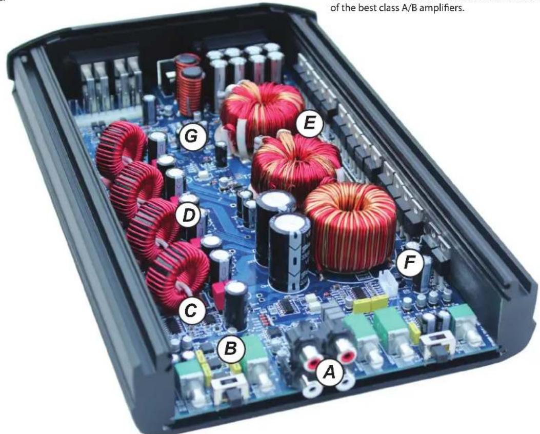
POST FILTER FEEDBACK
Feedback is when part of the output signal is "fed back" into the original signal to ensure stability and accurate sound. Class D amplifiers use output filters (see the 4 vertical coils below), but most DO NOT INCLUDE these filters in the feedback loop. Ti2 amplifiers INCLUDE or take feedback after its passed through these filters. The result is more accurate sound that rivals some of the best class A/B amplifiers.
text_image
of the best class A/B amplifiers. G E D C B AADAPT POWER MANAGEMENT SYSTEM
Full power output from 11 to 15 volts: ADAPT delivers the same output power regardless of the vehicle's electrical system voltage. Instantaneous or long term voltage drops have no effect on the amplifier's power output. This means more dynamic and less distorted audio output.
Dual power modes provide maximum efficiency: ADAPT seamlessly optimizes the power supply and Class D operating circuitry by adapting to the end user's listening habits. When the ADAPT circuit senses lower signal levels, it will automatically optimize the amplifier's power supply and Class D circuitry to a low power mode that maximizes efficiency and minimizes heat to almost zero. As a signal increase is detected the amplifier instantly shifts into a high power mode, where the power supply and Class D sections are now optimized to deliver massive power and headroom for those demanding listening sessions. The amplifier is constantly monitoring and adapting between these modes which results in higher overall efficiency, much lower operating temperatures and rock solid reliability.
THERMAL ROLLBACK CIRCUIT
Under most conditions, Ti2 amplifiers generate moderate to low heat. However, if extreme conditions exist, as temperatures rise the amplifier will automatically adjust the power output, so your music continues to play. These changes are inaudible and vastly reduce the chance for any thermal shutdown events.
LOW EMI CIRCUIT BOARD DESIGN
Most class D amplifiers can emit EMI noise that can cause problems with AM/FM reception or other devices in the vehicle. Ti2 amplifiers have undergone intense real world engineering and testing to vastly reduce or eliminate these issues. Careful PCB layout using four layers (most amplifiers feature just two) along with many key filters ensures a very low possibility of any interference issues.
T12 1000.4
4 CHANNEL POWER AMPLIFIER
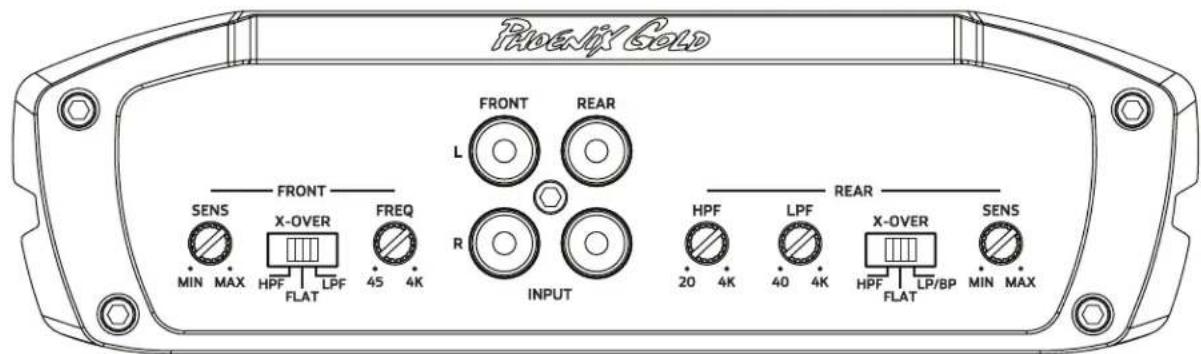
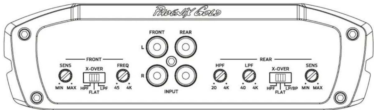
FRONT AND REAR INPUTS
Connect preamp signal cables from headunit to these inputs. The front and rear inputs must be used, if only the front input is used then the rear speaker outputs will have no output signal.
Controls the crossover points for the speaker outputs.
SENS
Used to reach maximum amplifier power with a wide variety of headunits.
X-OVER CONFIG
FLAT: Crossovers are turned off
HPF: High pass crossover is on
LPF: Low pass crossover is on
LP/BP: Low and high pass crossovers are both on, creating a Bandpass (BP) filter for midbass/midrange drivers. If running a subwoofer the HPF now becomes a subsonic filter, to turn off the HPF/subsonic filter set it to 20Hz.
Note: The front HP and rear LP crossovers extend to 4kHz, so its possible to run a component speaker system fully active. The tweeters would be powered by the front channels and the midbasses by the rear channels. Be sure to check with your speaker's manufacture for the correct tweeter and midbass crossover points to avoid speaker damage.
text_image
Phoenix Gold FRONT REAR L SENS FRONT X-OVER FREQ MIN MAX HPF FLAT 45 4K R INPUT HPF LPF X-OVER REAR 20 4K 40 4K HPF FLAT LP/BP MIN MAX MIN MAX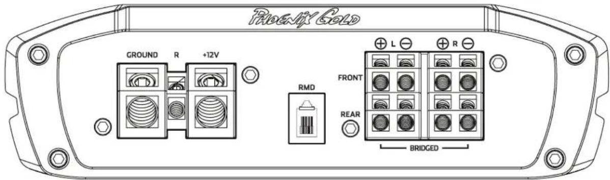
text_image
Phoenix Gold GROUND R +12V RMD FRONT REAR L R BRIDGED+12V
This must be connected to the fused positive terminal (+12V) of the car's battery. The fuse must be located within 18 inches of the battery.
REMOTE
This must be connected to switched +12V, usually a trigger wire coming from the head unit or ignition.
GROUND
This must be connected to the negative terminal of the car's battery or bolted to a clean, unpainted part of the chassis of the vehicle.
REMOTE MONITORING DISPLAY (RMD)
Connect optional RMD Voltage Display to this port.
SPEAKER OUTPUTS
Used to connect the amplifier to speakers. Ti2 1000.4's minimum impedance is 4 ohms bridged or 2 ohms stereo. Use the Left + and Right - to bridge the channels.
CLIP INDICATORS (located on top of the amplifier)
Lights when the amplifier reaches near maximum output. Under heavy use the clip indicators should be flashing during the peaks of the music. The clip indicator should not stay lit for long periods of time (more than 1 or 2 seconds), if this is the case you need to reduce system volume or the SENS of the amplifier.
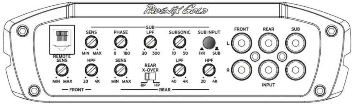
FRONT, REAR AND SUB INPUTS
Connect preamp signal cables from headunit to these inputs.
SUB INPUT SWITCH
Determines which input will feed signal to the subwoofer channel. "OUT" or SUB = Use the Sub Input
"IN" or F/R = Use the Front and Rear inputs as its signal will be summed then sent to the sub channel of the amplifier
Controls the crossover points for the speaker outputs.
REAR X-OVER CONFIG
HP: High pass crossover is on
BP: Low and high pass crossovers are both on, creating a Bandpass (BP) filter for midbass/midrange drivers. Check on page 4 (Ti2 1000.4) for more details on how to use the the BP setting for a fully active crossover system.
SENS
Used to reach maximum amplifier power with a wide variety of headunits.
REMOTE BASS LEVEL CONTROL (RBCF)
This port is for connecting the remote subwoofer level control. This allows up to 20dB of volume adjustment for the subwoofer channel. This is not a bass boost, it controls the level of the low pass signal.
PHASE
This allows the phase of the subwoofer output to be adjusted from 0 to 180 degrees. This adjustment can help achieve better "up front" subwoofer bass and resolve subwoofer cancellation problems in certain installations. Each installation is different, slowly adjust and listen for best results.
text_image
Rocky Gold SENS PHASE SUB LPF SUBSONIC SUB INPUT L FRONT REAR SUB MIN MAX 0 180 20 300 10 50 F/R SUB REMOTE SENS HPF SENS REAR X-OVER LPF HPF MIN MAX BP HP 40 4K 20 4K R INPUT — FRONT — — REAR —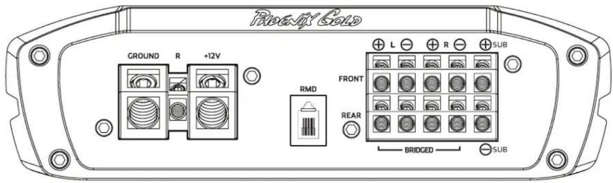
text_image
Rocky Gold GROUND R +12V RMD FRONT REAR L ⊕ ⊕ ⊕ ⊕ BRIDGED SUB ⊕ L ⊕ ⊕ ⊕ ⊕ ⊕ ⊕ ⊕ ⊕ ⊕ ⊕ ⊕ ⊕ ⊕ ⊕ ⊕ ⊕ ⊕ ⊕ ⊕ ⊕ ⊕ ⊕ ⊕ ⊕ ⊕ ⊕ ⊕ ⊕ ⊕ ⊕ ⊕ ⊕ ⊕ ⊕ ⊕ ⊕ ⊕ ⊕ ⊕ ⊕ ⊕ ⊕ ⊕ ⊕ ⊕ ⊕ ⊕ ⊕ ⊕ ⊕ ⊕ ⊕ ⊕ ⊕ ⊕ ⊞ ⊕ ⊕ ⊕ ⊕ ⊕ ⊕ ⊕ ⊕ ⊕ ⊕ ⊕ ⊕ ⊕ ⊕ ⊕ ⊕ ⊕ ⊕ ⊕ ⊕ ⊕ ⊕ ⊕ ⊕ ⊕ ⊕ ⊕ ⊕ ⊕ ⊕ ⊕ ⊕ ⊕ ⊕ ⊕ ⊕ ⊕ ⊕ ⊕ ⊕ ⊕ ⊕ ⊕ ⊕ ⊕ ⊕ ⊕ ⊕ ⊕ ⊌+12V
This must be connected to the fused positive terminal (+12V) of the car's battery. The fuse must be located within 18 inches of the battery.
REMOTE
This must be connected to switched +12V, usually a trigger wire coming from the head unit or ignition.
GROUND
This must be connected to the negative terminal of the car's battery or bolted to a clean, unpainted part of the chassis of the vehicle.
REMOTE MONITORING DISPLAY (RMD)
Connect optional RMD Voltage Display to this port.
SPEAKER OUTPUTS
Used to connect the amplifier to speakers. Ti2 1600.5's minimum impedance is 4 ohms bridged or 2 ohms stereo on front and rear channels. Use the Left + and Right - to bridge the channels. Minimum impedance is 2 ohms for the subwoofer channel and its not bridgeable.
CLIP INDICATORS (located on top of the amplifier)
Lights when the amplifier reaches near maximum output. Under heavy use the clip indicators should be flashing during the peaks of the music. The clip indicator should not stay lit for long periods of time (more than 1 or 2 seconds), if this is the case you need to reduce system volume or the SENS level of the amplifier.
T12 1000.4 CROSSOVER SETTINGS
All crossover frequency potentiometers have 41 detents or "clicks" so the end user can set the exact cross over frequency desired.
FRONT AND REAR CHANNELS
| clicks | FRONT HP(45~4kHz) | REAR HP(45~4kHz) | REAR HP(20~4kHz) | REAR LP(40~4kHz) |
| 1 | 49 | 43 22 36 | ||
| 2 49 44 22 36 | ||||
| 3 50 44 22 36 | ||||
| 4 50 44 22 36 | ||||
| 5 50 44 28 36 | ||||
| 6 51 45 24 37 | ||||
| 7 54 48 26 37 | ||||
| 8 57 51 28 37 | ||||
| 9 63 55 29 37 | ||||
| 10 68 61 31 44 | ||||
| 11 75 67 34 56 | ||||
| 12 83 83 37 65 | ||||
| 13 93 97 41 77 | ||||
| 14 105 112 47 92 | ||||
| 15 121 132 54 108 | ||||
| 16 143 162 62 131 | ||||
| 17 172 204 75 164 | ||||
| 18 215 274 93 202 | ||||
| 19 291 288 121 215 | ||||
| 20 313 306 128 232 | ||||
| 21 330 330 135 246 | ||||
| 22 350 364 146 266 | ||||
| 23 383 380 159 290 | ||||
| 24 409 411 171 316 | ||||
| 25 442 460 188 352 | ||||
| 26 494 508 209 398 | ||||
| 27 544 579 230 441 | ||||
| 28 624 671 267 524 | ||||
| 29 737 778 309 626 | ||||
| 30 887 1.0k 372 797 | ||||
| 31 1.0k 1.2k 472 1.1k | ||||
| 32 1.3k 1.3k 666 1.2k | ||||
| 33 1.5k 1.5k 738 1.4k | ||||
| 34 1.6k 1.7k 832 1.6k | ||||
| 35 1.9k 1.9k 974 1.8k | ||||
| 36 2.0k 2.2k 1.2k 2.1k | ||||
| 37 2.4k 2.7k 1.5k 2.7k | ||||
| 38 2.9k 3.0k 2.0k 3.3k | ||||
| 39 3.6k 3.6k 3.1k 4.0k | ||||
| 40 4.1k 3.7k 3.8k 4.1k | ||||
| 41 4.1k 3.7k 3.9k 4.1k |
All crossover frequency potentiometers have 41 detents or "clicks" so the end user can set the exact cross over frequency desired.
FRONT AND REAR CHANNELS
| clicks | FRONT HP(20~4kHz) | REAR HP(20~4kHz) | REAR LP(40~4kHz) |
| 1 | 23 | 24 34 | |
| 2 23 24 34 | |||
| 3 23 24 34 | |||
| 4 23 24 34 | |||
| 5 23 24 34 | |||
| 6 24 24 35 | |||
| 7 25 26 35 | |||
| 8 25 27 35 | |||
| 9 27 28 35 | |||
| 10 28 30 39 | |||
| 11 30 33 41 | |||
| 12 33 36 49 | |||
| 13 36 40 64 | |||
| 14 41 46 74 | |||
| 15 47 53 87 | |||
| 16 54 62 103 | |||
| 17 66 76 123 | |||
| 18 81 98 153 | |||
| 19 106 125 200 | |||
| 20 126 132 217 | |||
| 21 133 141 234 | |||
| 22 144 152 247 | |||
| 23 153 164 269 | |||
| 24 165 175 291 | |||
| 25 178 194 320 | |||
| 26 197 216 352 | |||
| 27 221 238 394 | |||
| 28 253 279 444 | |||
| 29 291 328 520 | |||
| 30 355 381 614 | |||
| 31 461 508 768 | |||
| 32 649 673 958 | |||
| 33 728 746 1.1k | |||
| 34 809 844 1.3k | |||
| 35 955 955 1.5k | |||
| 36 1.1k 1.2k 1.7k | |||
| 37 1.4k 1.5k 2.0k | |||
| 38 2.1k 2.0k 2.5k | |||
| 39 2.8k 2.8k 3.0k | |||
| 40 3.7k 3.7k 4.1k | |||
| 41 3.8k 3.7k 4.1k |
SUB CHANNEL
| clicks | SUBSONIC(10~50hz) | LP(30~300Hz) |
| 1 17 27 | ||
| 2 17 27 | ||
| 3 17 27 | ||
| 4 17 27 | ||
| 5 17 27 | ||
| 6 18 27 | ||
| 7 18 27 | ||
| 8 18 30 | ||
| 9 18 33 | ||
| 10 19 37 | ||
| 11 19 41 | ||
| 12 19 46 | ||
| 13 20 51 | ||
| 14 20 57 | ||
| 15 21 65 | ||
| 16 21 74 | ||
| 17 23 85 | ||
| 18 25 99 | ||
| 19 26 117 | ||
| 20 27 123 | ||
| 21 27 128 | ||
| 22 27 133 | ||
| 23 28 139 | ||
| 24 29 146 | ||
| 25 30 154 | ||
| 26 30 162 | ||
| 27 32 172 | ||
| 28 33 181 | ||
| 29 34 193 | ||
| 30 35 203 | ||
| 31 37 221 | ||
| 32 38 237 | ||
| 33 39 244 | ||
| 34 40 252 | ||
| 35 40 264 | ||
| 36 41 272 | ||
| 37 42 282 | ||
| 38 43 295 | ||
| 39 43 303 | ||
| 40 44 315 | ||
| 41 44 315 |
T12 1000.4
HP: El crossover high pass es "on"
LP/BP: El crossover low y high pass es "on"
text_image
Phoenix Gold FRONT REAR L SENS X-OVER FREQ MIN MAX HPF LPF 45 4K R INPUT HPF LPF 40 4K X-OVER SENS 20 4K HPF LP/BP MIN MAX FLAT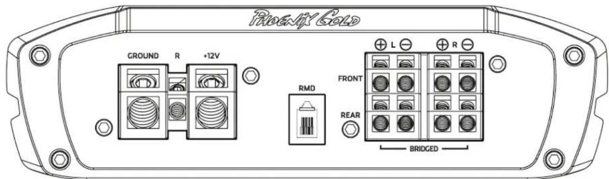
text_image
Phoenix Gold GROUND R +12V RMD FRONT REAR L R BRIDGED+12V
text_image
Phoenix Gold GROUND R +12V RMD FRONT REAR L ⊕ ⊕ ⊕ ⊕ BRIDGED ⊕ SUB+12V
text_image
Rexnly Gold GROUND R +12V RMD FRONT REAR L R BRIDGED+12V
text_image
Phoenix Gold GROUND R +12V RMD FRONT REAR L ⊕ ⊕ ⊕ ⊕ BRIDGED ⊕ SUB+12V
A Division of AAMP of America™
13190 56th Court
Clearwater, Florida 33760
P: 888-228-5560
info@phoenixgold.com
www.phoenixgold.com
© 2013 AAMP of Florida, Inc
Designed and Engineered in the USA
LIMITED WARRANTY ON AMPLIFIERS
Phoenix Gold warrants this product to be free of defects in materials and workmanship for a period of one (1) year from the original date of purchase. This warranty is not transferable and applies only to the original purchaser from an authorized Phoenix Gold dealer in the United States of America only. Should service be necessary under this warranty for any reason due to manufacturing defect or malfunction, Phoenix Gold will (at its discretion), repair or replace the defective product with new or remanufactured product at no charge. Damage caused by the following is not covered under warranty: accident, misuse, abuse, product modification or neglect, failure to follow installation instructions, unauthorized repair attempts, misrepresentations by the seller. This warranty does not cover incidental or consequential damages and does not cover the cost of removing or reinstalling the unit(s). Cosmetic damage due to accident or normal wear and tear is not covered under warranty.
INTERNATIONAL WARRANTIES:
Products purchased outside the United States of America are covered only by that country's Authorized Phoenix Gold reseller and not by Phoenix Gold. Consumers needing service or warranty information for these products must contact that country's reseller for information.