
DLS060WDB - Washing machine accessory DANBY - Free user manual and instructions
Find the device manual for free DLS060WDB DANBY in PDF.

| Product Type | Stacking kit for washing machine and dryer |
| Brand | Danby |
| Model | DLS060WDB |
| Use | Stack a dryer on top of a front-loading washing machine |
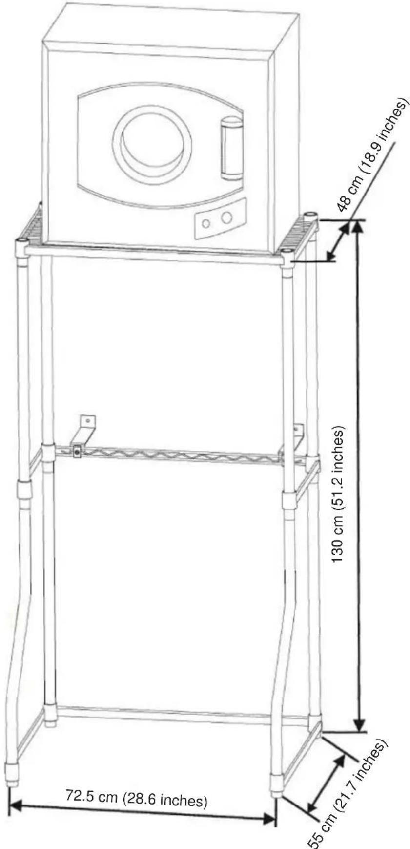
| Height | 130 cm (51.2 in) |
| Width | 72.5 cm (28.6 in) |
| Depth | 48 cm (18.9 in) |
| Materials | Painted steel and ABS plastic |
| Color | White |
| Compatibility | Front-loading washing machines and dryers |
| Wall mounting | Anti-tip bracket included, requires anchoring into a wall stud |
| Assembly | Requires manual assembly, tool included (wrench) |
| Package contents | 2 support frames, 1 top shelf, 4 front/rear feet (sections), 2 lower rear feet, 2 anti-tip brackets, 30 support clips, screws, anchors, wrench |
| Warranty | 1 year on functional parts, 30 days on plastic parts |
| Customer service | 1-800-263-2629 (Canada/USA) |
| Reference | DLS060WDB |
| Safety standards | Compliant with applicable safety standards |
| Care | Clean with a damp cloth and mild detergent |
Frequently Asked Questions - DLS060WDB DANBY
User questions about DLS060WDB DANBY
0 question about this device. Answer the ones you know or ask your own.
Ask a new question about this device
Download the instructions for your Washing machine accessory in PDF format for free! Find your manual DLS060WDB - DANBY and take your electronic device back in hand. On this page are published all the documents necessary for the use of your device. DLS060WDB by DANBY.
USER MANUAL DLS060WDB DANBY
Owner's Use and Care Guide....1 - 7
- Welcome
- Installation Instructions
- Troubleshooting
- Warranty
KIT D'EMBALLAGE DE LAVERIE
Welcome to the Danby family. We are proud of our quality products, and we believe in dependable service. We suggest that you read this Owner's Manual before plugging in your new appliance as it contains important operational information, safety information, troubleshooting and maintenance tips to ensure the reliability and longevity of your appliance. Visit www.Danby.com to access self-service tools, FAQs and much more. For additional assistance call 1-800-263-2629.
Note the information below; you will need this information to obtain service under warranty. To receive service, you must provide the original receipt.
Model Number:
Serial Number:
Date of Purchase:
NEED HELP?
Before you call for service, here are a few things you can do to help us serve you better:
Read this Owner's Use and Care Guide:
It contains instructions to help you use and maintain your appliance properly.
If you received a damaged appliance:
Immediately contact the retailer (or builder) that sold you the appliance.
Save time and money:
Check the Troubleshooting section at the end of the guide before calling. This section helps you solve common problems that may occur.
If you do need service, you can relax, knowing help is only a phone call away.

natural_image
Simple black-and-white icon of a telephone handset inside a circle (no text or symbols)1-800-26- Danby
(1-800-263-2629)
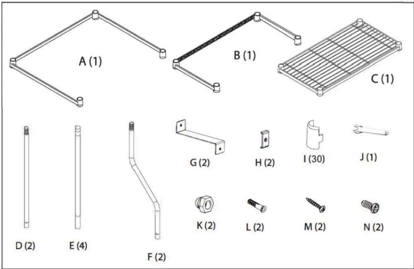
COMPONENTS
Before beginning to assemble the laundry stacking kit, ensure that you have all parts listed below.
| Part Code | Description Quantity | |
| A Bottom support frame 1 | ||
| B Middle support frame 1 | ||
| C Top shelf 1 | ||
| D Rear leg (bottom section) 2 | ||
| E Front / Rear leg (top section) 4 | ||
| F Front leg (bottom section) 2 | ||
| G Anti-Tip bracket (1 of 2) 2 | ||
| H Anti-Tip bracket (2 of 2) 2 | ||
| I Shelf / | Frame support clipsNote: 28 required for install, 2 extra pieces supplied as spares | 30 |
| J | Spanner wrench | 1 |
| K Nut (for Anti-Tip bracket assembly) | 2 | |
| L Wall anchor | 2 | |
| M | Phillips head self-tapping screw | 2 |
| N Phillips head metal screw (for Anti-Tip bracket assembly) | 2 | |
DIMENSIONS

Installation Instructions
ASSEMBLY
The laundry stacking kit is designed to accommodate both top loading or front loading washing machines. Please follow all assembly instructions below.
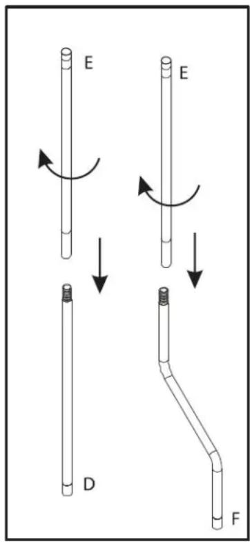
Step 1: Assembling the legs
Assemble the front legs by screwing together both sections of the front legs:
• Part E: Front / Rear leg (top section)
• Part F: Front leg (bottom section)
Assemble the rear legs by screwing together both sections of the rear legs:
• Part E: Front / Rear leg (top section)
• Part D: Rear leg (bottom section)
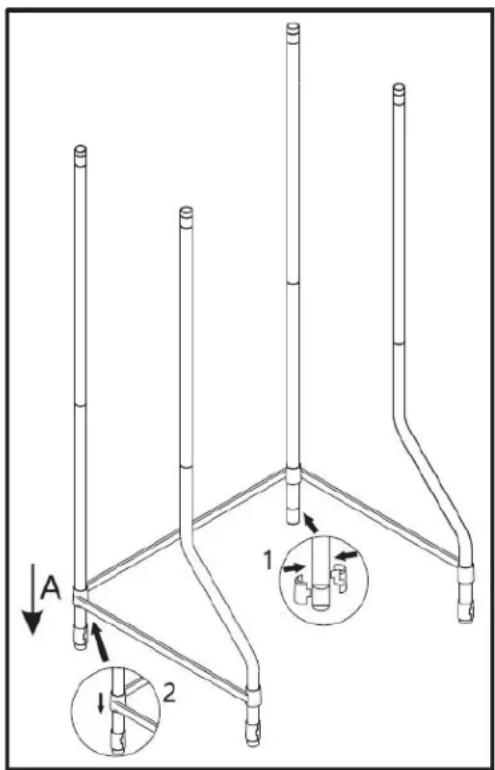
Step 2: Assembling the bottom support frame
- Lay Part A: bottom support frame on its back with each side bar facing upwards.
- Insert each of the rear legs into the holes at both rear corners of the support frame.
- Using Part I: shelf / frame support clips, insert the plastic tapered clips into the appropriate grooves on each back leg.
- Gently press the bottom support frame downward until it covers the support clips on the back legs. The support frame should click into place over the support clips.
- Insert each of the front legs into the remaining corner holes at the front of the support frame.
- Using Part I: shelf / frame support clips, insert the plastic tapered clips into the appropriate grooves on each front leg.
- Gently press the bottom support frame downward until it covers the support clips on the front legs. The support frame should click into place over the support clips.
- Place the stand upright and gently push down on each corner to ensure the support frame is fully locked into position.

Installation Instructions
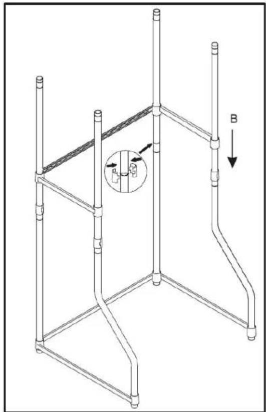
Step 3: Assembling the middle support frame
The middle support frame must be installed to maintain stability of the stacking kit.
- Using Part I: shelf / frame support clips, insert the plastic tapered clips into the appropriate grooves, just above the connection where the top and bottom sections of the legs screw together.
- Align the corner holes of Part B: middle support frame with the top of each leg and lower it into place over the support clips.
- Gently push down on each corner to ensure the support frame is fully locked into position.
Important note: If the support frames fall down and does not catch on the support clips correctly, ensure that the tapered edge of the support clip is pointing downward. If the support clips are installed upsidedown, the support frames will not click into place correctly.
natural_image
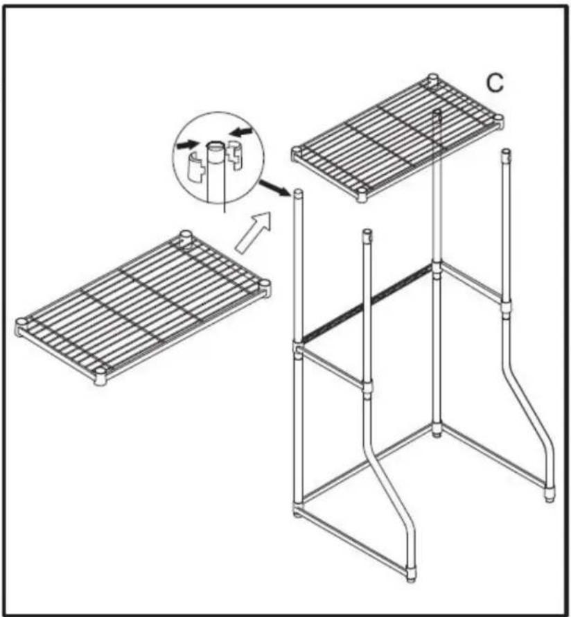
Technical line drawing of a structural frame with vertical supports and an inset showing a mechanical component (no text or symbols)Step 4: Assembling the top shelf
- Using Part I: shelf / frame support clips, insert the plastic tapered clips into the appropriate grooves at the top of each leg.
- Align the corner holes of Part C: top shelf with the top of each leg and lower it into place over the support clips.
- Gently push down on each corner to ensure the top shelf is fully locked into position.
Important note: If the stacking kit seems unstable or has a signifi cant wobble, ensure that the support frames are pushed down far enough to click over the support clips.

Installation Instructions
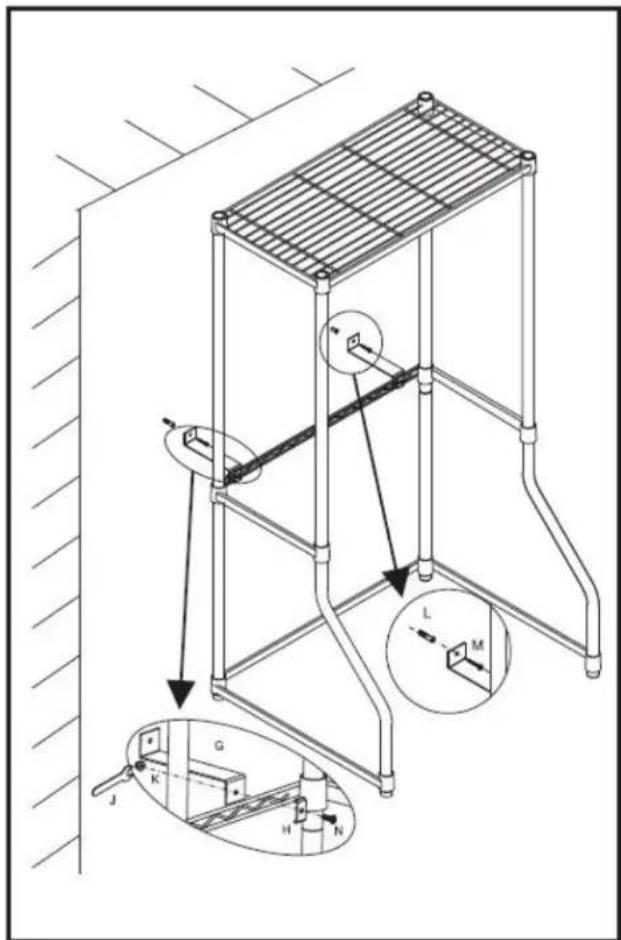
Step 5: Installing the Anti-Tip safety bracket
- Attach Part G: Anti-Tip bracket (1 of 2) and Part H: Anti-Tip bracket (2 of 2) around Part B: middle support frame as shown by joining the two parts using Part N: Phillips head metal screw and Part K: nut.
- Align the assembled stacking kit in place against the wall and mark where the Anti-Tip safety bracket needs to be secured to the wall.
- Use Part L: wall anchors and Part M: Phillips head self-tapping screw to secure the assembled stacking kit to the wall.
Important note: Ensure that screws align with a wall stud to ensure stacking kit stability.
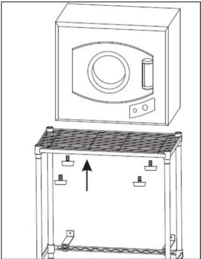
Step 6: Installing the dryer
- Remove the four levelling legs from the dryer.
- Place the dryer on the top shelf of the stacking kit.
- Re-install the four levelling legs through the underside of the top shelf and tighten until dryer is secured in place.
Important note: If the dryer seems unstable or if there is significant motion or noise from the dryer when it is in use, ensure that the levelling legs are tightened to minimize vibration and noise.
natural_image
Line drawing of a simple kitchen appliance with a top view and side view showing internal components (no text or symbols)LIMITED CARRY-IN APPLIANCE WARRANTY
This quality product is warranted to be free from manufacturer's defects in material and workmanship, provided that the unit is used under the normal operating conditions intended by the manufacturer.
This warranty is available only to the person to whom the unit was originally sold by Danby Products Limited (Canada) or Danby Products Inc. (U.S.A.) (hereafter "Danby") or by an authorized distributor of Danby, and is non-transferable.
TERMS OF WARRANTY
Plastic parts, are warranted for thirty (30) days only from purchase date, with no extensions provided.
| First 12 months | During the first twelve (12) months, any functional parts of this product found to be defective, will be repaired or replaced, at warrantor's option, at no charge to the ORIGINAL purchaser. |
| To obtain service | Danby reserves the right to limit the boundaries of “In Home Service” to the proximity of an Authorized Service Depot. Any appliance requiring service outside the limited boundaries of “In Home Service”, it will be the consumer's responsibility to transport the appliance (at their own expense) to the original retailer (point of purchase) or a service depot for repair. See “Boundaries of In Home Service” below. Contact your dealer from whom your unit was purchased, or contact your nearest authorized Danby service depot, where service must be performed by a qualified service technician. If service is performed on the units by anyone other than an authorized service depot, or the unit is used for commercial application, all obligations of Danby under this warranty shall be void. |
| Boundaries of in-home service | If the appliance is installed in a location that is 100 kilometers (62 miles) or more from the nearest service center your unit must be delivered to the nearest authorized Danby Service Depot, as service must only be performed by a technician qualified and certified for warranty service by Danby. Transportation charges to and from the service location are not protected by this warranty and are the responsibility of the purchaser. |
Nothing within this warranty shall imply that Danby will be responsible or liable for any spoilage or damage to food or other contents of this appliance, whether due to any defect of the appliance, or its use, whether proper or improper.
EXCLUSIONS
Save as herein provided, by Danby, there are no other warranties, conditions, representations or guarantees, express or implied, made or intended by Danby or its authorized distributors and all other warranties, conditions, representations or guarantees, including any warranties, conditions, representations or guarantees under any Sale of Goods Act or like legislation or statute is hereby expressly excluded. Save as herein provided, Danby shall not be responsible for any damages to persons or property, including the unit itself, howsoever caused or any consequential damages arising from the malfunction of the unit and by the purchase of the unit, the purchaser does hereby agree to indemnify and hold harmless Danby from any claim for damages to persons or property caused by the unit.
GENERAL PROVISIONS
No warranty or insurance herein contained or set out shall apply when damage or repair is caused by any of the following:
1) Power failure.
2) Damage in transit or when moving the appliance.
3) Improper power supply such as low voltage, defective house wiring or inadequate fuses.
4) Accident, alteration, abuse or misuse of the appliance such as inadequate air circulation in the room or abnormal operating conditions (extremely high or low room temperature).
5) Use for commercial or industrial purposes (ie. If the appliance is not installed in a domestic residence).
6) Fire, water damage, theft, war, riot, hostility, acts of God such as hurricanes, floods etc.
7) Service calls resulting in customer education.
8) Improper Installation (ie. Building-in of a free standing appliance or using an appliance outdoors that is not approved for outdoor application). Proof of purchase date will be required for warranty claims; so, please retain bills of sale. In the event warranty service is required, present this document to our AUTHORIZED SERVICE DEPOT.
Warranty Service
Carry-In
Danby Products Limited
PO Box 1778, Guelph, Ontario, Canada N1H 6Z9
Telephone: (519) 837-0920 FAX: (519) 837-0449
1-800-263-2629
07/14
Danby Products Inc.
PO Box 669, Findlay, Ohio, U.S.A. 45840
Telephone: (419) 425-8627 FAX: (419) 425-8629
Bienvenue
natural_image
Simple black-and-white icon of a telephone handset inside a circle (no text or symbols)1-800-26- Danby
(1-800-263-2629)
COMPOSANTS

natural_image
Technical line drawing of a structural frame with vertical supports and an inset showing a mechanical component (no text or symbols)
natural_image
Line drawing of a simple kitchen sink with a top panel and a side view showing internal components (no text or symbols)GARANTIE LIMITÉE SUR APPAREIL ÉLECTROMÉNAGER
Danby Products Limited
PO Box 1778, Guelph, Ontario, Canada N1H 6Z9
All repair parts are available for purchase or special order when you visit your nearest service depot. To request service and/or the location of the service depot nearest you, call the TOLL FREE number.
When requesting service or ordering parts, always provide the following information:
- Product Type
- Model Number
- Part Number
- Part Description
natural_image
Simple black-and-white icon of a telephone handset inside a circle (no text or symbols)1-800-26- Danby
(1-800-263-2629)
MODEL • MODÈLE
DLS060WDB
- Owner's Use and Care Guide....1 - 7
- KIT D'EMBALLAGE DE LAVERIE
- NEED HELP?
- Read this Owner's Use and Care Guide:
- If you received a damaged appliance:
- Save time and money:
- COMPONENTS
- DIMENSIONS
- Installation Instructions
- ASSEMBLY
- Step 1: Assembling the legs
- Step 2: Assembling the bottom support frame
- Step 3: Assembling the middle support frame
- Step 4: Assembling the top shelf
- Step 5: Installing the Anti-Tip safety bracket
- Step 6: Installing the dryer
- LIMITED CARRY-IN APPLIANCE WARRANTY
- TERMS OF WARRANTY
- EXCLUSIONS
- GENERAL PROVISIONS
- Warranty Service
- Carry-In
- Bienvenue
- COMPOSANTS
- GARANTIE LIMITÉE SUR APPAREIL ÉLECTROMÉNAGER
Brand : DANBY
Model : DLS060WDB
Category : Washing machine accessory