
AG 24-230 E - Grinder MILWAUKEE - Free user manual and instructions
Find the device manual for free AG 24-230 E MILWAUKEE in PDF.

| Brand | Milwaukee |
| Model | AG 24-230 E |
| Product type | Grinder (angle grinder) |
| Nominal power | 2400 W |
| Nominal speed | 6600 min⁻¹ |
| Max. grinding wheel diameter | 230 mm |
| Grinding wheel bore | 22.2 mm |
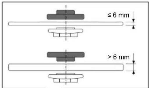
| Max. polishing disc thickness | 6 mm |
| Cutting disc thickness | 1.9 to 3 mm |
| Max. wire brush diameter | 100 mm |
| Shaft thread | M14 |
| Weight (according to EPTA 01/2014) | 5.3 kg |
| Sound pressure level (LpA) | 93 dB(A) (uncertainty K=3 dB) |
| Sound power level (LWA) | 104 dB(A) (uncertainty K=3 dB) |
| Vibration - Rough grinding (a_h,SG) | 6.0 m/s² (K=1.5 m/s²) |
| Vibration - Sanding with emery cloth (a_h,DS) | < 2.5 m/s² (K=1.5 m/s²) |
| Restart protection | Yes |
| Start-up current limitation | Yes |
| Soft start | Yes (electronic) |
| Main applications | Grinding, cutting, sanding, wire brushing |
| Power supply | Single-phase, 230 V ~ |
| Protection class | II (double insulation) |
| Maintenance | Clean ventilation openings regularly; replace damaged cable with a Milwaukee cable |
| Safety | Always wear safety glasses, hearing protection and gloves |
| Spare parts | Use only Milwaukee parts; contact authorized service center |
Frequently Asked Questions - AG 24-230 E MILWAUKEE
User questions about AG 24-230 E MILWAUKEE
0 question about this device. Answer the ones you know or ask your own.
Ask a new question about this device
Download the instructions for your Grinder in PDF format for free! Find your manual AG 24-230 E - MILWAUKEE and take your electronic device back in hand. On this page are published all the documents necessary for the use of your device. AG 24-230 E by MILWAUKEE.
USER MANUAL AG 24-230 E MILWAUKEE
natural_image
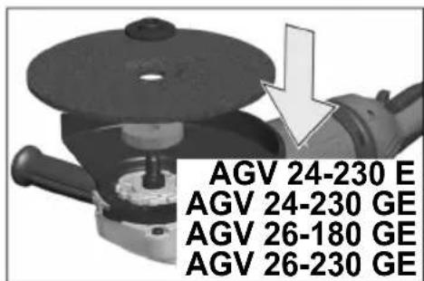
Exterior view of a Milwaukee electric power tool (no text or symbols on the device body)AG 24-230 E
AGV 24-230 E
AGV 24-230 GE
AGV 26-230 GE
Original instructions
natural_image
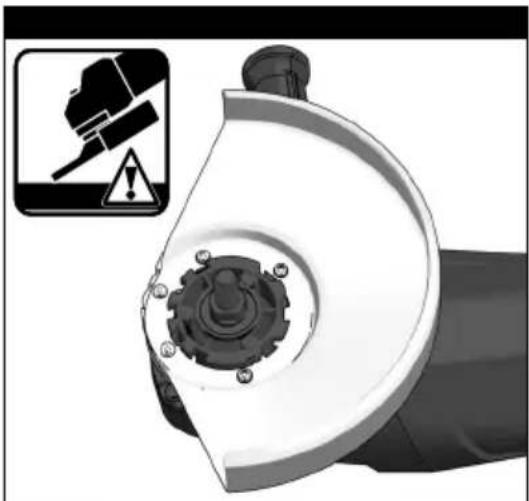
Close-up of a mechanical power tool with a circular base and textured surface (no visible text or symbols)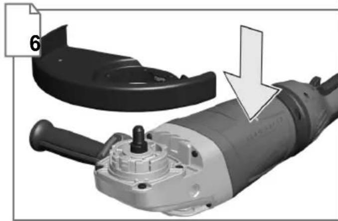
natural_image
Close-up of a mechanical power tool with a labeled part (6) and an arrow indicating a process or operation (no text or symbols on the tool itself)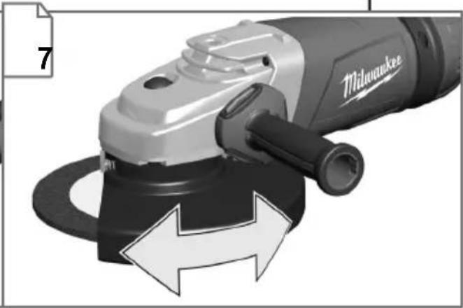
natural_image
Close-up of a Milwaukee angle grinder with directional arrows indicating rotation (no text or symbols on the device itself)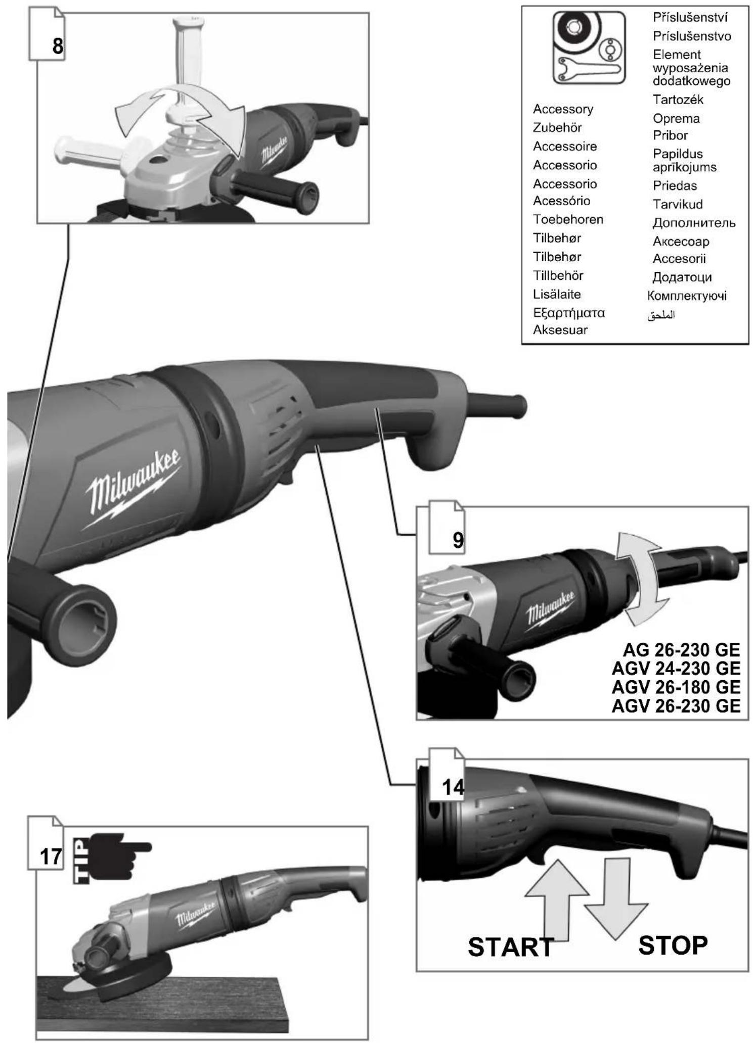
Accessory
Zubehör
Accessoire
Accessorio
Accessorio
Acessório
Toebehoren
Tilbehør
Tilbehør
Tillbehör
Lisälaite
Εξαρτήματα
Aksesuar
Příslušenství
Príslušenstvo
Element
natural_image
Close-up of a mechanical power tool with a curved blade and a downward arrow indicating a cut or dissection (no text or symbols visible)

natural_image
Close-up of a mechanical device with a gear and mounting base, accompanied by a warning icon (no text or symbols on the device itself)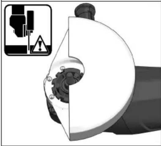
natural_image
Mechanical component with gear and mounting bracket, shown in 3D rendering (no text or symbols)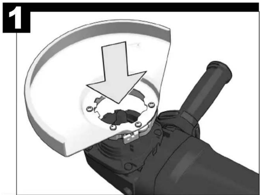
natural_image
Close-up of a mechanical device with a downward arrow indicating a cut or dissection (no text or symbols visible)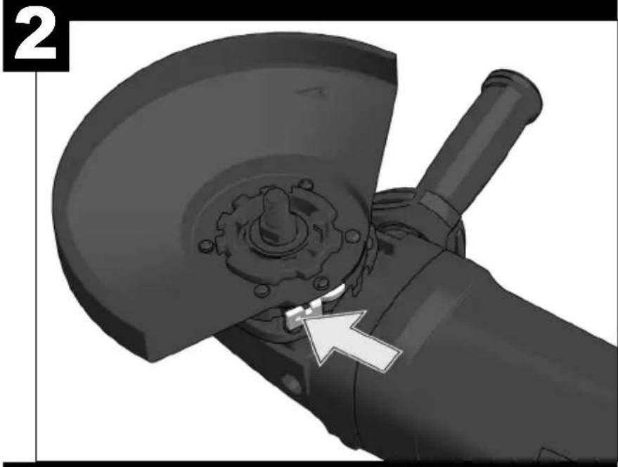
natural_image
Close-up of a mechanical grinding tool with a circular cutter and central hub, showing no text or symbols.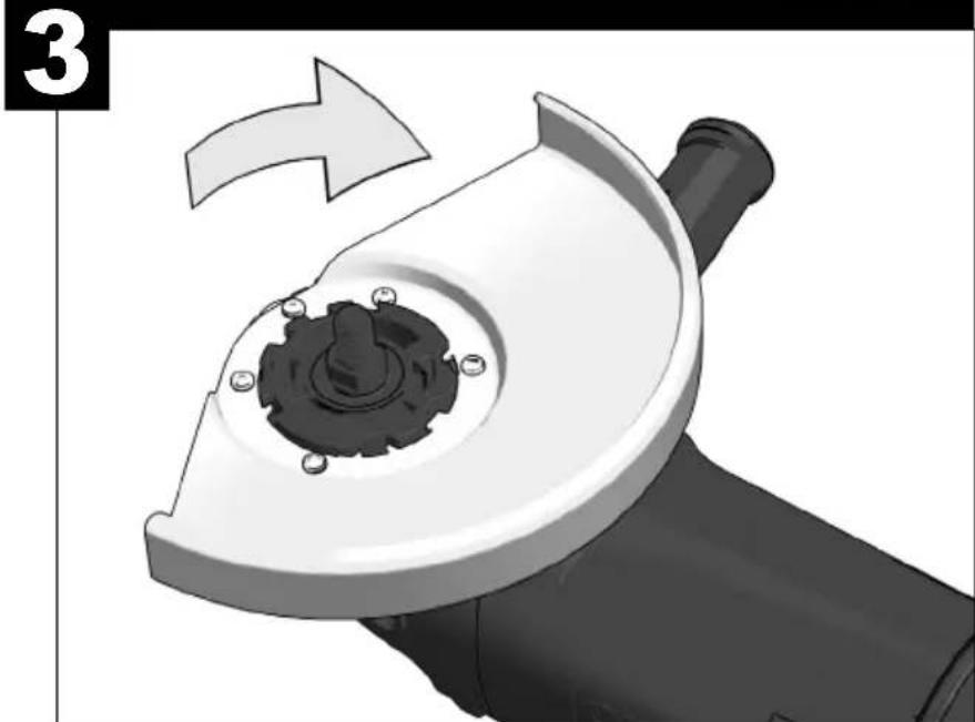
natural_image
Close-up of a mechanical tool with a gear and blade assembly, showing a curved arrow indicating rotation (no text or symbols)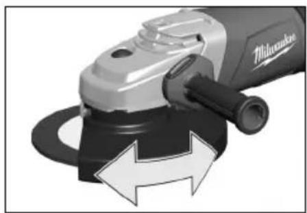
natural_image
Close-up of a Milwaukee electric grinder with directional arrows indicating motion (no text or symbols on the device itself)

1
natural_image
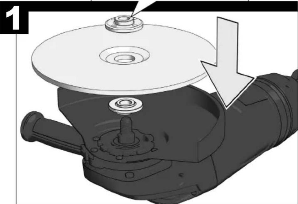
Mechanical component with a circular base and mounting holes, showing a directional arrow (no text or symbols)2
natural_image
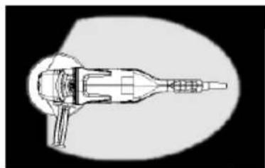
Cross-sectional diagram of a mechanical device with no visible text or symbols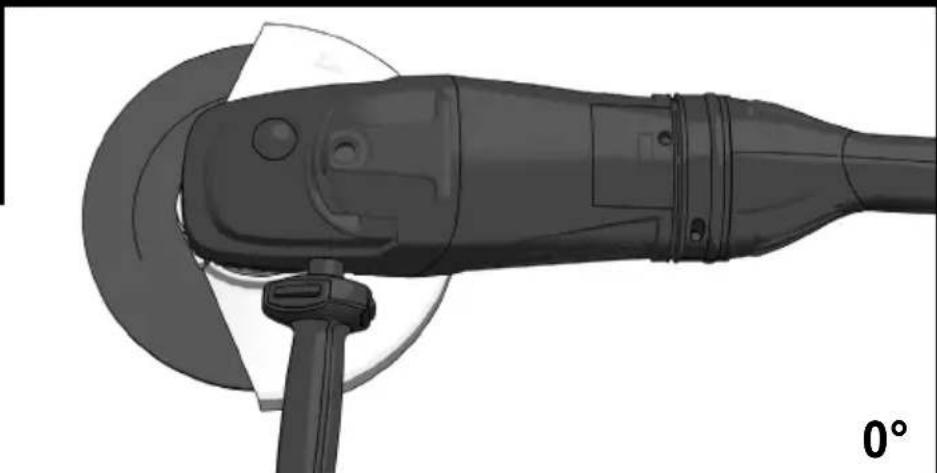
natural_image
Technical illustration of a mechanical power tool with a 0° angle indicator (no text or symbols on the tool itself)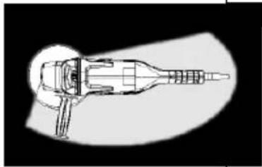
natural_image
Technical line drawing of a mechanical device with no visible text or symbols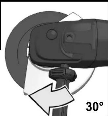
natural_image
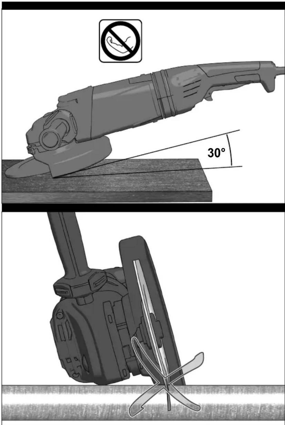
Close-up of a mechanical power tool with a 30° angle indicator (no text or symbols on the tool itself)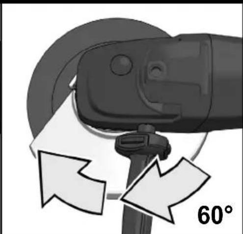
natural_image
Close-up of a mechanical device with angular arrows indicating motion, no visible text or symbols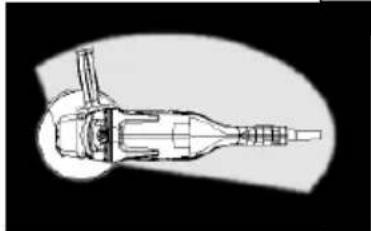
natural_image
Technical line drawing of a mechanical component with no visible text or symbols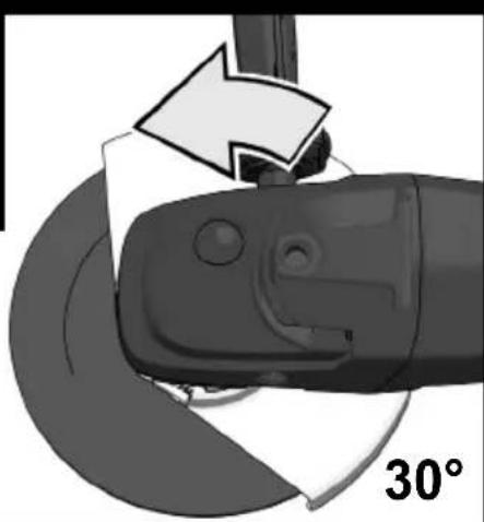
natural_image
Close-up of a mechanical tool with a 30° angle indicator and arrow, no readable text or symbols beyond the angle label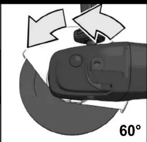
natural_image
Close-up of a robotic hand gripping a circular object with directional arrows indicating rotation (no text or symbols)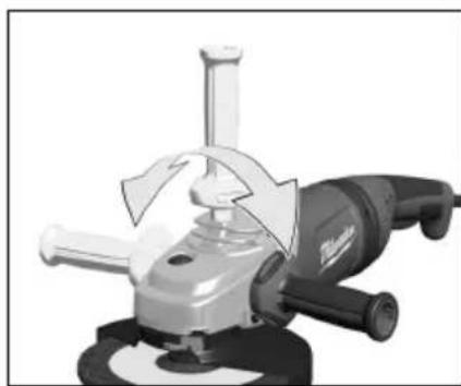
natural_image
Close-up of a mechanical power tool with a blade and handle, no visible text or symbols

1
natural_image
Illustration of a power tool with a magnifying glass and mechanical component, showing no text or symbols2
natural_image
Illustration of a power tool with a screw and handle, showing mechanical components and downward arrows indicating motion (no text or symbols)3
natural_image
Illustration of a power tool with a hammer and screwdriver, showing mechanical components and a directional arrow (no text or symbols)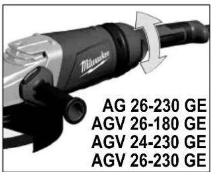


natural_image
Illustration of a black electric vehicle charging plug with a white arrow pointing to the plug (no text or symbols)
natural_image
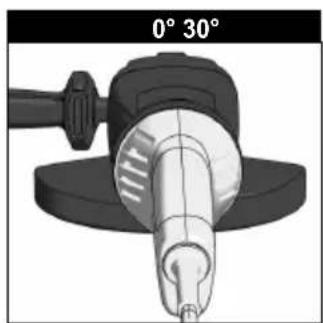
3D rendered mechanical component with angular measurement indicators (0° and 30°) shown above, no readable text or symbols on the object itself.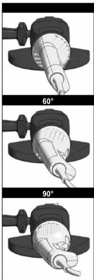
natural_image
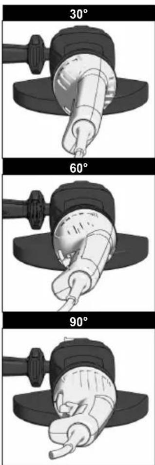
Three sequential images showing a power tool being handled, with 60° and 90° angle labels (no text or symbols on the tools themselves)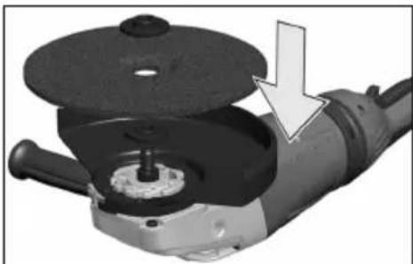
natural_image
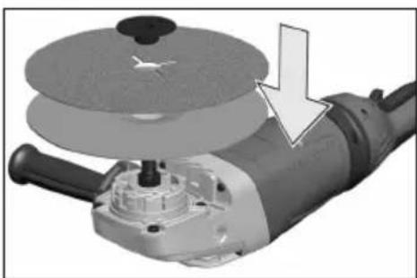
Close-up of a mechanical power tool with a circular disc and base, showing a downward arrow indicating a component (no text or symbols visible)AG 24-230 E AG 26-230 GE
Use only spindle nuts as provided by the manufacturer. Do not use any keyless nuts!
natural_image
Mechanical assembly diagram showing a rotating component with a central hub and a circular plate (no text or symbols)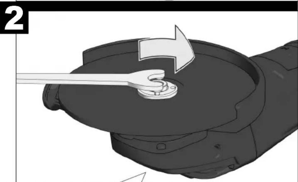
natural_image
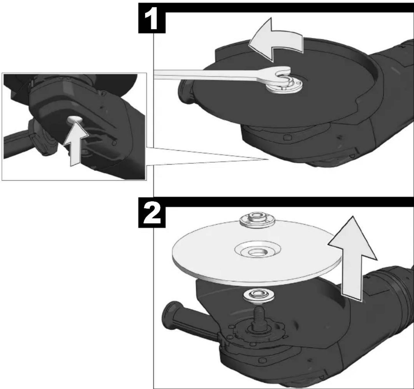
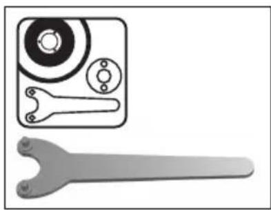
Illustration of a mechanical component with a wrench and arrow indicating motion (no text or symbols)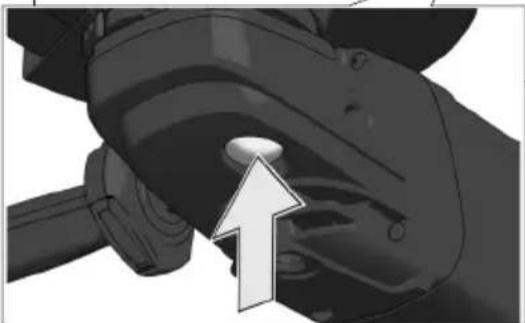
natural_image
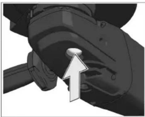
Close-up of a mechanical component with a white arrow pointing to a knob (no text or symbols visible)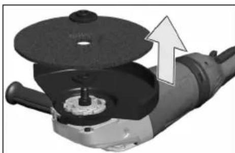
natural_image
Close-up of a mechanical power tool with a circular component and an upward arrow indicating motion (no text or symbols)AG 24-230 E AG 26-230 GE


natural_image
Mechanical assembly diagram showing a rotating disc and shaft assembly with a downward arrow indicating motion (no text or symbols)Use only spindle nuts as provided by the manufacturer. Do not use any keyless nuts!
natural_image
3D mechanical component diagram showing a tool interacting with a central hub, no text or symbols present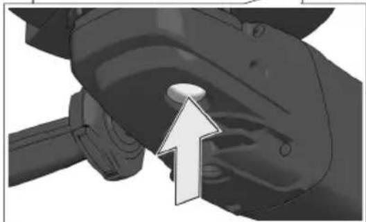
natural_image
Close-up of a mechanical component with a white arrow pointing to a circular feature (no text or symbols visible)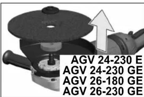

natural_image
Close-up of a mechanical component with a white arrow pointing upward, no visible text or symbolsnatural_image
3D illustration of a mechanical component with a wrench inserted, showing a tool interacting with a central hole (no text or symbols)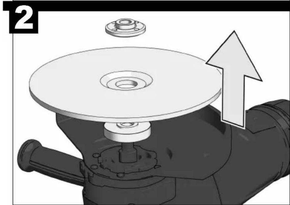
natural_image
Mechanical assembly diagram showing a rotating disc mounted on a base with a flange and bolt, accompanied by an upward arrow indicating motion (no text or symbols present)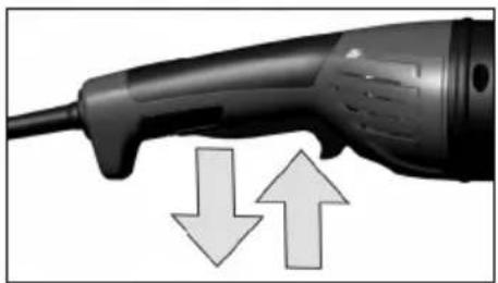
natural_image
Close-up of a black electric shocker with two downward arrows and an upward arrow indicating compression or movement (no text or symbols)


Techtronic Industries GmbH Max-Eyth-Straße 10 - 71364 Winnenden-Germany
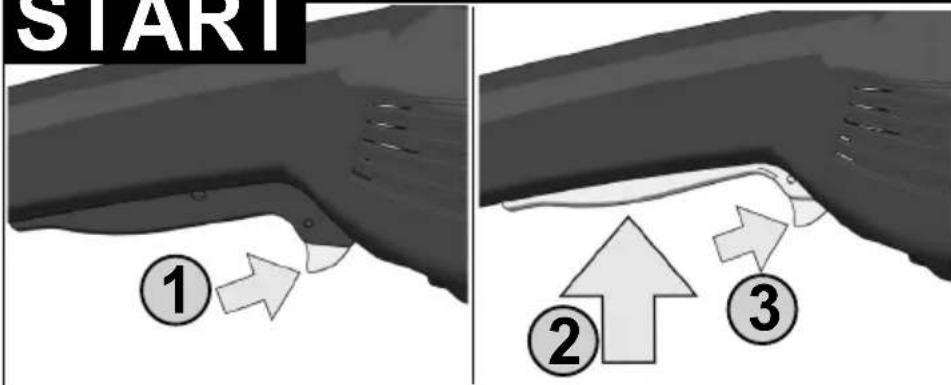
Switch can be locked
natural_image
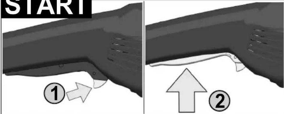
Illustration of a medical device with an eye symbol and a close-up inset showing the eye (no text or symbols present)START
natural_image
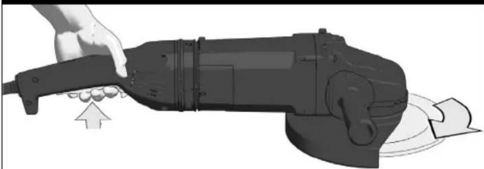
Illustration of a hand using a power tool to lift a motor, showing motion and rotation (no text or symbols)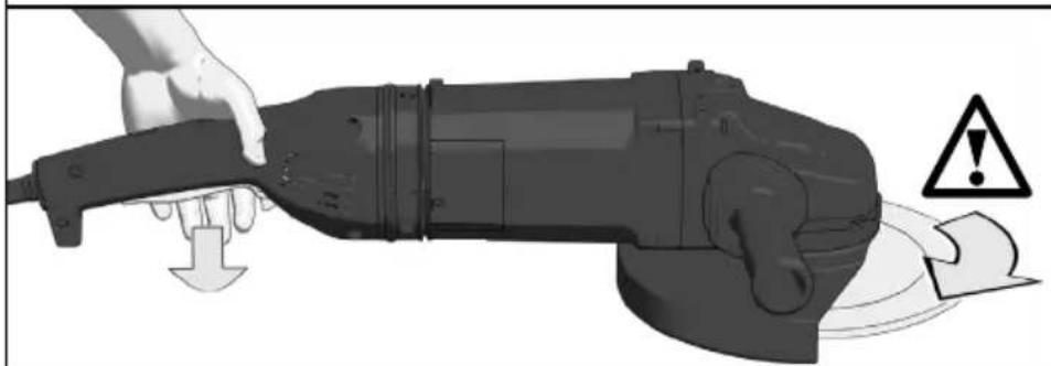
natural_image
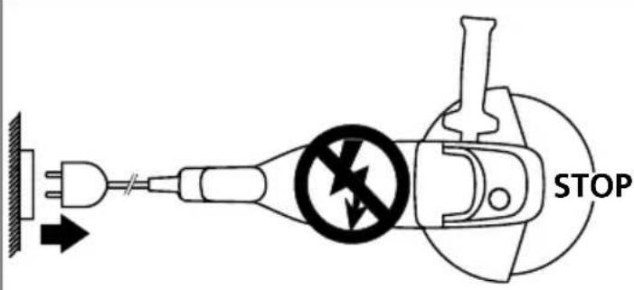
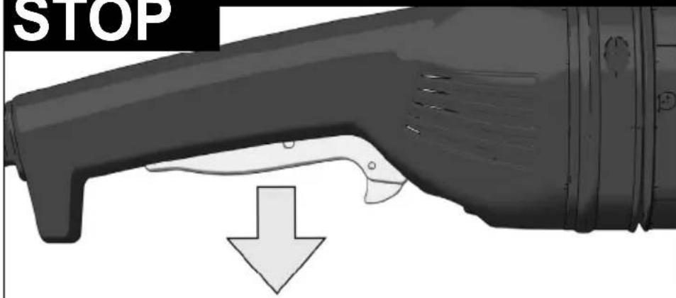
Illustration of a hand using a power tool to press down a mechanical component, with warning symbols (no text or labels)STOP
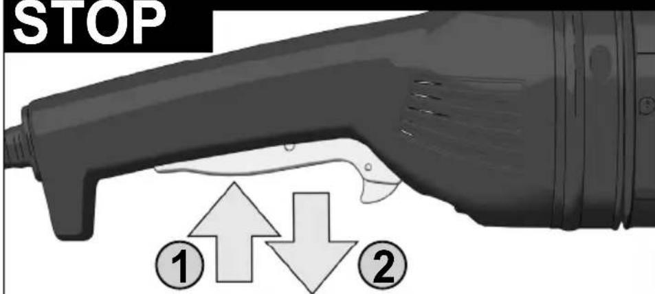
Startup protection:
When switched on, the machine will not start up after voltage breakdown. To continue working, switch the machine off and then on again.
Wiederanlaufschutz:
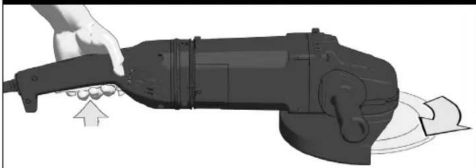
Switch cannot be locked
natural_image
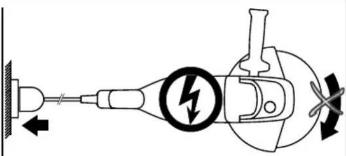
Technical illustration of a mechanical component with a tool inserted, showing no text or symbols on the main body.START
STOP
natural_image
Illustration of a hand using a power tool to lift a motor, showing motion and rotation (no text or symbols)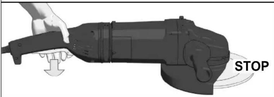


natural_image
Close-up of a mechanical power tool with a disc and blade assembly, showing no visible text or symbols.


natural_image
Illustration of a wrench and its corresponding mechanical component (no text or symbols)Use only spindle nuts as provided by the manufacturer. Do not use any keyless nuts!
natural_image
3D illustration of a mechanical device with a spool and base mount, showing internal components (no text or symbols)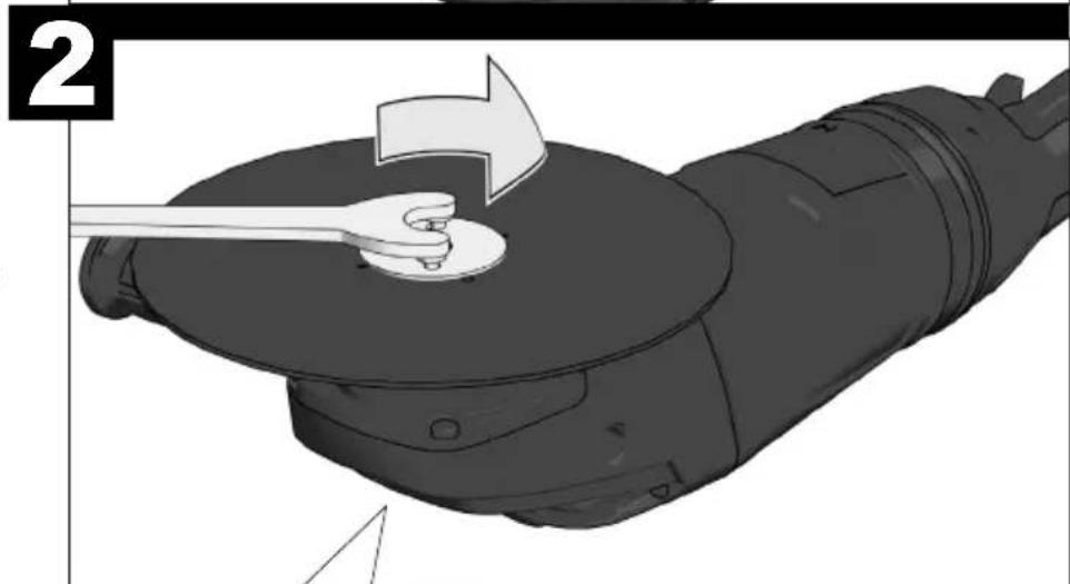
natural_image
Illustration of a hand using a wrench to lift a circular component, no text or symbols present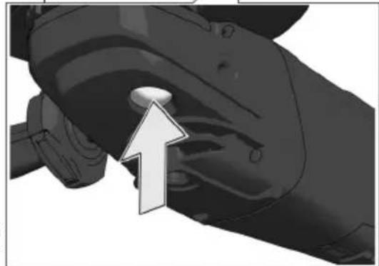
natural_image
Close-up of a hand gripping a mechanical component with an arrow pointing to the center (no text or symbols visible)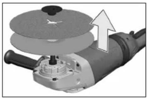
natural_image
Close-up of a mechanical power tool with a circular disc and an arrow indicating motion (no text or symbols)


natural_image
Illustration of a wrench tool and its corresponding mechanical component (no text or symbols)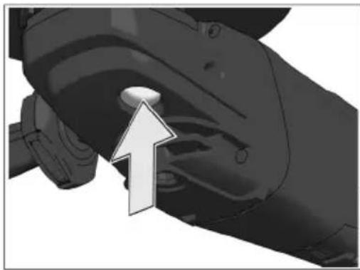
natural_image
Close-up of a mechanical component with an arrow pointing to a circular feature (no text or symbols visible)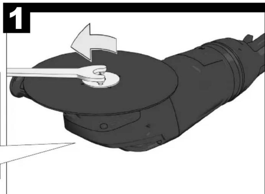
natural_image
Illustration of a hand using a wrench to press or install a mechanical component, no text or symbols present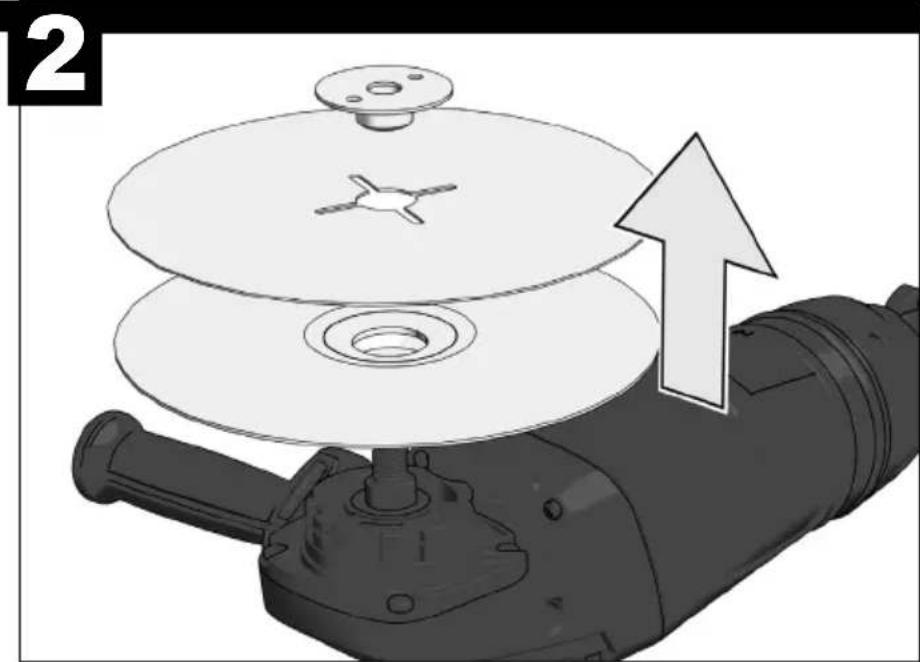
natural_image
3D illustration of a mechanical device with a fan and base plate, showing an upward arrow indicating motion (no text or symbols)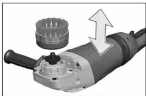
natural_image
Close-up of a mechanical power tool with a gear and directional arrow indicating motion (no text or symbols)


Accessory
Zubehör
Accessoire
Accessorio
Accessorio
Acessório
Toebehoren
Tilbehør
Tilbehør
Tillbehör
Lisälaite
Εξαρτήματα
Aksesuar
Příslušenství
Príslušenstvo
Element
wyposażenia
dodatkowego
Tartozék
Oprema
Pribor
Papildus
aprikojums
Priedas
Tarvikud
Дополнитель
Аксесоар
Accesorii
Додатоци
Комплектуючі
الملحق
| TECHNICAL DATA AG 24-230E AGV 24-230E AGV 26-230 GEAngle Grinder AGV 24-230 GE | |||
| Production code 4026 15 04... | 4026 57 04...4768 20 02...4768 35 02......000001-999999 | 4026 21 04...4026 18 04...4026 69 04...4768 48 02...4768 59 02...4768 98 02......000001-999999 | 4026 53 04...4026 65 04...4769 08 02...4769 10 02......000001-999999 |
| Rated input 2400 W 2400 W 2600 W | |||
| Rated speed 6600 min | -1 | 6600 min^-1 | 6600 min^-1 |
D=Grinding disk diameter max.d=Grinding disk hole diameter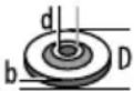 b=Grinding disk thickness max.. 6 mm (1/4") 6mm (1/4") 6 mm (1/4") b=Grinding disk thickness max.. 6 mm (1/4") 6mm (1/4") 6 mm (1/4")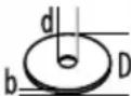 b=Cutting disk thickness min. / max. b=Cutting disk thickness min. / max. | 230 mm22,2 mm | 230 mm22,2 mm | 230 mm22,2 mm |
| 1,9 / 3 mm 1,9 / 3 mm 1,9 / 3 mm | |||
 D=Grinding surface diameter max. D=Grinding surface diameter max. | 230 mm 230 mm 230 mm | ||
| [DYTH] D=Wiring brush diameter max. 100 mm 100 mm 100 mm | |||
| Thread of work spindle M14 M14 | M14 | ||
| Weight according EPTA-Procedure 01/2014 5,3 kg | 5,5 kg | 5,5 kg | |
| Noise/Vibration InformationMeasured values determined according to EN 60 745.Typically, the A-weighted noise levels of the tool are:Sound pressure level (Uncertainty K=3dB(A))Sound power level(Uncertainty K=3dB(A))Wear ear protectors!Vibration total values (triaxial vector sum) determinedaccording to EN 60745.Surface grinding:Vibration emission value a_h,SG Uncertainty K SandingVibration emission value a_h,DS Uncertainty K For other applications, e.g. Abrasive Cutting-Off Operations or Wire Brushing other vibration values could occur. | |||
WARNING
The vibration emission level given in this information sheet has been measured in accordance with a standardised test given in EN 60745 and may be used to compare one tool with another. It may be used for a preliminary assessment of exposure.
The declared vibration emission level represents the main applications of the tool. However if the tool is used for different applications, with different accessories or poorly maintained, the vibration emission may differ. This may significantly increase the exposure level over the total working period.
An estimation of the level of exposure to vibration should also take into account the times when the tool is switched off or when it is running but not actually doing the job. This may significantly reduce the exposure level over the total working period.
Identify additional safety measures to protect the operator from the effects of vibration such as: maintain the tool and the accessories, keep the hands warm, organisation of work patterns
WARNING! Read all safety warnings and all instructions. Failure to follow the warnings and instructions may result in electric shock, fi re and/or serious injury. Save all warnings and instructions for future reference.
ANGLE GRINDER SAFETY WARNINGS
Safety Warnings Common for Grinding, Sanding, Wire Brushing or Abrasive Cutting-Off Operations:
a) This power tool is intended to function as a grinder, sander, wire brush, or cut-off tool. Read all safety warnings, instructions, illustrations and specifications provided with this power tool. Failure to follow all instructions listed below may result in electric shock, fire and/or serious injury.
b) Operations as polishing are not recommended to be performed with this power tool. Operations for which the power tool was not designed may create a hazard and cause personal injury.
c) Do not use accessories which are not specifically designed and recommended by the tool manufacturer. Just because the accessory can be attached to your power tool, it does not assure safe operation.
d) The rated speed of the accessory must be at least equal to the maximum speed marked on the power tool. Accessories running faster than their rated speed can break and fly apart.
e) The outside diameter and the thickness of your accessory must be within the capacity rating of your power tool. Incorrectly sized accessories cannot be adequately guarded or controlled.
f) The arbour size of wheels, fl anges, backing pads or any other accessory must properly fi t the spindle of the power tool. Accessories with arbour holes that do not match the mounting hardware of the power tool will run out of balance, vibrate excessively and may cause loss of control.
g) Do not use a damaged accessory. Before each use inspect the accessory such as abrasive wheels for chips and cracks, backing pad for cracks, tear or excess wear, wire brush for loose or cracked wires. If power tool or accessory is dropped, inspect for damage or install an undamaged accessory. After inspecting and installing an accessory, position yourself and bystanders away from the plane of the rotating accessory and run the power tool at maximum no-load speed for one minute. Damaged accessories will normally break apart during this test time.
h) Wear personal protective equipment. Depending on application, use face shield, safety goggles or safety glasses. As appropriate, wear dust mask, hearing protectors, gloves and shop apron capable of stopping small abrasive or workpiece fragments. The eye protection must be capable of stopping fl ying debris generated by various operations. The dust mask or respirator must be capable of fl ltrating particles generated by your operation. Prolonged exposure to high intensity noise may cause hearing loss.
i) Keep bystanders a safe distance away from work area. Anyone entering the work area must wear personal protective equipment. Fragments of workpiece or of a broken accessory may fly away and cause injury beyond immediate area of operation.
j) Hold power tool by insulated gripping surfaces only, when performing an operation where the cutting tool may contact hidden wiring or its own cord. Cutting accessory contacting a "live" wire may make exposed metal parts of the power tool "live" and could give the operator an electric shock.
k) Position the cord clear of the spinning accessory. If you lose control, the cord may be cut or snagged and your hand or arm may be pulled into the spinning accessory.
I) Never lay the power tool down until the accessory has come to a complete stop. The spinning accessory may grab the surface and pull the power tool out of your control.
m) Do not run the power tool while carrying it at your side. Accidental contact with the spinning accessory could snag your clothing, pulling the accessory into your body.
n) Regularly clean the power tool's air vents. The motor's fan will draw the dust inside the housing and excessive accumulation of powdered metal may cause electrical hazards.
o) Do not operate the power tool near fl ammable materials. Sparks could ignite these materials.
p) Do not use accessories that require liquid coolants. Using water or other liquid coolants may result in electrocution or shock.
Kickback and Related Warnings
Kickback is a sudden reaction to a pinched or snagged rotating wheel, backing pad, brush or any other accessory. Pinching or snagging causes rapid stalling of the rotating accessory which in turn causes the uncontrolled power tool to be forced in the direction opposite of the accessory's rotation at the point of the binding.
For example, if an abrasive wheel is snagged or pinched by the workpiece, the edge of the wheel that is entering into the pinch point can dig into the surface of the material causing the wheel to climb out or kick out. The wheel may either jump toward or away from the operator, depending on direction of the wheel's movement at the point of pinching. Abrasive wheels may also break under these conditions.
Kickback is the result of power tool misuse and/or incorrect operating procedures or conditions and can be avoided by taking proper precautions as given below.
a) Maintain a fi rm grip on the power tool and position your body and arm to allow you to resist kickback forces. Always use auxiliary handle, if provided, for maximum control over kickback or torque reaction during start-up. The operator can control torque reactions or kickback forces, if proper precautions are taken.
b) Never place your hand near the rotating accessory. Accessory may kickback over your hand.
c) Do not position your body in the area where power tool will move if kickback occurs. Kickback will propel the tool in direction opposite to the wheel's movement at the point of snagging.
d) Use special care when working corners, sharp edges etc. Avoid bouncing and snagging the accessory.
Corners, sharp edges or bouncing have a tendency to snag the rotating accessory and cause loss of control or kickback
e) Do not attach a saw chain, woodcarving blade or toothed saw blade. Such blades create frequent kickback and loss of control.
Safety Warnings Specific for Grinding and Abrasive Cutting-Off Operations:
a) Use only wheel types that are recommended for your power tool and the specific guard designed for the selected wheel. Wheels for which the power tool was not designed cannot be adequately guarded and are unsafe.
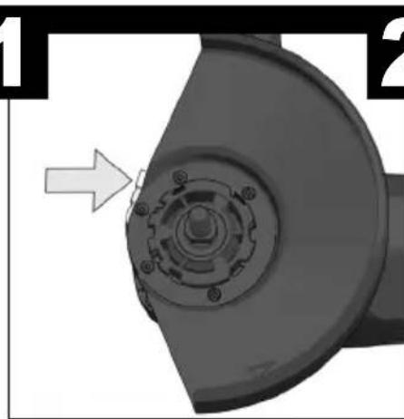
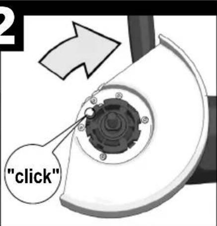
b) The guard must be securely attached to the power tool and positioned for maximum safety, so the least amount of wheel is exposed towards the operator. The guard helps to protect operator from broken wheel fragments and accidental contact with wheel and sparks that could ignite clothing.
c) Wheels must be used only for recommended applications. For example: do not grind with the side of cut-off wheel. Abrasive cut-off wheels are intended for peripheral grinding, side forces applied to these wheels may cause them to shatter.
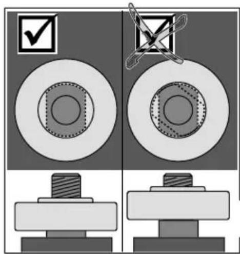
d) Always use undamaged wheel fl anges that are of correct size and shape for your selected wheel. Proper wheel fl anges support the wheel thus reducing the possibility of wheel breakage. Flanges for cut-off wheels may be different from grinding wheel flanges.
e) Do not use worn down wheels from larger power tools. Wheel intended for larger power tool is not suitable for the higher speed of a smaller tool and may burst.
Additional Safety Warnings Specific for Abrasive Cutting-Off Operations:
a) Do not "jam" the cut-off wheel or apply excessive pressure. Do not attempt to make an excessive depth of cut. Overstressing the wheel increases the loading and susceptibility to twisting or binding of the wheel in the cut and the possibility of kickback or wheel breakage.
b) Do not position your body in line with and behind the rotating wheel. When the wheel, at the point of operation, is moving away from your body, the possible kickback may propel the spinning wheel and the power tool directly at you.
c) When wheel is binding or when interrupting a cut for any reason, switch off the power tool and hold the power tool motionless until the wheel comes to a complete stop. Never attempt to remove the cut-off wheel from the cut while the wheel is in motion otherwise kickback may occur. Investigate and take corrective action to eliminate the cause of wheel binding.
d) Do not restart the cutting operation in the workpiece. Let the wheel reach full speed and carefully re-enter the cut. The wheel may bind, walk up or kickback if the power tool is restarted in the workpiece.
e) Support panels or any oversized workpiece to minimize the risk of wheel pinching and kickback. Large workpieces tend to sag under their own weight. Supports must be placed under the workpiece near the line of cut and near the edge of the workpiece on both sides of the wheel.
f) Use extra caution when making a "pocket cut" into existing walls or other blind areas. The protruding wheel may cut gas or water pipes, electrical wiring or objects that can cause kickback.
Safety Warnings Specific for Sanding Operations:
a) Do not use excessively oversized sanding disc paper. Follow manufacturers recommendations, when selecting sanding paper. Larger sanding paper extending beyond the sanding pad presents a laceration hazard and may cause snagging, tearing of the disc or kickback.
Safety Warnings Specific for Wire Brushing Operations:
a) Be aware that wire bristles are thrown by the brush even during ordinary operation. Do not overstress the wires by applying excessive load to the brush. The wire bristles can easily penetrate light clothing and/or skin.
b) If the use of a guard is recommended for wire brushing, do not allow any interference of the wire wheel or brush with the guard. Wire wheel or brush may expand in diameter due to work load and centrifugal forces.
Additional Safety and Working Instructions
When grinding metal, fl ying sparks are produced. Take care that no persons are endangered. Because of the danger of fl re, no combustible materials should be located in the vicinity (spark fl ight zone). Do not use dust extraction.
Avoid fl ying sparks and sanding dust hit your body.
Never reach into the danger area of the machine when it is running.
Immediately switch off the machine in case of considerable vibrations or if other malfunctions occur. Check the machine in order to find out the cause.
Under extreme conditions (e.g. smooth-grinding metals with the arbour and vulcanized fibre grinding disk), significant contamination can build up on the inside of the angle grinder (metal residue/deposits). For safety reasons, in such conditions a ground fault interrupter must be connected in series. If the ground fault interrupter trips the machine must be sent for service.
Sawdust and splinters must not be removed while the machine is running.
MAINS CONNECTION
Connect only to single-phase AC current and only to the system voltage indicated on the rating plate. It is also possible to connect to sockets without an earthing contact as the design conforms to safety class II.
Appliances used at many different locations including wet room and open air must be connected via a residual current device (FI, RCD, PRCD) of 30mA or less.
Only plug-in when machine is switched off.
Do not let any metal parts reach the airing slots - danger of short circuit!
Inrush currents cause short-time voltage drops. Under unfavourable power supply conditions, other equipment may be affected. If the system impedance of the power supply is lower than 0,2 Ohm, disturbances are unlikely to occur.
SPECIFIED CONDITIONS OF USE
The angle grinder is intended for grinding and cutting metal, stone and ceramic materials as well as sanding and wire brushing.
Use the safety guard from the accessories range when performing out cutting work.
Please refer to the instructions supplied by the accessory manufacturer
The machine is suitable only for working without water.
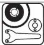
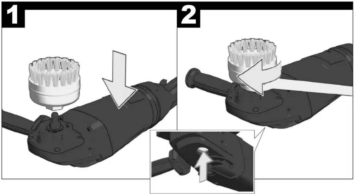
WORKING INSTRUCTIONS
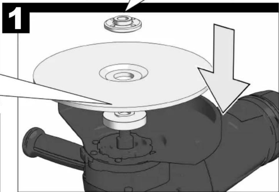
For accessories intended to be fitted with threaded hole wheel, ensure that the thread in the wheel is long enough to accept the spindle length.
Always use and store the cutting and grinding disks according to the manufacturer's instructions.
Always use the correct guard for cutting and grinding.
Always use guard with cutting guide from the accessories range for cutting stone.
The grinding surface of the centre depressed wheels must be mounted min. 2 mm below the plane of the guard lip.
The adjusting nut must be tightened before starting to work with the machine.
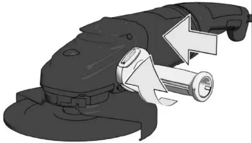
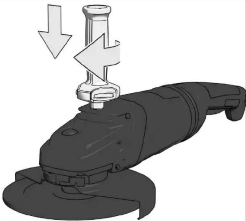
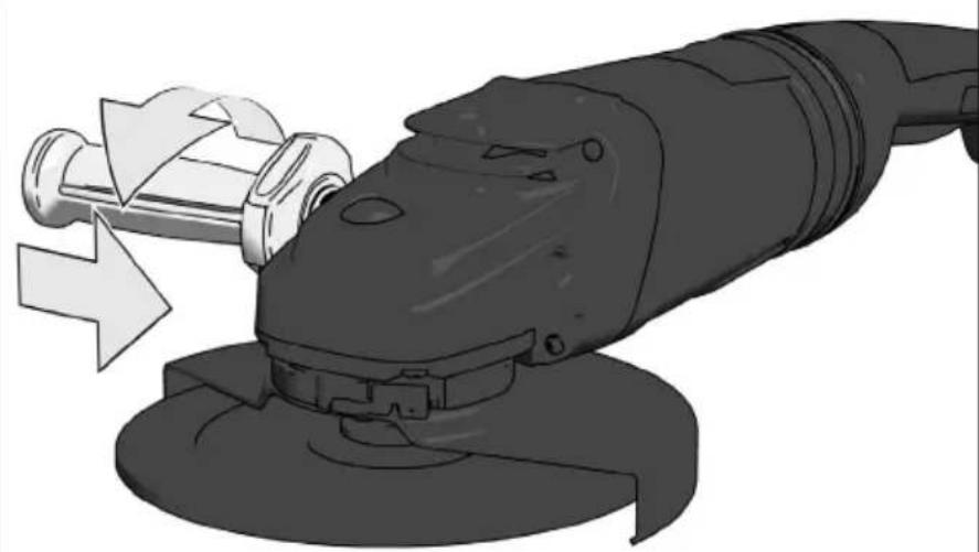
Always use the auxiliary handle.
The workpiece must be fixed if it is not heavy enough to be steady. Never move the workpiece towards the rotating disk by hand.
STARTUP PROTECTION
Machines with a lockable switch are supplied with a restart cutout. This prevents the machine restarting by itself after a power failure. When resuming work, switch the machine off and then switch it back on again.
STARTING CURRENT LIMITER + SMOOTH START
The starting current for the machine is several times greater than rated current. The starting current limiter reduces the starting current to such an extent that a fuse (16 A, slow-blow) is not tripped.
Electronic smooth start for save use prevents jerky run-up of the machine.
MAINTENANCE
The ventilation slots of the machine must be kept clear at all times.
If the supply cord of this power tool is damaged, it must be replaced by a specially prepared cord available through the service organization.
Use only Milwaukee accessories and spare parts. Should components need to be replaced which have not been described, please contact one of our Milwaukee service agents (see our list of guarantee/service addresses).
If needed, an exploded view of the tool can be ordered. Please state the Article No. as well as the machine type printed on the label and order the drawing at your local service agents or directly at: Techtronic Industries GmbH, Max-Eyth-Straße 10, 71364 Winnenden, Germany.
EC-DECLARATION OF CONFORMITY
We declare as the manufacturer under our sole responsibility that the product described under “Technical Data” fulfi lls all the relevant regulations and the directives 2011/65/EU (RoHS), 2014/30/EU, 2006/42/EC, and the following harmonized standards have been used:
EN 60745-1:2009+A11:2010
EN 60745-2-3:2011+A2:2013
EN 55014-1:2017+A11:2020
EN 55014-2:2015
EN 61000-3-2:2014
EN 61000-3-3:2013
EN IEC 63000:2018
Winnenden, 2021-01-20


Alexander Krug Managing Director
Authorized to compile the technical file.
Techtronic Industries GmbH
Max-Eyth-Straße 10
71364 Winnenden
Germany
GB-DECLARATION OF CONFORMITY
We declare as the manufacturer under our sole responsibility that the product described under “Technical Data” fulfills all the relevant provisions of the following Regulations S.I. 2008/1597 (as amended), S.I. 2016/1091 (as amended), S.I. 2012/3032 (as amended) and that the following designated standards have been used:
BS EN 60745-1:2009+A11:2010
BS EN 60745-2-3:2011+A13:2015
BS EN 55014-1:2017+A11:2020
BS EN 55014-2:2015
BS EN 61000-3-2:2014
BS EN 61000-3-3:2013
BS EN IEC 63000:2018
Winnenden, 2021-01-20

Alexander Krug
Managing Director
Authorized to compile the technical file.
Techtronic Industries GmbH
Max-Eyth-Straße 10
71364 Winnenden
Germany
SYMBOLS


CAUTION! WARNING! DANGER!
Always disconnect the plug from the socket before carrying out any work on the machine.
Please read the instructions carefully before starting the machine.
Always wear goggles when using the machine.
Wear gloves!
Do not use force.
Only for grinding.
Only for cutting work.
Accessory - Not included in standard equipment, available as an accessory.
Do not dispose of electric tools together with household waste material.
Electric tools and electronic equipment that have reached the end of their life must be collected separately and returned to an environmentally compatible recycling facility. Check with your local authority or retailer for recycling advice and collection point.

Class II tool, tool in which protection against electric shock does not rely on basic insulation only, but in which additional safety precautions, such as double insulation or reinforced insulation, are provided.
There being no provision for protective earthing or reliance upon installation conditions.
European Conformity Mark
British Conformity Mark

Regulatory Compliance Mark (RCM). Product meets applicable regulatory requirements.

Ukraine Conformity Mark


Winnenden, 2021-01-20

Alexander Krug Managing Director

DÉCLARATION CE DE CONFORMITÉ
Winnenden, 2021-01-20
Alexander Krug
Managing Director

Winnenden, 2021-01-20

Alexander Krug Managing Director

Winnenden, 2021-01-20

Alexander Krug
Managing Director
Winnenden, 2021-01-20
Alexander Krug Managing Director

Winnenden, 2021-01-20
Alexander Krug
Managing Director
Winnenden, 2021-01-20
Alexander Krug
Managing Director
Winnenden, 2021-01-20
Alexander Krug Managing Director

Winnenden, 2021-01-20
Alexander Krug Managing Director

Winnenden, 2021-01-20

Alexander Krug Managing Director

Winnenden, 2021-01-20
Alexander Krug
Managing Director
Winnenden, 2021-01-20

Alexander Krug Managing Director

Winnenden, 2021-01-20
Alexander Krug Managing Director

CE - VYHLÁSENIE KONFORMITY
Winnenden, 2021-01-20
Alexander Krug
Managing Director
Winnenden, 2021-01-20
Alexander Krug
Managing Director

Winnenden, 2021-01-20
Alexander Krug
Managing Director

UPORABA V SKLADU Z NAMEMBNOSTJO
Winnenden, 2021-01-20
Alexander Krug Managing Director
Winnenden, 2021-01-20
Alexander Krug Managing Director

Ovlašten za formiranje tehničke dokumentacije.
Techtronic Industries GmbH
Max-Eyth-Straße 10
71364 Winnenden
Germany
SIMBOLI


PAŽNJA! UPOZORENIE! OPASNOST!
Prije radova na stroju izvući utikač iz utičnice.
Molimo da pažljivo pročitate uputu o upotrebi prije puštanja u rad.
Winnenden, 2021-01-20

Alexander Krug Managing Director

Winnenden, 2021-01-20

Alexander Krug Managing Director
lgaliotas parengti techninius dokumentus.
Techtronic Industries GmbH
Max-Eyth-Straße 10
71364 Winnenden
Germany

SIMBOLIAI


DĖMESIO! JSPĖJIMAS! PAVOJUS!
Winnenden, 2021-01-20
Alexander Krug Managing Director

Winnenden, 2021-01-20
Alexander Krug
Managing Director
Winnenden, 2021-01-20
Alexander Krug
Managing Director
Winnenden, 2021-01-20

Alexander Krug Managing Director

Winnenden, 2021-01-20

Alexander Krug Managing Director

Winnenden, 2021-01-20
Alexander Krug Managing Director

Winnenden, 2021-01-20
Alexander Krug
Managing Director
Techtronic Industries (UK) Ltd
Fieldhouse Lane
Marlow Bucks SL7 1HZ
UK


(04.21)
4931 4705 23
- AG 24-230 E
- AGV 24-230 E
- AGV 24-230 GE
- AGV 26-230 GE
- Startup protection:
- Wiederanlaufschutz:
- WARNING
- ANGLE GRINDER SAFETY WARNINGS
- Kickback and Related Warnings
- Safety Warnings Specific for Grinding and Abrasive Cutting-Off Operations:
- Additional Safety Warnings Specific for Abrasive Cutting-Off Operations:
- Safety Warnings Specific for Sanding Operations:
- Safety Warnings Specific for Wire Brushing Operations:
- Additional Safety and Working Instructions
- MAINS CONNECTION
- SPECIFIED CONDITIONS OF USE
- WORKING INSTRUCTIONS
- STARTUP PROTECTION
- STARTING CURRENT LIMITER + SMOOTH START
- MAINTENANCE
- EC-DECLARATION OF CONFORMITY
- GB-DECLARATION OF CONFORMITY
- SYMBOLS
- DÉCLARATION CE DE CONFORMITÉ
- CE - VYHLÁSENIE KONFORMITY
- UPORABA V SKLADU Z NAMEMBNOSTJO
- SIMBOLI
- SIMBOLIAI
Brand : MILWAUKEE
Model : AG 24-230 E
Category : Grinder