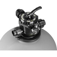
SFTM24-2.0 - Sand filter for pool Jandy - Free user manual and instructions
Find the device manual for free SFTM24-2.0 Jandy in PDF.


| Product Type | Pool Sand Filter |
| Brand | Jandy |
| Model | SFTM24-2.0 |
| Sand Capacity | 300 lb (136 kg) of #20 silica sand |
| Maximum Working Pressure | 50 psi (3.45 bar) |
| Plumbing Connections | 2 in PVC |
| Valve Type | 2 in Multiport Valve with positions Filter, Backwash, Rinse, Recirculate, Waste, Closed, Winter |
| Package Contents | Multiport valve, sand deflector, tank, shaft and lateral assembly, base, union adapters, nuts, O-rings, extensions, pressure gauge, drain valve, clamp band, PTFE tape |
| Main Functions | Filtration, backwash, rinse, recirculation, waste, closed, winterization |
| Pressure Indicator | Built-in pressure gauge to monitor working pressure |
| Maintenance | Backwash when pressure exceeds starting pressure by 10 psi; replace sand if pressure remains high |
| Winterization | Set valve to Winter position, drain filter and piping, protect from weather |
| Main Replacement Parts | R0745700 (2 in multiport valve), R0745100 (clamp band), R0745200 (drain cap), R0746100 (deflector), R0745800 (O-ring), R0746000 (lateral assembly), R0745000 (pressure gauge), R0746200 (union fittings) |
| Safety | Do not exceed 35 psi for pressure testing; do not operate valve under pressure; use a qualified contractor for installation |
Frequently Asked Questions - SFTM24-2.0 Jandy
User questions about SFTM24-2.0 Jandy
0 question about this device. Answer the ones you know or ask your own.
Ask a new question about this device
Download the instructions for your Sand filter for pool in PDF format for free! Find your manual SFTM24-2.0 - Jandy and take your electronic device back in hand. On this page are published all the documents necessary for the use of your device. SFTM24-2.0 by Jandy.
USER MANUAL SFTM24-2.0 Jandy
natural_image
Illustration of a cylindrical industrial vessel with internal components and a side-mounted valve (no text or symbols)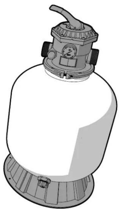
natural_image
Illustration of a pressure pump with a rotary knob and control panel (no text or symbols)Top Mount Sand Filter
Models SFTM22-1.5, SFTM24-2.0
WARNING
FOR YOUR SAFETY - This product must be installed and serviced by a contractor who is licensed and qualified in pool equipment by the jurisdiction in which the product will be installed where such state or local requirements exist. The maintainer must be a professional with sufficient experience in pool equipment installation and maintenance so that all of the instructions in this manual can be followed exactly. Improper installation and/or operation can create dangerous high pressure which can cause a catastrophic product failure and/or cause the multiport valve to be blown off possibly causing death, serious injury or property damage.
Before installing this product, read and follow all warning notices and instructions that accompany this product. Failure to follow warning notices and instructions may result in death, serious injury or property damage. Consult Zodiac customer service at 1-800-822-7933 for assistance. Improper installation and/or operation will void the warranty.
Table of Contents
Section 1. Important Safety Instructions .... 3
Section 2. Package Contents ....4
2.1 SFTM22-1.5 4
2.2 SFTM24-2.0 4
2.3 Required Tools/Equipment 5
Section 3. Equipment Location....5
3.1 Equipment Pad....5
3.2 Filter Location....5
Section 4. Initial Setup....6
4.1 Install Base....6
4.2 Install Hub and Laterals SFTM22-1.5....6
4.3 Install Hub and Laterals SFTM24-2.0....6
4.4 Fill With Sand 6
4.5 Assemble Multiport Valve 7
4.6 Install Multiport Valve 8
4.7 Plumbing 8
Section 5. Operation ....8
5.1 Filter Valve Functions 8
5.2 Initial Start up 9
5.3 Operating pressure....9
5.4 Changing the filter sand 10
5.5 Winterizing....10
Section 6. Dimensions and Replacement Parts....10
6.1 Approximate Dimensions .... 10
6.2 Replacement Parts....11
SECTION 1. IMPORTANT SAFETY INSTRUCTIONS
READ AND FOLLOW ALL INSTRUCTIONS
WARNING

natural_image
Silhouette of a person using a tool to interact with a device, no text or symbols visibleMAXIMUM OPERATING PRESSURE OF THE FILTER IS 35 PSI. NEVER SUBJECT THE FILTER TO ANY OPERATING PRESSURE EXCEEDING 35 PSI
- Do not connect the system to an unregulated city water system or other external source of pressurized water producing pressures greater than 35 PSI.
- This filter operates under high pressure. When any part of the circulating system, i.e., filter, pump, valve(s), etc. is serviced, air can enter the system and become pressurized when the system is restarted.
- Pressurized air in a system can cause product failure or also cause the dial off which can result in death, serious personal injury or property damage.
- To minimize risk of severe injury or death, the filter and/or pump should not be subjected to the piping pressurization test. Local codes may require the pool piping system to be subjected to a pressure test. These requirements are generally not intended to apply to the pool equipment such as filters or pumps. Jandy pool equipment is pressure tested at the factory.
If however, this WARNING cannot be followed and pressure testing of the piping system must include the filter and/or pump BE SURE TO COMPLY WITH THE FOLLOWING SAFETY INSTRUCTIONS.
- Check all clamps, bolts, lids, locking devices and system accessories to ensure they are properly installed and secured before testing.
- RELEASE ALL AIR in the system before testing.
• Water pressure for test must NOT EXCEED 35 PSI
• Water temperature for test must NOT EXCEED 100°F (38°C). - Limit test to 24 hours. After test, visually check system to be sure it is ready for operation.
NOTICE: These parameters apply only to Jandy equipment. For non-Jandy equipment, consult the equipment manufacturer.
To avoid electrical shock hazard, which can result in serious injury or death:
- Ensure that all electrical to the system is turned off before approaching, inspecting or troubleshooting any leaking valves or plumbing that may have caused other electrical devices in the surrounding area to get wet.
- Water discharged from an improperly positioned filter or valve can create an electrical hazard which can cause death, serious injury or property damage.
- Improper dial valve installation can cause product failure or also cause the filter dial to be blown off, which can result in death, serious personal injury or property damage.
- Never attempt to adjust or remove the dial valve when the pump is running or there is pressure in the system. this can cause product failure or also cause the filter dial to be blown off, which can result in death, serious personal injury or property damage.
CAUTION
- Maintain your pressure gauge in good working order. The pressure gauge is the primary indicator of how the filter is operating.
- Creating high vacuum levels can cause the tank vessel to crack and leak with the potential for property damage.
- Be sure that all provisions for waste water disposal meet local, provincial or national codes. During any backwash or draining process, 100 gallons or more of water will be discharged. Do not discharge water where it will cause flooding or damage.
- To avoid damaging the laterals (spokes), slowly add the filter media until the laterals are fully covered. Consult Installation and Operation Manual for complete sand fi lling instructions Cracked or broken laterals (spokes) will cause sand to be discharged to the pool.
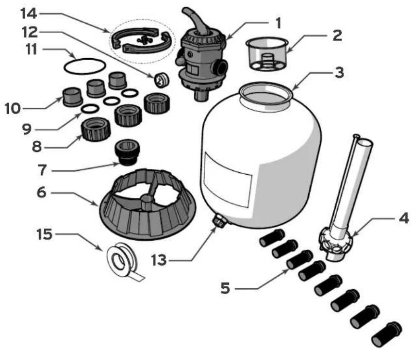
SECTION 2. PACKAGE CONTENTS
2.1 SFTM22-1.5
Unpack and check contents. If any parts are missing or damaged please call Customer Support at 1-800-822-7933.
| ITEM | DESCRIPTION QTY. | ||
| 1 | Multiport Valve (1.5") 1 | ||
| 2 | Sand Defl ector 1 | ||
| 3 | Filter Tank 1 | ||
| 4 | Lateral Hub Assembly 1 | ||
| 5 | Lateral 8 | ||
| 6 | Base 1 | ||
| 7 | Union Adapter | 1 | |
| 8 | Union Nut | 3 | |
| 9 | Union O-Ring | 3 | |
| 10 | Tailpiece | 3 | |
| 11 | Valve O-Ring | 1 | |
| 12 | Pressure Gauge | 1 | |
| 13 | Drain Valve | 1 | |
| 14 | Clamp Arm | 2 | |
| Retaining Bolt | 2 | ||
| Capture Nut | 2 | ||
| 15 | PTFE Tape | 1 | |
2.2 SFTM24-2.0
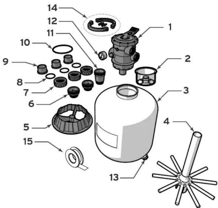
Unpack and check contents. If any parts are missing or damaged please call Customer Support at 1-800-822-7933.
| ITEM | DESCRIPTION | QTY. | |
| 1 | Multiport Valve (2") | 1 | |
| 2 | Sand Defl ector | 1 | |
| 3 | Filter Tank | 1 | |
| 4 | Lateral & Hub Assembly | 1 | |
| 5 | Base | 1 | |
| 6 | Union Adapter | 2 | |
| 7 | Union Nut | 3 | |
| 8 | Union O-Ring | 3 | |
| 9 | Tailpiece | 3 | |
| 10 | Valve O-Ring | 1 | |
| 11 | Extension Adapter | 1 | |
| 12 | Pressure Gauge | 1 | |
| 13 | Drain Valve | 1 | |
| 14 | Clamp Arm | 2 | |
| Retaining Bolt | 2 | ||
| Capture Nut | 2 | ||
| 15 | PTFE Tape | 1 | |
2.3 REQUIRED TOOLS/EQUIPMENT
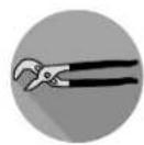
The following list of equipment should be present and available to the installer at the time of install. Failure to use the appropriate safety and installation equipment could lead to personal injury or property damage.
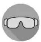
Safety Eyewear Level Scoop Channel Locks

Gloves

Screwdriver, Phillips Head

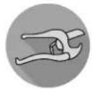
PVC Cutter PVC Pipe Adhesive
SECTION 3. EQUIPMENT LOCATION
All pool water recirculation system components need to be installed in accordance with the standards and instructions in effect in your county or municipality. Utmost care must be taken to ensure that the equipment is located such that it is able to be safely operated and maintained.
3.1 EQUIPMENT PAD
The filter along with the other primary components of your pool water recirculation system should be installed on a level, prepared footing, which is capable of supporting the weight of the filter (see Section 6) and which will accommodate the use of anchoring bolts to secure the equipment in place. Check local building codes for any additional requirements. If possible the equipment pad area should be:
• Dry
- Well ventilated
• Supplied with sufficient drainage
- Out of direct sunlight
- Located away from eaves or overhangs where rain gutters are not installed
- Away from overhanging trees or other foliage that may produce waste or debris of any kind that could clog, block or otherwise disrupt the regular operation and maintenance of the equipment
- As close to the primary body of water as possible. Additional pipe length reduces efficiency due to pipe friction
3.2 FILTER LOCATION
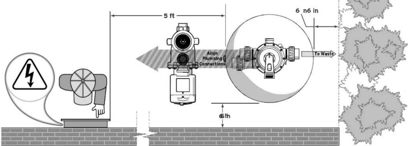
On the equipment pad, the filter should be positioned so that it is:
- Level
- At least 6 inches away from walls and landscaping for servicing
-
At least 5 feet away from any electrical controls or inputs.
-
In line with other equipment in order to minimize turns in plumbing which can result in diminished efficiency
• Stationary and not subject to movement
natural_image
Three stylized, spiky gray flower-like shapes arranged vertically (no text or symbols)SECTION 4. INITIAL SETUP
4.1 INSTALL BASE
- Turn filter tank upside down.
a Position the base so that the retention nodes are between the lock tabs.
b Turn clockwise until the lock tabs are securely seated under the retention nodes.

natural_image
Circular mechanical component diagram with labeled parts (a and b), no readable text or symbols beyond labels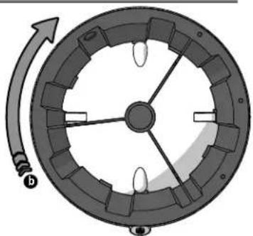
natural_image
Diagram of a circular mechanical component with internal gears and a rotating arrow (no text or symbols)4.2 INSTALL HUB AND LATERALS SFTM22-1.5
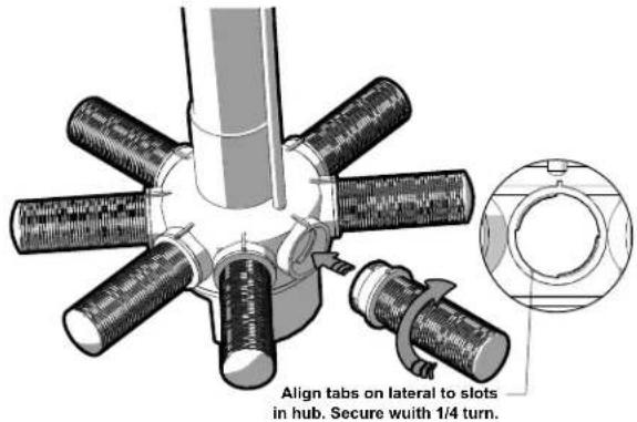
- Inspect the laterals and lateral hub assembly for damage or debris. Replace or clean where needed.
- Insert the lateral hub assembly into the filter tank.
- Reach into filter tank and install each lateral to the hub.
- Each lateral requires a single quarter turn. Ensure that the laterals are snug. DO NOT OVERTIGHTEN.
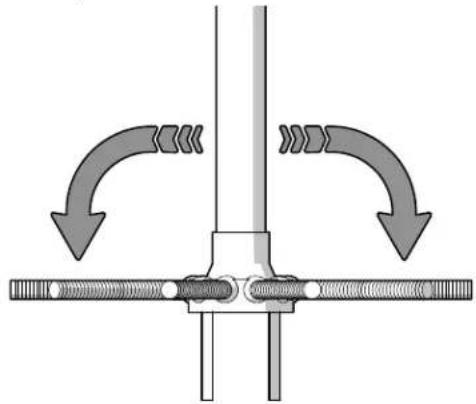
4.3 INSTALL HUB AND LATERALS SFTM24-2.0
- Inspect the laterals and lateral hub assembly for damage or debris. Replace or clean where needed.
- Insert the lateral hub assembly into the filter tank.
- Reach into filter tank and extend each lateral into a fully horizontal position.
natural_image
Mechanical diagram showing a valve or connector with directional arrows indicating flow or movement (no text or symbols present)4.4 FILL WITH SAND
CAUTION
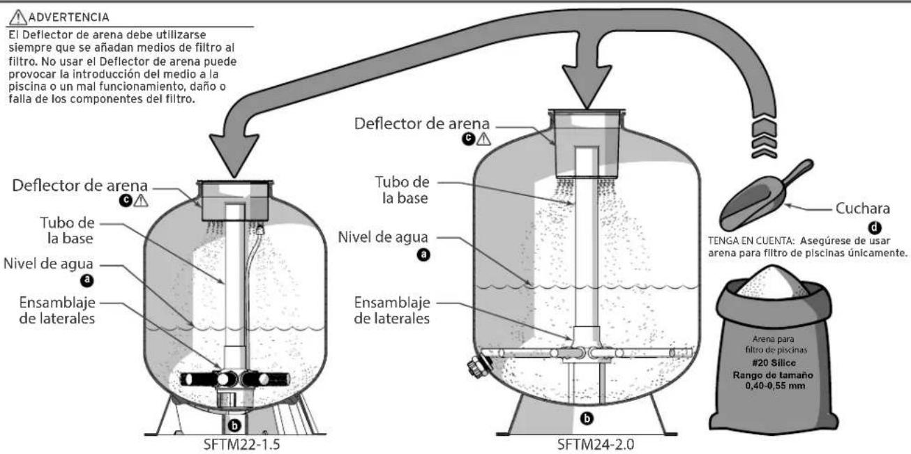
The Sand Deflector must be used at any time filter media is being added to the filter. Failure to use the Sand Deflector may result in filter media intrusion into the pool and/or malfunction, damage or failure of the filter components.
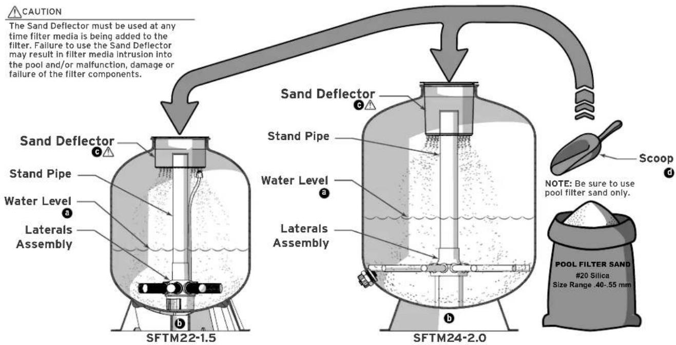
The proper type, amount and cleanliness of your filter sand is critical to the proper function and longevity of your equipment.
| #20 Silica Sand (for pool fil ter use only)Size Range .40-.55 mm | NOTE: Alternate Filter Media | |
| Model Lbs. (kg) | Manufacturers directions must be followed for any alternate media. Use of other media may deliver unexpected results and may void the warranty. | |
| SFTM22-1.5 250 (113) | ||
| SFTM24-2.0 300 (136) | ||
-
Make sure the filter is level on the equipment pad.
-
Prepare filter for sand.
a Fill the filter 1/3 - 1/2 full of water before adding sand.
- This will minimize any undue strain on the laterals when adding sand.
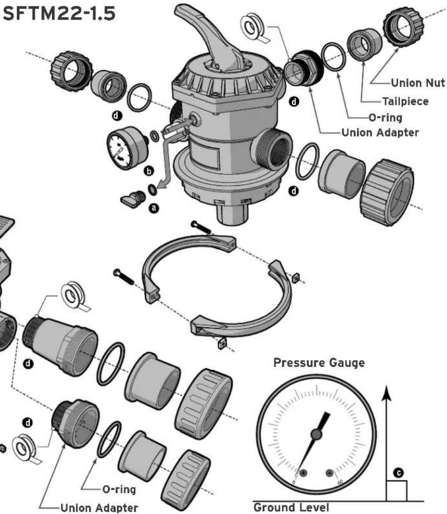
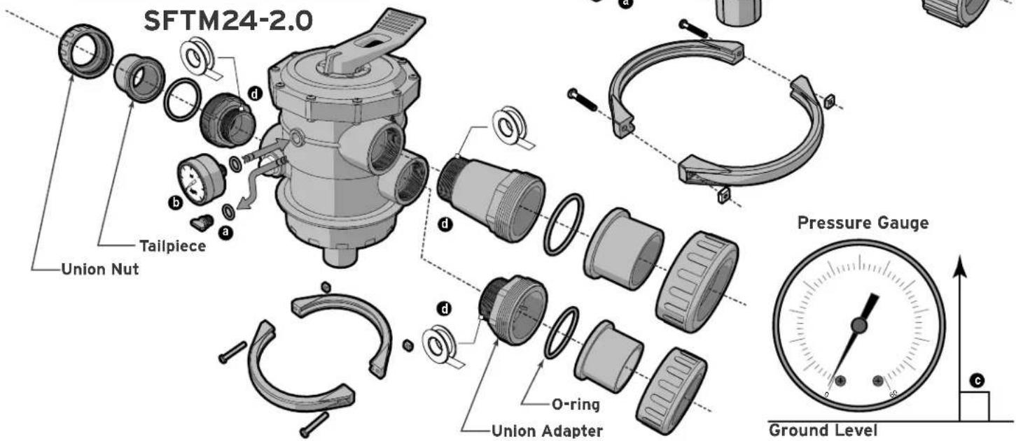
4.5 ASSEMBLE MULTIPORT VALVE
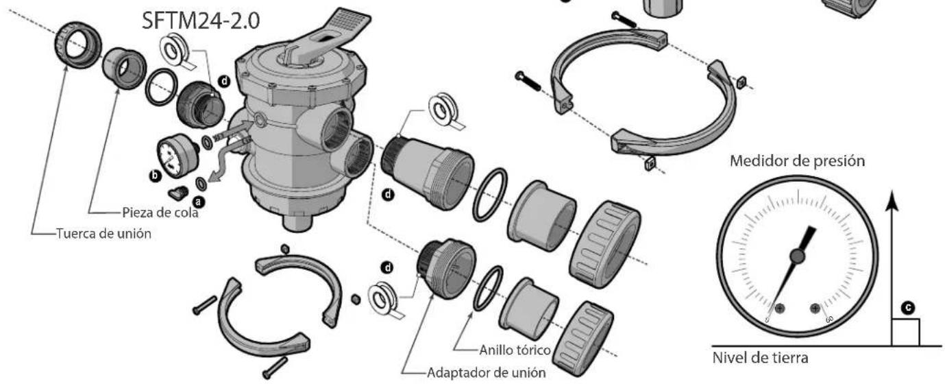
- Install pressure gauge.
a Remove the plug from the pressure gauge port.
b Install pressure gauge.
- Screw into place until snug. DO NOT OVERTIGHTEN.
- If possible, orient the gauge so that it is horizontally aligned. The included Teflon® tape can be used to aid in getting the appropriate orientation and fit.
c If possible, orient the gauge so that it is right reading and perpendicular to ground level.

WARNING
PVC cement and primer can produce vapors that can be hazardous to your health. Use PVC cement to join pipes only in a well ventilated area where vapors cannot accumulate.
Pipe dope should NEVER be used on plastic threads. Pipe dope will severely weaken the plastic, causing leakage and may cause the plastic to fracture. DO NOT OVERTIGHTEN
b Ensure stand pipe is seated at the bottom of the filter tank.
© Install the clear plastic stand pipe shield.
- The shield should completely cover the pipe opening.
- Special care should be taken to avoid getting filter sand into the stand pipe.
c Using a small scoop, slowly and evenly add sand to the filter. - Be sure to allow the stand pipe shield to fully drain between each scoop to avoid spilling.
When all filter sand has been added:
- Remove stand pipe shield and store for future use.
Install unions at the filter's Pump, Return and Waste ports.
- SFTM22-1.5 will use a union adapter at the waste port only.
- SFTM24-2.0 will use union adapters at the waste and return ports. The extension adapter will be used at the pump port.
- Apply 4-6 wraps of PTFE (plumbers) tape for each union adapter installed at the multiport valve. Only install PTFE (plumbers) tape on the adapter threads at the valve ports.
- Do not use PTFE (plumbers) tape on union nut threads.
4.6 INSTALL MULTIPORT VALVE
- Flip the valve assembly upside down. Install the valve/tank 0-ring so that it is seated below the valve body flange.
- Seat valve onto filter tank with standpipe secured in center port of the multiport valve body.
- Make sure pump and return ports are oriented so that bends and/or joints in plumbing are minimized.
- Position the valve clamp so that it captures both the valve body flange and the filter tank.
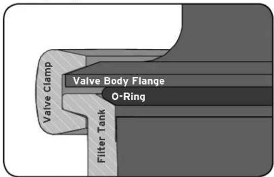
- Position multiport valve clamp so that the bolts will be accessible after the filter has been plumbed.
- Use a Phillips head screw driver to secure the clamp.
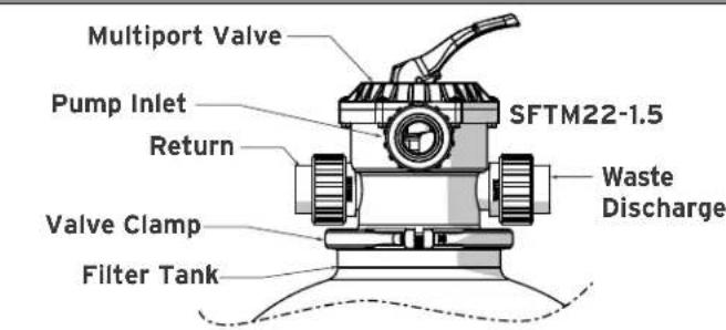
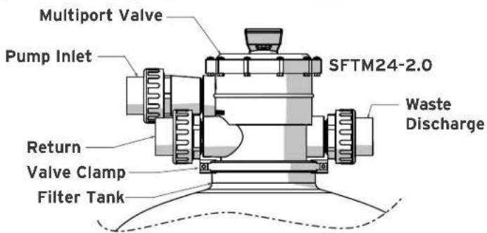
- Alternate tightening of the valve clamp from side to side.
- Do not overtighten clamp.
4.7 PLUMBING
Make sure all plumbing connections are in accordance with local plumbing and building codes.
- Using appropriate pipe adhesive, connect the filter to the pool water recirculation system.
- Plumb the pump discharge line to the Pump Port on the Multiport Valve.
- Plumb the return line to the Return Port on the Multiport Valve.
- Plumb the waste line to the Waste Port on the Multiport Valve.
- Connect the pipes using the unions supplied with the filter. Do not use PTFE (plumbers) tape or pipe dope on any union nuts. Assemble the unions dry and hand tighten.
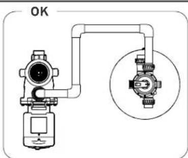
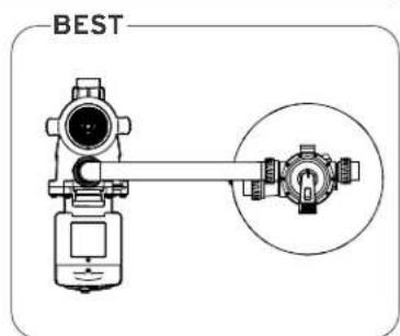
- SFTM22-1.5 piping adapters are sized for 1.1/2" PVC pipe, SFTM24-2.0 piping adapters are sized for 2" PVC pipe. In order to reduce pressure loss, 2" (minimum) piping is recommended.
This filter operates under pressure. When clamped properly and operated without air in the water system, this filter will operate in a safe manner. All plumbing
connections should be in accordance with local plumbing and building codes. Do not use pipe joint compound, glue or solvent on the union nut threads.
5.1 FILTER VALVE FUNCTIONS
Filter pump must be turned off prior to making any adjustments to the multiport valve. When starting the pump after making adjustments to the valve be sure to stand clear of the filter. Ensure that all provisions for waste water disposal meet local, state or national codes.
Set Valve Handle to:
- FILTER: Water passes through filter sand and returns back to the pool. Set for Normal filtration operation. Multiport Valve should be in this position for all typical filtration and sanitation circulation.
- WASTE: Water bypasses filter sand and is routed to waste port.
-
RECIRCULATE: Water bypasses filter sand and is returned to the pool.
-
CLOSED: Closes all passages through the Multiport Valve.
- WINTER This valve position leaves the multiport valve handle disengaged and all passages through the valve open for draining. Once the filter is drained, it is recommended that the valve handle be kept in the Winter position.
- BACKWASH: Water passes through filter sand in reverse and is sent to the waste port. With pump running, periodically check water clarity in sight glass. Once water is visibly clear, the backwash cycle is complete.
- RINSE: Water passes through filter sand to waste. Use after backwash cycle to clean debris from the Multiport Valve. Rinse should run for 1-2 minutes.
5.2 INITIAL START UP
- Make sure that all connections are secure and that any glued piping connections or joints have had sufficient time to cure.
- Backwash filter sand.
- Set multiport valve to backwash.
- Turn on filter pump.
• Water will discharge from waste port.
- While pump is running, periodically check the water clarity through the sight glass or at the waste port.
- Once water is visibly clear the backwash cycle is complete.
- See "5.1 Filter Valve Functions" on page 8 for details.
-
Turn off filter pump.
-
Set valve to rinse.
-
Stand clear of filter and turn on the filter pump.
• Water will discharge from waste port.
-
Allow filter to run for 1-2 minutes.
-
Turn off filter pump.
-
Set multiport valve to filter.
-
Stand clear of filter.
-
Turn on filter pump and allow it to run normally.
• Water will discharge to pool from return port.
- Take the pressure reading from the pressure gage while the filter pump is running at its typical filtration RPM.
- Set the pressure gage to clean using the filtration PSI as the "clean" mark.
natural_image
Silhouette of a person reacting to a device with radiating lines, no text or symbols presentMAXIMUM OPERATING PRESSURE OF THE FILTER IS 35 PSI. NEVER SUBJECT THE FILTER TO ANY OPERATING PRESSURE EXCEEDING 35 PSI
- Do not connect the system to an unregulated
city water system or other external source of pressurized water producing pressures greater than 35 PSI.
- This fi Iter operates under high pressure. When any part of the circulating system, i.e., fi Iter, pump, valve(s), etc. is serviced, air can enter the system and become pressurized when the system is restarted.
- Pressurized air in a system can cause product failure or also cause the dial valve to be blown off which can result in death, serious personal injury or property damage.
- To minimize risk of severe injury or death, the filter and/or pump should not be subjected to
the piping pressurization test. Local codes may require the pool piping system to be subjected to a pressure test. These requirements are generally not intended to apply to the pool equipment such as fi Iters or pumps. Jandy pool equipment is pressure tested at the factory.
If however, this WARNING cannot be followed and pressure testing of the piping system must include the fi Iter and/or pump BE SURE TO COMPLY WITH THE FOLLOWING SAFETY INSTRUCTIONS.
- check all clamps, bolts, lids, lock rings and system accessories to ensure they are properly installed and secured before testing.
- RELEASE ALL AIR in the system before testing.
• Water pressure for test must NOT EXCEED 35 PSI
• Water temperature for test must NOT EXCEED 100^ F ( 38^ C). - Limit test to 24 hours. After test, visually check system to be sure it is ready for operation.
NOTICE: These parameters apply only to Jandy equipment. for non-Jandy equipment, consult the equipment manufacturer.
The filter is designed to operate effectively based on the performance curve listed below. At no time is the filter to be subjected to internal pressures greater than 50 psi.
- After initial startup run the filter pump for several minutes.
- Take note of the running pressure and set the "clean" indicator on the pressure gage dial to the filtration PSI.
-
Check the operating pressure regularly at least once a week.
-
Performing a backwash procedure is required once the pressure consistently reads 10 PSI greater than the initial startup pressure, DO NOT EXCEED 35 PSI.
- Follow backwash and rinse procedure. See "5.1 Filter Valve Functions" on page 8 and "5.2 Initial Start up" on page 9.
- If after backwashing the filter you are unable to get the pressure to lower sufficiently to ensure operational pressures below 35 PSI you will need to replace the filter sand.
SFTM22-1.5 AND SFTM24-2.0 PERFORMANCE
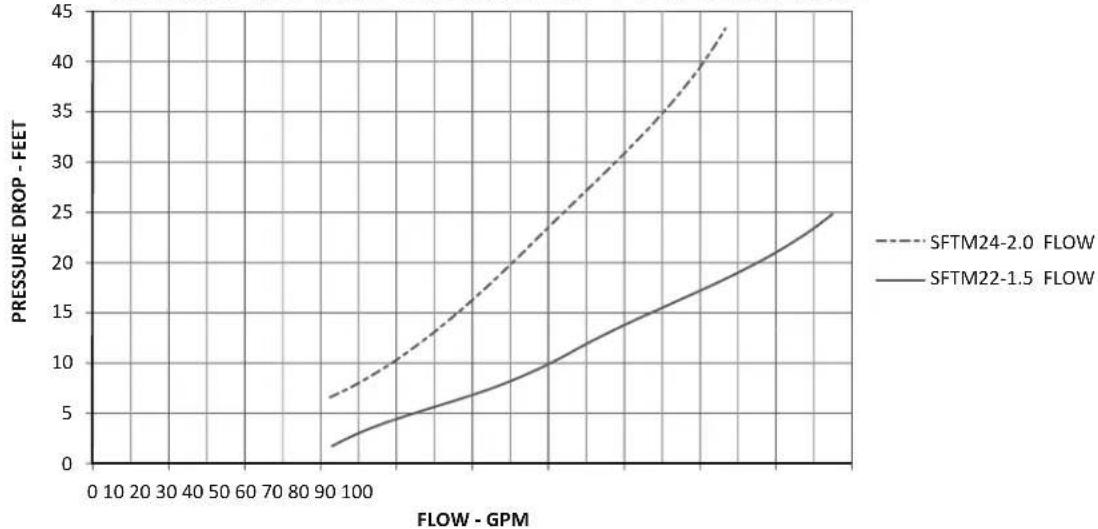
line
| FLOW - GPM | SFTM24-2.0 FLOW | SFTM22-1.5 FLOW | | ---------- | --------------- | --------------- | | 0 | 6 | 2 | | 100 | 10 | 4 | | 200 | 15 | 6 | | 300 | 20 | 8 | | 400 | 25 | 10 | | 500 | 30 | 12 | | 600 | 35 | 14 | | 700 | 40 | 16 | | 800 | 45 | 18 | | 900 | 48 | 20 | | 1000 | 50 | 25 |5.4 CHANGING THE FILTER SAND
Filter sand will need to be removed from the multiport valve opening.
- Loosen bolts from clamp.
- Remove clamp.
- Remove Multiport Valve.
-
Use a wet/dry vacuum or similar suction device to vacuum old sand from filter tank.
-
Keep enough water in filter tank to keep sand in a semi fluid "slurry" state
- Using steps from "4.4 Fill With Sand" on page 6 replace the sand in the filter.
WARNING
Be sure to dispose of used filter sand appropriately. Used filter sand is not appropriate for human or pet contact
5.5 WINTERIZING
Turn off the pump.
- Move the Multiport valve handle to "Winter".
-
Remove any drain plugs from the filter.
-
Vent the filter by removing the pressure gauge or disconnecting one of the unions.
- Drain system piping of all water.
- Cover the system with a tarpaulin or plastic sheet to protect from the weather.
SECTION 6. DIMENSIONS AND REPLACEMENT PARTS
6.1 APPROXIMATE DIMENSIONS
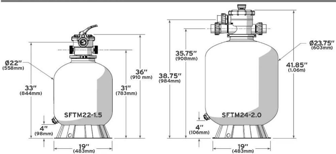
6.2 REPLACEMENT PARTS
6.2.1 SFTM22-1.5
| ITEM | Part # Description QTY | ||
| 1 | R0744600 | Complete Multi-Port Valve w/Clamp Assembly (1.5" MPV) 1 | |
| 2 | R0744700 | Top Rotor Assembly 1 | |
| 3 | R0745100 | Flange Clamp Assembly 1 | |
| 4 | R0745200 | Drain Cap and O-Ring 1 | |
| 5 | R0745300 | Lateral (Full Set) 8 | |
| 6 | R0745400 | Lateral & Standpipe Assembly 1 | |
| 7 | R0745500 | Sand Deflector | 1 |
| 8 | R0745800 | O-Ring Valve Tank | 1 |
| 9 | R0745000 | Pressure Gauge Assembly | 1 |
| 10 | R0745600 | Complete 1.5" Unions Kit | 3 |
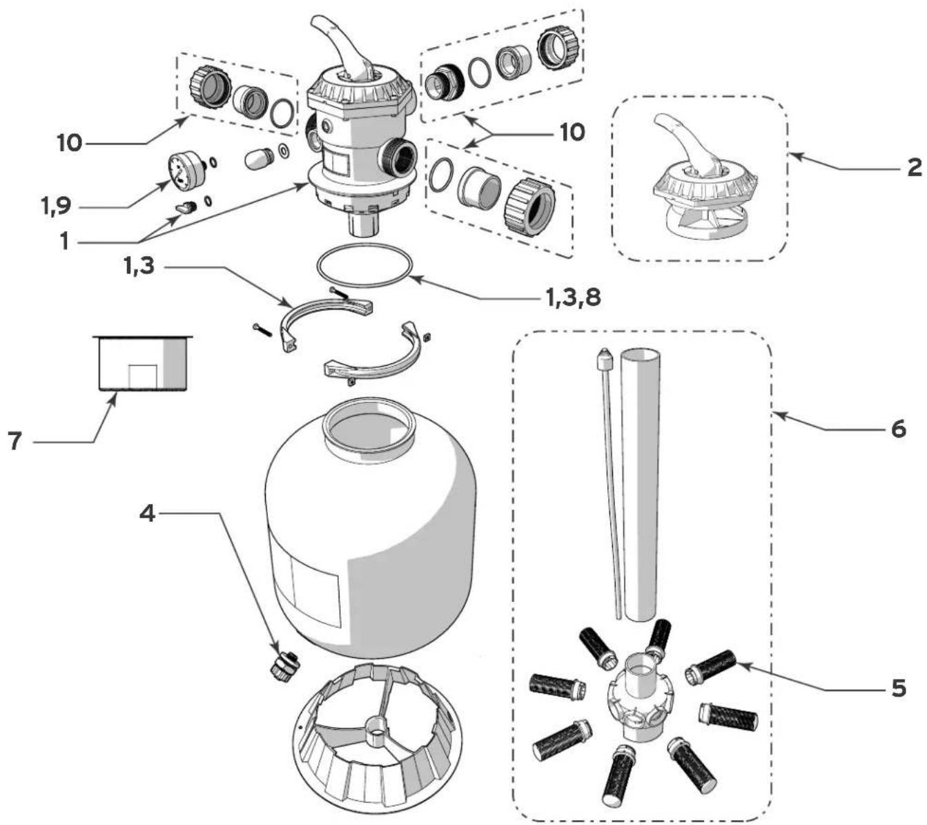
6.2.2 SFTM24-2.0
| ITEM | Part # Description QTY | ||
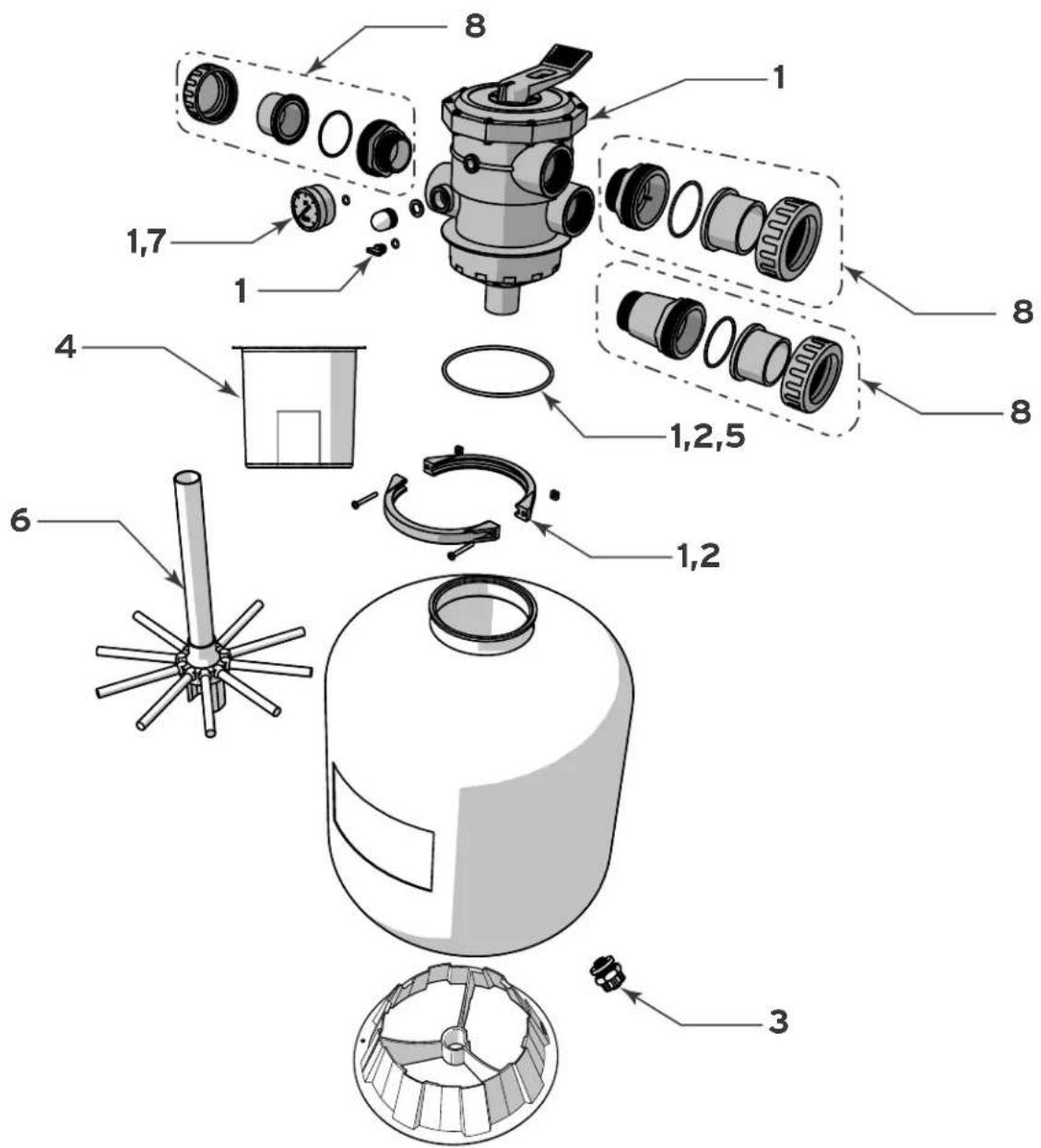
| 1 | R0745700 | Complete Multi-Port Valve w/Clamp Assembly (2" MPV) 1 | |
| 2 | R0745100 | Flange Clamp Assembly 1 | |
| 3 | R0745200 | Drain Cap and O-Ring 1 | |
| 4 | R0746100 | Sand Deflector 1 | |
| 5 | R0745800 | O-ring, Valve/Tank 1 | |
| 6 | R0746000 | Lateral & Standpipe Assembly 1 | |
| 7 | R0745000 | Pressure Gauge Assembly | 1 |
| 8 | R0746200 | Complete 2" Unions With Adapter Kit | 1 |
NOTES
NOTES
NOTES
Zodiac Pool Systems, Inc.
2620 Commerce Way, Vista, CA 92081
1.800.822.7933 | www.jandy.com
Zodiac Pool Systems Canada, Inc.
2115 South Service Road West, Unit 3
Oakville, ON L6L 5W2
1.888.647.4004 | www.ZodiacPoolSystems.ca
ZODIAC® is a registered trademark of Zodiac International,
S.A.S.U., used under license. All other trademarks referenced
herein are the property of their respective owners.
©2016 Zodiac Pool Systems, Inc. H0579200_REVD
natural_image
Illustration of a cylindrical industrial vessel with internal components and a side-mounted valve (no text or symbols)
natural_image
Illustration of a pressure pump with a rotary knob and control panel (no text or symbols)natural_image
Silhouette of a person using a tool to interact with a device, no text or symbols visibleLA PRESSION DE FONCTIONNEMENT MAXIMALE DU FILTRE EST DE 35 PSI. NE SOUMETTEZ JAMAIS LE FILTRE À UNE PRESSION DE FONCTIONNEMENT DÉPASSANT 35 PSI
2.2 SFTM24-2.0
2.3 OUTILS/ÉQUIPEMENTS REQUIS
natural_image
Three stylized, spiky, flower-like shapes with no text or symbolsSECTION 4. CONFIGURATION INITIALE
4.1 INSTALLATION DE LA BASE
natural_image
Circular mechanical component diagram with labeled parts (a and b), no readable text or symbols beyond labels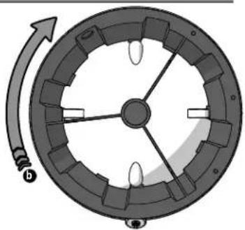
natural_image
Diagram of a circular mechanical component with internal blades and a rotating arrow, no text or symbols present.4.2 INSTALLATION DE L'AXE ET DES EMBRANCHEMENTS SFTM22-1.5
natural_image
Technical illustration of a mechanical assembly with multiple bolted components and a close-up view of a circular component (no text or symbols)natural_image
Pure mechanical diagram showing two curved arrows pointing to a central component with no text or symbols4.4 REMPLISSAGE DE SABLE

ATTENTION
natural_image
Technical diagram of a mechanical device with pipe and circular inset view (no text or symbols)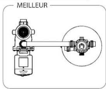
natural_image
Silhouette of a person using a welding torch to smoke or smoke from a gas cylinder (no text or symbols)LA PRESSION DE FONCTIONNEMENT MAXIMALE DU FILTRE EST DE 35 PSI. NE SOUMETTEZ JAMAIS LE FILTRE À UNE PRESSION DE FONCTIONNEMENT DÉPASSANT 35 PSI
6.1 DIMENSIONS APPROXIMATIVES
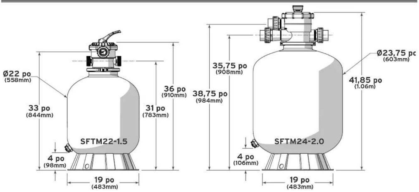
6.2 PIÈCES DE RECHANGE
6.2.1 SFTM22-1.5
6.2.2 SFTM24-2.0
REMARQUES
REMARQUES
REMARQUES
Zodiac Pool Systems, Inc.
2620 Commerce Way, Vista, CA 92081
1.800.822.7933 | www.jandy.com
Zodiac Pool Systems Canada, Inc.
2115 South Service Road West, Unit 3
Oakville, ON L6L 5W2
1.888.647.4004 | www.ZodiacPoolSystems.ca
natural_image
Illustration of a cylindrical industrial vessel with internal components and a side-mounted valve (no text or symbols)
natural_image
Illustration of a pressure regulator device with a cylindrical body and control knob (no text or symbols)Filtro de arena de montaje superior Modelos SFTM22-1.5, SFTM24-2.0
ADVERTENCIA
natural_image
Silhouette of a person using a tool to interact with a device, surrounded by radiating lines (no text or symbols)2.2 SFTM24-2.0
natural_image
Three stylized, spiky gray flower-like shapes arranged vertically (no text or symbols)natural_image
Technical illustration of a mechanical assembly with six bolted components and a separate circular component (no text or symbols)natural_image
Circular mechanical component diagram with labeled parts (a, b) and center point (no text or symbols beyond labels)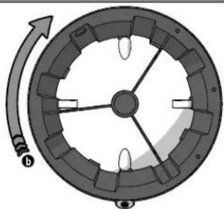
natural_image
Diagram of a circular mechanical component with internal stator and rotor, showing rotational motion indicated by arrows (no text or symbols)natural_image
Mechanical diagram showing a valve or connector with directional arrows indicating flow or movement (no text or symbols present)4.4 LLENADO CON ARENA
natural_image
Technical diagram of a mechanical device with a circular inset showing a device (no text or symbols)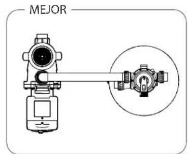
natural_image
Silhouette of a person using a welding torch to interact with a large vessel (no text or symbols)6.2.2 SFTM24-2.0
NOTAS
NOTAS
NOTAS
Zodiac Pool Systems, Inc.
2620 Commerce Way, Vista, CA 92081
1.800.822.7933 | www.jandy.com
Zodiac Pool Systems Canada, Inc.
2115 South Service Road West, Unit 3
Oakville, ON L6L 5W2
1.888.647.4004 | www.ZodiacPoolSystems.ca
- Top Mount Sand Filter
- Models SFTM22-1.5, SFTM24-2.0
- WARNING
- Table of Contents
- Section 1. Important Safety Instructions .... 3
- Section 2. Package Contents ....4
- Section 3. Equipment Location....5
- Section 4. Initial Setup....6
- Section 5. Operation ....8
- Section 6. Dimensions and Replacement Parts....10
- SECTION 1. IMPORTANT SAFETY INSTRUCTIONS
- READ AND FOLLOW ALL INSTRUCTIONS
- MAXIMUM OPERATING PRESSURE OF THE FILTER IS 35 PSI. NEVER SUBJECT THE FILTER TO ANY OPERATING PRESSURE EXCEEDING 35 PSI
- CAUTION
- SECTION 2. PACKAGE CONTENTS
- SFTM22-1.5
- SFTM24-2.0
- REQUIRED TOOLS/EQUIPMENT
- SECTION 3. EQUIPMENT LOCATION
- EQUIPMENT PAD
- FILTER LOCATION
- SECTION 4. INITIAL SETUP
- INSTALL BASE
- INSTALL HUB AND LATERALS SFTM22-1.5
- INSTALL HUB AND LATERALS SFTM24-2.0
- FILL WITH SAND
- ASSEMBLE MULTIPORT VALVE
- INSTALL MULTIPORT VALVE
- PLUMBING
- FILTER VALVE FUNCTIONS
- INITIAL START UP
- CHANGING THE FILTER SAND
- WINTERIZING
- SECTION 6. DIMENSIONS AND REPLACEMENT PARTS
- REPLACEMENT PARTS
- NOTES
- LA PRESSION DE FONCTIONNEMENT MAXIMALE DU FILTRE EST DE 35 PSI. NE SOUMETTEZ JAMAIS LE FILTRE À UNE PRESSION DE FONCTIONNEMENT DÉPASSANT 35 PSI
- OUTILS/ÉQUIPEMENTS REQUIS
- SECTION 4. CONFIGURATION INITIALE
- INSTALLATION DE LA BASE
- INSTALLATION DE L'AXE ET DES EMBRANCHEMENTS SFTM22-1.5
- REMPLISSAGE DE SABLE
- ATTENTION
- PIÈCES DE RECHANGE
- REMARQUES
- Filtro de arena de montaje superior Modelos SFTM22-1.5, SFTM24-2.0
- ADVERTENCIA
- LLENADO CON ARENA
- NOTAS
Brand : Jandy
Model : SFTM24-2.0
Category : Sand filter for pool