EASY PRF0129429 - Basket ELICA - Free user manual and instructions
Find the device manual for free EASY PRF0129429 ELICA in PDF.

User questions about EASY PRF0129429 ELICA
0 question about this device. Answer the ones you know or ask your own.
Ask a new question about this device
Download the instructions for your Basket in PDF format for free! Find your manual EASY PRF0129429 - ELICA and take your electronic device back in hand. On this page are published all the documents necessary for the use of your device. EASY PRF0129429 by ELICA.
USER MANUAL EASY PRF0129429 ELICA
READ AND SAVE THESE INSTRUCTIONS LISEZ CES INSTRUCTIONS ET CONSERVEZ-LES
THIS MANUAL IS FOR USE ONLY IN USA AND CANADA
CE MANUEL EST UNIQUEMENT VALABLE AUX USA ET AU CANADA
READ AND SAVE THESE INSTRUCTIONS
APPROVED FOR RESIDENTIAL APPLIANCES FOR RESIDENTIAL USE ONLY READ AND SAVE THESE INSTRUCTIONS
PLEASE READ ENTIRE INSTRUCTIONS BEFORE PROCEEDING.
INSTALLATION MUST COMPLY WITH ALL LOCAL CODES.
IMPORTANT: Save these Instructions for the Local Electrical Inspector's use.
INSTALLER: Please leave these Instructions with this unit for the owner.
OWNER: Please retain these instructions for future reference.
Safety Warning: Turn off power circuit at service panel and lock out panel, before wiring this appliance.
Requirement: 120V, 60 Hz, 15 or 20 A Branch Circuit
Removing the packaging
CAUTION!
Remove carton carefully, Wear gloves to protect against sharp edges.
WARNING!
Remove the protective film covering the product before putting into operation.
Note: The parts marked with the symbol (^*) are optional accessories supplied only with some models or otherwise not supplied, but available for purchase.

Important safety Notice
CAUTION
FOR GENERAL VENTILATING USE ONLY. DO NOT USE TO EXHAUST HAZARDOUS OR EXPLOSIVE MATERIALS OR VAPOURS.
WARNING
TO REDUCE THE RISK OF FIRE, ELECTRIC SHOCK, OR INJURY TO PERSONS, OBSERVE THE FOLLOWING:
A. Use this unit only in the manner intended by the manufacturer. If you have questions, contact the manufacturer.
B. Before servicing or cleaning the unit, switch power off at service panel and lock service panel disconnecting means to prevent power from being switched on accidentally. When the service disconnecting means cannot be locked, securely fasten a prominent warning
device, such as a tag, to the service panel.
WARNING
TO REDUCE THE RISK OF FIRE, ELECTRIC SHOCK, OR INJURY TO PERSONS, OBSERVE THE FOLLOWING:
A. Installation Work and Electrical Wiring Must Be Done By Qualified Person(s) In Accordance With All Applicable Codes & Standards, Including Fire-rated Construction.
B. Sufficient air is needed for proper combustion and exhausting of gases through the flue (Chimney) of fuel burning equipment to prevent back- drafting. Follow the heating equipment manufacturers guideline and safety standards such as those published by the National Fire Protection Association (NFPA), the American Society for Heating, Refrigeration and Air Conditioning Engineers (ASHRAE), and the local code authorities.
C. When cutting or drilling into wall or ceiling, do not damage electrical wiring and other hidden utilities.
D. Ducted systems must always be vented to the outdoors.
WARNING
TO REDUCE THE RISK OF FIRE, USE ONLY METAL DUCT WORK.
Install this hood in accordance with all requirements specified.
WARNING
To Reduce The Risk Of Fire Or Electric Shock, Do Not Use This Hood With Any External Solid State Speed Control Device.
WARNING
TO REDUCE THE RISK OF A RANGE TOP GREASE FIRE.
a) Never leave surface units unattended at high settings. Boilovers cause smoking and greasy spillovers that may ignite. Heat oils slowly on low or medium settings.
b) Always turn hood ON when cooking at high heat or when flambeing food (I.e. Crepes Suzette, Cherries Jubilee, Peppercorn Beef Flambe').
c) Clean ventilating fans frequently. Grease should not be allowed to accumulate on fan or filter.
d) Use proper pan size. Always use cookware appropriate for the size of the surface element.
WARNING
TO REDUCE THE RISK OF INJURY TO PERSONS, IN THE
EVENT OF A RANGE TOP GREASE FIRE, OBSERVE THE FOLLOWINGa:
a) SMOTHER FLAMES with a close-fitting lid, cookie sheet, or other metal tray, then turn off the gas burner or the electric element. BE CAREFUL TO PREVENT BURNS. If the flames do not go out immediately, EVACUATE AND CALL THE FIRE DEPARTMENT.
b) NEVER PICK UP A FLAMING PAN - you may be burned.
c) DO NOT USE WATER, including wet dishcloths or towels - a violent steam explosion will result.
d) Use an extinguisher ONLY if:
1) You know you have a class ABC extinguisher, and you already know how to operate it.
2) The fire is small and contained in the area where it started.
3) The fire department is being called.
4) You can fight the fire with your back to an exit.
aBased on "Kitchen Firesafety Tips" published by NFPA.
OPERATION
a. Always leave safety grills and filters in place. Without these components, operating blowers could catch onto hair, fingers and loose clothing.
The manufacturer declines all responsibility in the event of failure to observe the instructions given here for installation, maintenance and suitable use of the product. The manufacturer further declines all responsibility for injury due to negligence and the warranty of the unit automatically expires due to improper maintenance.
Electrical & Installation requirements
Electrical requirements
IMPORTANT
Observe all governing codes and ordinances.
It is the customer's responsibility:
To contact a qualified electrical installer.
To assure that the electrical installation is adequate and in conformance with National Electrical Code, ANSI/NFPA 70 - latest edition, or CSA Standards C22.1-94, Canadian Electrical Code, Part 1 and C22.2 No.0-M91 - latest edition* and all local codes and ordinances.
If codes permit and a separate ground wire is used, it is recommended that a qualified electrician determine that the ground path is adequate.
Do not ground to a gas pipe.
Check with a qualified electrician if you are not sure range hood is properly grounded. Do not have a fuse in the neutral or ground circuit.
IMPORTANT
Save Installation Instructions for electrical inspector's use.
The range hood must be connected with copper wire only.
The range hood should be connected directly to the fused disconnect (Or circuit breaker) box through metal electrical conduit.
Wire sizes must conform to the requirements of the National Electrical Code ANSI/NFPA 70 - latest edition, or CSA Standards C22.1-94, Canadian Electrical Code Part 1 and C22.2 No. 0-M91 - latest edition* and all local codes and ordinances.
A U.L.- or C.S.A.-listed conduit connector must be provided at each end of the power
supply conduit (at the range hood and at the junction box).
Copies of the standards listed may be obtained from:
- National Fire Protection Association Batterymarch Park Quincy, Massachusetts 02269
** CSA International 8501 East Pleasant Valley Road Cleveland, Ohio 44131-5575
Before installing the hood
- For the most efficient air flow exhaust, use a straight run or as few elbows as possible.
CAUTION: Vent unit to outside of building, only. - At least two people are necessary for installation. Wear gloves to protect against sharp edges.
- Fittings material is provided to secure the hood to most types of walls/ceilings, consult a Qualified Installer, check if they perfectly fit with your cabinet/wall.
- Do not use flex ducting.
- COLD WEATHER installations should have an additional backdraft damper installed to minimize backward cold air flow and a nonmetallic thermal break to minimize conduction of outside temperatures as part of the ductwork. The damper should be on the cold air side of the thermal break.
The break should be as close as possible to where the ducting enters the heated portion of the house.
- Make up air: Local building codes may require the use of Make-Up Air Systems when using Ducted Ventilation Systems greater than specified CFM of air movement.
The specified CFM varies from locale to locale. Consult your HVAC professional for specific requirements in your area.
When used in recirculation mode, To Reduce the Risk of Fire and Shock use only conversion kit Model KIT REVOLUTION FILT. NEW SMART.
Use
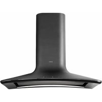
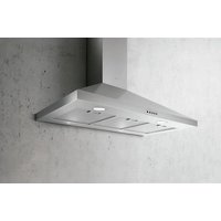
The hood has been made for use in the internal recirculating filtering version.
Cooking fumes and steam are aspirated inside the hood, filtered and cleaned, passing through the fat filter/s and the carbon filter/s that MUST be supplied with the hood.
Installation
Specialised personnel must carry out both the electrical and the mechanical installation.
Do not cut a joist or stud unless absolutely necessary. If a joist or stud must be cut, then a supporting frame must be constructed.
Fittings material is provided to secure the hood to most types of walls/ceilings.
However, a qualified technician must verify suitability of the materials in accordance with the type of wall/ceiling.
Before making cutouts, make sure there is proper clearance within the ceiling or wall for exhaust vent.
Hood installation height above cooktop is the users preference. The lower the hood is above the cooktop, the more efficient the capturing of cooking odors, grease and smoke.
CAUTION: FOR GAS RANGES INSTALLATION: MOUNT THIS HOOD SO THAT THE BOTTOM EDGE IS AT 30" (76,2 CM) ABOVE THE COOKING SURFACE. FOR ELECTRIC RANGES INSTALLATION: MOUNT THIS HOOD SO THAT THE BOTTOM EDGE IS NOT LESS THAN 24" (61 CM) AND NO MORE THAN 30" (76,2 CM) ABOVE THE COOKING SURFACE. HOUSEHOLD USE. PLEASE, READ INSTALLATION MANUAL FOR SPECIFIC APPLICATION.
Check your ceiling height and the hood height maximum before you select your hood.
Consult last pages of this manual for installation instruction and electrical connection steps.
Operation
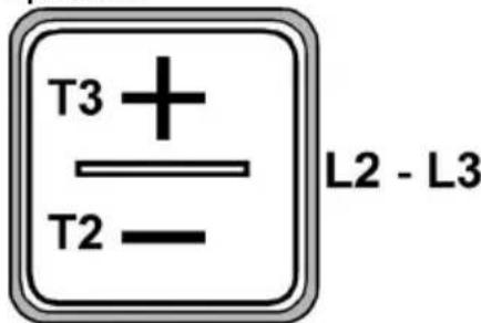
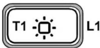
T1. Button ON/OFF lights
T2. Button to decrease suction speed (power) OFF 1: press repeatedly to decrease the speed until y turn off the hood OFF 2: at any speed press and hold for a longer time
T3. Button ON/to increasesuction speed (power) (1-2-3- Intensive)/Timer Intensive speed has a duration of approx. 5 minutes, then speed 3 is automatically set. To program the automatic switch-off (Timer) press and hold for a longer time; the shutoff time changes according to the set speed:
Speed 1: 20 minutes
Speed 2:15 minutes
Speed 3:10 minutes
Intensive speed: 5 minutes
Filter Saturation Indicator
The hood signals when necessary to perform filter maintenance:
Grease filter (every 40 hours of use): all LEDs with red light Activated charcoal odour filter (every 160 hours of operation): all LEDs with red light, LEDs L2 and L3 blink
Reset Filter Saturation
After performing filter maintenance, press and hold buttons T1 and T3, Leds L1, L2 and L3 blink briefly in red and then turn off for good.
Activation indicator for odour filter saturation with activated charcoal
This indicator is normally disabled. To enable it, proceed as follows:
With the hood off, press and hold simultaneously T1 and T2: L1 turns on first, then L2 and L3 and after that, when the buttons are released, the Leads L2 and L3 flash briefly to indicate successful activation.
Disabling the LED for charcoal filter
saturation: repeat the operation above; first the LEDs L1, L2 and L3 turn on simultaneously, then only L1, and after that, when the buttons are released, the leds L1, L2 and L3 turn on again to indicate successful disabling.
User Servicing and Maintenance Instructions
Cleaning
Clean using ONLY the cloth dampened with neutral liquid detergent. DO NOT CLEAN WITH TOOLS OR INSTRUMENTS. Do not use abrasive products. DO NOT USE ALCOHOL!
Steam screen
The steam screen must always be left closed and opened only for maintenance (e.g. cleaning or changing filters).
Fig. 12-15
Grease filter
Fig. 12-13-15
Traps cooking grease particles.
This must be cleaned once a month (or when the filter saturation indication system - if envisaged on the model in possession - indicates this necessity) using non aggressive detergents, either by hand or in the dishwasher, which must be set to a low temperature and a short cycle.
When washed in a dishwasher, the grease filter may discolor slightly, but this does not affect its filtering capacity.
Charcoal filter (filter version only)
Fig. 12-13-14-15
It absorbs unpleasant odors caused by cooking.
The charcoal filter can be washed once every two months (or when the filter saturation indication system - if envisaged on the model in possession - indicates this necessity) using hot water and a suitable detergent, or in a dishwasher at 65^ (if the dishwasher is used, select the full cycle function and leave dishes out).
Eliminate excess water without damaging the filter, then put it in the oven for 10 minutes at 100^ to dry completely. Replace the mattress every 3 years and when the cloth is damaged.
Replacing lamps
The hood is equipped with a lighting system based on LED technology.
The LEDs guarantee an optimum lighting, a duration up to 10 times as long as the traditional lamps and allow to save 90% electrical energy.
For replacement, contact the technical service.
LISEZ CES INSTRUCTIONS ET CONSERVEZ-LES
APPROVÉ POUR LES APPAREILS DE TYPE RÉSIDENTIEL
POUR UNE UTILISATION RÉSIDENTIELLE SEULEMENT
LISEZ CES INSTRUCTIONS ET CONSERVEZ-LES
VEUILLEZ LIRE CES INSTRUCTIONS AU COMPLET AVANT DE COMMENCER.
L'INSTALLATION DE L'APPAREIL DOIT RESPECTER TOUS LES CODES EN VIGUEUR.
- La National Fire Protection Association, Batterymarch Park Quincy, Massachusetts, 02269
** La CSA International, 8501 East Pleasant Valley Road, Cleveland, Ohio, 44131-5575
Vitesse 3:10 minutes
Vitesse intensive: 5 minutes
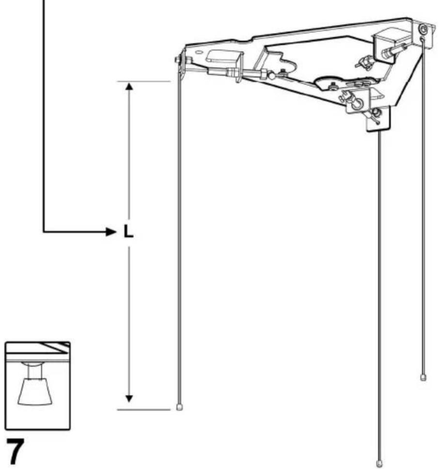
Note: Take into consideration the hood depth; the hood could be much deeper than the cooktop.
a. Mark center lines of cooktop or range on ceiling above. Use centerlines marked on ceiling to position the mounting template. Note location of hood front (that indicated with a printed arrow), side, and mounting holes indicated on template.
Note: Remember that printed arrow on template corresponds to front of the hood and consequently to side where control panels will be located at the end of installation).
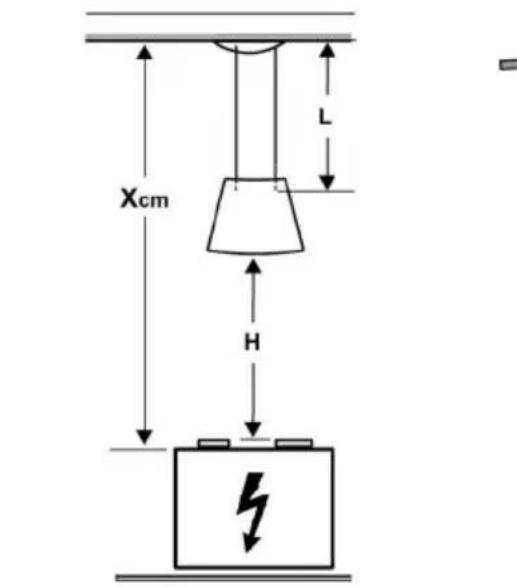
L () = X - H - 17 / 16'' (36cm)
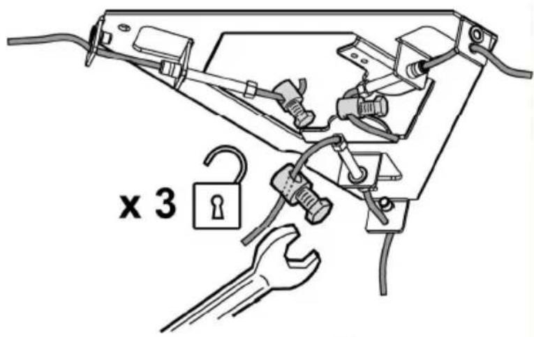
STOP! x 3
7
8
WARNING
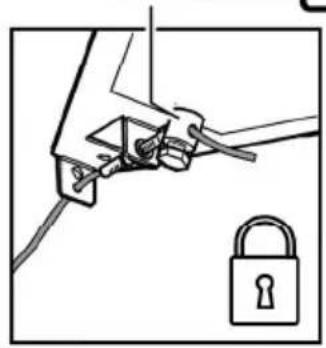
Electrical Shock Hazard
Warning: Turn off power circuit at the service panel before wiring this unit.
120 VAC, 15 or 20 Amp circuit required.
ELECTRICAL GROUNDING INSTRUCTIONS
THIS APPLIANCE IS FITTED WITH AN ELECTRICAL JUNCTION BOX WITH 3 WIRES, ONE OF WHICH (GREEN/YELLOW) SERVES TO GROUND THE APPLIANCE. TO PROTECT YOU AGAINST ELECTRIC SHOCK, THE GREEN AND YELLOW WIRE MUST BE CONNECTED TO THE GROUNDING WIRE IN YOUR HOME ELECTRICAL SYSTEM, AND IT MUST UNDER NO CIRCUMSTANCES BE CUT OR REMOVED.
Failure to do so can result in death or electrical shock.
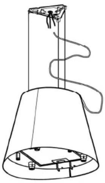
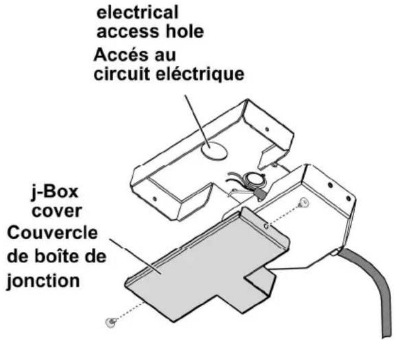
Remove the Junction box cover and install the conduit connector (cULus listed) in junction box.
AVERTISSEMENT
Electrical connection
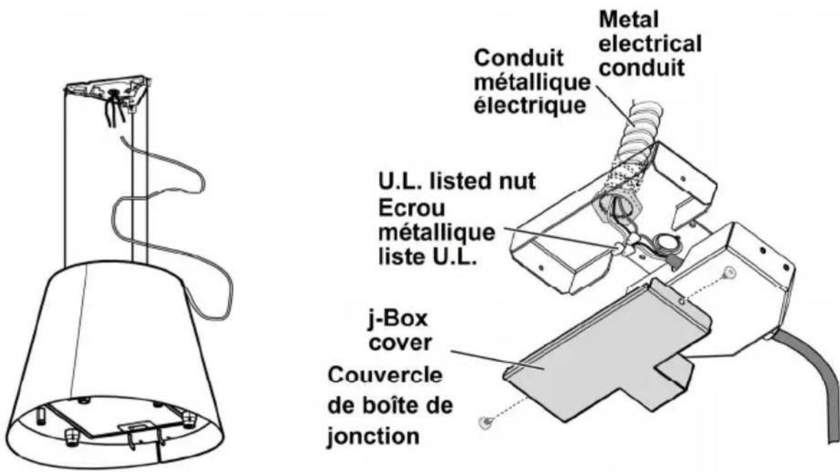
Run 3 wires; black, white and green, according to the National Electrical Code and local codes and ordinances, in 1/2 conduit from service panel to junction box. Connect black wire from service panel to black or red in junction box, white to white and green to green-yellow. Close and secure junction box cover.
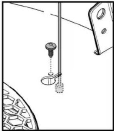
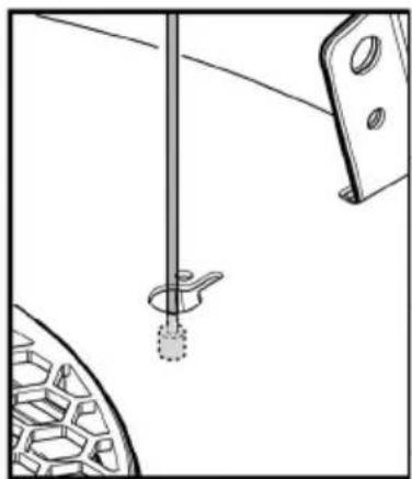
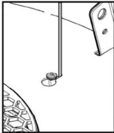
Fix the junction box to the support bracket on the ceiling with 2 screws.
Important! Replacement of the interconnection cable must be carried out by the authorised after-sales technical service.