DAC050BAUWDB - Air-conditioner DANBY - Free user manual and instructions
Find the device manual for free DAC050BAUWDB DANBY in PDF.

User questions about DAC050BAUWDB DANBY
0 question about this device. Answer the ones you know or ask your own.
Ask a new question about this device
Download the instructions for your Air-conditioner in PDF format for free! Find your manual DAC050BAUWDB - DANBY and take your electronic device back in hand. On this page are published all the documents necessary for the use of your device. DAC050BAUWDB by DANBY.
USER MANUAL DAC050BAUWDB DANBY
Owner's Use and Care Guide 1-10
- Welcome
- Important Safety Information
- Features
• Installation Instructions
• Operation Instructions
• Care and Maintenance - Troubleshooting
- Warranty
CLIMATISEUR
Read and follow all safety rules and operating instructions before first use of this product.

PRÉCAUTION :
This product is factory equipped with a power supply cord that has a three-pronged grounded plug. It must be plugged into a mating grounding type receptacle in accordance with the National Electrical Code and applicable local codes and ordinances. If the circuit does not have a grounding type receptacle, it is the responsibility and obligation of the customer to exchange the existing receptacle in accordance with the National Electrical Code and applicable local codes and ordinances. The third ground prong should not, under any circumstances, be cut or removed. Never use the cord, the plug or the appliance when they show any sign of damage. Do not use your appliance with an extension cord unless it has been checked and tested by a qualified electrician or electrical supplier.

IMPORTANT - MÉTHODE POUR LA MISE À LA TERRE
Welcome to the Danby family. We are proud of our quality products, and we believe in dependable service, like you will find in this Owner's Use and Care Guide, and like you will receive from our friendly customer service department. Best of all, you will experience these values each and every time you use your Danby appliance. That is important, because your new appliance will be a part of your family for a long time.
For easy reference, we suggest you attach a copy of your sales slip/receipt to this page, along with the following information, located on the manufacturer's nameplate on the right side of the unit above the powercord.
Note the information below; you will need this information to obtain service under warranty.
NOTE: TO RECEIVE WARRANTY SERVICE YOU MUST PROVIDE A VALID PROOF OF PURCHASE.
NOTE: THIS UNIT IS NOT DESIGNED FOR "THROUGH-THE-WALL" INSTALLATION.
Model No:
Serial No:
Date Purchased:
NEED HELP?
Before you call for service, here are a few things you can do to help us serve you better:
Read this Owner's Use and Care Guide:
It contains instructions to help you use and maintain your appliance properly.
If you received a damaged appliance:
Immediately contact the retailer (or builder) that sold you the appliance.
Save time and money:
Check the Troubleshooting section at the end of the guide before calling. This section helps you solve common problems that may occur.
If you do need service, you can relax, knowing help is only a phone call away.

natural_image
Simple black-and-white icon of a telephone handset inside a circle (no text or symbols)1-800-26-Danby (1-800-263-2629)

WARNING
Improper connection of the grounding plug can result in risk of re, electric shock and/or injury to persons associated with the appliance. Check with a qualified service representative if in doubt that the appliance is properly grounded.
FOR YOUR SAFETY: Read these instructions carefully before operating the unit.
ELECTRICAL REQUIREMENTS
- All wiring must comply with local and national electrical codes and must be installed by a qualified electrician. If you have any questions regarding the following instructions, contact a qualified electrician.
- Check available power supply and resolve any wiring problems BEFORE installing and operating this unit.
- This 115V air conditioner uses 4.8 or less nameplate amps and may be used in any properly wired, general-purpose household receptacle. See Table 1 for the specifications for the individual branch circuit.
- For your safety and protection, this unit is grounded through the powercord plug when plugged into a matching wall outlet. If you are not sure whether your wall outlet is properly grounded, please consult a qualified electrician.
- The wall outlet must match the 3-prong plug on the service cord supplied with the unit. DO NOT use plug adapters. See Table 2 for receptacle and fuse information.
- The rating plate on the unit contains electrical and other technical data. The rating plate is located on the right side of the unit, above the powercord.
| TABLE 1 | |
| Suggested Individual Branch Circuit | |
| Nameplate Amps4.8 | *AWG Wire Size18 |
| AWG- American Wire Gauge*Based on copper wire at 60°C temperature rating | |
| TABLE 2 | |
| Receptacle and Fuse Types | |
| Rated Volts | 125 |
| Amps | 15 |
| Wall Outlet |  |
| Fuse Size | 15 |
| Time Delay Fuse (or Circuit Breaker) | Plug Type |
FOR YOUR SAFETY: Read these instructions carefully before operating the unit.
ENERGY SAVING TIPS
Your appliance is designed to be highly efficient in energy savings. Follow these recommendations for greater efficiency.
- Select a thermostat setting that suits your comfort needs and leave at that chosen setting.
- The air filter is very efficient in removing airborne particles. Keep the air filter clean at all times. (Usually cleaned every 2 weeks depending on indoor air quality.)
- Use drapes, curtains or shades to keep direct sunlight from penetrating and heating the room, but do not allow drapes or curtains to obstruct the air flow around the unit.
- Start your air conditioner before the outdoor air becomes hot, to avoid an initial period of discomfort while the unit is cooling the room.

FEATURES
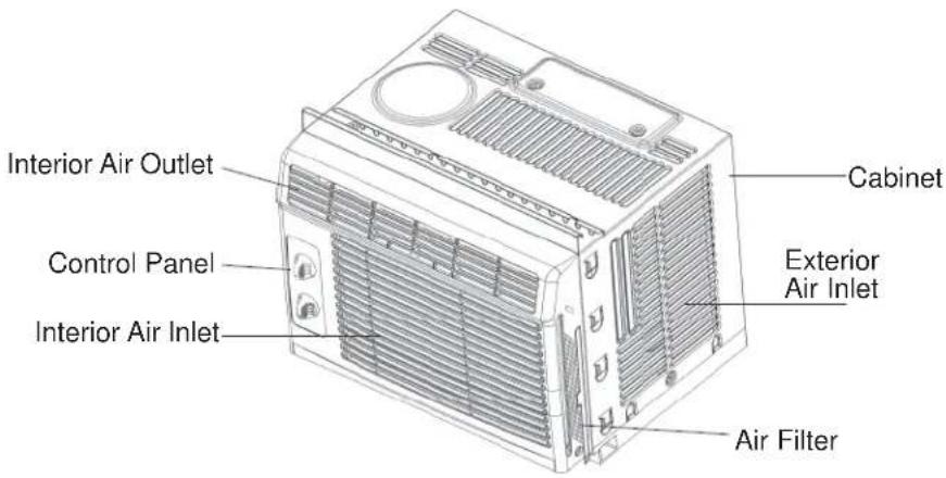
text_image
Interior Air Outlet Control Panel Interior Air Inlet Cabinet Exterior Air Inlet Air Filter
ELECTRIC SHOCK HAZARD
To avoid the possibility of personal injury, disconnect power to the unit before installing or servicing.
NOTE: Your Room Air Conditioner is designed for easy installation in a single or double-hung window. This unit is NOT designed for vertical (slider type) windows and/or through-the-wall applications.
TOOLS NEEDED FOR INSTALLATION:
- Screwdrivers: Phillips and fl at head.
• Power Drill: 1/8" (3.2mm) diameter drill bit - Pencil
- Measuring Tape
- Scissors
- Carpenter's Level
NOTE: Save the shipping carton and packing materials for future storage or transportation. From the carton, remove the plastic bag containing the installation hardware kit necessary for the installation of your air conditioner. Please check the contents of the hardware kit against the corresponding model check list, prior to installation of the unit. See Fig. 1.

CAUTION
Because the compressor is located on the controls side of the unit (left side), this side will be heavier and more awkward to manipulate. Inadequate support on control side of the unit can result in personal injury and damage to your unit and property. Therefore, it is recommended that you have someone assist you during the installation of this unit.
INSTALLATION HARDWARE
Fig. 1
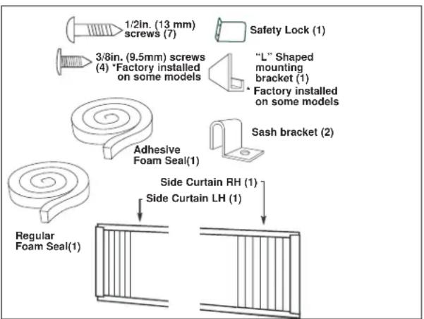
flowchart
graph TD
    A["1/2in. (13 mm) screws (7)"] --> B["3/8in. (9.5mm) screws (4) *Factory installed on some models"]
    B --> C[""L" Shaped mounting bracket (1)"]
    C --> D["Factory installed on some models"]
    D --> E["Sash bracket (2)"]
    E --> F["Adhesive Foam Seal(1)"]
    F --> G["Regular Foam Seal(1)"]
    G --> H["Side Curtain RH (1)"]
    H --> I["Side Curtain LH (1)"]
LOCATION
- This room air conditioner is designed to fit easily into a single or double hung window. However, since window designs vary, it may be necessary to make some modifications for safe, proper installation.
- Make sure window and frame are structurally sound and free from dry and rotted wood.
- For maximum efficiency, install the air conditioner on a side of the house or building which favours more shade than sunlight. If the unit is in direct sunlight, it is advisable to provide an awning over the unit.
- Provide sufficient clearance around the cabinet to allow for ample air circulation through the unit (See Fig. 2). The rear of the unit should be outdoors. It should not be in a garage, or inside a building. Keep unit as far away as possible from obstacles/obstructions and at least 30" above the floor or ground. Curtains and other objects within the room should be prevented from blocking the air flow.
- Be certain that the proper electrical outlet is within reach of the installation. Use only a single outlet circuit rated at 15 amps. All wiring should be in accordance with local and national electrical codes.
- DO NOT install unit where leakage of combustible gas is suspected. Your air conditioner may fail to operate in air containing oils (including machine oils), sulfide gas, near hot springs, etc.
NOTE: Your unit is designed to evaporate condensation under normal conditions. However, under extreme humidity conditions, excess condensation may cause basepan to overflow to the outside. The unit should be installed where condensation run-off cannot drip on pedestrians or neighbouring properties.
NOTE: It is normal for your unit to drip a small amount of water, especially on excessively humid days.
Fig. 2
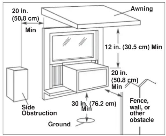
text_image
20 in. (50.8 cm) Min Awning 12 in. (30.5 cm) Min 20 in. (50.8 cm) Min Side Obstruction Ground 30 in. (76.2 cm) Min Fence, wall, or other obstacleASSEMBLY AND INSTALLATION
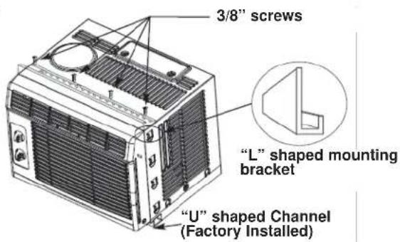
- Assembly of the upper channel to the cabinet (factory installed on some units).
- "L" Shaped Top Channel: install the "L" shaped channel to the top of the cabinet as shown in Fig. 3, using four (4) 3/8" screws.
-
Assembly of the side curtains to the cabinet.
-
Extend the shutter from the shutter frame and slide it into the shutter tabs on the side channel of the air conditioner, as shown in Fig. 4.
- Slide the shutters into the top ("L" shaped) and bottom ("U" shaped) channels. The shutters are identified (on frame) as left and right.
Fig. 3
text_image
3/8" screws "L" shaped mounting bracket "U" shaped Channel (Factory Installed)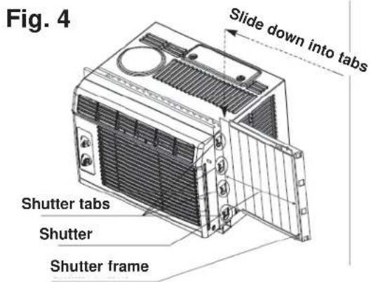
text_image
Fig. 4 Slide down into tabs Shutter tabs Shutter Shutter frame-
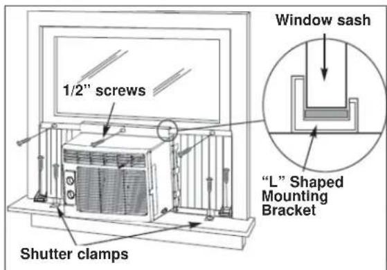
Completing the installation.
-
Carefully place the air conditioner into the window with the "L" shaped mounting bracket (on top) positioned in front of the upper window sash. The bottom of the cabinet should be positioned on the "recessed" portion of the window frame. Pull the window down until it rests just behind the front flange of the (top) "L" shaped mounting bracket (See Fig. 5).
- Expand the shutter frames (fully) on each side and secure the top of the frames to the window sash using one 1/2" screw on each side and one in the "L" shaped mounting bracket (Fig. 5).
- Secure the shutter clamp on each side of the lower part of the shutter, and secure to window sill using one 1/2" screw on each side (Fig. 5).
- Place the second foam sealing strip to fit the opening between the inside and outside windows, then attach the safety lock to the outside window frame using one 1/2" screw (See Fig. 6).
PLEASE NOTE: Window applications come in a variety of different styles. Therefore, it may be necessary to modify your particular installation.
text_image
1/2" screws Shutter clamps Window sash "L" Shaped Mounting Bracket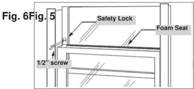
text_image
Fig. 6Fig. 5 Safety Lock Foam Seal 1/2" screw
OPERATING INSTRUCTIONS
ASSEMBLY AND INSTALLATION
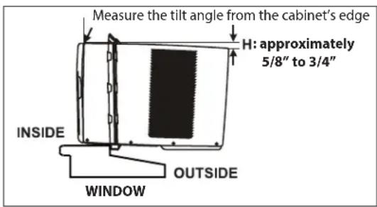
Check that the air conditioner is tilted downwards to the outside, about 3^ to 4^ , as shown in Fig. 7. After proper installation, condensed water should not drain from the overflow drain hole during normal use. If you notice water leaking out, check the angle of tilt, and make any necessary adjustments. However, on a very humid day, water leakage can occur – this is normal.
Measure the tilt angle from the cabinet's edge. The distance H should be approximately 5/8" to 3/4".
CONTROLS
Fig. 7
text_image
Measure the tilt angle from the cabinet's edge H: approximately 5/8" to 3/4" INSIDE OUTSIDE WINDOWFAN SPEEDS:
- LOW FAN will circulate air at minimum speed without cooling.
• HIGH FAN 🌐 will circulate air at maximum speed without cooling.
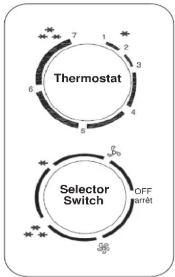
SELECTOR SWITCH: The selector switch controls cooling mode. Simply rotate the SELECTOR knob to one of the two settings described below.
COOLING MODES:
- LOW COOL ✱ provides cooling with minimum air circulation. Recommended for night-time use.
- HIGH COOL ✦ provides cooling with maximum air circulation. Recommended for quick cooling or for extremely hot days. Once room is cooled, reduce setting to LOW COOL.
• OFF shuts the unit down completely.
NOTE: Always allow 3 minutes before switching from one mode to another.
THERMOSTAT: The thermostat automatically controls the (compressor) cooling cycle and maintains the selected room temperature. To set the thermostat, rotate the thermostat knob to the desired cooling setting (1 warmest - 7 coldest).

IMPORTANT
Turn the selector switch slowly, allowing the unit to adjust. When using THERMOSTAT, be sure to allow three minutes before changing the temperature. Adjusting too quickly may cause compressor to overload.

IMPORTANT
Control panel may not be exactly as shown. Panel can vary depending on model purchased.
flowchart
graph TD
    A["Thermostat"] --> B["6"]
    B --> C["5"]
    C --> D["4"]
    D --> E["3"]
    E --> F["2"]
    F --> G["1"]
    G --> H["7"]
    I["Selector Switch"] --> J["OFF arrêt"]
    J --> K["3"]
    K --> L["2"]
    L --> M["1"]
    M --> N["0"]
CLEANING

NOTE: In order to avoid electric shock, please turn off the A/C and unplug the plug before maintenance or repair.
When cleaning the air conditioner be sure to turn the SELECTOR knob to the “OFF” position and disconnect the power cord from the electrical outlet.
- DO NOT use gasoline, benzene, thinner, or any other chemicals to clean this unit, as these substances may cause damage to the fi nish and deformation of plastic parts.
- Never attempt to clean the unit by pouring water directly over any of the surface areas, as this will cause deterioration of electrical components and wiring insulation.
AIR FILTER
If the air filter becomes clogged with dust, air flow is obstructed and reduces efficiency. The air filter should be cleaned every 2 weeks.
AIR FILTER REMOVAL:
The air filter is located behind the air intake front grill. To remove the air filter, grasp the filter handle on the front of the grill and slide it out to the right.
To reinstall the air filter, reverse the above procedures. The air filter must be vacuumed or washed by hand in warm water. Dry thoroughly before re-installing.
CLEANING AIR FILTER:
- Use a vacuum cleaner with soft brush attachment.
- Wash the filter in lukewarm water below 40^ C ( 104^ F). To get best results, wash with soapy water or a neutral cleaning agent.
- Rinse the filter with clean water and dry thoroughly before re-installing.

IMPORTANT
DO NOT forget to install the air filter. If the air conditioner is left to operate without the air filter, dust is not removed from the room air and may result in machine failure. When the air inlet grill and cabinet are dirty, wipe with lukewarm water (below 40^ C / 104^ F). Use of a mild detergent is recommended.
END OF SEASON CARE
- Turn off power and remove plug from wall socket.
- Clean filter.
- Store (covered) air conditioner in a dry location.

CAUTION
When installing and/or removing the air conditioner from the window, ensure that caution is taken to prevent it from falling backward. It is recommended that installation or removal of the air conditioner is done with assistance, to prevent injury to persons or damage to the unit or property.
DISPOSAL
Check for local regulatory compliance regarding the approved and safe disposal of this appliance.
Occasionally, a minor problem may arise, and a service call may not be necessary- use this troubleshooting guide for a possible solution. If the unit continues to operate improperly, call an authorized service depot or Danby's Toll Free Number for assistance.
Tel: 1-800-26-Danby ^® (1-800-263-2629)
| PROBLEM POSSIBLE CAUSE SOLUTION | ||
| Air conditioner will not operate • No | power to the unit • Check connection of | power cordto power source.Check fuse or circuit breaker.Set SELECTOR SWITCH toposition other than “OFF”. Thepower cord “RESET” button mustalways be pushed in (engaged)for correct operation. |
| Inefficient or no cooling | Dirty air filterUnit size inappropriate for appli-cationBlocked air flowPower interruption, settingschanged too quickly, or compres-sor overload tripped | Clean/replace air fi lterCheck with dealer to determineproper unit capacity for applicationRemove obstruction from grill oroutdoor louvresTurn the unit off and wait 5 min-utes before attempting to restart |
| Noisy unit • Loose parts | Inadequate support | Tighten loose partsProvide additional support to unit |
| Odors • Formation of mold, mildew, or | algae on wet surfaces | Clean unit thoroughlyPlace algaecide tablet in base pan |
| Water dripping outside • Hot and hum | mid weather • Condensation run-off is normalunder these conditions. | |
| Water dripping inside • Unit is not pro | perly angled toallow water to drain outsideIt is an extremely humid day | Unit must be installed on an anglefor proper condensation run-off.Check the unit and make anyadjustments.On an extremely humid day, thiseffect is expected. No actionrequired. |
| Ice or frost build-up | Low outside temperatureUnit air fi lter is dirty | When outdoor temperature isapproximately 18.3°C (65°F) orbelow, frost may form when unit isin cooling mode.Remove and clean fi lter |
NOTES:
- If circuit breaker is tripped repeatedly, or fuse is blown more than once, contact a qualified technician.
- When the unit is installed using proper installation steps, the unit is properly tipped toward the outdoors to allow for condensation run-off.
LIMITED APPLIANCE WARRANTY
This quality product is warranted to be free from manufacturer's defects in material and workmanship, provided that the unit is used under the normal operating conditions intended by the manufacturer.
This warranty is available only to the person to whom the unit was originally sold by Danby Products Limited (Canada) or Danby Products Inc. (U.S.A.) (hereafter "Danby") or by an authorized distributor of Danby, and is non-transferable.
TERMS OF WARRANTY
Plastic parts, are warranted for thirty (30) days only from purchase date, with no extensions provided.
First Year
During the first twelve (12) months, any functional parts of this product found to be defective, will be repaired or replaced, at warrantor's option, at no charge to the ORIGINAL purchaser.
To obtain service
It will be the consumer's responsibility to transport the appliance (at their own expense) to the original retailer (point of purchase) or a service depot for repair. Contact your dealer from whom your unit was purchased, or contact your nearest authorized Danby service depot, where service must be performed by a qualified service technician. If service is performed on the unit by anyone other than an authorized service depot, or the unit is used for commercial application, all obligations of Danby under this warranty shall be void.
Nothing within this warranty shall imply that Danby will be responsible or liable for any spoilage or damage to food or other contents of this appliance, whether due to any defect of the appliance, or its use, whether proper or improper.
EXCLUSIONS
Save as herein provided, by Danby, there are no other warranties, conditions, representations or guarantees, express or implied, made or intended by Danby or its authorized distributors and all other warranties, conditions, representations or guarantees, including any warranties, conditions, representations or guarantees under any Sale of Goods Act or like legislation or statute is hereby expressly excluded. Save as herein provided, Danby shall not be responsible for any damages to persons or property, including the unit itself, howsoever caused or any consequential damages arising from the malfunction of the unit and by the purchase of the unit, the purchaser does hereby agree to indemnify and hold harmless Danby from any claim for damages to persons or property caused by the unit.
GENERAL PROVISIONS
No warranty or insurance herein contained or set out shall apply when damage or repair is caused by any of the following:
1) Power failure.
2) Damage in transit or when moving the appliance.
3) Improper power supply such as low voltage, defective house wiring or inadequate fuses.
4) Accident, alteration, abuse or misuse of the appliance such as inadequate air circulation in the room or abnormal operating conditions (extremely high or low room temperature).
5) Use for commercial or industrial purposes (ie. If the appliance is not installed in a domestic residence).
6) Fire, water damage, theft, war, riot, hostility, acts of God such as hurricanes, floods etc.
7) Service calls resulting in customer education.
8) Improper Installation (ie. Building-in of a free standing appliance or using an appliance outdoors that is not approved for outdoor application).
Proof of purchase date will be required for warranty claims; so, please retain bill of sale. In the event warranty service is required, present this document to our AUTHORIZED SERVICE DEPOT.
Warranty Service
Carry-In
Danby Products Limited
PO Box 1778, Guelph, Ontario, Canada N1H 6Z9
Telephone: (519) 837-0920 FAX: (519) 837-0449
1-800-263-2629
07/13
Danby Products Inc.
PO Box 669, Findlay, Ohio, U.S.A. 45840
Telephone: (419) 425-8627 FAX: (419) 425-8629
BIENVENUE
natural_image
Simple black-and-white icon of a telephone handset inside a circle (no text or symbols)1-800-26-Danby (1-800-263-2629)

AVERTISSEMENT :
Danby Products Limited
PO Box 1778, Guelph, Ontario, Canada N1H 6Z9
Téléphone: (519) 837-0920 Télécopieur: (519) 837-0449
1-800-263-2629
03/14
Danby Products Inc.
PO Box 669, Findlay, Ohio, U.S.A. 45840
Téléphone: (419) 425-8627 Télécopieur: (419) 425-8629
NOTES / REMARQUES :
AIR CONDITIONER CLIMATISEUR
All repair parts are available for purchase or special order when you visit your nearest service depot. To request service and/or the location of the service depot nearest you, call the TOLL FREE number.
When requesting service or ordering parts, always provide the following information:
- Product Type
- Model Number
- Part Number
- Part Description