
22602 - Stump grinder TORO - Free user manual and instructions
Find the device manual for free 22602 TORO in PDF.




| Product Type | Stump Grinder |
| Brand | Toro |
| Model | 22602 |
| Engine | Honda GX390QXC9, 13 hp |
| Idle Speed | 1,250 to 1,550 rpm |
| Spark Plug | NKG BPR6ES (or equivalent) |
| Fuel Tank Capacity | 6.5 liters (1.72 US gallons) |
| Fuel Type | Unleaded gasoline (octane rating 87 or higher) |
| Engine Crankcase Capacity | 2 liters (2.1 quarts) |
| Recommended Engine Oil | SAE 10W-30, API SJ class or higher |
| Tires | 13 x 5.00 - 6 |
| Brakes | Disc, direct lever control (parking brake) |
| Drive Belt | Double band, section 3V |
| Clutch | Centrifugal |
| Cutting Teeth | 12, tungsten carbide tips |
| Cutting Depth | Approximately 30.48 cm (12 inches) |
| Dimensions (L x W x H) | 193 cm x 75 cm x 107 cm |
| Weight | 109 kg (240 lb) |
| Hour Meter | Yes, activates with engine running |
| Safety Devices | Safety bar, parking brake, blade guard, emergency stop by releasing the bar |
| Maximum Recommended Slope | 10 degrees |
| Routine Maintenance | Check oil, air filter, belt, blade, lubricate bearings every 10 hours |
| Warranty | 2 years (Kohler engine: 3 years), detailed conditions in the manual |
| Repairability | Original Toro parts available at authorized dealers |
Frequently Asked Questions - 22602 TORO
User questions about 22602 TORO
0 question about this device. Answer the ones you know or ask your own.
Ask a new question about this device
Download the instructions for your Stump grinder in PDF format for free! Find your manual 22602 - TORO and take your electronic device back in hand. On this page are published all the documents necessary for the use of your device. 22602 by TORO.
USER MANUAL 22602 TORO
Model No. 22602-Serial No. 310000001 and Up
Introduction
Warning
CALIFORNIA
Proposition 65 Warning
The engine exhaust from this product contains chemicals known to the State of California to cause cancer, birth defects, or other reproductive harm.
[Non-Text]
There may be buried power, gas, and/or telephone lines in the work area. Shock or explosion may occur if you dig into them.
Have the property or work area marked for buried lines and do not dig in marked areas. Contact your local marking service or utility company to have the property marked (for example, in the United States, call 811 for the nationwide marking service).
Because in some areas there are local, state, or federal regulations requiring that a spark arrester be used on the engine of this machine, a spark arrester is available as an option. If you require a spark arrester, contact your Authorized Toro Service Dealer.
Genuine Toro spark arresters are approved by the USDA Forestry Service.
Important: It is a violation of California Public Resource Code Section 4442 to use or operate the engine on any forest-covered, brush-covered, or grass-covered land without a spark arrester muffler maintained in working order, or the engine constricted, equipped, and maintained for the prevention of fire. Other states or federal areas may have similar laws.
This spark ignition system complies with Canadian ICES-002.
Important: The enclosed Engine Owner's Manual is supplied for information regarding the US Environmental Protection Agency (EPA) and the California Emission Control Regulation of emission systems, maintenance, and warranty. Replacements may be ordered through the engine manufacturer.
The Stump Grinder is used to remove tree stumps. By moving the machine in sweeping movements laterally over the top and front of the stump, the blade gradually grinds it away. Only use the machine for removing tree stumps and exposed root systems. It is not intended for any other use. Read this information carefully to learn how to operate and maintain your product properly and to avoid injury and product damage. You are responsible for operating the product properly and safely.
You may contact Toro directly at www.Toro.com for product and accessory information, help finding a dealer, or to register your product.
Whenever you need service, genuine Toro parts, or additional information, contact an Authorized Service Dealer or Toro Customer Service and have the model and serial numbers of your product ready. Figure 1 identifies the location of the model and serial numbers on the product. Write the numbers in the space provided.
![TORO 22602 - [Non-Text] - 1](/content/2026/04/672027/images/507135e945137dd5702b5e72a64b0d6c613a6fc4c41b0068d38108b36f8dc3a1.jpg)
natural_image
Technical line drawing of a mechanical pump or scrubber assembly (no text or symbols)Figure 1
1. Model and serial number location
Model No. ____
Serial No. ____
This manual identifies potential hazards and has safety messages identified by the safety alert symbol (Figure 2), which signals a hazard that may cause serious injury or death if you do not follow the recommended precautions.
![TORO 22602 - [Non-Text] - 2](/content/2026/04/672027/images/3c1dc83f34feba0c34f3c026133d889dbbde14446e7a1f869f6262c556997cee.jpg)
Figure 2
1. Safety alert symbol
Contents
Introduction......1
Safety....4
Safe Operating Practices ....4
Training 4
Preparation 4
Operating 5
Slope Operation 6
Maintenance and Storage ......6
Safety and Instructional Decals ......8
Controls....9
Throttle 9
Safety Bail 9
Parking Brake 9
Hour Meter 9
Specifications....10
Operating......11
Before you Start ....11
Adding Fuel ......12
Using Stabilizer/Conditioner ....13
Filling the Fuel Tank 13
Checking the Engine Oil Level .....14
Starting and Stopping the Engine .....15
Starting the Engine 15
Stopping the Engine ....16
Grinding the Stump ......16
Maintenance ....19
Recommended Maintenance Schedule ..19
Cleaning the Cyclone Air Filter .....20
Replacing the Air Filter 21
Changing the Engine Oil 23
Changing the Oil 23
Cleaning the Sediment Cup ......24
Servicing the Spark Plug ....25
Removing the Spark Plug 25
Installing the Spark Plug ....25 Cutting Blade ....26
Replacing Cutting Blades .....26
Parking Brake Adjustment ....27
Cleaning and Washing 27
Lubricating the Bearings ....27 Drive Belt ....28
Belt Drive Adjustment ......28
Storage 29
Troubleshooting ....30
Warranty ...... Back Cover
Safety
Improper use or maintenance by the operator or owner can result in injury. To reduce the potential for injury, comply with these safety instructions and always pay attention to the safety ⚠alert symbol, which means: Caution, Warning, or Danger—personal safety instruction. Failure to comply with the instruction may result in personal injury or death.
Safe Operating Practices
This product is capable of amputating hands and feet. Always follow all safety instructions to avoid serious injury or death.
WARNING
Engine exhaust contains carbon monoxide, an odorless deadly poison that can kill you. Do not run the engine indoors or in an enclosed area.
Training
- Read the Operator's Manual and other training material. If the operator(s) or mechanic(s) can not read English, it is the owner's responsibility to explain this material to them.
- Become familiar with the safe operation of the equipment, operator controls, and safety signs.
- All operators and mechanics should be trained. The owner is responsible for training the users.
- Never let children or untrained people operate or service the equipment. Local regulations may restrict the age of the operator.
- The owner/user can prevent and is responsible for accidents or injuries occurring to himself or herself, other people or property.
Preparation
- Inspect the area where the equipment is to be used and remove all objects such as rocks, toys, and wire which can be thrown by the machine.
-
Use extra care when handling gasoline and other fuels. They are flammable and vapors are explosive.
-
Use only an approved container
- Never remove the gas cap or add fuel with the engine running. Allow the engine to cool before refueling. Do not smoke.
- Never refuel or drain the machine indoors.
- Check that the operator presence controls, safety switches, and shields are attached and functioning properly.
- Check that the cutting blade stop rotating when you reduce the throttle.
- Do not operate unless all safety devises are attached and functioning properly.
- Wear appropriate clothing including hardhat, safety glasses, long pants, safety shoes, and hearing protection. Long hair, loose clothing or jewelry may get tangled in moving parts.
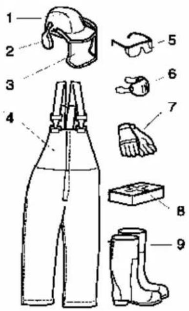
You require the following personal protective equipment:
- Protective helmet (hard hat)
- Ear protection
- Face guard
- Protective trousers
- Protective glasses
- Breathing protection (risk of dusty work environment)
- Protective gloves
- First aid kit
- Protective boots or steel-toed shoes.
Operation
- Never run an engine in an enclosed area.
- Only operate in daylight, keeping away from holes and hidden hazards.
- Be sure the parking brake is engaged before starting the engine. Only start the engine from the operator's position.
- Never operate with the guards not securely in place. Be sure all interlocks are attached, adjusted properly, and functioning property.
- Do not change the engine governor setting or over speed the engine.
- Engage the parking brake and shut off the engine before leaving the operator's position for any reason.
- Keep hands and feet away from moving blades.
• Make sure you have a proper foothold when using the machine, particularly when backing. - Walk, don't run when moving machine on location.
- Never work on wet grass. Poor traction may cause you to slip.
- Look behind and down before backing up to be sure of a clear path.
- Keep pets and bystanders away.
- Do not operate the machine under the influence of alcohol or drugs.
- Use care when loading or unloading the machine into a trailer or truck.
- Use care when approaching blind corners, shrubs, trees, or other objects that may obscure vision.
- Ensure that the area is clear of other people before operating the unit. Stop the unit if anyone enters the area.
- Never leave a running unit unattended. Always stop the engine, set the parking brake, before leaving.
- Watch for traffic when operating near or crossing roadways.
- Do not touch parts which may be hot from operation. Allow them to cool before attempting to maintain, adjust, or service.
- Only operate the unit in areas where there is sufficient clearance for the operator to safely maneuver the product.
- Before removing a stump, have the area marked for underground utilities, and do not dig in marked areas.
- Locate the pinch point areas marked on the unit and keep hands and feet away from these areas.
- Lightning can cause severe injury or death. If lightning is seen or thunder is heard in the area, do not operate the machine; seek shelter.
Slope Operation
Slopes are a major factor related to loss-of-control and accidents, which can result in severe injury or death. All slopes require extra caution.
- Do not operate the unit on hillsides or slopes exceeding 10 degrees.
- Remove obstacles such as rocks, tree limbs, etc. from the work area. Watch for holes, ruts, or bumps, as uneven terrain could overturn the unit. Tall grass can hide obstacles.
- Keep all movements on slopes slow and gradual. Do not make sudden changes in direction.
- Do not operate near drop-offs, ditches, or embankments. The unit could suddenly turn over if a wheel goes over the edge of a cliff or ditch, or if an edge caves in.
- Do not operate on wet grass. Reduced traction could cause sliding.
Maintenance and Storage
- Set the parking brake, stop the engine. Wait for all movement to stop before adjusting, cleaning, or repairing.
- Clean debris from unit, drives, mufflers, and engine to help prevent fires. Clean up oil or fuel spillage.
- Let the engine cool before storing and do not store near flame.
- Do not store fuel near flames or drain indoors.
- Park the machine on level ground. Never allow untrained personnel to service the machine.
- Carefully release pressure from components with stored energy.
- Remove the spark plug wire before making any repairs
- Keep hands and feet away from moving parts. If possible, do not make adjustments with the engine running.
- Keep all parts in good working condition and all hardware tightened. Replace all worn or damaged decals.
- Keep nuts and bolts tight. Keep equipment in good condition.
- Never tamper with safety devices.
- Keep the unit free of grass, leaves, or other debris build-up. Clean up oil or fuel spillage. Allow the unit to cool before storing.
-
Use extra care when handling gasoline and other fuels. They are flammable and vapors are explosive.
-
Use only an approved container.
- Never remove the gas cap or add fuel when the engine is running. Allow the engine to cool before refueling. Do not smoke.
- Never refuel the unit indoors.
- Never store the unit or fuel container inside where there is an open flame, such as near a water heater or furnace.
- Never fill a container while it is inside a vehicle, trunk, pick-up bed, or any surface other than the ground.
- Keep container nozzle in contact with the tank during filling.
- Close the fuel valve for storage or transport
- Stop and inspect the equipment if you strike an object. Make any necessary repairs before restarting.
- Use only genuine Toro replacement parts to ensure that original standards are maintained.
Safety and Instructional Decals

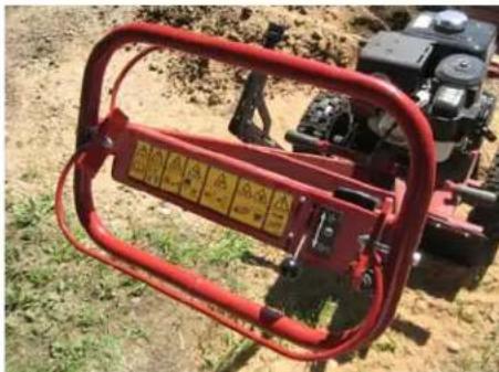
Safety decals and instructions are easily visible to the operator and are located near any areas of potential danger. Replace any decal that is damaged of lost.

119-4701
- Warning - Read Operator's Manual
- Warning - Train all product users
- Thrown objects - Keep bystanders away
- Thrown objects - Wear hard hat and safety glasses, clean area of debris
- Rotating belt - Keep guard in place
- Explosion and electric shock hazard
- Call utilities to mark underground hazards
- Warning - Stop engine before performing maintenance operations
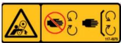
117-4979
- Rotating belt - Keep guard in place
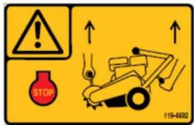
119-4692
- Warning - Stop engine before lifting
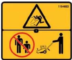
119-4693
- Thrown objects - Keep by-standers away

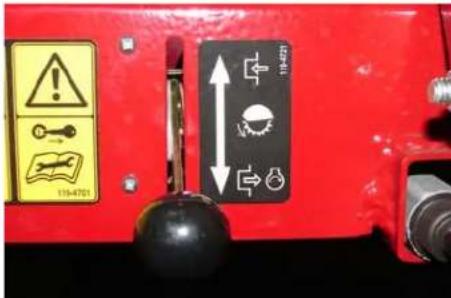
119-4721
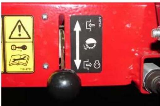
- Move throttle to engage/disengage blade
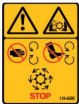
119-4690
- Warning, - Rotating blade
- Keep and hands and feet clear
- Stop rotating blade before servicing
Controls
Throttle:
The throttle lever controls engine speed.
With the lever down, in the DISENGAGED position the engine runs at idle. This is also the starting position.
When the engine speed increases, to the ENGAGED position, the centrifugal clutch engages and the cutting blade rotates.
Safety Bail:
Hold the safety bail against the handle to deactivate the engine kill switch so the engine will start. Releasing the bail stops the engine.
natural_image
Red agricultural machine with attached metal frame, no visible text or symbols on the device itselfParking Brake:
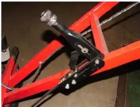
The parking brake holds the left wheel from turning to secure the machine and for easy movement of the machine from side to side when grinding the stump.
natural_image
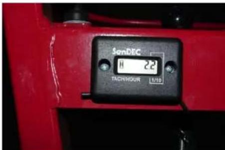
Close-up of a red mechanical frame with black clamps and bolts, no visible text or symbolsHour Meter:
The hour meter shows the hours the unit has been used and runs only when the engine is running.
Specifications
| Model | 22602 |
| Engine | Honda GX390QXC9 |
| Idling speed | 1250-1550 RPM |
| Spark plug | NKG BPR6ES |
| Fuel tank volume | 6.5 liters/1.72 US Gal |
| Tires | 13 x 5.00 - 6 (pneumatic) |
| Brake | Disk - Lever activated Direct |
| Drive Belt | Double-banded - 3V section |
| Clutch | Centrifugal clutch |
| Cutters | 12 - Tungsten carbide tips |
| Cutting depth | Approx 12" (30.48 cm) |
| Length | 76" (193 cm) |
| Width | 29.5 (75 cm) |
| Height | 42" (107 cm) |
| Weight | 240 lbs. (109 kg) |
Operation
Note: Determine the left and right sides of the machine from the normal operating position.
Important: Before operating, check the fuel and oil level, and remove debris from the traction unit. Also, ensure that the area is clear of people and debris. You should also know and have marked the locations of all utility lines.
Before you start:
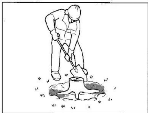
Dig away the earth and remove any stones near the tree stump that may interfere with your work. Check that the ground is free of foreign objects, such as electrical cables, barbed wire, etc.
Cut or trim the stump as necessary using a power saw.
Review all the machine's safety decals.
Use a hard-hat, hearing, and eye protection. A mesh visor alone does not provide sufficient eye protection; supplement with protective glasses.
Make sure that you are familiar with safety regulations and shutdown procedures described in the Operator's Manual.
Make sure that all guards are in place and in good condition.
Make sure that the blades and cutters are in place and in good condition.
Make sure that the work area, cutter, and stump in particular are free from metallic objects such as wire, nails, etc. that could be thrown out and injure persons in the vicinity and damage the equipment.
Make sure that everyone, including children and animals, maintain a distance of at least 50 feet (15 m) from the machine. Debris can be thrown out and injure people and animals.
natural_image
Line drawing of a person digging with a shovel, standing on a small pot (no text or symbols)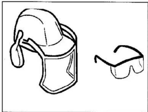
natural_image
Simple line drawing of a helmet and sunglasses (no text or symbols)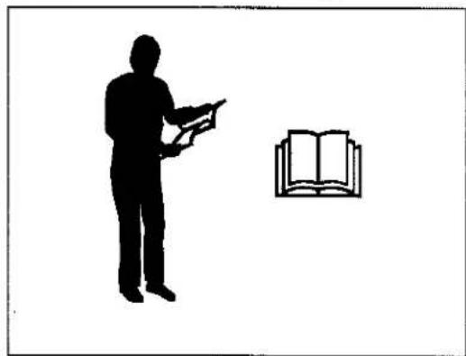
natural_image
Silhouette of a person holding an open book next to an open book (no text or symbols present)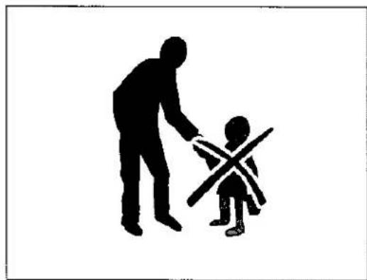
natural_image
Silhouette of an adult and a child interacting, with no text or symbols presentAdding Fuel
Use unleaded gasoline (87 pump octane minimum). Leaded, regular gasoline may be used if unleaded is not available.
DANGER
In certain conditions, gasoline is extremely flammable and highly explosive. A fire or explosion from gasoline can burn you and others and can damage property.
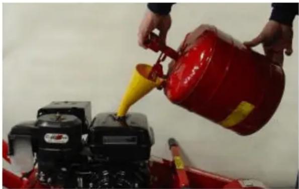
- Fill the fuel tank outdoors, in an open area, when the engine is cold. Wipe up any gasoline that spills.
- Never fill the fuel tank inside an enclosed trailer.
- Do not fill the fuel tank completely full. Add gasoline to the fuel tank until the level is below the bottom of the strainer neck. This empty space in the tank allows gasoline to expand.
• Never smoke when handling gasoline,
natural_image
Person pouring yellow liquid into a red fire extinguisher using a small machine (no visible text or symbols)and stay away from an open flame or where gasoline fumes may be ignited by a spark.
- Store gasoline in an approved container and keep it out of the reach of children. Never buy more than a 30-day supply of gasoline.
- Do not operate without entire exhaust system in place and in proper working condition.
DANGER
In certain conditions during fueling, static electricity can be released causing a spark which can ignite the gasoline vapors. A fire or explosion from gasoline can burn you and others and can damage property.
• Always place gasoline containers on the ground away from your vehicle before filling.
- Do not fill gasoline containers inside a vehicle or on a truck or trailer bed because interior carpets or plastic truck bed liners may insulate the container and slow the loss of any static charge.
- When practical, remove gas-powered equipment from the truck or trailer and refuel the equipment with its wheels on the ground.
- If this is not possible, then refuel such equipment on a truck or trailer from a portable container, rather than from a gasoline dispenser nozzle.
- If a gasoline dispenser nozzle must be used, keep the nozzle in contact with the rim of the fuel tank or container opening at all times until fueling is complete.
Important: Do not use methanol, gasoline containing methanol, or gasohol containing more than 10% ethanol because the fuel system could be damaged. Do not mix oil with gasoline.
Using Stabilizer/Conditioner
Use a fuel stabilizer/conditioner in the traction unit to provide the following benefits:
- Keeps gasoline fresh during storage of 90 days or less. For longer storage it is recommended that the fuel tank be drained.
• Cleans the engine while it runs - Eliminates gum-like varnish buildup in the fuel system, which causes hard starting
Important: Do not use fuel additives containing methanol or ethanol.
Add the correct amount of gas stabilizer/conditioner to the gas.
Note: A fuel stabilizer/conditioner is most effective when mixed with fresh gasoline. To minimize the chance of varnish deposits in the fuel system, use fuel stabilizer at all times.
Filling the Fuel Tank
- Park the traction unit on a level surface and stop the engine.
- Allow the engine to cool.
- Clean around the fuel tank cap and remove it.
Note: The cap is tethered to the fuel tank.
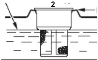
- Add unleaded gasoline to the fuel tank, until the level is just below the bottom of the strainer neck.
Important: This space in the tank allows gasoline to expand. Do not fill the fuel tank
completely full. 1
-
Maximum fuel level 2. Fuel tank top
-
Install the fuel tank cap securely, turning it until it clicks.
- Wipe up any gasoline that may have spilled.
Checking the Engine Oil Level
- Park the unit on a level surface and stop the engine.
- Clean around the oil dipstick
- Unscrew the oil dipstick and wipe the end clean.
- Slide the oil dipstick fully into the crankcase. Do not thread it in.
- Pull the oil dipstick out and look at the end. Oil should be to the top of the upper limit range.
Note: Running the engine with low oil level can cause engine damage. This type of damage is not covered by Warranty.
The engine is equipped with and Oil Alert system that will automatically stop the engine before the oil level falls below the safe limit. To avoid the inconvenience of an unexpected shutdown, fill to the upper limit, and check the oil level regularly.
1
natural_image
Mechanical assembly diagram showing a bracket with mounting holes and a connector (no text or symbols)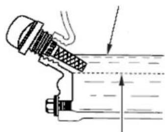
natural_image
Technical line drawing of a mechanical assembly with no visible text or symbols2
4
-
Oil dipstick 2. Oil fill hole 3. Upper limit 4. Lower limit
-
If the oil level is low, slowly pour only enough oil into crankcase to raise the level to the upper limit.
Important: Do not overfill the crankcase with oil because the engine may be damaged.
- Replace the oil dipstick.
Starting and Stopping the Engine
Starting the Engine
-
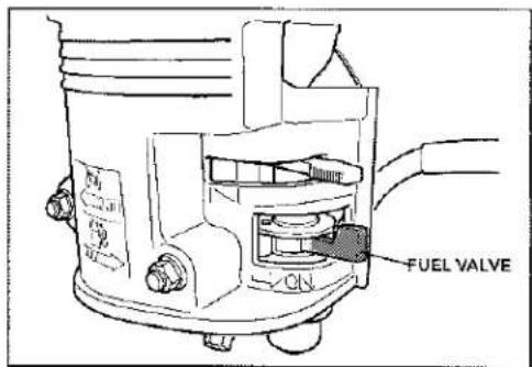
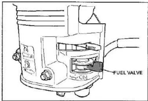
Move the fuel valve to the OPEN position, all the way to the right.
-
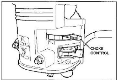
Move the choke lever left to the ON position if you are starting a cold engine.
Note: A warm or hot engine may not require choke.
-
Move the throttle to the DISENGAGE position.
-
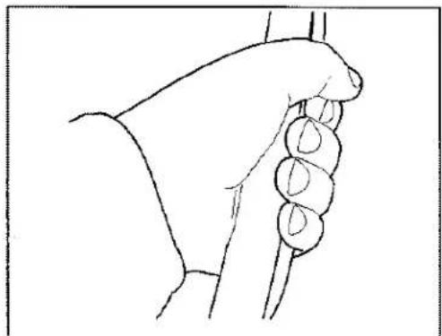
Hold the safety bail against the handle and push the handle down enough to raise the cutting wheel off the ground.
natural_image
Line drawing of a hand gripping a small object, possibly a tool or device (no text or symbols present)-
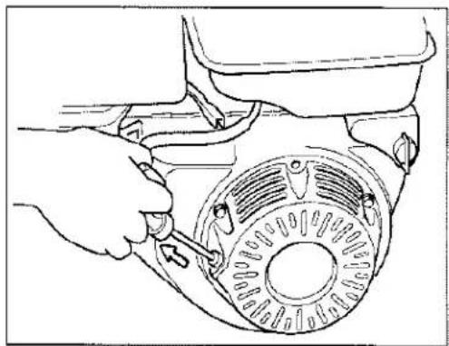
Pull the starter handle lightly until you feel resistance, then pull briskly in the direction the arrow show. Return the starter grip gently.
-
After the engine starts, gradually move the choke lever back to the OFF position. If the engine stalls or hesitates, move the choke back to the ON again until the engine warms up. Then move to the full OFF position.
natural_image
Line drawing of a hand adjusting a circular mechanical component with a tool (no text or symbols)Stopping the Engine
- Move the throttle to the DISENGAGE positions.
Note: If the engine has been working hard or is hot, let it run for a minute before releasing the safety bail. This helps to cool the engine before stopping. In an emergency, the engine may be stopped immediately.
- Release the safety bail to stop the engine.
- Move the fuel valve to the CLOSED position, all the way to the left.
Grinding a Stump
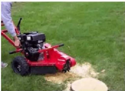
Place the stump grinder into position with cutting blade near the front-top edge of the stump.
WARNING
A rotating cutting blade is very DANGEROUS! Keep bystanders away from thrown debris.
Set the parking brake to the lock position.
natural_image
Red manual lawn mower on grass with a person operating it, no visible text or symbols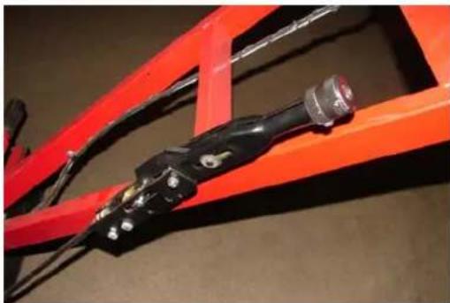
natural_image
Close-up of a red industrial frame with black components and wires, no visible text or symbols- Set throttle to the DISENGAGE position.
- Start the engine; refer to Starting the Engine.
- Allow engine to warm up at idle for two minutes.
- Push the handle down enough to raise the cutting wheel off the ground.
- Move throttle up to the ENGAGE position, this will engage the centrifugal clutch and the cutting blade rotates.
-
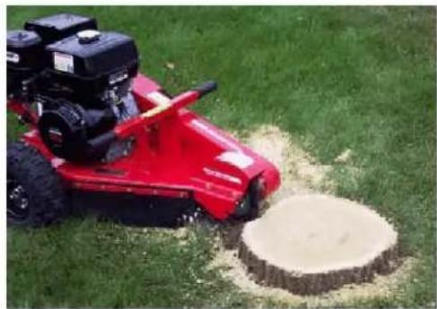
Swing the cutting blade to one side, then lower it approximately 1/2" to 1" into the front-top corner of the stump. Swing the cutting blade back and forth, lowering the cutting blade approximately 1/2" to 1" before each sweep, until you have removed the front portion of the stump to ground level.
-
Raise the cutting blade until center of cutting blade is just above top of the stump.
-
With the cutting blade off to one side, release the parking brake and advance the machine forward, reset the parking brake.
-
Sweep the cutting blade across the stump, cutting away 1/2" to 1" of stump.
-
Advance the machine forward 1/2" to 1", and sweep across the stump in the opposite direction.
-
Continue sweeping and cutting blade left and right across stump, advancing the machine before each sweep, cutting 1/2" to 1" depth of cut with each sweep.
-
Continue cutting until top level of stump is all removed, making sure not to cut stump deeper than ground level during this first stage.
-
Move throttle to the DISENGAGE position, push the handle down enough to raise the cutting wheel off the ground. Wait ten seconds for blade to stop rotating then release brake and retract machine from stump.
natural_image
Red lawn mower on grass with a circular tree stump nearby (no text or symbols visible)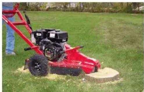
natural_image
Red lawn mower on a grassy field with a person standing nearby (no visible text or symbols)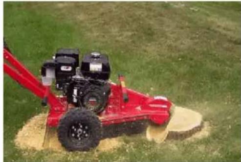
natural_image
Red agricultural machine operating on a grassy field with visible soil and equipment (no text or symbols)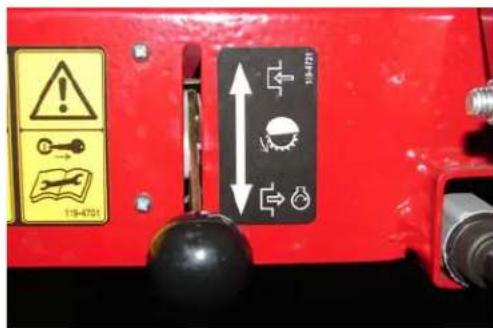
Pull machine away from stump, and rake chips away from stump.
-
Place stump machine into position with cutting blade near the front-top edge of the stump.
-
Set brake to the lock position.
-
Move the throttle up to the ENGAGE position.
-
Complete cutting stump by repeating step 12 again and again until entire stump is cut to desired depth.
-
Stop the machine; refer to Stopping the Engine.
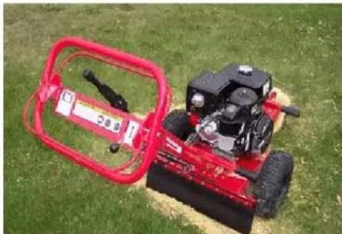
natural_image
Red agricultural machine with attached red frame on grassy field (no visible text or symbols)DO NOT let front of unit touch ground until you are sure cutting wheel has stopped turning.
WARNING
A rotating cutting blade is very DANGEROUS!
Stay at the operating position and be sure that the blade comes to a complete stop before doing anything else.
Maintenance
Recommended Maintenance Schedule
| Maintenance Service Interval | Maintenance Procedure |
| Before each use or daily | Check the engine oil level.Lubricate the cutting blade bearings. (Lubricate immediately after every washing.)Check the air filterCheck the safety bail switchCheck the cutter blades for sharpness and missing or bent teethInspect the drive belt for wear and tensionRemove debris from the unitCheck for loose fastenersCheck/replace safety and instructional decals |
| After the first 20 hours | Change the engine oil |
| Every 50 hours | Check/Replace the air filter (1)Inspect the drive belt for wear or damage |
| Every 100 hours | Change the engine oil (1)Clean the sediment cupCheck/adjust the spark plug |
| Every 300 hours | Replace the air filter paper elementReplace the spark plugsReplace the drive belt |
| Yearly or before storage | Change the engine oilCheck/Replace the air filterClean the sediment cupCheck/adjust the spark plugTouch up chipped paint |
(1) More frequently in dusty conditions
Important: Refer to your Engine Operator's Manual for additional maintenance procedures.
Cleaning the Cyclone Air Filter
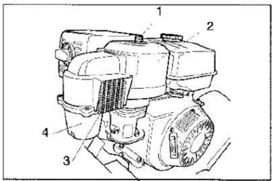
The cyclone air filter collects the largest contaminant particles, which collect in the container. When you can see a layer of dirt at the bottom of the container, the cyclone housing (4), air channels and air intake screen (3) must be cleaned.
- Remove the three screws holding the cyclone housing.
- Remove the housing with the air intake screen and remove the air channels.
Note: The air channels may remain in the upper portion or follow along with the housing when removed.
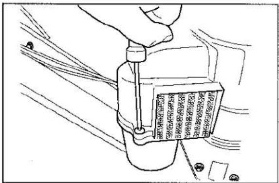
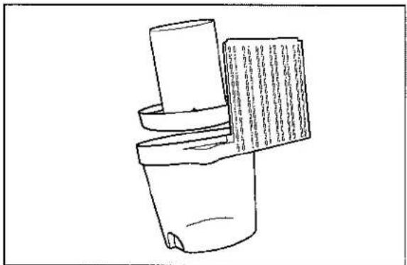
- Clean the components. Use water, detergent and a brush. Dry carefully.
- Place the air channels in the cyclone housing.
natural_image
Simple line drawing of a container with a lid and a paper sheet, no text or symbols present- Insert cyclone housing into position and make sure it fits in the upper portion. DO NOT use force; align it in place before fitting the screws.

natural_image
Line drawing of a hand adjusting a mechanical component with wires (no text or symbols)Replacing the Air Filter
If the engine is low on power, produces black smoke or runs unevenly, the air filter may be clogged. For this reason, it is important to clean and replace the air filter regularly (see the maintenance schedule for the proper service interval).
WARNING
Allow the exhaust system to cool before performing service. Risk for burns.
- Remove the wing nut (1) and lift off the cyclone filter with the air filter cowling (2).
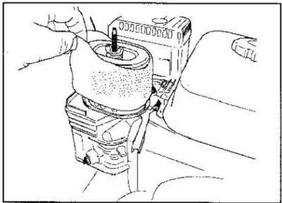
- Remove the foam pre-filter and clean using a mild detergent and water.
- Squeeze it dry with a clean cloth.
- Soak it with new engine oil. Wind the filter in an absorbent cloth and squeeze out excess oil.
natural_image
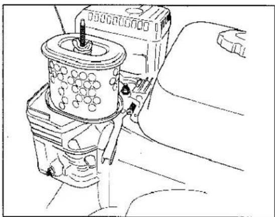
Technical line drawing of a mechanical assembly with no visible text or symbols- Remove the wing nut on top of the air filter and remove the paper filter.
natural_image
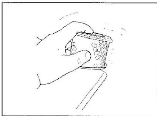
Technical line drawing of a mechanical device with no visible text or symbols- Tap the paper filter against a fixed surface to remove dust. If the paper filter is still dirty or damaged, replaced it.
Important: Do not us compressed air to blow out paper element, this can damage paper element.
Assemble the air filter as follows:
-
Mount the paper filter in the air filter housing and tighten the wing nut.
-
Position the foam pre-filter over the paper filter.
-
Install the cyclone filter with the air filter cover.
natural_image
Hand holding a small container with granular contents, no visible text or symbolsChanging the Engine Oil
Note: Change oil more frequently when operating conditions are extremely dusty.
Oil Type: Detergent oil with an API service rating of SJ, or higher.
Crankcase Capacity: 2.1 qt. (2 l)
Viscosity: SAE 10W-30 is recommended for general use. Other viscosities show in the chart may be used when the average temperature in your area is within the indicated range
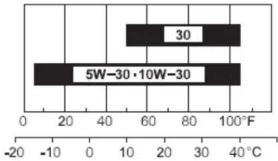
bar
| Category | Value (°C) | |---|---| | 30 | 60 | | 5W-30·10W-30 | 80 |AMBIENT TEMPERATURE
Changing the Oil
-
Start the engine and let it run for five minutes. This warms the oil so it drains better.
-
Park the unit so that the drain is slightly lower than the opposite side to ensure that the oil drains completely.
-
Set the parking brake and stop the engine.
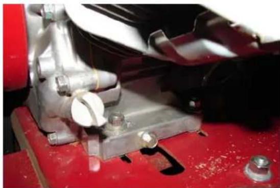
-
Remove the drain plug and catch oil drained through the slot in frame.
-
When the oil has drained completely, replace the plug.
natural_image
Close-up of a mechanical assembly with metallic components and red base (no visible text or symbols)Note: Dispose of the used oil at a certified recycling center.
1
4
natural_image
Diagram of a mechanical device with a spring-loaded lever and fluid flow direction arrow (no text or labels)-
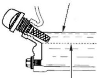
Oil dipstick 2. Oil fill hole 3. Upper limit 4. Lower limit
-
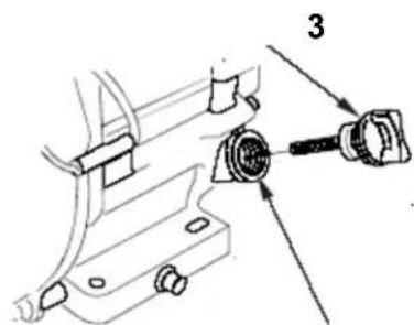
Remove the oil fill cap and slowly pour approximately 80% of the specified amount of oil into the engine.
- Slowly add additional oil to bring the level to the upper limit mark on the dipstick.
- Replace the oil fill cap.
Cleaning the Sediment Cup
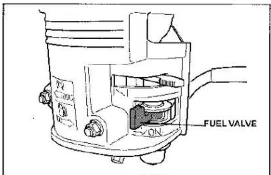
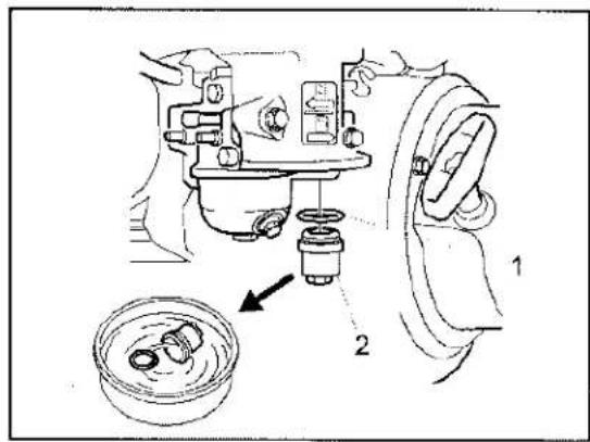
Underneath the fuel valve is a sediment cup to catch dirt in the fuel.
- Move the fuel valve to the OFF position, all the way to the left.
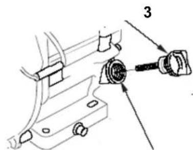
- Unscrew the sediment cup (2). Make sure not to misplace the o-ring (1).
- Clean the reservoir and the o-ring using a cleaning solvent and dry carefully.
- Put the o-ring in place in its groove and replace the sediment cup (2).
Note: Make sure not to misplace the o-ring (1).
- Turn the fuel valve to the ON position, all the way to the right, and check for leaks. If it leaks, replace the o-ring.
Servicing the Spark Plug
Ensure that the air gap between the center and side electrodes is correct before installing the spark plug. Use a spark plug wrench for removing and installing the spark plugs and a gapping tool/feeler gauge to check and adjust the air gap. Install a new spark plug if necessary.
Type: BPR6ES (NKG) or equivalent. Air Gap: 0.28-0.031 inch (0.70-0.80 mm)
Removing the Spark Plugs
- Pull the wire off of the spark plug
- Clean around the spark plug.
- Remove spark plugs and metal washer
Checking the Spark Plugs
- Look at the center of the spark plug. If you see light brown or gray on the insulator, the engine is operating properly. A black coating on the insulator usually means the air cleaner is dirty.
Important: Never clean the spark plug. Always replace the spark plug when it has a black coating, worn electrodes, an oily film, or cracks.
- Check the gap between the center and side electrodes.
- Bend the side electrode if the gap is not correct.
Installing the Spark Plugs
- Thread the spark plugs into the spark plug hole.
- Tighten the spark plugs to 20 ft-lb (27 N-m).
- Push the wire onto the spark plug

natural_image
Line drawing of a hand operating a mechanical component with no visible text or symbols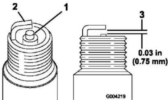
1 Center electrode insulator
2. Side electrode
3. Air gap (not to scale)
Cutting Blades
Among the most critical elements of the Stump Grinder is the cutting blades. It is also the most subject to damage and wear. In the course of grinding stumps it not only makes contact with the wood, but also encounters numerous abrasives and objects in the stump's environment, such as dirt, stones, and occasionally a large rock or buried scrap.
The wear and loss of cutting teeth can significantly impair the efficiency and performance of the stump grinder. Therefore, it is important to make frequent checks of the condition of all of the cutting teeth and replace any damaged or worn blade sections.
Replacing Cutting Blades
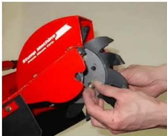
- Clean all dirt from the cutting blade and mounting flanges.
- Remove the two bolts that hold each cutting blade section. Use care not to let a section drop and chip when they become loose.
- Check each section for cracks. Replace blade section if it is cracked or has missing or worn teeth.
-
When replacing cutting blade sections, make sure blade section is placed in correct alignment with blade rotation.
-
Insert blade section between the blade mounting flanges.
-
Slide bolt through one side of flange, and through flange on other side. Install lock washer and nut on each bolt.
-
Tighten securely. Torque to 27-33 ft-lb (37-45 N-m).
natural_image
Close-up of hands operating a red portable saw cutting machine (no visible text or symbols)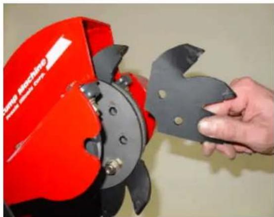
natural_image
Hand holding a red manual cutting tool with a black blade, no visible text or symbolsParking Brake Adjustment
-
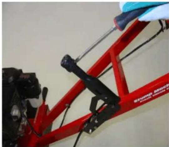
Loosen the setscrew on side of brake lever knob. Turn knob clockwise to tighten brake; adjust counter clockwise to loosen brake. Left wheel should lock completely when brake is set.
-
Tighten the setscrew.
Important: The machine may be tipped backward or on its side to facilitate access for cleaning or service, but no longer than 2 minutes. If the machine is held in this position for too long, the engine can be damaged by gasoline draining into the crankcase. Should this happen, perform an extra oil change on the engine. Then turn the engine over a few revolutions with the starter handle before starting the engine again.
natural_image
Close-up of a red mechanical frame with black clamps and a blue tool, no visible text or symbolsCleaning and Washing
Regular cleaning and washing will increase the machine's life span. Clean the machine directly after use, before the dirt hardens.
Check before cleaning that the fuel tank cap is properly in place to avoid getting water in the tank.
Use care when using high-pressure sprayer because warning decals, instruction signs and the engine can be damaged.
Important: Lubricate the cutting blade bearings after cleaning. This is particularly important if the machine is to be stored.
Lubricating the Bearings
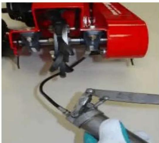
Cutting blade bearings should be greased after every 10 hours of operation.
Grease Type: General-purpose grease.
- Clean the grease fittings with a rag.
- Connect a grease gun to each fitting.
- Lubricate two fittings one on each cutting blade bearing.
- Pump grease into the fittings until grease begins to ooze out of the bearings (approximately 3 pumps).
- Wipe up any excess grease.
natural_image
Close-up of a red industrial machine with metal blades and a tool, no visible text or symbolsImportant: Pump grease in slowly and carefully to prevent damage to the bearing seals.
Drive Belt
The drive belt of the stump grinder is a double-banded 3V-belt.
Note: The belt tension should be checked daily. Replace the belt if it shows any signs of wear, cracks, or damage.
-
Shut off the engine and wait for all rotating parts to stop.
-
Remove belt guard retaining screws.
-
To check belt tension, gently squeeze together. You should be able to depress the belt down about 1/4 - 3/8" (6-10mm) from the original position.
Note: To extend belt life, proper tension must be maintained. A loose belt will cause excessive cutting blade slippage and early belt failure. A belt that is too tight can cause bearing and shaft failure, and rapid belt wear.
Drive Belt Adjustment
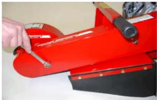
- Loosen the 2 bolts behind the centrifugal clutch.
- Loosen the 4 engine mounting bolts.
- Turn square head adjusting bolt on the frame clockwise to tighten the belt, counter clockwise to loosen the belt.
Important: Make sure to tighten all 6 bolts after proper belt adjustment is achieved.
- Install the belt guard and secure with previously removed hardware.
natural_image
Close-up of a red industrial machine with a hand using a tool to clean or inspect the component (no visible text or symbols)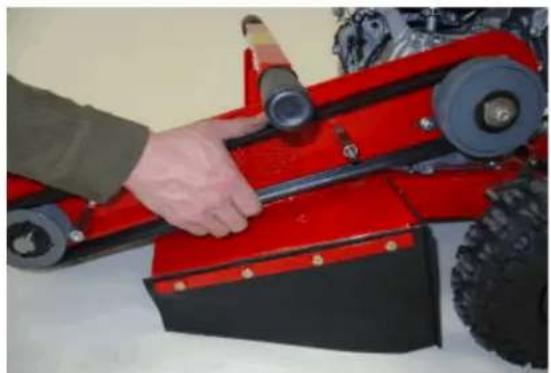
natural_image
Close-up of a red and black toy vehicle with a hand adjusting its wheel (no visible text or symbols)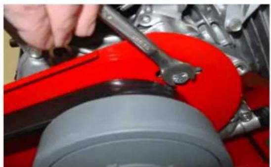
natural_image
Close-up of a red and gray mechanical component being adjusted by hand using a wrench (no visible text or symbols)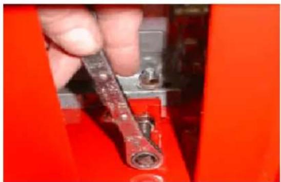
natural_image
Close-up of a hand holding a red mechanical component, no visible text or symbolsStorage
For storage over 30 days, prepare the unit as follows:
- Remove dirt and grime from the external parts of the entire unit, especially the engine. Clean dirt and sawdust chips from the outside of the engine cylinder head fins and blower housing.
Important: You can wash the unit with mild detergent and water. Do not pressure wash the unit. Avoid excessive use of water, especially near the control panel and engine.
- Add a petroleum based stabilizer/conditioner to fuel in the tank. Follow mixing instructions from stabilizer manufacturer. (1 oz. per US gallon). Do not use an alcohol based stabilizer (ethanol or methanol).
Note: Fuel stabilizer/conditioner is most effective when mixed with fresh gasoline and used at all times.
Important: Do not store stabilizer/conditioned gasoline over 90 days.
- Run the engine to distribute conditioned fuel through the fuel system (5 minutes).
- Stop the engine, allow it to cool and drain the fuel tank using a pump type siphon. Dispose of fuel properly. Recycle as per local codes.
- Restart the engine and run it until it stops.
- Choke the engine.
- Start and run the engine until it will not start again.
- Clean the sediment cup; refer to Cleaning the Sediment Cup.
- Service the air cleaner; refer to Cleaning the Cyclone Air Filter and Replacing the Air Filter.
- Change the engine crankcase oil; refer to Changing the Engine Oil.
- Remove the spark plug and check the condition; refer to Servicing the Spark Plug.
- With the spark plug removed from the engine, pour two tablespoons of engine oil into the spark plug hole.
- Pull the starter slowly to crank the engine and distribute the oil inside the cylinder.
- Install the spark plug, but do not install the wire on the spark plug.
- Grease the cutter blade bearings; refer to Lubricating Bearings.
- Check and tighten all bolts, nuts, and screws. Repair or replace any part that is damaged.
- Paint all scratched or bare metal surfaces. Paint is available from your Authorized Service Dealer.
- Store the unit in a clean, dry garage or storage area.
- Cover the unit to protect it and keep it clean.
Troubleshooting
| Symptom | Cause | Action |
| The engine will not start. | Engine switch in OFF position.Fuel valve closed.Choke valve open. | Hold safety bail against handle.Open the fuel valve.Close the choke when starting a cold engine.Fill tank with fresh fuel. |
| Fuel tank empty. | ||
| Spark plug fouled. | Check electrode gap and clean or replace spark plug. | |
| Engine runs rough. | Choke is left on.Clogged air filter.Clogged fuel line.Water or contaminants in fuel. | Open the choke valve.Clean or replace the air filter.Clean sediment cup.Drain and fill the tank with fresh fuel.Check electrode gap and clean or replace spark plug. |
| Worn spark plug or buildup on electrodes. | ||
| Belt slips or comes off pulleys. | Belt tension is insufficient. | Adjust belt tension.Reduce cutting depth. |
| The cutting wheel does not rotate. | Engine speed is insufficient to activate the centrifugal clutch.Belt tension is insufficient.Clutch shoes are worn. | Move throttle to the ENGAGED position.Adjust belt tension.Replace the clutch. |
| The cutting wheel continues to rotate. | Engine speed is excessive.Belt is off pulleys or broken.Clutch springs are weak or broken. | Move throttle to the DISENGAGED position.Replace drive belt.Replace the clutch. |
| The parking brake does not hold. | Parking brake out of adjustment.Brake pads worn. | Adjust the parking brake.Replace brake pads. |
ConditionsandProductsCovered
The Toro®Companyanditsaffiliate, ToroWarrantyCompany, pursuant toanagreementbetween them, jointlywarrantyyourToroCompactUtility Equipment("Product")tobefreefromdefectsinmaterialsorworkmanship. The following time periods apply from the date of purchase:
ProductsWarrantyPeriod
Loaders, Trenchers, StumpGrinders, 1yearor1000operating Chippers, LogSplits, and Attachments hours, whichever occurs first Kohler Engines 3 years All other Engines 2 years
Whereawarrantableconditionexists,wewillrepairtheProductatnocost toyouincludingdiagnosis,labor,andparts.
InstructionsforObtainingWarrantyService
If youthink that your Toro Product contains a defect in materials or workmanship, follow this procedure:
- ContactanyAuthorizedToroCompactUtilityEquipment(CUE) ServiceDealertoarrangeserviceattheirdealership.Tolocatea dealerconvenienttoyou,accessourwebsiteatwww.Toro.com.YoumayalsocallourToroCustomerCareDepartmenttollfree at888-865-5676(U.S.customers)or888-865-5691(Canadian customers).
- Bring the product and your proof of purchase (sales receipt) to the Service Dealer.
- IfforanyreasonyouaredissatisfiedwiththeServiceDealer's analysisorwiththeassistanceprovided,contactusat:
LCBCustomerCareDepartment
ToroWarrantyCompany
8111LyndaleAvenueSouth
Bloomington, MN55420-1196
TollFree:888-865-5676(U.S.customers)
TollFree:888-865-5691(Canadacustomers)
OwnerResponsibilities
YoumustmaintainyourToroProductbyfollowingthemaintenance proceduresdescribedintheOperator'sManual.Suchroutine maintenance,whetherperformedbyadealerorbyyou,isatyouexpense. Partsscheduledforreplacementasrequiredmaintenance("Maintenance Parts"),arewarrantedfortheperiodoftimeuptothescheduled replacementtimeforthatpart.Failuretoperformrequiredmaintenance andadjustmentscanbegroundsfordisallowingawarrantyclaim.
ItemsandConditionsNotCovered
Notallproductfailuresormalfunctionsthatoccurduringthewarranty periodaredefectsinmaterialsorworkmanship. Thisexpresswarranty doesnotcoverthefollowing:
•Productfailureswhichresultfromtheuseofnon-Tororeplacement parts,orfrominstallationanduseofadd-on,modified,orunapproved accessories
•Productfailureswhichresultfromfailuretoperformrequired maintenanceand/oradjustments
•ProductfailureswhichresultfromoperatingtheProductinan abusive,negligentorrecklessmanner
- Partssubjecttconsumptionthroughuseunlessfoundtobe defective. Examplesofpartswhichareconsumed,orusedup,during normalProductoperationinclude,butarenotlimitedto,teeth,tines, blades,sparkplugs,tires,tracks,filters,chains,etc.
- Failurescausedbyoutsideinfluence.Itemsconsideredtobeoutside influenceinclude,butarenotlimitedto,weather,storagepractices, contamination,useofunapprovedcoolants,lubricants,additives,or chemicals,etc.
•Normal“wearandtear”items.Normal“wearandtear”includes,butis notlimitedto,wornpaintedsurfaces,scratcheddecalsorwindows, etc.
• Anycomponentcoveredbyaseparatemanufacturer'swarranty
•Pickupanddeliverycharges
GeneralConditions
RepairbyanAuthorizedToroCompactUtilityEquipment(CUE)Service Dealerisyoursoleremedyunderthiswarranty.
NeitherTheToro®CompanynorToroWarrantyCompanyisliable forindirect,incidentalorconsequentialdamagesinconnectionwith theuseoftheToroProductscoveredbythiswarranty,including anycostorexpenseofprovidingsubstituteequipmentorservice duringreasonableperiodsofmalfunctionornon-usepending completionofrepairsunderthiswarranty.Allimpliedwarranties ofmerchantabilityandfitnessforusearelimitedtotheduration ofthisexpresswarranty.Somestatesdonotallowexclusionsof incidentalorconsequentialdamages,orlimitationsonhowlong animpliedwarrantylasts,sotheaboveexclusionsandlimitations maynotapplytoyou.
This warranty gives you specific legal rights, and you may also have other rights which vary from statetostate.
ExceptfortheenginewarrantycoverageandtheEmissionswarranty referencedbelow,ifapplicable,thereisnootherexpresswarranty.The EmissionsControlSystemonyourProductmaybecoveredByaseparate warrantymeetingrequirementsestablishedbytheU.S.Environmental ProtectionAgency(EPA)ortheCaliforniaAirResourcesBoard(CARB). ThehourlimitationssetforthabovedonotapplytotheEmissions ControlSystemWarranty.RefertotheCaliforniaEmissionControl WarrantyStatementsuppliedwithyourProductorcontainedintheengine manufacturer'sdocumentationfordetails.
CountriesOtherthantheUnitedStatesorCanada
Customers who have purchased Toro product exported from the United States. Canad should contact their Toro Distributor (Dealer) obtain guarantee policies for your country province state for any reason you are dissatisfied with you Distributor's service have difficulty obtaining guarantee information, contact the Toro importer. If all other remedies fail, you may contact us at Toro Warranty Company.
Manual del Operador
natural_image
Technical line drawing of a mechanical vehicle with visible components and mounting brackets (no text or symbols)Figura 1
You require the following personal protective equipment:
- Protective helmet (hard hat)
- Ear protection
- Face guard
- Protective trousers
- Protective glasses
- Breathing protection (risk of dusty work environment)
- Protective gloves
- First aid kit
- Protective boots or steel-toed shoes.
Operación
119-4701
natural_image
Red agricultural machine with yellow warning signs on its side, mounted on a dirt path (no visible text or symbols)natural_image
Close-up of a red bicycle frame with black mechanical clamps and bolts (no visible text or symbols)Contador de horas
natural_image
Line drawing of a person digging with a shovel, surrounded by grass and a small pot (no text or symbols)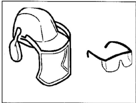
natural_image
Simple line drawing of a helmet and safety goggles (no text or symbols)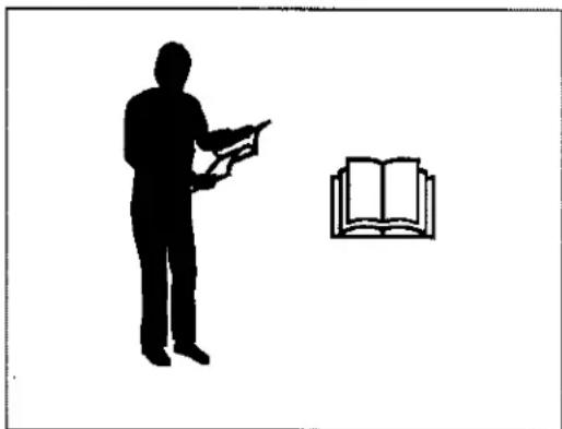
natural_image
Silhouette of a person holding an open book next to an open book (no text or symbols present)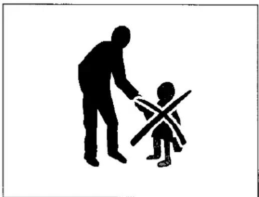
natural_image
Silhouette of an adult and a child interacting, with no text or symbols presentnatural_image
Person pouring yellow liquid into a red fire extinguisher using a small machine (no visible text or symbols)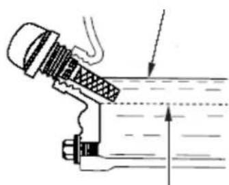
natural_image
Technical line drawing of a mechanical component with an arrow indicating direction (no text or symbols)2
4
natural_image
Line drawing of a hand gripping a cylindrical object (no text or symbols)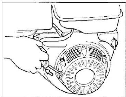
natural_image
Line drawing of hands operating a mechanical component with a circular dial (no text or symbols)Cómo parar el motor
natural_image
Red manual lawn mower on grass with a person operating it, no visible text or symbolsnatural_image
Close-up of a red industrial frame with black components and metallic chains (no visible text or symbols)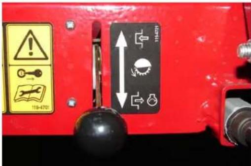
natural_image
Red lawn mower on grass next to a circular tree stump (no text or symbols visible)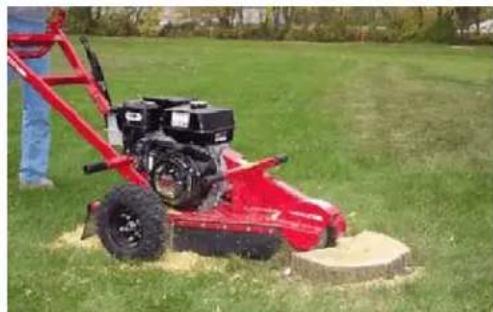
natural_image
Red lawn mower on a grassy field with a person standing nearby (no visible text or symbols)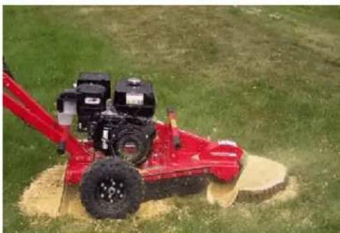
natural_image
Red manual lawn mower on a grassy field, no visible text or symbols
natural_image
Red and black lawn mower on grass, no visible text or symbolsnatural_image
Simple line drawing of a container with a lid and spout, no text or symbols present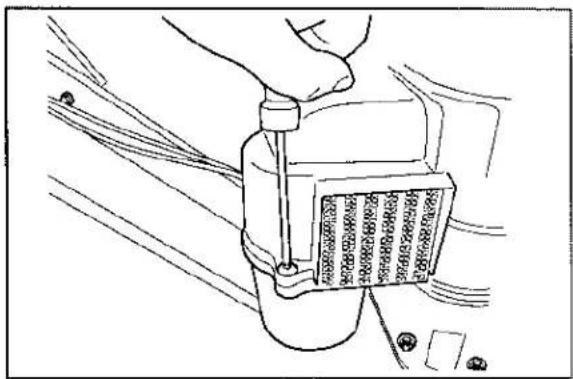
natural_image
Line drawing of a hand using a screwdriver to adjust a component on a vehicle (no text or symbols present)natural_image
Line drawing of a mechanical assembly with hands operating a component (no text or symbols visible)natural_image
Technical line drawing of a mechanical assembly with no visible text or symbolsnatural_image
Hand holding a small container with patterned contents, no visible text or symbolsnatural_image
Close-up of a mechanical assembly with metallic components and red base, no visible text or symbols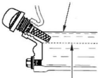
natural_image
Diagram of a mechanical device with a threaded component and fluid flow direction arrow (no text or labels)2
4
natural_image
Line drawing of a hand operating a mechanical device with a tool (no text or symbols visible)natural_image
Close-up of hands operating a red industrial machine cutterhead with a black blade (no visible text or symbols)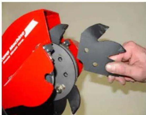
natural_image
Hand holding a red and black saw blade assembly, no visible text or symbols on the device itselfnatural_image
Close-up of a red mechanical frame with black components and a hand adjusting a tool (no visible text or symbols)Limpieza y lavado
natural_image
Close-up of a red and silver tool holder with metal blades, being handled by gloved hands (no visible text or symbols)natural_image
Close-up of a red mechanical device with a hand using a tool to clean or inspect it (no visible text or symbols)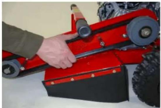
natural_image
Close-up of a red and black robotic vehicle with a hand adjusting its wheel (no visible text or symbols)natural_image
Close-up of a red and gray mechanical component being adjusted by a wrench (no visible text or symbols)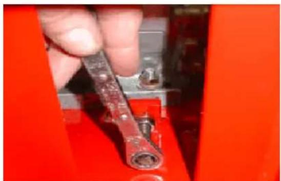
natural_image
Close-up of a hand holding a red wrench against a red background (no visible text or symbols)Almacenamiento
LCBCustomerCareDepartment
ToroWarrantyCompany
8111LyndaleAvenueSouth
Bloomington, MN55420-1196
natural_image
Technical line drawing of a mechanical pump or scrubber assembly (no text or symbols)Figure 1
You require the following personal protective equipment:
- Protective helmet (hard hat)
- Ear protection
- Face guard
- Protective trousers
- Protective glasses
- Breathing protection (risk of dusty work environment)
- Protective gloves
- First aid kit
- Protective boots or steel-toed shoes.
Utilisation
119-4701
natural_image
Red agricultural machine with yellow warning labels, mounted on a dirt field (no visible text or symbols)natural_image
Close-up of a red bicycle frame with black and white components, no visible text or symbolsCompteur horaire
natural_image
Line drawing of a person digging with a shovel, standing on a mound (no text or symbols)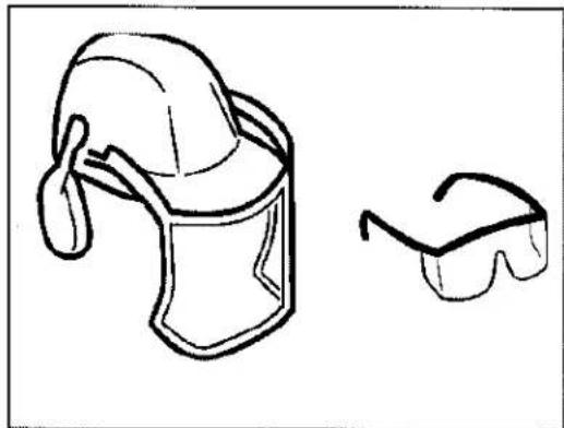
natural_image
Simple line drawing of a helmet and sunglasses (no text or symbols)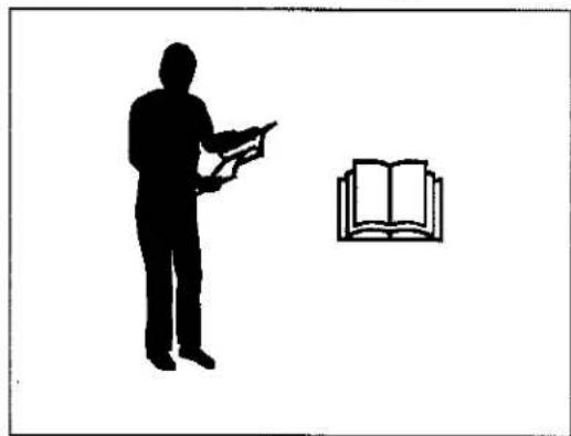
natural_image
Silhouette of a person holding an open book next to an open book (no text or symbols present)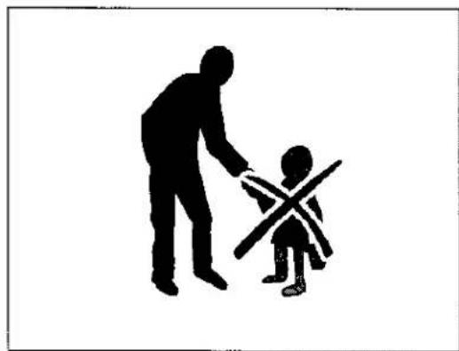
natural_image
Silhouette of an adult and a child interacting, with no text or symbols presentRavitaillement
natural_image
Person pouring yellow liquid into a red bucket pump on a red agricultural machine (no visible text or symbols)natural_image
Diagram of a mechanical device with a lever and fluid flow direction arrow (no text or symbols)2
natural_image
Line drawing of a hand gripping a small object, possibly a tool or device (no text or symbols present)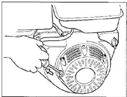
natural_image
Line drawing of a hand adjusting a circular mechanical component with a tool (no text or symbols)Arrêt du moteur
natural_image
Red manual tiller on a grassy field with a person operating it, no visible text or symbols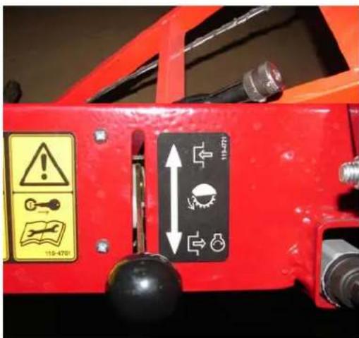
natural_image
Red lawn mower on grass with a circular tree stump in the foreground (no visible text or symbols)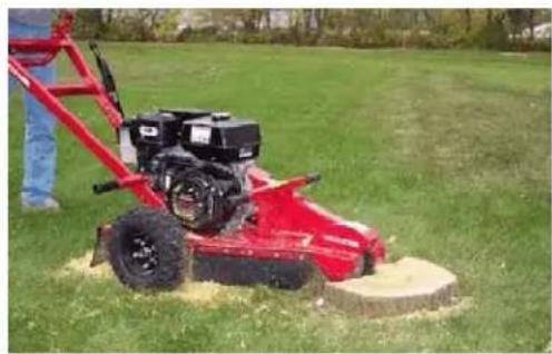
natural_image
Red lawn mower on a grassy field with a person standing nearby (no visible text or symbols)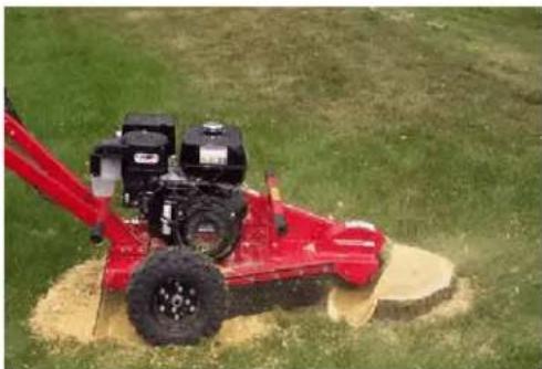
natural_image
Red portable tiller machine operating on a grassy field, no visible text or symbols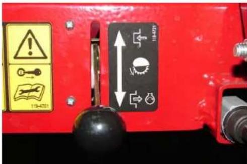
natural_image
Red agricultural machine with attached red frame on grassy field (no visible text or symbols)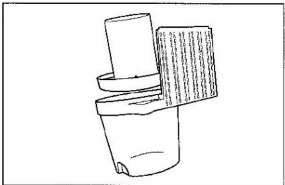
natural_image
Simple line drawing of a container with a lid and a paper sheet, no text or symbols present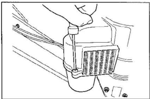
natural_image
Line drawing of a hand adjusting a mechanical component with wires (no text or symbols)natural_image
Technical line drawing of a mechanical assembly with no visible text or symbolsnatural_image
Technical line drawing of a mechanical device with no visible text or symbols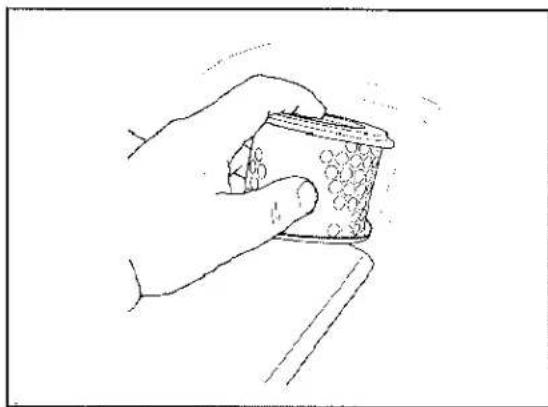
natural_image
Hand holding a small container with decorative patterns (no text or symbols visible)natural_image
Close-up of a red automotive battery pack with metallic components and bolts (no visible text or symbols)natural_image
Diagram of a mechanical device with a spring-loaded component and fluid flow direction arrow (no text or labels)2
4
Entretien de la bougie
natural_image
Line drawing of a hand operating a mechanical device with no visible text or symbolsnatural_image
Close-up of hands operating a red portable saw cutting machine (no visible text or symbols)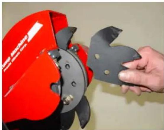
natural_image
Hand holding a red manual cutting tool with a black blade, no visible text or symbolsnatural_image
Close-up of a red bicycle frame with black mechanical components and a hand adjusting the lever (no visible text or symbols)Nettoyage et lavage
natural_image
Close-up of a red industrial machine with a tool and clamped components, no visible text or symbolsnatural_image
Close-up of a red industrial machine with a hand using a tool to clean or inspect the surface (no visible text or symbols)natural_image
Close-up of a red and black mechanical device with a hand adjusting its part (no visible text or symbols)natural_image
Close-up of a red and gray mechanical component being adjusted by a wrench (no visible text or symbols)natural_image
Close-up of a hand using a wrench to adjust a red mechanical component (no visible text or symbols)Remisage
LCBCustomerCareDepartment
ToroWarrantyCompany
8111LyndaleAvenueSouth
- Introduction
- Warning
- CALIFORNIA
- [Non-Text]
- Contents
- Introduction......1
- Safety....4
- Safety and Instructional Decals ......8
- Controls....9
- Specifications....10
- Operating......11
- Adding Fuel ......12
- Checking the Engine Oil Level .....14
- Starting and Stopping the Engine .....15
- Grinding the Stump ......16
- Maintenance ....19
- Storage 29
- Troubleshooting ....30
- Warranty ...... Back Cover
- Safety
- Safe Operating Practices
- Training
- Preparation
- You require the following personal protective equipment:
- Operation
- Slope Operation
- Maintenance and Storage
- Safety and Instructional Decals
- Controls
- Throttle:
- Safety Bail:
- Parking Brake:
- Hour Meter:
- Before you start:
- Adding Fuel
- DANGER
- Using Stabilizer/Conditioner
- Important: Do not use fuel additives containing methanol or ethanol.
- Filling the Fuel Tank
- Checking the Engine Oil Level
- Starting and Stopping the Engine
- Starting the Engine
- Stopping the Engine
- Grinding a Stump
- A rotating cutting blade is very DANGEROUS!
- Maintenance
- Recommended Maintenance Schedule
- Cleaning the Cyclone Air Filter
- Replacing the Air Filter
- Changing the Engine Oil
- Changing the Oil
- Cleaning the Sediment Cup
- Servicing the Spark Plug
- Removing the Spark Plugs
- Checking the Spark Plugs
- Installing the Spark Plugs
- Cutting Blades
- Replacing Cutting Blades
- Parking Brake Adjustment
- Cleaning and Washing
- Lubricating the Bearings
- Drive Belt
- Drive Belt Adjustment
- Storage
- ConditionsandProductsCovered
- ProductsWarrantyPeriod
- InstructionsforObtainingWarrantyService
- OwnerResponsibilities
- ItemsandConditionsNotCovered
- GeneralConditions
- CountriesOtherthantheUnitedStatesorCanada
- Manual del Operador
- Operación
- Contador de horas
- Cómo parar el motor
- Limpieza y lavado
- Almacenamiento
- Utilisation
- Compteur horaire
- Ravitaillement
- Arrêt du moteur
- Entretien de la bougie
- Nettoyage et lavage
- Remisage
Brand : TORO
Model : 22602
Category : Stump grinder