
HALion Sonic 1 - Audio and/or video software STEINBERG - Free user manual and instructions
Find the device manual for free HALion Sonic 1 STEINBERG in PDF.


| Product type | Audio software (VST virtual instrument) |
| Brand | Steinberg |
| Model | HALion Sonic 1 |
| Version | 1.0 (released June 4, 2010) |
| Plugin formats | VST2, VST3, AU |
| Operating systems | Windows Vista, Windows 7 (32/64-bit), Mac OS X 10.5 and 10.6 |
| Minimum processor | Pentium/Athlon dual core 2.0 GHz (Windows), Intel Core Duo 2.0 GHz (Mac) |
| Minimum RAM | 2 GB |
| Required disk space | Approximately 12 GB |
| Recommended screen resolution | 1280 x 800 pixels |
| Protection | USB-eLicenser key (sold separately) |
| Library content | Over 12 GB of sounds, 1000+ ready-to-play sounds, 1500+ FlexPhraser patterns |
| Maximum polyphony | 128 voices per program (adjustable) |
| Number of programs | Up to 16 per instance (multitimbral) |
| Layers per program | Up to 4 (synth, sample, instrument, percussion, loop) |
| Effects | 4 inserts per layer, 4 global AUX busses (up to 4 effects each) |
| Main features | Synthesis, sampling, loop player, FlexPhraser arpeggiator, modulation matrix, built-in effects |
| Standalone mode | Yes, with metronome and MIDI cheat sheet |
| Manual languages | French, German, English |
Frequently Asked Questions - HALion Sonic 1 STEINBERG
User questions about HALion Sonic 1 STEINBERG
0 question about this device. Answer the ones you know or ask your own.
Ask a new question about this device
Download the instructions for your Audio and/or video software in PDF format for free! Find your manual HALion Sonic 1 - STEINBERG and take your electronic device back in hand. On this page are published all the documents necessary for the use of your device. HALion Sonic 1 by STEINBERG.
USER MANUAL HALion Sonic 1 STEINBERG


HALION SONIC
Premier VST Workstation
Heiko Bischoff, Masahiro Eto, Pierre Schaller
Thanks to: Matthias Klag, Michael Ruf
The information in this document is subject to change without notice and does not represent a commitment on the part of Steinberg Media Technologies GmbH. The software described by this document is subject to a License Agreement and may not be copied to other media except as specifically allowed in the License Agreement. No part of this publication may be copied, reproduced or otherwise transmitted or recorded, for any purpose, without prior written permission by Steinberg Media Technologies GmbH.
Steinberg, HALion Sonic, VST and ASIO are registered trademarks of Steinberg Media Technologies GmbH. Windows, Windows Vista and DirectX are registered trademarks of Microsoft Corporation in the United States and other countries. Macintosh, Mac and Mac OS are trademarks of Apple Inc., registered in the U.S. and other countries. Pentium and Intel Core are trademarks or registered trademarks of Intel Corporation in the U.S. and other countries. All other product and company names are TM and ® of their respective holders.
Release Date: June 4, 2010
© Steinberg Media Technologies GmbH, 2010.
All rights reserved.
Table of contents
5 Welcome
5 Key command conventions
6 How you can reach us
6 Installation
8 Getting ready to play
10 About multis, programs and layers
12 HALion Sonic interface
15 Plug-in functions section
17 Multi Program Rack
20 Mix page
20 MIDI page
21 Editing programs
23 Editing layers
24 Voice page
27 Pitch page
28 Oscillator page
30 Filter page
32 Amplifier page
34 Envelope pages
39 LFO pages
42 Step Modulator page
44 Mod Matrix page
46 Modulation Sources
47 Modulation Destinations
48 Modulation Modifiers
49 Inserts page
50 Instrument layer
53 Expression Maps
54 FlexPhraser
59 FlexPhraser Phrases
59 Drum and loop layers
67 Quick controls
71 Trigger pads
73 Global Effects
74 Effects reference
87 MediaBay
90 Options page
91 Multi Chain
95 MIDI controllers
98 Index
Welcome
Congratulations and thank you for purchasing HALion Sonic by Steinberg.
HALion Sonic breaks new ground in terms of performance, versatility and ease of use: you can now work more productively than ever before. HALion Sonic offers over 12 GB of first class synths, hybrid and acoustic instruments, covering almost any conceivable style. With the purchase of HALion Sonic you have chosen the ultimate VST workstation, which is actually a joint venture project on its own: thousands of lines of computer code has been generated in the Steinberg Headquarter in Hamburg, Germany to build an instrument capable of playing back over a thousand ready to play sounds. Created by the Yamaha sound design team behind Yamaha's legendary MOTIF synthesizers, this world-class library with up to 20 articulations per instrument covers an enormous range of styles, all the way from finest detailed acoustic instruments to legendary synthesizers, club sounds and soundscapes, from ultra-realistic acoustic drum kits to the latest hip-hop loops. All included sounds with articulations feature real-time control and support for Steinberg's VST Expression, delivering easy articulation editing in Cubase 5. The massive library also includes over 1,500 patterns for the FlexPhrase module that drives beats, arpeggios and complex tonal phrases, plus automatic articulation switching. HALion Sonic is your go-to composition and production instrument, offering the complete range of sound-shaping and creative editing features you expect from studio-grade instruments. Yet HALion Sonic also shines when performing live: building keyboard or layer splits is absolutely effortless.
Whether you are a musician, producer or both - HALion Sonic is certainly your first choice when it comes to breathtaking authenticity, extraordinary dynamic response and tonal depth available exclusively in this premier workstation virtual instrument, conceived and designed by Steinberg in collaboration with Yamaha. The standalone version allows you to use HALion Sonic without a host application – a great choice for performing live. It has two additional features: the quick-idea scratch pad, which lets you instantly store spontaneous ideas, and the metronome.
Please don't forget to register on MySteinberg in order to gain access to online support offers and additional exclusive services. And check out the HALion Sonic community at our online forum, for tips and other useful information.
We wish you a lot of musical inspiration working with your brand new workstation!
Key command conventions
Many of the default key commands in HALion Sonic use modifier keys, some of which are different depending on the operating system. For example, the default key command for Undo is [Ctrl]-[Z] under Windows and [Command]-[Z] under Mac OS X.
When key commands with modifier keys are described in this manual, they are shown with the Windows modifier key first, in the following way:
[Win modifier key]/[Mac modifier key]-[key]
For example, [Ctrl]/[Command]-[Z] means "press [Ctrl] under Windows or [Command] under Mac OS X, then press [Z]".
Similarly, [Alt]/[Option]-[X] means "press [Alt] under Windows or [Option] under Mac OS X, then press [X]".
Please note that this manual often refers to right-clicking, for example, to open context menus. If you are using a Mac with a single-button mouse, hold down [Ctrl] and click.
How you can reach us
Clicking the Steinberg logo in the top right corner of HALion Sonic opens a pop-up menu where you find items for getting additional information and help:
- On this menu, you can find links to various Steinberg web sites. Selecting one automatically launches your browser application and opens the page.
On the web sites you can find support and compatibility information, answers to frequently asked questions, links for downloading new drivers, etc. This requires that you have a browser application installed on your computer, and a working internet connection.
- When you choose the Help item, an online version of the documentation opens.
- You also find a menu item for the registration of your product.
For further information see "Register your software!" on page 7.
Installation

Please read the following section before installing HALion Sonic.
The USB-eLicenser
Many Steinberg products, including HALion Sonic, use the USB-eLicenser, a hardware copy protection device. HALion Sonic will not run without an eLicenser containing an activated license.

The USB-eLicenser is a separate product, and is not included in the product package of HALion Sonic.
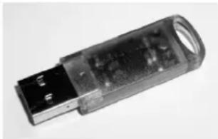
The USB-eLicenser
The USB-eLicenser is a USB device on which your Steinberg software licenses are stored. All hardware-protected Steinberg products use the same type of device, and you can store more than one license on one device. Also, licenses can (within certain limits) be transferred between USB-eLicensers – which is helpful, for example, if you want to sell a piece of software.
The product package of HALion Sonic contains an activation code, which is found on the Essential Product License Information card within the product package. To make unlimited use of your version of HALion Sonic, you must manually download a license to an USB-eLicenser connected to your computer, and activate your permanent license using the activation code.
The eLicenser Control Center (which can be found on the Start menu on Windows systems or in the Applications folder on a Mac after installation of HALion Sonic) is the place where you can check the licenses installed on your USB-eLicenser, and activate new licenses.
To check the installed licenses, click the "Enter Activation Code" button in the eLicenser Control Center and follow the instructions.
- If you are using other copy-protected Steinberg products, you may want to transfer all licenses for your applications to one USB-eLicenser, thus using up only one USB port of your computer.
Please refer to the eLicenser Control Center Help for information on how to transfer licenses between USB-eLicensers.
System requirements
To use HALion Sonic, your computer must meet the following requirements:
Windows
- Windows Vista and Windows 7 (64-bit version natively supports 64-bit versions of Vista and Windows 7)
- Pentium/Athlon 2.0 GHz dual core mobile or dual core 2.0 GHz processor
· 2 G B R A M - Approx. 12 GB of free hard disk space
- Display resolution 1280 x 80 0 pixels recommended
- Windows DirectX compatible audio hardware (ASIO compatible audio hardware recommended for low-latency performance)
- DVD-ROM drive with dual-layer support
- USB component port for USB-eLicenser/Steinberg Key (license management)
- USB-eLicenser/Steinberg Key is required (not included)
- Internet connection for license activation
- For using as plug-in, a VST2 or VST3 compatible host is required
Macintosh
- Mac OS X 10.5 and 10.6
- Intel Core Duo 2.0 GHz processor
· 2 G B R A M - Approx. 12 GB of free hard disk space
- Display resolution 1280 x 80 0 pixels recommended
- CoreAudio compatible audio hardware
- DVD-ROM drive with dual-layer support
- USB component port for USB-eLicenser/Steinberg Key (license management)
- USB-eLicenser/Steinberg Key is required (not included)
- Internet connection for license activation
- For using as plug-in, a VST2, VST3 or AU compatible host is required
Installing HALion Sonic
Since HALion Sonic provides a large amount of content, the porduct package contains two DVDs. Please have all DVDs ready, because you will be asked to remove one DVD and insert the next one during the installation.
The installer of HALion Sonic allows you to save the content files on a different hard drive than the program files.
Proceed as follows:
-
Insert the first DVD into your DVD drive.
An interactive start screen appears. If the interactive start screen is not opened automatically or if you have a Macintosh computer, you can manually open the interactive start screen by double-clicking the file
"HALion_Sonic_Start_Center.exe" under Windows or "HALion Sonic Start Center.app" on a Macintosh computer. -
Follow the instructions on screen to start the installation of HALion Sonic and browse through the additional options and information presented.
If you do not want to install HALion Sonic via the interactive start screen, follow the instructions below:
Windows
- Double-click the file called "Setup.exe".
- Follow the instructions on screen.
Macintosh
- Double-click the file called "HALion Sonic.mpkg".
- Follow the instructions on screen.
Register your software!
We encourage you to register your software! By doing so you are entitled to technical support and kept aware of updates and other news regarding HALion Sonic.
Proceed as follows:
- Click the Steinberg logo in the top right corner of the control panel and select "Register HALion Sonic now!" from the pop-up menu.
This option is an internet link that opens the registration page of the Steinberg web site. To register, simply follow the instructions on screen.
Getting ready to play
The following sections describe how to use HALion Sonic as a plug-in in different host applications, or as a stand-alone instrument.
Setting up HALion Sonic as a VST instrument in Cubase
The following information refers to the use of HALion Sonic in Cubase. We assume that you have correctly set up Cubase as well as your MIDI and audio hardware, and that Cubase receives MIDI data from your external MIDI keyboard. If you want to use HALion Sonic in another VST host application, please refer to the documentation of the corresponding application.
Cubase provides two ways of working with VST instruments: the VST instruments window, or instrument tracks.
To access HALion Sonic via the VST instruments window, proceed as follows:
- Open the Devices menu in Cubase and select the VST instruments option to open the VST instruments window.
- Click on one of the empty slots to open the instrument pop-up menu and select HALion Sonic.
- You will be asked whether you want to create an associated MIDI track connected to the VST instrument. Click Create.
HALion Sonic is loaded and activated, and its control panel opens. A MIDI track called HALion Sonic is added to the Track list. The output of this track is routed to HALion Sonic.
To access HALion Sonic via an instrument track, proceed as follows:
- Open the Project menu, and select "Instrument" from the Add Track submenu.
- The Add Instrument Track dialog is opened. Select HALion Sonic from the instrument pop-up menu.
- Click OK to create the instrument track. Click the Edit Instrument button in the Cubase Inspector to open the control panel of HALion Sonic.
HALion Sonic has now been set up as a VST instrument in Cubase. For more details about the handling of VST instruments, see the Cubase Operation Manual.
Working with individual outs
HALion Sonic loads in a stereo output configuration by default. However, you can use up to 15 additional individual outs in Cubase. This allows you to route all 16 program slots to a dedicated Cubase Mixer channel.
To make these outputs available:
- Open the Instrument window.
- Click the output button for HALion Sonic instrument.
- Activate the outputs you want to use.
Cubase automatically creates a MIDI track for each additional output and adds a channel to its mixer. You can now route HALion Sonic programs, layers or drum instruments (Slices) to these outputs for further signal processing within Cubase.
Using HALion Sonic in an AU compatible application
You can use HALion Sonic in an AU host application (e. g. Logic). The AU version of HALion Sonic is installed in your AU plug-ins folder and lets HALion Sonic work in an AU environment without any performance loss or incompatibilities.
For Logic Pro 8, proceed as follows:
- Open the Track Mixer and select the desired instrument channel.
- [Command]-click the I/O field, and select either Multi-Channel or Stereo from the pop-up menu that opens.
- In the submenu that appears, select All instruments. Then select HALion Sonic. HALion Sonic is now loaded as an AU instrument.
HALion Sonic standalone
HALion Sonic can be used as a standalone application, independently of any host application. In this case, you can connect HALion Sonic directly to your audio hardware.
- To retain your HALion Sonic settings, you must save them as a preset (click the disk symbol to the left below of the HALion Sonic logo).
The Preferences dialog
When running HALion Sonic as a standalone application, you can configure the application in the Preferences dialog. To open the Preferences dialog, proceed as follows:
- Click the Open Preferences button (the cogwheel symbol) to the right of the audio output field.
Click here to open the Preferences dialog.
- Right-click in the topmost section of the control panel and select "Preferences" on the context menu.
The Preferences dialog has several pages in which you can make the following settings:
- On the MIDI Routing page, use the MIDI Input Port pop-up menu to specify a MIDI input. Use the Channel Filter option to decide whether HALion Sonic should record MIDI events on all MIDI channels, or only on one specific channel. Use the "Filter 'All Notes Off' Controller" option to avoid unwanted "All Notes Off" messages.
Such messages are sent by some keyboards when the user releases the last key. This causes HALion Sonic to stop playback, even when the sustain pedal is still in use.
- On the Audio Routing page, use the Audio Output Port pop-up menus to assign different audio outputs.
HALion Sonic supports 32 channels: two Main channels (left and right) and 15 additional stereo channels (left and right). You can assign different audio outputs for each channel. Selecting an audio output on the pop-up menu maps the output to the corresponding channel.
If you press [Shift] and select an audio output, the front and rear channels are set to incrementing audio output ports - e.g. 1, 2, 3, 4 or 5, 6, 7, 8. If you press [Alt]/[Option]-[Shift] and select an audio output, the audio outputs are assigned in pairs to the front and rear channels - e.g. 1, 2, 1, 2 or 5, 6, 5, 6.
- On the Metronome page a number of settings can be made regarding the use of a metronome:
Option Description
| Mode Here you can turn the metronome Count In mode. | on and off or set it to |
Accent Activate this to accentuate the first beat of each bar.
| Level | Use this fader to adjust the volume level of the metronome. |
| Connections | Here you can select a separate stereo output for the metronome. |
- On the General page, activate "Don't prompt for confirmation when quitting HALion Sonic" if you want HALion Sonic to close without prompting when quitting the program.
- On the ASIO Driver page, select your audio hardware driver from the ASIO Driver menu.
If you plan to use several audio applications simultaneously, you may want to activate the option "Release Driver when Application is in Background". This will allow another application to play back via your audio hardware even when HALion Sonic is running.
The input and output latency values for your audio hardware are displayed. "Latency" is the amount of time it takes for your system to respond to any messages that are sent to it. High latency results in a noticeable delay between when you press a key and when you hear the sound. Below the latency values, the sample rate that is set for the connected audio hardware is displayed.
When you run HALion Sonic, there are several processes fighting for access to processor time in your computer. The parameter "Audio Priority" allows you to determine which processes have priority:
- Once you have selected the driver, open the Advanced page to specify which inputs and outputs should be used and name these. Click the Control Panel button to open the control panel for the audio hardware and adjust the settings as recommended by the audio hardware manufacturer.
Missing content
There may be situations in which a content file becomes unavailable. The reason can be a closed encrypted partition or a detached removable hard drive, for example. In these cases, you will be prompted that a specific VST Sound Library cannot be informed.
To access the content again, proceed as follows:
- Click Ignore.
HALion Sonic is loaded, containing the content that could be found. - Quit HALion Sonic.
- Reattach the removable hard drive or reopen the encrypted partition.
- Launch HALion Sonic.
If content files or models are missing for another reason (e.g. if you moved them onto another hard drive after installation, or if you have added a hard drive, thereby "shifting" the partitions), proceed as follows:
- In the window with the message regarding the missing VST Sound Library, click Locate if you want to choose a different file location. A file dialog opens.
- Browse the directory where the content is located.
- Select the file and click Open. All content files that are found in this location become available.
- Click Remove if you do not want HALion Sonic to search for a particular file in the future.
→ You can activate the "Do not ask again" option if you want to ignore or remove all missing files at once.
About multis, programs and layers
Multis
HALion Sonic is a 16 times multi-timbral plug-in, which means that you can load up to 16 sounds so-called programs, to combine them. This combination is called multi. You can use them, for example, to layer several programs or to quickly create split sounds by setting multiple programs to the same MIDI input channel. The most common usage, however, is to create sound sets with different instruments set to individual MIDI channels.
Programs
A HALion Sonic program can be understood as a complex instrument or sound which combines up to four so-called layers. Load a few programs and go to the Edit page to see how those programs are constructed. Often, a program contains a single layer which already comes with all necessary components such as the synthesis part or insert effects. This is because a layer already is a complete sound structure on its own. The program adds the possibility of combining different layers to build up even more complex sounds or to create combinations of sounds you want to load as a unit. A typical example would be a bass / piano split sound or a piano / string layer sound.
Because of the various layer types which come with HALion Sonic, these combinations can do a lot more. For example, think of combining a pulsating synthesizer sequence with a sliced loop completed by a bass on the lower keys and so on. Finally add some effects on individual layers or on the whole program and you will get a unique sound experience. You will find that the options are endless.
Layers
Each of the four layers of a program can use one of the five different layer types that come with HALion Sonic. You can choose between synth, sample, instrument, drums and sliced loop layers. Each layer type is based on an individual sound architecture and provides an adapted editor.
Synth and sample layers
For synth and sample layers, you will get access to a fully-fledged synthesizer editor with components such as a highly flexible filter section, powerful multi-stage envelopes, LFOs, a Step Modulator and a Modulation Matrix. These layer types differ in their basic sound source. While a synth layer provides an oscillator section with three main oscillators, namely a sub oscillator, a noise generator and a ring modulation stage, the sample layer loads a specific multi sample instead.
Drum layers
The drum layers load a multi-sampled drum set, where you can individually adjust the most important parameter per drum instrument. Each drum instrument can be set to a specific pan position or individual output, be filtered, reversed, and so on.
Loop layers
Loop layers load a sliced loop, which is a combination of a loop specific MIDI phrase and the individual slices mapped out onto the keyboard. You can then either play the original loop, transposed version of it or trigger single slices manually. Each slice can be modified with the same parameters as the drum instruments.
Instrument layers
Instrument layers contain several multi samples of an instrument that can either be sound parts or completely different articulations. These sublayers are called Expression. Every Expression can be modified individually by its most important parameters or simply be turned off, to speed up loading time for sound, where not all of the Expressions are needed.
HALion Sonic interface
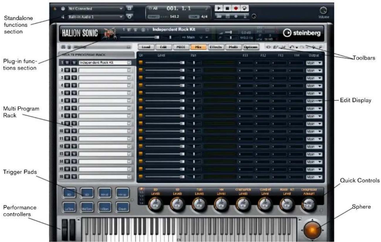
The HALion Sonic interface follows a fixed size, single window concept and is subdivided into several main sections. To save pixel space on the computer monitor it can be collapsed to a smaller version which only shows one slot with the most important sections and hides the Multi Program Rack and Edit Display sections.
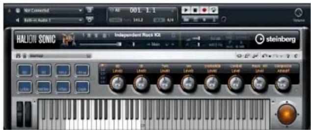
Collapsed View
Plug-in functions section

At the top of the HALion Sonic window you find the plug-in functions section. It contains important controls such as the main volume, tuning, indicators for disk activity and CPU load, as well as the number of voices currently played. Furthermore, it provides a duplicate of the currently focused slot and the program loaded in this slot.
Multi Program Rack
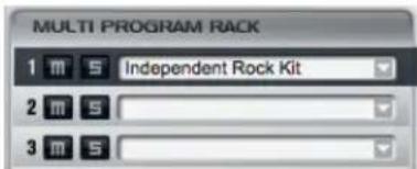
In the Multi Program Rack (located to the left of the Edit Display) you can load up to 16 programs into HALion Sonic. Slots can be muted or soloed. Programs can be selected to edit their parameters.
You can load programs into slots by drag&drop from the Load page. You can also click the down arrow button to open the MediaBay.
Edit Display
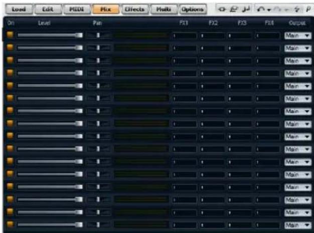
The Edit Display is a multipurpose display that shows various editor views depending on the selected page and slot. There are seven pages that can be chosen using the page switches above the editor views. These pages are the Load, Edit, MIDI, Mix, Effects, Multi and the Options page.
Load page
The Load page gives you access to the huge library that comes with HALion Sonic. It provides an interface to the integrated MediaBay which is used to categorize and rate multis, programs and layers. It allows you to quickly find the sounds you are looking for and of course it conveniently manages all the sounds that you create as well.
Edit page
The Edit page allows you to edit all the parameters that exist inside a program. This comprises the parameter of up to four layers as well as all parameters for the integrated FlexPhrasers and insert effects.
MIDI page
The MIDI page shows the MIDI parameters of all 16 programs and allows you to adjust parameters such as MIDI Channel, Low Key, High Key, Low Vel, High Vel and Polyphony.
Mix page
The Mix page shows the main audio parameters of all 16 programs and allows you to adjust parameters such as level, pan, output, effect send levels for the four AUX effects that can be commonly used. In addition, it also displays a level meter for each slot.
Effects page
The Effects page gives you direct access to the four AUX busses used to realize global send effects as well as the main bus. Each bus can load up to four inserts in serial order to create further sophisticated multi effects.
Multi page
The Multi page allows you to manage and control the so-called Multi Chains. Multi Chains consists of a list of up to 128 multis. This gives you quick access to all multi presets, for example, during a live performance situation.
Options page
The Options page provides you with all the parameters that can be set for the HALion Sonic plug-in.
Toolbars

Above the Edit Display section you find two small toolbars with various useful global functions.
Global insert, AUX and FlexPhraser buttons
Use these buttons to switch off all insert effects, all AUX effects and all FlexPhrasers for the whole plug-in at once. For instance, you can use this feature to quickly compare sounds with and without effects or to use a preset without the FlexPhrasers that have been stored with the preset.
Undo/Redo
HALion Sonic features an undo/redo command stack that allows you to undo or redo the last 10 operations. With the aid of this function you can test new settings without having to worry about losing any of your previous settings.
You can either click the Undo/Redo buttons to undo or redo a single step or:
- Click on the small triangles to see Undo/Redo history.
- Click on an entry in the history list to go back (or forward) to that particular step.
Ö You cannot undo loading a multi (instance) preset.
MIDI Reset
The MIDI Reset button allows you to reset all playing MIDI notes and sounds with one single click.
Editor / Player
This button toggles between the two views available for HALion Sonic: the full-size editor view (e), and the smaller player view (p).
Trigger Pad section
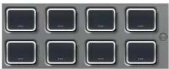
The pads section shows eight pads used for triggering complex chords, remote controlling key switches, etc.
Quick controls

The HALion Sonic quick control section provides you with eight quick controls that can be used to directly adjust the most important parameters of a program. In addition, you can also switch to the four sets of layer quick controls.
Performance controllers
Wheels
The wheels on the left side represent the pitch and modulation wheels on a hardware controller keyboard and can be used in the same way.
Keyboard

The virtual 88-note keyboard of HALion Sonic can be used to trigger MIDI notes just like a real keyboard. By clicking the keys on different vertical positions you can control the note on velocity. Furthermore, the keyboard displays keys that are not used to trigger notes but act as key switches. The up/down switches on the left and right side of the keyboard shift the keyboard range by octaves. This allows you to display, for instance, key switches that are located on lower keys.
Sphere
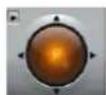
The sphere control is a 2-dimensional-controller that acts as two quick controls, one for vertical and one for horizontal movements. This can be used, for example, to control the morphing filter.
Standalone functions section

Using HALion Sonic as a standalone application adds the standalone functions section above the plug-in. Here you can set Audio and MIDI interface routings, adjust the main volume and get access to the integrated MIDI scratch pad that allows you to easily record your musical inspirations without having to start a MIDI sequencer application. It can also be used to play multi track arrangements that trigger the 16 different sounds inside HALion Sonic.
Plug-in functions section
Introduction
The plug-in functions section gives you access to general functions of the plug-in. It is divided into three sections: program slot, master section and performance displays. With Master Volume and Master Tune you can control the overall loudness and tuning of the plug-in. A large display shows you the name of the currently selected program along with its main parameters. With the performance displays you can monitor the Polyphony and Mono Voices, or the Memory, CPU and Disk usage of the plug-in.
Program slot

The program slot shows the main program parameters for the program currently selected in the Multi Program Rack. You can adjust settings such as level, pan, output bus, MIDI channel and polyphony. Furthermore, you can use the program slot to load programs and to mute/solo them.
Slot selector
The slot number not only serves as a label but also allows you to select the slot you would like to have displayed.
To select the slot:
-
Open the context menu on the number.
-
Select the desired slot.
To make the slot selection easier, programs already loaded will be displayed with their name.
Loading programs into the slot
To load a program directly into the program slot:
- Switch to the Load page and double-click the desired program.
- Drag the program and drop it to the name field of the program slot.
Alternatively you can click the load program button on the right end of the program loader to open a MediaBay dialog. You can then load the program from there. This method is especially useful when you are working with the smaller Player view that does not have direct access to the Load page.
Loading layers into the slot
You can also load a layer preset directly into the program slot. In this case, HALion Sonic creates a new program and drops the layer into the first of its four layer slots. To load a layer into the slot, use the Load page or the Media Bay Browser Window in the same way as for programs.
⇒ Be sure to have the view filter for layers active. Otherwise you will see program presets only.
Aborting the loading of layers
Programs containing lots of sample data may take some time to load. In this case, a progress bar is shown directly in the slot. In addition, the Load button changes to an "Abort" button (x) that allows you to stop the loading process and to reset the slot to the previous state.
Removing programs from a slot
To remove a program from the slot:
- Open the context menu on the program name.
- Select "Remove Program".
Saving a program
To save a modified program:
- Open the context menu on the program name.
- Select "Save Program".
The program will be saved in your user folder.
MIDI activity indicator
The MIDI icon indicates incoming MIDI data by blinking.
Solo
Enable the Solo button of a slot in order to hear only the respective program.
Mute
Enable the Mute button to turn off a program. The program remains loaded and can therefore be turned on again smoothly.
Loading programs into the program slot
To load a program into the slot you have two options:
- Switch to the Load page and double-click the desired program.
- Drag the program and drop it to the desired slot.
Level
Use the level fader to adjust the output level of the slot. The maximum value is +12dB (the default value is ±0dB).
Pan
Use the pan fader to adjust the position of the slot in the stereo panorama.
Output
Use the output selector to define the output destination of the slot signal. By default all signals are sent to the Main output.
Polyphony
This parameter allows you set the number of keys you can play simultaneously. Keep in mind that one key can trigger several layers. Check the Performance Meter to see how many voices are triggered by your playing.
Program Icon
The program icon on the left side shows to which Category of sounds the preset belongs. It cannot be assigned freely but depends on the Category and Sub Category tagged in the MediaBay. If no Category is set, a default icon will be shown.
Master section
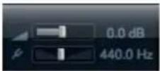
Master Volume
Use the Main Volume knob to adjust the overall volume of HALion Sonic. The maximum value is +12dB (the default value is ±0dB).
- Turn the control clockwise by clicking on it and dragging upwards to raise the volume.
- Turn the control counter-clockwise by clicking on it and dragging downwards to lower the volume.
Master Tune
You can set the Master Tune within a range from 415.3Hz to 466.2Hz, which equals -100 cents to +100 cents. The default value is 440Hz.
Performance displays
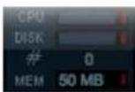
In the upper right of the plug-in panel, you find meters and text displays that indicate the system load of the plug-in.
CPU
This meter shows the processor load during playback of voices. The more voices you play, the higher the processor load will be. If the red overload indicator lights up, reduce the Max Voices setting on the Options page.
Disk
This meter shows the hard disk transfer load from streaming samples or loading presets. If the red overload indicator lights up, the hard disk is not supplying data fast enough to the computer. In such a case, adjust the Disk vs. RAM slider on the Options page towards RAM. You can also decrease the Max Voices setting on the Options page.
Polyphony (Mono Voices)
This display indicates the number of samples currently played back to help you trace performance problems. For example, if you have to reduce the Max Voices setting on the Options page, you can verify your settings by monitoring the Voices display.
Memory
MEM is an abbreviation for Memory. This display indicates the overall amount of RAM currently used by the plug-in and the loaded programs. The amount you see results from the streaming buffer and the preloaded samples. The MEM display helps you to trace performance problems. For example, if you need to free memory for other applications, you can do so by adjusting the Disk vs. RAM slider on the Options page towards Disk. You can verify your settings by monitoring the MEM display.
Reset MIDI

Sometimes notes can get stuck, due to reasons such as the plug-in losing MIDI connection, or the plug-in receiving wrong MIDI controller data. In such a case, you can "emergency reset" the plug-in:
- Click the Reset MIDI button (the lightning icon) located under the Steinberg logo to send an "All Sound Off" and "Reset All Controllers" message to the plug-in.
This is the same as sending the MIDI controllers 120 (All Sound Off) and 121 (Reset All). The plug-in stops play-back immediately and resets the controllers to their default values.
Steinberg logo and about box

If you click on the Steinberg logo in the upper right corner of the plug-in, a pop-up menu opens. You can open the manual in pdf format by selecting Help. Selecting one of the other options opens your default internet browser, directing you to the Steinberg web site. To check for software updates and to find information for trouble shooting, select the corresponding link from the menu.
- To open the manual in pdf format, a pdf reader application must be installed on your computer.
- Your computer needs an active and working internet connection to access the Steinberg web site.
If you click on the plug-in logo in the upper left of the control panel, the about box opens. It contains information regarding the version and build number of the plug-in. With the plug-in version and build number you can verify if your software is up-to-date. Please visit www.steinberg.net regularly to check for updates. To close the about box, click on it or press [Esc] on your computer keyboard.
Multi Program Rack
Introduction
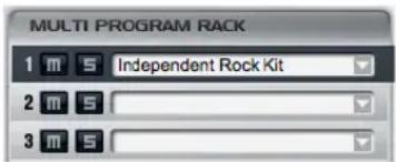
The Multi Program Rack provides 16 slots, so you can load up to 16 programs simultaneously. To show which program is triggered, the slot number indicates incoming MIDI data by blinking. Also, each slot provides a Solo and a Mute button. The Multi Program Rack is linked to the various pages of the Edit Display: When the Edit page is open, you can click individual slots in the Multi Program Rack and see the settings for each loaded program. Additional slot parameters such as level, pan, MIDI channel, etc. can be found on the MIDI and Mix pages.
Managing multis
Above the Multi Program Rack you find the multi preset controls which can be used to load, save and remove multi presets for the entire plug-in.
When using HALion Sonic as a plug-in in Cubase or Nuendo, you will find these presets listed in the Preset Management pop-up menu of the host application.
When using HALion Sonic as a plug-in in a different host application, you can use either this host's preset functionality, or the multi preset features provided by HALion Sonic.
Loading multis
To load a multi preset you have two options:
- Switch to the Load page in the Edit Display and double-click the desired multi preset or drag the multi preset and drop it onto the multi loader.
- Click the Load button to open a MediaBay browser window and load the multi program with a double-click.
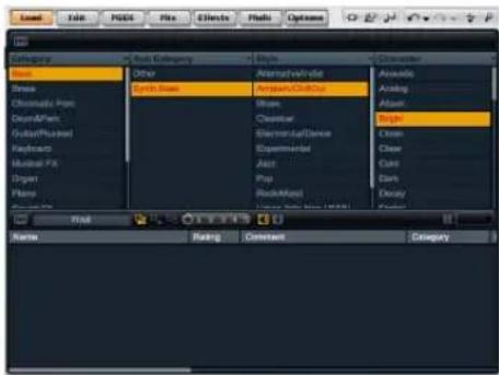
MediaBay
Saving multis
To save multi presets with HALion Sonic's integrated multi preset management:
-
Click the disk icon button in the multi preset slot to open the save dialog.
-
Enter the name of the multi.
-
Assign any tags you require.
-
Click OK.
If you choose an existing file name, you will be asked whether you want to "Overwrite" the file. If not, press "Cancel" to modify the name first or press "Make Unique Name" to add a number suffix (-01,-02,...) to the preset name.
Removing a multi
To remove all loaded programs, and to reset HALion Sonic to its default state, click the trash button.
Loading programs into slots
To load a program into a specific slot you have two options. You can either:
-
Switch to the Load page in the Edit Display and double-click the desired program.
-
Drag the program and drop it to the name field of the program slot.
Or you can click the Load program button on the right to open a MediaBay browser window and load the program from there. This method is especially useful when in the Player view, where the Load page is not available.
When you reopen the MediaBay browser on a slot that already has a program loaded into it, the Category and Sub Category filters will automatically be set to those of the current program. Through this, it becomes very easy to exchange sounds with similar ones at a later stage, without having to readjust the search filter settings again. Of course, you can then modify your search or reset it completely to see all presets.
→ Clicking an empty slot automatically switches the editor to the Load page.
Loading layers into slots
You can also load a layer preset directly into a program slot. In this case, HALion Sonic creates a new program and drops the layer into the first of its four layer slots. To load a layer into a specific slot, use the Load page or the MediaBay browser window in the same way as for programs.
⇒ Be sure to have the view filter for layers active. Otherwise you will see program presets only.
Aborting the loading of programs
Programs containing lots of sample data may take some time to load. In this case, a progress bar is shown directly in the multi and/or program slot. In addition, the Load button changes to an "Abort" button (x) that allows you to stop the loading process and to reset the slot/multi slot to its previous state.
Removing programs from slots
To remove a program from a slot:
-
Open the context menu on the program name.
-
Select "Remove Program".
Saving program
To save a modified program:
- Open the context menu on the program name.
- Select "Save Program".
The program overwrites the original program on your system. Note that you cannot overwrite protected factory content. In this case, the save dialog appears.
Saving program as...
To save a modified or new program under another name:
- Open the context menu on the program name.
- Select "Save Program As...".
- The save dialog appears.
- Enter the new name and set the database attributes.
- Click OK to save the program.
Reverting to last saved program
Use this option to reload the program as it was saved the last time. This allows you to step back to where you started in case you realize that your edits have gone into the wrong direction:
- Open the context menu on the program name.
- Select "Revert to last saved Program".
⇒ You do not need to save a program first to use this option. Without a previous save action the program will simply be reloaded in its original version.
Renaming a program
To edit the name of a program directly in the Multi Program Rack:
- Double-click the program name.
- Enter the new name.
- Press Enter.
When you save the program, the "Save as" dialog suggests a file name.
Switching between slots
You can use the arrow up and down keys of your computer keyboard to select a slot. This allows you to move from one program's settings to another quickly.
MIDI activity indicator
The slot number not only serves as a label but also indicates incoming MIDI data by blinking.
Solo slots
Enable the Solo button of a slot in order to hear only the respective program. You can also enable multiple slot Solo buttons. Note that several slots can be soloed at the same time.
Muting slots
Enable the Mute button to turn off a program. The program remains loaded and can therefore be turned on again smoothly.
Save dialog options
Adding folders within the save dialog
You can create subfolders inside your user preset folder to organize your presets. Normally, this is not necessary to retrieve presets - for this purpose you would rather use the tagging and search function of the MediaBay - but it allows you, for example, to copy presets to their own folder and move them to a different location.
Navigating through the folder hierarchy
You can move through your folder hierarchy using the three navigation buttons in the title bar. These allow you to:
- Go to the previous Browse location.
- Go to the next Browse location.
- Browse the containing folder.
Tagging with the save dialog
When you save a preset, the save dialog opens and shows the tagging editor section on the right side. Here you can easily edit your tags before saving the preset. To make it even simpler, you can first click an existing preset file in the file list on the left to copy its name and all its tags, then make changes the new preset requires, modify the preset name and save it.
Mix page
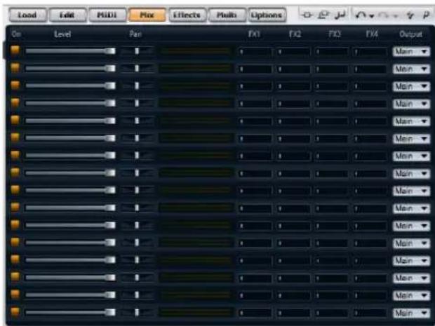
Introduction
The Mix page gives you access to the audio slot parameters of HALion Sonic. This comprises the level and pan settings, as well as the AUX effect sends and the output selector. To control the output levels, each slot also features a level meter.
On/Off
This switch allows you to turn the MIDI input of the slot on and off. In contrast to the Mute function that only mutes the audio output of the slot but keeps on processing the sound in the background, this switch interrupts the MIDI communication with the slot and prevents sounds from being processed.
Level
This parameter allows you to set the output level of the slot.
Pan
This parameter allows you to set the position in the stereo panorama.
Meter
The meter displays the slot output level.
FX1-4 Send Levels
Here you can specify the amount of signal sent to the four auxiliary busses which host up to four effects each.
Output
This parameter defines to which of the 16 plug-in outputs the slot is routed. All slots are routed to the Main output by default.
MIDI page
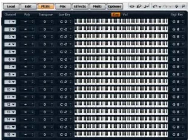
Introduction
The MIDI page gives you access to the MIDI slot parameters of HALion Sonic. This comprises the MIDI channel, Key and Velocity ranges as well as Transpose and Polyphony settings.
Channel
Here you can specify on which MIDI channel a slot should "listen". You can set multiple slots to the same MIDI channel and trigger them simultaneously with the same note events.
Poly (phony)
This setting is used to specify how many notes can be played at the same time. Since programs can contain up to four layers, the resulting number of voices (stereo samples, synth voices etc.) can be much higher than the value specified here.
Transpose
Here you can shift the incoming MIDI notes by +/- 64 semitones before they are sent to the loaded program.
Key range (Low Key, High Key)
Each slot can be limited to a certain key range. You can set the range by using the text faders for Low and High Key or by dragging the keyboard range control at its ends. Dragging the keyboard in the middle moves both values at the same time. As an additional option, you can use the MIDI input to set the range. Simply click the desired text field and play the note.
Velocity range (Low Key, High Key)
Each slot can be limited to a velocity range. You can set the range by using the text faders for Low and High Vel, or by dragging the graphical velocity range control at its ends. Dragging the control in the middle moves both values at the same time. To switch between velocity and key range use the Key/Vel switches above the range controls.
Editing programs
A program contains up to four layers which can all be mapped to different velocity and key ranges. Each of the layers can use a dedicated FlexPhraser and can freely be routed to one of the 16 plug-in outputs. The program also provides four insert effects per layer and allows you to use up to four sends to feed the four auxiliary busses.
To edit a program:
- Select the program you want to edit in the Multi Program Rack.
- Click Edit to open the Edit page.
- With the page buttons at the top of the Edit page, select program, inserts or layer, depending on which parts of the program you want to edit.
Program page
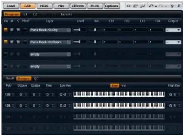
The Program page is divided into two sections. The upper section can be used to load and save layers, and to set up the mix parameters such as level, pan and FX sends. The lower section can display the layer ranges, the program FlexPhraser editor or the quick control assignments.
The upper section

On
The On switch can be used to turn on and off a layer. Layers that are set to off are still loaded but do not use any processing power.
Mute
Enable the Mute button to turn off a layer. The program remains loaded and continues to be processed and can therefore be turned on again smoothly.
Solo
Enable the Solo button in order to hear only the respective layer. You can also enable multiple Solo buttons.
FlexPhraser
Here you can activate the FlexPhraser of a layer. The Flex-Phraser editor itself can be found on the corresponding layer editor page.
Level
Here you can you can adjust the loudness of the layer. The control range is from -∞ dB to +12 dB.
Pan
Here you can set the position of the layer in the stereo panorama. The control range is from hard left (-100%) to hard right (+100%).
FX1-4 send levels
These four sliders adjust the send levels for the global AUX FX busses for each layer separately. The control range is from -∞ dB to 0 dB.
Output
Here you can select the output for each layer separately. If you do not want the signal to be sent to the output that is specified for the program, you can select the Main or one of the 15 individual plug-in outputs instead.
Loading layers
To load a layer:
- Click the triangle button on the left side or right-click the layer name field, open the context menu and select "Load Layer" to open a MediaBay dialog.
- Double-click the desired layer preset to load it.
- Click OK to close the dialog and to confirm your preset selection.
- Click Cancel to abort the loading process and to revert to the original layer.
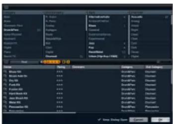
⇒ You can use the MediaBay dialog in the same way as the MediaBay view on the Load page. For detailed information please refer to the section "MediaBay" on page 87.
Aborting the loading of layers
Some layer presets use large sample data and therefore need a certain amount of time to load completely. In this case, a progress bar is shown directly in the layer slot. In addition, the Load buttons change to "Abort" buttons (x) that allow you to stop the loading process and to reset the slot to its previous state.
Saving layers
To save a layer:
- Right-click the layer name field to open the context menu.
- Select "Save Layer" to open the Save Preset dialog.
- Name the preset and set tags.
- Click OK to save the preset and close the dialog.
For more details on tagging please refer to the section "MediaBay" on page 87.
Renaming layers
To change the name of layer:
- Double-click the layer name field.
- Enter the desired name.
- Press Enter or click somewhere outside the name field.
⇒ Unless you save the layer as a layer preset, the layer name only remains an internal setting that helps you organizing multiple layers. Executing a save operation suggests the name given in that field.
Clearing layers
To remove a layer:
- Click the layer name field to open the context menu.
- Select "Clear Layer".
Copying and pasting layers
Complete layers can be copied from one layer slot to another. This can be done inside a program, from one program to another or even from one plug instance to another.
To copy a layer:
- Right-click the layer name field to open the context menu.
- Select "Copy Layer".
- Right-click the layer name field where you want to insert the copy.
- Select "Paste Layer" in the context menu.
Layer ranges subpage

Poly (phony)
This setting is used to specify how many notes can be played at the same time.
⇒ Unlike all the rest of the parameters of the Program page, the Polyphony setting is part of the layer settings and therefore restored when you load a layer.
When a layer is defined as monophonic sound, the setting will not have any influence.
Octave
You can shift the octave of a layer by +/- 4octaves.
Coarse (Tune)
You can shift a layer by +/- 12 semitones.
Fine (Tune)
You can detune a layer by +/- 100 cents.
Key range (Low Key, High Key)

Each slot can be limited to a certain key range. You can set the range by using the text faders for Low and High Key or by dragging the keyboard range control at its ends. Dragging the keyboard in the middle moves both values at the same time. As an additional option you can use the MIDI input to set the range. Click the desired text field and play the note.
Velocity range (Low Key, High Key)

Each slot can be limited to a velocity range. You can set the range by using the text faders for Low and High Vel or by dragging the graphical velocity range control at its ends. Dragging the control in the middle moves both values at the same time. To switch between velocity and key range use the Key/Vel switches above the range controls.
Editing layers
A program contains up to four layers. Each layer can be edited separately.
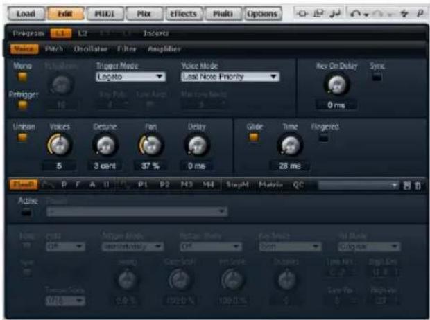
Layer editor
To edit a layer:
- In the Multi Program Rack, select the program that contains the layer you want to edit.
- Click Edit to open the Edit page.
- With the page buttons at the top of the Edit page, select the layer you want to edit, i.e. Layer 1, Layer 2, Layer 3 or Layer 4.
Depending on the layer type, the respective editor (synth, sample, instrument, drum or loop editor) opens.
Accessing the parameters of layers
The layer editor is divided into an upper and a lower part. The upper and lower parts display the different parameters of the layer.
To access the parameters of a layer:
- Select the layer you want to edit.
- In the upper or lower part, click the page button of the section, such as Pitch, Filter, Amp, etc. that you wish to access.
Voice page
The Voice page of the synth and sample layers gives you access to voice settings of the layer which allows you to control the various Polyphony parameters, Trigger and Voice modes. You can furthermore configure the Unison feature and set the Glide. In addition, there is a Key On Delay to delay the notes you play as well.
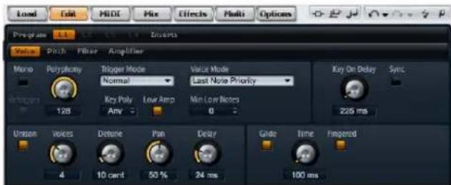
Voice page
To access the Voice page:
- Go to the Edit page and select the synth or sample layer you want to adjust.
- In the upper section of the editor, click the Voice page button.
Mono
Here you can switch between monophonic and polyphonic playback:
- Activate "Mono" to switch to monophonic playback. Usually, this allows a more natural sounding performance for solo instruments.
- Deactivate "Mono" to play polyphonically with the number of notes specified by the Polyphony setting.
Retrigger
This option allows the retriggering of a stolen note while Mono is active. When Mono and Retrigger are activated, a note that was stolen by another one will be retriggered if you still hold the stolen note while you release the new one. For example, with Mono and Retrigger activated, you can play trills by holding one note and pressing/releasing another note repeatedly very fast.
Polyphony
Use this parameter to set an upper limit for the number of notes you can play in "Poly" mode. You can set Polyphony between 2 and 128 notes.
If, for example, the program has a smaller value for polyphony than the contained layers, the maximum number of notes you can play will be limited by the setting of the program.
Key Poly
Key Poly is short for Key Polyphony. With this parameter you can set an upper limit for the number of notes you can play per key. The last played notes have priority over the previously played notes of the same key. "Poly" mode needs to be active to make this parameter effective. The control range is from 1 to 32.
Key Polyphony works within the limits of the Polyphony setting. The lower of the two settings will be given priority.
Low Amp
When notes are stolen due to a Key Poly limitation, the oldest note is removed first by default. By activating Low Amp the note with the lowest amplitude will be removed instead.
Trigger mode
To avoid discontinuities during playback of envelopes and samples, you can select one of three different characteristics for triggering notes:
Normal
"Normal" triggers a new note when stealing the previous note, which includes the envelopes being triggered from the start. A sample of a sample zone will also be triggered from the start. To minimize discontinuities set the Voice Fade Out parameter of the zone accordingly.
Resume
"Resume" does not trigger a completely new note: If the new note stays within the same zone, the envelopes re-trigger but resume at the level of the stolen note and the pitch of the zone will be set to the new note. If the new note plays in a different zone, the new note will play from the start including any envelopes and samples.
Legato
“Legato” does not trigger a completely new note: If the new note plays within the same zone (sample), the envelopes keep running and the pitch of the zone will be set to the new note. If the new note plays in a different zone, the new note will play from the start including any envelopes and samples.
Voice mode
The Voice mode specifies the conventions for stealing notes in playback and if new notes are being triggered when the Polyphony setting is exceeded. The stealing and triggering of notes depends on the selected Voice mode and your keyboard play. You can select one of the following Voice modes:
Last Note Priority
This mode guarantees the playback of the last played notes by stealing the first played notes (First In, First Out). New notes have priority over older notes.
- If you exceed the maximum number of notes, the first played notes will be stolen in their chronological order to make space for the last played notes.
First Note Priority
This mode guarantees the playback of the first played notes. Older notes have priority over new notes.
- If you exceed the maximum number of notes while the first played notes are still being held, no notes will be stolen. New notes will not be triggered until a voice is free.
Low Note Priority
This mode guarantees the playback of low notes. Low notes have priority over high notes.
- If you exceed the maximum number of notes by playing a higher note than the held ones, no note will be stolen and no new note will be triggered.
- If you exceed the maximum number of notes by playing a lower note than the held ones, the highest note will be stolen and the new note will be triggered.
High Note Priority
This mode guarantees the playback of high notes. High notes have priority over low notes.
- If you exceed the maximum number of notes by playing a lower note than the held ones, no note will be stolen and no new note will be triggered.
- If you exceed the maximum number of notes by playing a higher note than the held ones, the lowest note will be stolen and the new note will be triggered.
Stealing Lowest Amplitude
This mode guarantees the playback of the last played notes by stealing the notes with the lowest amplitudes. Notes with high amplitude have priority over notes with low amplitude.
- If you exceed the maximum number of notes, the note with the lowest amplitude will be stolen to make space for the last played note.
Stealing Released Notes
This mode steals notes that play in release first. Notes that are being held have priority over notes that play in release. If no note plays in release, the oldest note will be stolen instead.
- If you exceed the maximum number of notes, the oldest note that plays in release will be stolen to make space for the last played note.
- If no note is playing in release and you exceed the maximum number of notes, the first played notes will be stolen in their chronological order to make space for the last played notes.
Key On Delay
With this feature you can delay the playback of the layer by an adjustable time or a note value.
Delay Time
When you play a note, the playback of the layer will be delayed by the time or note value you set with this parameter. With Sync deactivated, the delay is specified in milliseconds. The control range is from 0 ms to 5000 ms. With Sync activated, the delay is specified in fractions of beats. The control range is from 1/256 to 8/4.
Sync
To synchronize the delay time to the host tempo, activate this option.
Unison
Unison allows you to trigger multiple voices simultaneously with each note you play.
Active
Use this option to turn the Unison feature on or off.
Voices
By default, Voices has a value of 2. Setting higher values increases the number of voices being triggered simultaneously. For a richer sound, adjust the Detune, Pan and Delay parameters accordingly. The control range is from 2 to 8 voices.
Detune
Use this to detune the pitch of each Unison voice by the amount specified in cents. The control range is from 0 to 100 cents. Detuning pitch of the voices results in a fatter sound.
Pan
Use this to spread the Unison voices across the stereo panorama. The control range is from 0% to 100%. The higher the value, the broader the stereo image will be.
Delay
With this parameter you can adjust a small random delay for each Unison voice. The control range is from 0% to 100%. With a value of 0% all unison voices will be triggered at the same time. Values from 1% to 100% add a small random delay to each unison voice and the voices will not be triggered at the same time anymore. The higher the value the more random the delay will be. This is especially useful to avoid comb filter effects with two or more slightly detuned samples, which would occur if you play them back at exactly the same time.
Glide
You can use Glide to bend the pitch between notes that follow each other. This comes best into effect with Mono mode enabled. However, Glide also works polyphonically.
Glide Active
Use this option to turn the Glide feature on or off.
Glide Time
This specifies the time needed to bend the pitch from one note to the other. You can set a time between 1 ms and 5000 ms.
⇒ If you use Cutoff, Amplitude and Pan Key Follow, the cutoff, amplitude and pan will change with the Glide effect as well.
Fingered
Activate Fingered to glide the pitch only between legato played notes.
Pitch page
The Pitch page of synth and sample layers gives you access to the tuning of the layer.
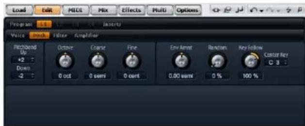
To access the Pitch page:
- Go to the Edit page and select the synth or sample layer you want to adjust.
- In the upper section of the editor, click the Pitch page button.
Tune section
The Tune section gives you access to the tuning of the layer. With the Octave, Coarse and Fine parameters, you can adjust the tuning in steps of octaves, semitones and cents. In addition, you can adjust the amount of pitch modulation from the Pitch Envelope, the keyboard or randomly with each keystroke. Furthermore, you can set the pitch bend range for the up and down direction of the pitch bend wheel separately.
Octave
Here you can adjust the pitch in octave steps. The control range is from -5 to +5 octaves.
Coarse
Here you can adjust the pitch in semitone steps. The control range is from -12 to +12 semitones.
Fine
This parameter tunes the pitch in hundredths of a semi-tone (cents). The control range is from -100 to +100 cents.
Env Amnt
Env Amnt is short for Envelope Amount. This parameter determines how much the pitch is affected by the Pitch Envelope. The control range is from -48.00 to +48.00 semitones.
Bypass Envelope
To play the layer without the modulation from the Pitch Envelope, click the envelope bypass button at the upper right in the title bar of the section.
Random
This parameter allows you to offset the pitch with each played note randomly. The amount of pitch randomization can be adjusted within a control range from 0% to 100%. Higher values cause stronger variations. At a setting of 100% the random offsets can vary from -6 to +6 semitones.
Key Follow
Here you can adjust the pitch modulation from MIDI note number. The control range is from -200% to +200%. Set this parameter to positive values in order to raise the pitch the higher you play. Use negative values to lower the pitch the higher you play. The pitch follows exactly the played note at a setting of +100%.
Center Key
This specifies the MIDI note around which the Pitch Key Follow pivots. The range extends from C-2 to G8.
Pitch Bend Up
Here you can set the range of the pitch modulation when moving the pitch bend wheel up. The control range is from -48 to +24 semitones.
Pitch Bend Down
Here you can set the range of the pitch modulation when moving the pitch bend wheel down. The control range is from -48 to +24 semitones.
Oscillator page
The Oscillator page of the synth layer offers six sound sources: Three main oscillators, the suboscillator, the ring modulation and the noise generator. To create interesting electronic spectra, you can mix any of these sound sources. The resulting signal is sent to the Filter and Amplifier sections for further sound shaping.
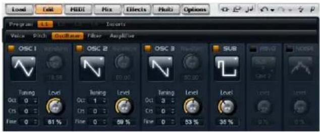
To access the Oscillator page:
-
Go to the Edit page and select the synth layer you want to adjust.
-
In the upper section of the editor, click the Oscillator page button.
Oscillator 1/2/3
The three main oscillators, OSC 1, OSC 2 and OSC 3, offer different wave shapes and algorithms. Select the wave shape and algorithm with the oscillator type (see below).
OSC 1/2/3 Active
Use this to activate the oscillators 1, 2 and 3 respectively.
Please make sure to switch off the oscillators when the function is not needed. When kept on, they use CPU cycles even if they are not heard, such as in a situation where the level set to 0%.
OSC 1/2/3 Type
This selects the basic sound character of the oscillator. The oscillator type first lists the wave shape (Sine, Triangle, Saw or Square), followed by the type of algorithm (PWM, Sync, CM or XOR). Depending on the selected algorithm, there is a waveform parameter that controls how the oscillator sounds.
The waveform parameters of OSC1, OSC2 and OSC3 can be assigned as modulation destinations in the Modulation Matrix.
The following algorithms are available:
Algorithm Description
PWM PWM is short for pulse width modulation. PWM is only supported by the square wave shape. The waveform parameter sets the ratio between the high and low of the square wave. A setting of 50% produces a pure square wave. With settings below or above 50% the oscillator produces rectangular waves.
Sync Sync is short for synchronization. This algorithm provides different hard-sync oscillators where each is a combination of a master and slave oscillator. The wave shape of the slave oscillator (Sine, Triangle, Saw or Square) is reset with each full wave cycle of the master oscillator. This means that a single oscillator can already produce a rich sync-sound without utilizing other oscillators as slave or master. The waveform parameter adjusts the pitch of the slave oscillator producing the typical sync-sound.
CM CM is short for cross modulation. This algorithm provides a combination of two oscillators where a master oscillator is modulating the pitch of a slave oscillator (Sine, Triangle, Saw or Square) at audio rate. The waveform parameter adjusts the pitch ratio between slave and master oscillator resulting in a sound close to frequency modulation.
XOR XOR is short for "exclusive or". This algorithm compares two square waveforms with an XOR operation. Depending on the outcome of the XOR operation, the wave shape of a third oscillator (Sine, Triangle, Saw or Square) is reset. The waveform parameter adjusts the pitch ratio of the square oscillators resulting in a sound close to ring modulation of the third oscillator.
⇒ Except for PWM, all algorithms support the Sine, Triangle, Saw and Square wave shapes. PWM supports Square wave only.
To select an oscillator type:
-
In the section of OSC1, OSC2 or OSC3, click the icon that indicates the wave shape.
-
From the menu, select the oscillator type to set the wave shape and algorithm you want to use.
OSC 1/2/3 Waveform
The waveform parameter allows you to modify the sound of the oscillator algorithm. Its effect depends on the selected oscillator type (see above for details).
OSC 1/2/3 Octave (Oct)
Here you can adjust the pitch in octave steps. The control range is from -4 to +4 octaves.
OSC 1/2/3 Coarse (Crs)
Here you can adjust the pitch in semitone steps. The control range is from -12 to +12 semitones.
OSC 1/2/3 Fine
This parameter tunes the pitch in hundredths of a semi-tone (cents). The control range is from -100 to +100 cents.
OSC 1/2/3 Level
This adjusts the output level of the oscillator. The control range is from 0 to 100%.
⇒ The waveform, pitch and level of oscillator 1, 2, and 3 can be modulated separately in the Modulation Matrix.
Sub Oscillator
The pitch of the Sub Oscillator is always one octave lower than the overall pitch of the synth layer. If you modulate the Pitch of the synth layer, the pitch of the Sub Oscillator follows.
Sub Active
Use this to activate the Sub Oscillator.
⇒ Please make sure to switch off the Sub Oscillator when the function is not needed. When kept on, they use CPU cycles even if they are not heard, such as in a situation where the level set to 0% .
Sub Oscillator Type
Here you can select the wave shape of the Sub Oscillator. You can choose between Sine, Triangle, Saw, Square, Pulse Wide and Pulse Narrow.
Sub Level
This adjusts the output level of the Sub Oscillator. The control range is from 0 to 100%.
Ring Modulation
Ring Modulation (RM) produces the sums and the differences between the frequencies of two signals.
RM Active
Use this to activate the Ring Modulation.
⇒ Please make sure to switch off the Ring Modulation when the function is not needed. When kept on, it uses CPU cycles even if the Ring Modulation is not heard, such as in a situation where the level set to 0% .
RM Source 1/2
This allows you to select the sources that will be ring modulated. You can select OSC1 or Sub as Source 1 and OSC2 or OSC3 as Source 2. Make sure the respective oscillators are activated when you select them. Otherwise, you will not hear any sound.
RM Level
This adjusts the output level of the Ring Modulation. The control range is from 0 to 100%.
Noise
Noise is used for non-pitched sounds. In addition to standard white and pink noise, there are also band pass filtered (BPF) versions of white and pink noises.
Noise Active
Use this to activate the noise generator.
⇒ Please make sure to switch off the noise generator when the function is not needed. When kept on, it uses CPU cycles even if the noise is not heard, such as in a situation where the level set to 0% .
Noise Type
Here you can select the sound color of the noise. You can either select White, Pink, White BPF or Pink BPF.
Noise Level
This adjusts the output level of the noise generator. The control range is from 0 to 100%.
⇒ The Sub Level, RM Level and Noise Level can be modulated separately in the Modulation Matrix.
Filter page
The Filter page of synth and sample layers offers settings to adjust the tone color of the sound. Filters shape the harmonic content of a sound by removing or accenting frequencies in the spectrum. HALion Sonic's filter section is extremely versatile and powerful. With filter type you can select the basic sound character of the filter, either with or without Distortion. This feature is also useful to scale the CPU consumption since filters without Distortion use less CPU cycles. With filter mode you can configure the filter section as a single filter, two filters in parallel or serial connection, or as a morphing filter that allows you to blend between up to four different filter shapes.
In general, filters are identified by their pass-band and amount of attenuation. The Cutoff frequency separates the pass-band from the stop-band. Frequencies in the pass-band stay unprocessed, while frequencies in the stop-band will be attenuated or removed. The amount of attenuation is specified in decibels per octave (dB/oct). For example, a 12dB/oct low-pass filter attenuates the high frequencies at 12dB for each octave above the Cut-off frequency. Other typical filter types are high-pass, band-pass and band-reject. Another type of filter is called all-pass. As its name suggests, it does not attenuate frequencies. Instead, it shifts the phase of the signal. When mixed with the original signal, certain frequencies will be attenuated again. For example, the phase shifter would use this.
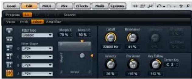
To access the Filter page:
-
Go to the Edit page and select the synth or sample layer you want to adjust.
-
In the upper section of the editor, click the Filter page button.
Filter type
By selecting the filter type you specify the basic sound character of the filter. HALion Sonic offers up to 23 filter shapes (for details on filter shapes, see below).
Filter type Description
Off The filter section is switched off. Use this when no filter is needed for your sound and/or when you want to save CPU cycles.
Classic This filter type offers 23 filter shapes with Resonance.
Tube Drive This filter type offers a lot of character by adding warm, tube-like distortions. It comes with 23 filter shapes, adjustable Resonance and Distortion.
Filter mode
This parameter allows you determine the overall filter structure. The filter types Classic and Tube Drive provide the following options:
Filter mode Description
Single This mode uses one filter with one selectable filter shape. You can select any of the 23 filter shapes.
Dual Serial This mode uses two separate filters connected in series. You can select any of the 23 filter shapes for each filter independently. The parameters Cutoff and Resonance control both filters simultaneously. However, you can offset the cutoff and resonance of the second filter with the parameters CF Offset and Res Offset.
Dual Parallel This mode uses two separate filters connected in parallel. You can select any of the 23 filter shapes for each filter independently. The parameters Cutoff and Resonance control both filters simultaneously. However, you can offset the cutoff and resonance of the second filter with the parameters CF Offset and Res Offset.
Morph 2 This mode morphs between filter shape A and B. You can select any of the 23 filter shapes for filter shape A and B independently. Adjust the morphing with the Morph Y parameter.
Morph 4 This mode morphs sequentially from filter shape A to D. You can select any of the 23 filter shapes for filter shape A, B, C and D independently. Adjust the morphing with the Morph Y parameter.
Morph XY This mode morphs freely between the filter shapes A, B, C and D. In other words, the morphing can be any mix between the four filter shapes. You can select any of the 23 filter shapes for filter shape A, B, C and D independently. Adjust the morphing with the Morph X and Morph Y parameters.
Filter shape
Each filter type offers 23 different filter shapes. By selecting the filter shape you determine which frequencies will be affected. The letters and numbers indicate the filter shape: For example, LP12 is short for low-pass 12dB/oct. Depending on the chosen filter mode, you can either select one, two or four shapes.
Filter shapes
The filter types Classic and Tube Drive offer the following filter shapes:
Filter shape Description
| LP24 Low-pass filter with 24 dB/oct. Frequencies above the Cutoff will be attenuated. |
| LP18 Low-pass filter with 18 dB/oct. Frequencies above the Cutoff will be attenuated. |
| LP12 Low-pass filter with 12 dB/oct. Frequencies above the Cutoff will be attenuated. |
| LP6 Low-pass filter with 6 dB/oct. Frequencies above the Cutoff will be attenuated. |
| BP12 Band-pass filter with 12 dB/oct. Frequencies below and above the Cutoff will be attenuated. |
| BP24 Band-pass filter with 24 dB/oct. Frequencies below and above the Cutoff will be attenuated. |
| HP6+LP18 High-pass filter with 6 dB/oct. plus low-pass filter with 18 dB/oct. (asymmetric band-pass filter). Frequencies below and above the Cutoff will be attenuated. The frequencies above will fall off stronger. |
| HP6+LP12 High-pass filter with 6 dB/oct. plus low-pass filter with 12 dB/oct. (asymmetric band-pass filter). Frequencies below and above the Cutoff will be attenuated. The frequencies above will fall off stronger. |
| HP12+LP6 High-pass filter with 12 dB/oct. plus s low-pass filter with 6 dB/oct. (asymmetric band-pass filter). Frequencies below and above the Cutoff will be attenuated. The frequencies below will fall off stronger. |
| HP18+LP6 High-pass filter with 18 dB/oct. plus s low-pass filter with 6 dB/oct. (asymmetric band-pass filter). Frequencies below and above the Cutoff will be attenuated. The frequencies below will fall off stronger. |
| HP24 High-pass filter with 24 dB/oct. Frequencies below the Cutoff will be attenuated. |
| HP18 High-pass filter with 18 dB/oct. Frequencies below the Cutoff will be attenuated. |
| HP12 High-pass filter with 12 dB/oct. Frequencies below the Cutoff will be attenuated. |
| HP6 High-pass filter with 6 dB/oct. Frequencies below the Cutoff will be attenuated. |
| BR12 Band-reject filter with 12 dB/oct. Frequencies around the Cutoff will be attenuated. |
Filter shape Description
| BR24 Band-reject filter with 24 dB/oct. Frequencies around the Cutoff will be attenuated. |
| BR12+LP6 Band-reject filter with 12 dB/oct. plus low-pass filter with 6 dB/oct. Frequencies around and above the Cutoff will be attenuated. |
| BR12+LP12 Band-reject filter with 12 dB/oct. plus low-pass filter with 12 dB/oct. Frequencies around and above the Cutoff will be attenuated. |
| BP12+BR12 Band-pass filter with 12 dB/oct. plus band-reject filter with 12 dB/oct. Frequencies below, above and around the Cutoff will be attenuated. |
| HP6+BR12 High-pass filter with 6 dB/oct. plus band-reject filter with 12 dB/oct. Frequencies below and around the Cutoff will be attenuated. |
| HP12+BR12 High-pass filter with 12 dB/oct. plus band-reject filter with 12 dB/oct. Frequencies below and around the Cut-off will be attenuated. |
| AP All-pass filter with 18 dB/oct. Frequencies around the Cutoff will be attenuated. |
| AP+LP6 All-pass filter with 18 dB/oct. pl us low-pass filter with 6 dB/oct. Frequencies around and above the Cutoff will be attenuated. |
| HP6+AP High-pass filter with 6 dB/oct plus all-pass filter with 18 dB/oct. Frequencies around the Cutoff will be attenuated. |
Cutoff
Here you can adjust the Cutoff frequency of the filter. The control range is from 20 Hz to 22.000 Hz. The effect depends on the filter type you have selected.
Resonance
This parameter emphasizes the frequencies around the cutoff. The control range is from 0% to 100%. For an electronic sound, increase the Resonance. At higher settings of Resonance the filter will self-oscillate, which delivers a ringing tone.
X/Y control
The X/Y control allows you to adjust two parameters simultaneously. This is especially useful with the morphing filters where the X/Y control adjusts the blend between the filter shapes. For the other filter modes, the X/Y control adjusts Cutoff and Resonance. Depending on the selected filter type, the X/Y control adjusts different parameters:
Selected filter Description
| Single, Dual Serial & Dual Parallel | The X/Y control adjusts the Cutoff frequency on the horizontal and the Resonance on the vertical axis. |
| Morph 2 and 4 The X/Y control adjusts the morphing between the filter shapes on the vertical (Morph Y) axis. The horizontal axis adjusts the Cutoff frequency. |
| Morph XY The X/Y control adjusts the morphing between the filter shapes AD and BC on the horizontal (Morph X) and AB and DC on the vertical axis (Morph Y). |
Env Amnt
Env Amnt is short for Envelope Amount. Use this parameter to adjust the Cutoff modulation from the Filter Envelope. The control range is from -100% to +100%. Setting negative values inverts the direction of the modulation from the Filter Envelope.
Velocity
This parameter adjusts the Cutoff modulation from velocity. It ranges from -100% to +100%. Set this parameter to positive values to increase the Cutoff with higher velocities. Use negative values to decrease the Cutoff with higher velocities.
Distortion
This parameter adds a warm, tube-like filter distortion to the signal. The control range is from 0% to 100%. At higher settings, it allows a very intense distortion effect.
⇒ Thisparameter is only available for the Tube Drive filter type.
CF Offset
CF is short for cutoff frequency. For the dual filters, this parameter allows you to offset the cutoff frequency of the second filter (filter shape B). The control range is from -100% to 100%.
Res Offset
Res is short for resonance. For the dual filters, this parameter allows you to offset the resonance of the second filter (filter shape B). The control range is from -100% to 100%.
Key Follow
Here you can adjust the Cutoff modulation from note number. The range is from -200% to +200%. Set this parameter to positive values to raise the Cutoff with notes above the Center Key. Use negative values to lower the Cutoff with notes above the Center Key. At +100% the Cutoff follows exactly the played pitch.
Center Key
This parameter sets the note around where the Key Follow pivots. It ranges from C-2 to G8.
Amplifier page
The Amplifier page of synth and sample layers gives you access to the level and pan settings of the layer. With level you adjust the loudness of the layer. With pan you specify the position of the layer in the stereo panorama. Both level and pan can be modulated from MIDI note number. In addition, the pan position can be modulated with each keystroke randomly or left-right/right-left in alternation.
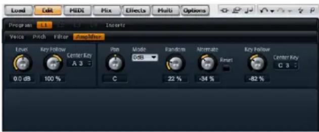
To access the Amplifier page:
- Go to the Edit page and select the synth or sample layer you want to adjust.
- In the upper section of the editor, click the Amplifier page button.
Level
Here you can you can adjust the loudness of the layer. The control range is from -∞ dB to +12 dB.
Key Follow
Here you can scale the loudness across the MIDI keyboard. The control range is from -200% to +200%. Set this parameter to positive values to raise the loudness the higher you play. Use negative values to lower the volume the higher notes you play.
Center Key
This specifies the MIDI note around where the Key Follow pivots. The range extends from C-2 to G8.
Pan
Here you can set the position of a sound in the stereo panorama. The control range is from hard left (-100%) to hard right (+100%).
Mode
With this option you can specify how the loudness changes across the stereo panorama. You can select between the four modes 0 dB, -3 dB, -6 dB and Off:
- The 0dB option works like a balance control: Setting the pan control towards the left fades out the right channel and vice versa. At the center position, the loudness is not cut.
- The -3dB option uses the cosine/sine pan law: The loudness is cut by -3dB at the center position, but the energy is preserved when moving the source signal across the stereo panorama. The -3dB option sounds more natural. The transition from hard left to hard right sounds much smoother than with the 0dB or the -6dB setting.
- The -6dB option uses the linear pan law: The loudness is cut by -6dB at the center position, and the energy is not preserved when moving the source signal across the stereo panorama. The -6dB option sounds more synthetic. The transition from hard left to hard right sounds more abrupt than with the -3dB setting.
- When set to "Off" no loudness correction is applied when a signal is panned across the stereo panorama.
Random
This parameter allows you to offset the pan position with each played note randomly. The strength of the randomization can be adjusted within a range from 0% to 100%. Higher values cause stronger variations. At a setting of 100% the random offsets can vary from fully left to fully right.
Alternate
This parameter allows you to alternate the pan position each time you play a note. For example, a value of +100% means the first note plays hard right, the second note hard left, and so on. You can specify the pan position for the first time when you hit a note with the algebraic sign: For negative values the initial pan position will be left and for positive values it will be right. With the value in percent you determine the deviation across the stereo panorama. The control range is from -100% to +100%.
Reset
The initial pan position is set once after HALion Sonic is loaded. Then, HALion Sonic counts each note you played to determine the next pan position. To reset this counter, click the Reset button next to the Alternate control.
Key Follow
Here you can adjust the pan modulation from MIDI note number. The control range is from -200% to +200%. Set this parameter to positive values to offset the pan position towards the right for notes above and towards the left for notes below the Center Key. Use negative values to offset the pan position towards the left for notes above and towards the right for notes below the Center Key. At the maximum setting of +200% the pan position moves from hard left to hard right within two octaves: Fully left is reached one octave below and fully right is reached one octave above the center key.
Center Key
This specifies the MIDI note around where the Pitch Key Follow pivots. The range extends from C-2 to G8.
Envelope pages
The envelope pages of the synth and sample layers give you access to the four envelopes of the layer, i.e., Pitch (P), Filter (F), Amp (A) and User (U) envelope. Each of these is a multi-segment envelope with up to 128 nodes. The nodes specify the overall shape of the envelope with their Time, Level and Curve parameters. The times and levels of the envelope can be modulated from velocity. The Key Follow parameters modulates the times via MIDI note number. Curve allows you to adjust the curvature between two nodes from linear to logarithmic or exponential behavior. The Sync option allows you to synchronize the envelope times to the tempo of your host application and you can setup a loop between two definable nodes. You can select a second envelope that is displayed in the background of the edited envelope, serving you as an optical or snap reference.
The envelopes Amp, Filter and Pitch are pre-assigned to Amplitude, Filter Cutoff Frequency and Pitch of the layer. You can adjust the pre-assigned modulations in the according section of the layer. The purpose of the User Envelope is freely definable. You can select the User Envelope as a source in the Modulation Matrix. However, you can also use the envelopes Amp, Filter and Pitch as sources in the Modulation Matrix as well.
To access the envelopes:
- Go to the Edit page and select the synth or sample layer you want to adjust.
- In the lower section of the editor, click the page button of the respective envelope.
- A: Click "A" to display the parameters of the amplifier envelope. The amplifier envelope shapes the volume over time.
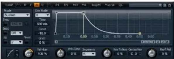
- F: Click "F" to display the parameters of the filter envelope. The filter envelope controls the Cutoff Frequency of the Filter to shape the harmonic content over time.
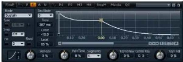
- P: Click "P" to display the parameters of the pitch envelope. The pitch envelope modulates the pitch over time. The pitch envelope is bipolar, which means it allows for negative and positive values to bend the pitch up and down.
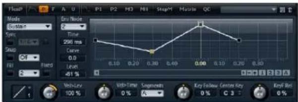
- U: Click "U" to display the parameters of this free assignable user envelope. It is bipolar, which means it allows for negative and positive values, for instance, to modulate the pan from left to right.
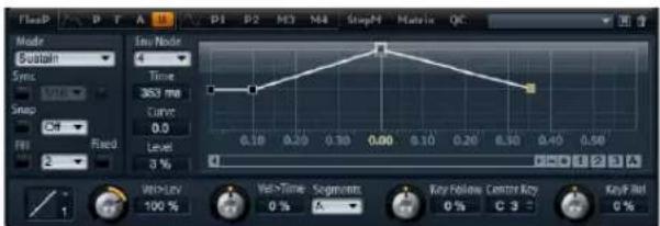
Presets
Presets for different envelopes can be loaded and saved in the upper right of the lower section of the layer editor.
- To load a preset, click on the preset loader and select the desired preset from the menu that pops up.
- To delete a preset from your system, click the trash bin button. Then, you will be asked to confirm the deletion.
- To save a new preset, click the floppy disk button. A file dialog opens where you can name and save your preset file.
Navigating in the graphical envelope editor
The vertical axis of the graphical envelope editor displays level. The horizontal axis displays time. For fine editing the times of the envelope, use the scroll bar below the graphical editor to zoom in on the horizontal axis:
Zooming
- To zoom in, click the "+" button to the right of the scroll bar.
- To zoom out, click the "-" button to the right of the scroll bar.
- Drag the time line up or down to zoom in or out at the position that you clicked.
- To zoom to a certain region, hold [Alt] and drag the mouse over the region.
Scrolling
- Drag the scroll bar to the left or right to scroll the envelope editor to the desired position.
- Click on an empty space next to the scroll bar to jump to the according position in the envelope editor.
- Click on the triangles left and right of the scroll bar to scroll the envelope stepwise.
Envelope zoom snapshots
Envelope zoom snapshots save the current state of the graphical envelope editor. For example, by saving two envelope zoom snapshots, one for the beginning and one for the end of the envelope, you can conveniently switch between editing the attack and release of the envelope.
Saving and loading envelope zoom snapshots
To the right of the scroll bar you find three numbered buttons which allow you to save and load envelope zoom snapshots for the current envelope editor (Amp, Filter, Pitch, or User). When saving an envelope zoom snapshot, it remembers the zoom factor and scroll position of the graphical envelope editor. The zoom factor and scroll position will be restored when loading the envelope zoom snapshot.
- To save the current state of the graphical envelope editor, hold [Shift] and click one of the numbered buttons to the right of the scroll bar.
- To load a previously saved envelope zoom snapshot, click on the according numbered button. The button changes its color to green indicating the snapshot is active. Zooming or scrolling with the graphical envelope editor deactivates the Envelope Zoom Snapshot. The button indicates this by turning grey.
Editing the envelope
Each multi-segment envelope has up to 128 nodes with the Time, Level and Curve parameters. The nodes and their parameters specify the overall shape of the envelope. You can edit one or multiple nodes by using the graphical envelope editor or by typing in values from keyboard. Before you can edit nodes, you must select them:
Selecting nodes
- Select a node by clicking the node in the graphical editor. Selected nodes turn light blue in color. The focused node is indicated by an orange frame color. The focused node displays its parameters in the text fields to the left of the graphical envelope editor.
- With multiple nodes selected, use the Node pop-up menu above the text fields to set the focus on a different node without losing the current selection.
- Hold [Shift] and click on a node to add it to the selection. Selected nodes will be edited together.
- In addition, you can select multiple nodes by drawing a rectangle with the mouse around the desired nodes.
- With a single node selected, use the left or right arrow key to select the next or previous node. In a multi-selection, the focused node will change instead and the previous or next node within the multi-selection will be focused.
- Click on an empty space in the background of the envelope to cancel the current selection.
Adjusting Time
Time specifies the duration between two nodes. The change in level from the selected to the following node will be carried out in the duration set by Time (0 ms - 30.000 s). Depending on the Sync mode, the parameter Time is displayed in milliseconds and seconds, or fractions of beats (when Sync is activated).
Adjusting the Time parameter with the graphical envelope editor:
- In the graphical envelope editor, select the node(s) you want to edit and drag them left or right. Drag the node(s) left to decrease and right to increase the time(s).
- For a higher resolution, hold [Shift] while moving the node(s).
- Hold [Ctrl] (Win) / [Command] (Mac) while dragging to limit the movement to the time-axis (horizontal positioning only).
Setting the Time parameter by entering values from keyboard:
- In the graphical envelope editor, select the node(s) you want to edit. Use the Env Node pop-up menu to change the focus if necessary. Enter a value into the Time text field located to the left of the graphical envelope editor. Then, hit [Return].
Adjusting level
Level specifies the amplitude of the envelope at the position set by Time. The Amp and Filter envelopes are unipolar. Therefore, the values for level range from 0% to
+100% (positive values only). The Pitch and User envelopes are bipolar, the values for level range from -100% to +100% (negative and positive values) for these envelopes.
⇒ You can change the polarity of the envelopes in the Modulation Matrix, for instance, to map the range of the Amplifier Envelope (unipolar) to Pan (bipolar). However, the envelopes always display their values with their default polarity.
Adjusting the level parameter with the graphical envelope editor:
- In the graphical envelope editor, select the node(s) you want to edit and drag them up or down. Drag the node(s) down to decrease and up to increase the level(s).
- Hold [Alt] while dragging to limit the movement to the level-axis (vertical positioning only).
- For a higher resolution, hold [Shift] while moving the node(s).
Setting the level parameter by entering values from keyboard:
- In the graphical envelope editor, select the node(s) you want to edit. Use the Env Node pop-up menu to change the focus if necessary. Enter a value into the level text field located to the left of the graphical envelope editor. Then, hit [Return].
Adjusting Curve
Curve allows you to adjust the curvature between two nodes from linear to logarithmic or exponential behavior. The range is from -10 to +10.
Adjusting the Curve parameter with the graphical envelope editor:
- In the graphical envelope editor, drag the curvature of the desired envelope segment up or down. Dragging up adjusts the curvature towards logarithmic, dragging down towards exponential behavior.
- [Ctrl]-click (Win) or [Command]-click (Mac) a curvature to reset it to linear behavior.
Setting the Curve parameter by entering values from keyboard:
- In the graphical envelope editor, select the node(s) you want to edit. Use the Node pop-up menu to change the focus if necessary. Enter a value into the Curve text field located to the left of the graphical envelope editor. Then, hit [Return].
- Positive values of Curve change the curvature towards logarithmic and negative values towards exponential behavior.
Adding and removing nodes
The envelopes Amp, Filter, Pitch, and User can have up to 128 nodes. All nodes added after the sustain node always affect the release stage of the envelope, i.e. after the key is released.
- To add a node, double-click at the position where you want to add the node.
- To remove a node, double-click the node you want to remove.
- [Delete] or [Backspace] removes multiple selected nodes.
→ You cannot remove the first, last or the sustain node.
Adding nodes using the Fill function
The Fill function allows you to add multiple envelope nodes after the currently selected node(s):
- From the pop-up menu located to the right of the Fill button, select the number of nodes you wish to add.
- In the graphical envelope editor, select the node from where you want to add nodes. The new nodes will be inserted after the selected node. If several nodes are selected, the new nodes will be inserted after all selected nodes.
- If the Fixed function is deactivated, the added nodes are placed with the time interval specified by the Time parameter of the currently selected node. If multiple nodes are selected, the interval is specified by the focused node. By activating Sync, you can specify the interval with the Sync note value. For example, if 1/4 is selected, new nodes will be added at exact quarter note intervals.
- If the Fixed function is activated, the added nodes fill the space between the last selected node and the following one.
- Click the "Fill" button and the nodes will be added.
Positioning nodes using the Fixed function
When Fixed is activated, only the selected node(s) will be moved on the time-axis. With Fixed deactivated, nodes that follow the currently edited node(s) will be moved also on the time-axis.
- Click "Fixed" to activate or deactivate the function. Fixed is active when the button is highlighted.
Positioning nodes using the Snap function
You can select a second envelope that is displayed in the background of the edited envelope serving you as an optical or snap reference. Nodes you position with Snap activated will snap to the nodes of the envelope that is shown in the background.
- From the pop-up menu located to the right of the Snap button, select the envelope to be displayed in the background.
- Click "Snap" to activate or deactivate the function. Snap is active when the button is highlighted.
Using Sync
You can synchronize the envelopes to the tempo of your host application. This allows you to set envelope times that relate to musical time intervals (for example 1 bar), regardless of tempo changes made later on.
- Click "Sync" to activate the envelope's synchronization mode. Sync is active when the button is highlighted. A grid spaced in fraction of beats appears in the graphical envelope editor.
- From the pop-up menu located to the right of the Sync button, select a note value. This sets the resolution of the grid, i.e. the minimum note value the nodes will snap to when moved.
For example, if you specify a 1/4 note value, the nodes will snap to 1/4 note steps. If the "T" button is activated, the note values correspond to triplet values.
- The Time text field of a node displays times in fractions of beats. The fraction will always be reduced to the smallest possible value. For instance, "2/16" displays as "1/8".
- Envelope nodes that do not exactly match a note value display the note value which they are closest to.
- Nodes that exactly match a note value are indicated by a red dot inside the handle of the node. This can be useful, for example, when you switch the grid between triplets and normal note values: The triplet nodes still indicate that they match a note value, even if the grid shows normal note values.
You can also enter times by entering note values as fractions of beats:
- Select the node(s) you want to edit.
- Enter a note value as fractions of beats such as "1/4". Type the letter "T" behind the note value to enter triplet note values such as "1/8T".
- Hit [Return].
The selected node(s) will be set to the entered note value.
Envelope mode
You can select one of four Envelope modes to specify how the envelope is played back each time you hit a note.
- Sustain: The envelope plays from the first node to its Sustain. The Sustain level is held as long as you play the note. When you release the note, the envelope continues with the stages behind the Sustain. This mode is ideal for looped samples.
- Loop: The envelope starts playback from the first node to the loop nodes. The loop will be repeated as long as the key is held. The envelope plays the stages behind the Sustain when you release the note. This mode is ideal for adding motion to the Sustain (which would be steady in Normal mode).
- One Shot: The envelope will be played from the first to the last node, even if you release the note. The envelope has no Sustain stage. This mode is ideal for drum samples.
- Sample Loop: This mode allows you to preserve the natural attack of the sample. The decay of the envelope does not start until the sample has reached the sample loop start. Set the second node to the maximum level. Then, use any of the following nodes to shape the decay during the loop phase of the sample. This way, the envelope only affects the level during the loop phase of the sample. The attack of the envelope is still executed.
⇒ The mode Sample Loop is only available for sample layers.
Setting up the loop
The envelope repeats its playback between the nodes you select.
- Set the Envelope mode to "Loop".
-
Adjust the loop with the graphical envelope editor:
-
The loop is indicated by the green region in the graphical envelope editor. You can specify the loop start and end by dragging the borders of the region.
- Drag the left border to the node where the loop should start.
- Drag the right border to the node where the loop should end.
⇒ The loop region can only be setup in the Decay of the envelope, i.e. after the first and before the sustain node.
Level Velocity
Use this parameter to adjust the velocity affecting the level of the envelope. The level of the envelope depends on the setting of this parameter and how hard you hit a note:
Positive values increase and negative values decrease the level of the envelope the harder you hit a note. The control range is from -200% to +200%.
Level Velocity Curve
You can select one of eight curves to specify how the incoming velocity translates to the level of the envelope. The characteristic of each curve is displayed by a small icon.
The menu offers the following mathematical functions for velocity:
- 1 = Linear
- 2 = Squared
■ 3 = Squared Inverse - 4 = 2 Poles Squared
- 5 = 2 Poles Squared Inverse
- 6 = Cubic
- 7 = Quadric
- 8 = dB
- 9 = Logarithmic
- 10 = Constant (127)
Velocity to Time
Use this parameter to adjust the influence of velocity on the times of the envelope. Positive values decrease the times for higher velocity values. Negative values increase the times for higher velocity values. The amount ranges from -100% to +100%. In addition, with Segments you can also select which stages of the envelope will be affected by this parameter.
Segments
From the pop-menu, you can select which stages of the envelope will be affected by the Velocity to Time parameter.
- A: The velocity affects the attack time only.
- A + D: The velocity affects all times until the sustain.
- D: The velocity affects all times until the sustain but without the attack.
- A + R: The velocity affects the attack and the release times.
- All: The velocity affects all times.
Key Follow and KeyF Rel
With Key Follow and KeyF Rel you can scale the envelope times across the keyboard. KeyF Rel is short for Key Follow Release. Key Follow scales all times before the Sustain node. KeyF Rel scales all times after the Sustain node (which equals the Release of the envelope). You can set a Center Key around where the Key Follow and KeyF Rel pivot. The envelope times depend on the position where you play the keyboard and on the according Key Follow setting: Positive values decrease the times for notes above and increase the times for notes below the Center Key; the envelope becomes faster the higher you play. Negative values increase the times for notes above and decrease the times for notes below the Center Key; the envelope becomes slower the higher you play. The control range is from -200% to +200%.
Center Key
Specifies the note number around where the Key Follow and KeyF Rel pivot. The range extends from C-2 to G8.
LFO pages
LFO is short for low frequency oscillator. The synth and sample layers offer four LFOs: LFO1 and LFO2 are polyphonic, LFO3 and LFO4 are monophonic. Polyphonic means the LFOs are calculated per voice allowing for independent modulations with each triggered note. You can use this to create a richer sound, for example, with an independent pitch modulation per note. Monophonic means the LFOs are calculated only once per layer. The same modulation will be sent to all voices simultaneously. Monophonic LFOs are often used for modulations such as tremolo and vibrato. LFO1 to LFO4 can be assigned freely in the Modulation Matrix.
For each LFO you can select from eight different waveforms with an additional shape parameter. Frequency adjusts the speed of the modulation and Phase sets the initial start of the waveform when the LFO is retriggered. In addition, you can synchronize the LFO Frequency to the tempo of the host application. Finally, you can define how the LFO is retriggered playing your keyboard. The polyphonic LFOs have an additional envelope with Fade In, Hold and Fade Out that allows you to shape the modulation intensity over time. Furthermore, the start of the modulation can be delayed.
To access the LFOs:
- Go to the Edit page and select the synth or sample layer you want to adjust.
- In the lower section of the editor, click the respective page button.
- To select one of the polyphonic LFOs, click P1 or P2. This refers to LFO1 and LFO2 in the Modulation Matrix. P is short for polyphonic.
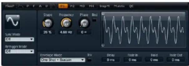
Polyphonic LFO page
- To select one of the monophonic LFOs, click M3 or M4. This refers to LFO3 and LFO4 in the Modulation Matrix. M is short for monophonic.
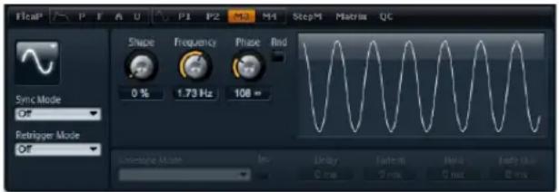
Monophonic LFO page
LFO parameters
LFO waveform and shape
Waveform selects the basic type of waveform. Shape changes the characteristic of the waveform. The control range of shape is from 0% to 100%.
Option Description
| Sine This produces smooth modulation, s tremolo. Shape adds additional harmonics to the wave-form. | Suitable for vibrato or |
| Triangle This is similar in character to Sine. The waveform period-ically ramps up and down. Shape continuously changes the triangle waveform to a trapezoid. | |
| Saw This produces a "ramp" cycle. Shape continuously changes the waveform from ramp down to triangle to ramp up. | |
| Pulse This produces stepped modulation, where the modula-tion switches abruptly between two values. Shape con- tinuously changes the ratio between the high and low state of the waveform. Set shape to 50% to produce a square wave. | |
| Ramp This is similar to the Saw wave form. Shape increasingly puts silence before the sawtooth ramps up. | |
| Log Shape continuously changes the logarithmic curvature from negative to positive. | |
| S & H 1 This produces random stepped modulation, where each step is different. Shape puts ramps between the steps and changes the S&H into a smooth random signal when fully turned right. | |
| S & H 2 This is similar to S & H 1. The steps alternate between random high and low values. Shape puts ramps between the steps and changes the S & H into a smooth random signal when fully turned right. | |
Frequency
This controls the frequency of the modulation, i.e. the "speed" of the LFO. The control range is from 0 Hz to 30 Hz. When Sync is activated, the frequency is set in fractions of beats.
Phase
This sets the initial phase of the waveform when the LFO is retriggered. The control range is from 0° to 360° .
Rnd
Rnd is short for Random. When activated, each note starts with a randomized start phase. The Phase control is automatically disabled.
Sync mode
You can sync the LFO to the tempo of the host application. The behavior of the Frequency parameter changes with the option you select:
Option Description
| Off Select this to adjust the speed of the modulation in Hertz. |
| Tempo + Retrig Select this to adjust the speed of the modulation in fractions of beats, for example, 1/4, 1/8, etc. You can also set dotted and triplet note values. The restart behavior of the LFO depends on the Retrigger setting. |
| Tempo + Beat Select this to adjust the speed of the modulation in fractions of beats, for example, 1/4, 1/8, etc. You can also set dotted and triplet note values. The LFO restarts with the transport of the host and lines up to the beats of the song. The Retrigger setting does not come into effect. |
Retrigger mode
This defines whether or not the LFO is restarted when a note is triggered. The waveform restarts at the position you set with the Phase parameter. The polyphonic and monophonic LFOs offer different Retrigger settings.
The polyphonic LFOs can only switch between Retrigger On and Off:
Option Description
| Off The LFO runs freely. | |
| On The LFO restarts with each note | that is triggered. |
The monophonic LFOs offer the following modes:
Option Description
Off The LFO runs freely.
First Note The LFO restarts when a notes are held.
note is triggered and no other
Each Note The LFO restarts each time a note is triggered.
LFO Envelopes
The following parameters are only available for the polyphonic LFOs, i.e. LFO1 and LFO2.
Delay
Delay determines the delay time between the moment you play a note and the moment the LFO comes into effect. The control range is from 0 ms to 5000 ms.
Fade In
Fade In determines the amount of time for the LFO to fade in after the note has been triggered and the delay time has elapsed. The control range is from 0 ms to 5000 ms.
Hold
Hold determines the amount of time the LFO is running before the Fade Out is carried out. The control range is from 0 ms to 5000 ms.
⇒ Usethe Env modes "One Shot" or "Hold + Fade Out" to activate the Hold time. With all other Env modes, the Hold time is omitted and acts as Sustain.
Fade Out
Fade Out determines the amount of time for the LFO to fade out after the hold time has elapsed or a note has been released. The control range is from 0 ms to 5000 ms.
⇒ Usethe Env mode "One Shot + Sustain" or "Sustain" to deactivate the Fade Out. This avoids changes of the modulation when the note has been released.
Graphical envelope editing
You can adjust the times of the envelope with the graphical editor:
- The first node adjusts the delay time. Drag the node to the left to decrease and to the right to increase the delay.
- The second node adjusts the Fade In time. Drag the node to the left to decrease and to the right to increase the time.
- The third node adjusts the Hold time. Drag the node to the left to decrease and to the right to increase the time.
- The fourth node adjusts the Fade Out time. Drag the node to the left to decrease and to the right to increase the time.
Env Invert
When activated, the behavior of the LFO envelope is inverted: The LFO modulation starts at its maximum level and decreases to zero in the time specified by Fade In. After the Hold time has elapsed, or when releasing a key, the modulation increases to its maximum level in the time specified by Fade Out.
Env mode
Here you can select how the LFO envelope reacts to your playing on the keyboard: The One Shot modes do not react to note off events. In addition, you can select whether the Hold and Fade Out segments act as sustain or not.
Option Description
| One Shot Select this mode to play the envelope from start to end in the time specified by Delay, Fade In, Hold, and Fade Out. | |
| One Shot + Sustain | This mode is similar to One Shot: The Delay and Fade In are always carried out when you play a note. The Hold and Fade Out are omitted. Instead, they act as sustain. |
| Hold + Fade Out | When you play a note, the Delay and Fade In are carried out. The envelope fades out after the time specified by Hold or when releasing the note. Releasing the note during the Fade In starts the Fade Out from the current level. |
| Sustain + Fade Out | When you play a note, the Delay and Fade In are carried out. The Hold acts as sustain. The Fade Out is carried out when releasing the note. Releasing the note during the Fade In starts the Fade Out from the current level. |
| Sustain When you play a note, the Delay and Fade In are carried out. Both, the Hold and Fade Out act as sustain. Releasing a note during the Fade In sustains the current level. This avoids a change in modulation when the note has been released. | |
Step Modulator page
Synth and sample layers feature a polyphonic Step Modulator for creating rhythmic control sequences. The Step Modulator can be freely assigned in the Modulation Matrix. The sequence can have up to 32 steps. By selecting a note value, the steps can be synchronized to the tempo of the host application or you can specify a frequency at which the sequence repeats. The Retrigger mode allows you to restart the sequence either with the First Note or Each Note. The sequence continues when this parameter is set to Off. You can define a slope for rising, falling or both edges of the steps. This way, you can use the Step Modulator as an LFO with freely definable shape.
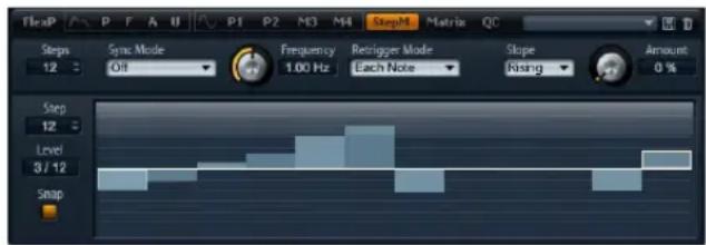
To access the Step Modulator:
- Go to the Edit page and select the synth or sample layer you want to adjust.
- In the upper section of the editor, click the StepMod page button.
Step Modulator presets
To the upper right of the lower section of the layer editor, you can load and save presets for the Step Modulator.
- To load a preset click on the preset loader and select the desired preset from the menu that pops up.
- To delete a preset from your system, click the trash bin button. Then you will be asked to confirm the deletion.
- To save a new preset, click the floppy disk button. A file dialog opens where you can name and save your preset file.
Editing steps
You can adjust the steps by using the mouse:
- To set the level of a step, click at the desired position in the graphical editor.
- To set the exact value you wish, drag the step up and down like a fader.
- To reset a step to a level of 0%, [Ctrl]-click the step.
- To reset all steps, [Shift]+[Ctrl]-click in the graphical editor.
- To adjust all steps at once, [Shift]-drag a step.
- To draw a ramp with steps, [Alt]-click and draw a line.
- To draw symmetric ramps, [Shift] + [Alt]-click and draw a line.
You can adjust the steps by using the computer keyboard:
- Use the Step text field, to select a certain step.
- To set the level of the selected step, enter the desired value in the level text field.
- To increment or decrement the selected step, use the up and down arrow keys respectively.
By default, the increment or decrement is in steps of 1%. Hold [Shift] to increment or decrement the selected step in steps of 1/10th %. - While the graphical editor has the keyboard focus, you can use the left and right arrow keys to select the previous or next step.
Steps
Here you set the number of steps the sequence plays. The control range is from 2 to 32 steps.
Sync mode
By setting a note value, you can synchronize the steps to the tempo of the host application. Alternatively, you can specify a frequency at which the sequence repeats. If you can set a note value or a frequency depends on the option you select here:
Option Description
Off Select this to adjust the speed at which the sequence repeats in Hertz. Whether the sequence restarts or not when you play a note depends on the selected Retrigger mode.
Tempo + Retrig Select this to adjust the length of the steps in fractions of beats, i.e. 1/4, 1/8, etc. The speed of the modulation depend on the number of steps, the note value and the tempo you set in your host application. By activating the T button, the note values become triplet note values. Whether the sequence restarts or not when you play a note depends on the selected Retrigger mode.
Tempo + Beat Select this to adjust the length of the steps i n fractions of beats, i.e. 1/4, 1/8, etc. The speed of the modulation depend on the number of steps, the note value and the tempo you set in your host application. By activating the T button the note values become triplet note values. The sequence restarts with the transport of the host and lines up to the beats of the song. The Retrigger setting does not come into effect.
Frequency
When Sync mode is set to "Off", this controls the speed at which the sequence repeats. The control range is from 0.01 Hz to 30 Hz.
Note
When Sync mode is set to one of the tempo settings, this adjusts the length of the steps in fractions of beats. The following note values can be set: 1/256, 1/256T, 1/128, 1/128T, 1/64, 1/64T, 1/32, 1/32T, 1/16, 1/16T, 1/8, 1/8T, 1/4, 1/4T, 1/2, 1/2T and 1.
Triplets
By activating the T button, the note values you set with Note become triplets.
Retrigger mode
Here you can determine whether the sequence restarts or not when you play a note. The Retrigger mode is only available when Sync mode is set to "Off" or "Tempo + Retrig".
Option Description
Off The sequence is not restarted. Instead, it resumes play-back at the last position when you released the key.
First Note The sequence restarts when a note is triggered and no other notes are already held.
Each Note The sequence restarts each time a note is triggered.
Slope
Depending on the setting you select here, the Step Modulator jumps from step to step or ramps between the steps. You can define a slope for rising, falling or all edges of the steps. The setting "None" produces hard steps. Use Slope Amount to set the time it takes to ramp from one step to the other.
Option Description
None Hard Steps.
Rising Only rising edges are ramped.
Falling Only falling edges are ramped.
All All edges are ramped.
Slope Amount
When Slope is set to "Rising", "Falling" or "All", this determines the time it takes to ramp from one step to the other. The control range is from 0% to 100%. The higher the setting, the smoother the transitions between steps.
Step
Use this to select a certain step. The control range is from step 1 to 32. The level text field updates accordingly.
Level
This shows the level of the currently selected step. The control range is from -100% to +100%.
To adjust the level in quantized steps of 1/12th, activate Snap.
Snap
When Snap is activated, the level of each step can only be adjusted in quantized steps of 1/12th. The control range is from -12/12 to 12/12. This feature, for example, can be used to produce modulations in steps of semitones.
Producing modulations in steps of semitones
To produce modulations in steps of semitones:
- Activate Snap on the Step Modulator.
- In the Modulation Matrix, assign the Step Modulator to Pitch.
- Set Depth to +12.
Now, the levels of the steps represent intervals in semitones. - Finally, go back to the Step Modulator and adjust each step to the desired interval.
Mod Matrix page
The Mod Matrix page of synth and sample layers gives you access to additional modulations of the layer. The concept of controlling one parameter by another is called modulation. HALion Sonic offers many fixed assigned modulations such as the amplitude and filter envelopes, or pitch key follow.
To assign additional modulations, use the Modulation Matrix. Assigning modulations means to interconnect modulation sources such as LFOs and envelopes, with modulation destinations like Pitch, Cutoff, Amplitude, etc. The Modulation Matrix offers you up to 32 freely assignable modulations, each with a source, a modifier and a destination with adjustable depth. All modulation sources and destinations can be assigned multiple times. The polarity of each source can be switched between unipolar and bipolar behavior. A selectable modifier and user-definable curves and ranges give you further control over the modulation.
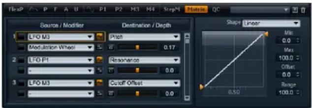
To access the Modulation Matrix:
- Go to the Edit page and select the synth or sample layer you want to adjust.
- In the lower section of the editor, click the Matrix page button.
The Modulation Matrix is divided into two sections separated by the vertical scroll bar. The section to the left displays the Modulation Rows. Here, you can assign modulation sources to destinations and adjust the modulation depth. In the section to the right, you find settings for the Curve and Range editor to make further adjustments for the currently selected modulation source.
Using the Modulation Rows
The Modulation Rows allow you to interconnect modulation sources with modulation destinations and to adjust the modulation depth.
- The parameters for setting up a modulation can be accessed via 32 rows. Each row identifies by a number which is displayed to the left of the row. Use the scroll bar in the middle to access rows that are currently not visible.
- You can select modulation sources by using the Source drop-down menu at the upper left of each row.
- The Modifier drop-down menu to the lower left of each row allows you to select a second modulation source that controls the intensity of the first source or a modifier that alters the modulation signal of the first source.
- To switch the polarity of a source between unipolar and bipolar behavior, click the button to the right of the respective source. Modifiers do not have a polarity. Therefore, the polarity option is hidden when you select a modifier.
- Additional parameters of the selected modifier are displayed in the section to the right. Use the controls to adjust the modifier. To adjust the settings of a different modifier, click the button to the left of the modifier you want to edit.
-
To select the modulation destination, use the dropdown menu to the right of a row.
-
Use the horizontal fader below the destination to adjust the modulation depth. Usually, the modulation depth adjusts in percent (-100% to +100%). If you select Pitch as modulation destination, the modulation depth adjusts in semitones (-60 to +60 semitones).
- Click the bypass button in front of the depth control to switch the modulation temporarily off.
Unipolar vs. bipolar sources
The polarity of a modulation source specifies the value range it produces.
- Unipolar sources produce positive values only. The sources modulate between 0 and +1.
- Bipolar sources produce negative and positive values. The sources modulate between -1 and +1.
By default, some sources are unipolar and others are bipolar. However, you can change the polarity of a modulation source any time you want.
- To change the polarity of a source, click the button to the right of the respective source.
Using the Curve and Range editor
You can set up a curve and range per modulation source.
- The Curve and Range editor displays the settings of the currently selected source marked by an orange frame in the according Modulation Row. To adjust the settings of a different source, click the button to the left of the source you want to edit.
- The Curve editor allows you to change the characteristic of a modulation. The displayed curve is superimposed on the modulation source.
This way, you can change the modulation, for example, from linear to exponential or logarithmic behavior.
- By setting the minimum and maximum values, the modulation stays within the specified range only. In addition, you can specify an Offset and a Range for the modulation. For example, with an Offset and Range of +50% only the second half of the displayed curve will be superimposed on the modulation.
- The Curve editor offers different presets which you can select from the drop-down menu above the curve. To setup your own curve, select the Custom preset from the drop-down menu.
- You can edit the curve graphically with the mouse when the Custom preset is selected: Double-click in the editor to insert a new node. Double-click on a node to delete it. Drag the nodes to the desired positions to adjust the basic shape of the curve. Drag the lines between the nodes up or down to change the curvature.
Setting up a modulation
To set up a modulation:
- Select the synth or sample layer you want to adjust.
- Go to the Modulation Matrix.
- In one of the Modulation Rows, select a modulation source and destination, such as LFO1 as source and Pitch as destination.
- Use the horizontal fader below the destination to adjust the modulation depth.
- Play a few notes to hear the modulation.
- You can select a modifier or change the polarity of the source.
For example, from the modifier drop-down menu, select Pitch Bend as the second source and set its polarity to unipolar.
- Play a few notes to hear the modulation and use the Pitch Bend wheel from the example.
- Finally, use the Curve and Range editor to limit the modulation range or to adjust the characteristic of the modulation.
Modulation Sources
The modulation sources are available from the Source and Modifier drop-down menus. HALion Sonic offers you the following modulation sources:
Option Description
| LFO1 The first LFO of the layer which produces cyclic modulation signals. LFO1 is bipolar. | |
| LFO2 The second LFO of the layer which produces cyclic modulation signals. LFO2 is bipolar. | |
| Amp Env The Amp Envelope of the layer. The shape of the envelope equals the modulation signal. The Amp Env is unipolar. | |
| Filter Env The Filter Envelope of the layer. The shape of the envelope equals the modulation signal. The Filter Env is unipolar. | |
| Pitch Env The Pitch Envelope of the layer. The shape of the envelope equals the modulation signal. The Pitch Env is bipolar. | |
| User Env The User Envelope of the layer. The shape of the envelope equals the modulation signal. The User Env is bipolar. | |
| Step Mod The Step Modulator of the layer. This produces cyclic, rhythmically stepped modulation signals. The Step Modulator is bipolar. | |
| Glide The Glide signal of the source. Glide is unipolar. | |
| Key Exp This produces an exponential modulation signal derived from the MIDI note number. Exponential means this source works with destinations such as Pitch or Cutoff. Key Exp is bipolar. | |
| Key Lin This produces a linear modulation signal derived from the MIDI note number. Linear means a certain value will be added per octave, for example, 1000 Hz/Oct. Key Lin is unipolar. | |
| Note On Vel Note on velocity (how fast you hit a key) can be used as a modulation signal. Note On Vel is unipolar. | |
| Note On Vel Squared The squared version of the Note On Vel. Squared means you need to press the key harder to produce higher modulation values. | |
| Note Off Vel Note off velocity (how fast you released a key) can be used as a modulation signal. Note Off Vel is unipolar. While most of the MIDI keyboards cannot send note off velocity messages, your sequencer software will in most cases be able to produce such messages. | |
| Pitch Bend The position of the pitch bend wheel can be used as a modulation signal. Pitch Bend is bipolar. | |
| Mod Wheel The position of the modulation wheel can be used as a modulation signal. Mod Wheel is unipolar. |
Option Description
| Aftertouch Aftertouch (how hard you press a key down after you hit it) can be used as a modulation signal. Aftertouch is unipolar. Some MIDI keyboards cannot send aftertouch messages. However, your sequencer software will in most cases be able to produce such messages. | |
| MIDI Ctrl Any of the 120 available MIDI controllers can be used as a modulation signal. You can select the desired MIDI controller from the respective submenu. | |
| Quick Ctrl | One of the quick controls of the Program or layers that the Program contains can be used as a modulation signal. You can select the quick control from the respective submenu. Depending on the complexity of your Program, such as how much layers it has, the submenu lists more or less quick controls you can select. |
| Mod Module | Select this to assign monophonic modulation sources from MIDI Modules of the Program or layers. You can select the monophonic modulation source from the respective submenu. Depending on the complexity of your Program, the submenu lists more or less MIDI Modules you can select. If the Program contains no MIDI Modules at all, the submenu will be empty. |
| Noise Produces a random modulation signal. Noise is bipolar. | |
| Output | The audio output of the layer can be used as a modulation signal. Output is bipolar. |
| Bus 1-16 | Modulations that have been sent to one of the sixteen busses can be used as sources again. This way, you can combine several modulations to produce more complex signals. Select the according modulation bus to assign it as source. |
Modulation Destinations
Depending on the selected type of layer, the available modulation destinations varies. HALion Sonic offers you the following modulation destinations:
Option Description
| Pitch Modulates the pitch of the layer. For example, assign one of the LFOs to create a vibrato effect. When Pitch is selected, the modulation depth adjusts in semitones (-60 to +60). | |
| Cutoff | Modulates the filter cutoff of the layer. For example, assign the Step Modulator to create rhythmic patterns in the spectral timbre. |
| Resonance Modulates the filter resonance of the layer. Resonance changes the character of the filter. For example, assign velocity to resonance to accent the filter the harder you hit a note. | |
| Pan Modulates the position of the layer in the panorama. For example, assign the User Envelope to move the layer freely around. | |
| Level | This modulation adds to the level setting of the layer. It is ideal for effects such as tremolo. |
| Gain 1 | Gain 1 modulates the volume of the layer. The gain modulation multiplies with the volume of the layer. It is ideal for cross-fades between layers. |
| Gain 2 Basically the same as Gain 1. Gain 1 and 2 are multiplied with each other. This way, you can build more complex modulations. For example, use Gain 1 for cross-fading between layers and Gain 2 for fading them in or out. | |
| LFO1 Freq | Modulates the speed of LFO1. For example, assign After-touch to control the speed of a vibrato effect while you play. |
| LFO1 Shape Modulates the waveform of LFO1. For example, assign Key Exp to vary the waveform with the playing position on the keyboard. | |
| LFO2 Freq Same as LFO1 Freq, but for LFO2. | |
| LFO2 Shape Same as LFO1 Shape, but for LFO2. | |
| Step Mod Freq | Modulates the speed of the Step Modulator. For example, assign an LFO to increase or decrease the speed cyclically. |
| Step Mod Slope | Modulates the shape of the edges of the Step Modulator (the Slope parameter has to be active). For example, assign the modulation wheel to blend from hard to smooth edges. |
| Amp Env Attack | Modulates the time of the Amplitude Envelope Attack (the first segment of the envelope). The attack time cannot be modulated continuously. The time updates only when the segment starts. |
| Amp Env Decay | Modulates the time of the Amplitude Envelope Decay (all segments after the Attack and before the Sustain). The decay time cannot be modulated continuously. The time updates only when the segment starts. |
Option Description
| Amp Env Sustain | Modulates the level of the Amplitude Envelope Sustain. The sustain level cannot be modulated continuously. The level updates only when the segment starts. |
| Amp Env Release | Modulates the time of the Amplitude Envelope Release (all segments after the Sustain). The release time cannot be modulated continuously. The time updates only when the segment starts. |
| Filter Env Attack | Modulates the time of the Filter Envelope Attack (the first segment of the envelope). The attack time cannot be modulated continuously. The time updates only when the segment starts. |
| Filter Env Decay | Modulates the time of the Filter Envelope Decay (all segments after the Attack and before the Sustain). The decay time cannot be modulated continuously. The time updates only when the segment starts. |
| Filter Env Sustain | Modulates the level of the Filter Envelope Sustain. The sustain level cannot be modulated continuously. The level updates only when the segment starts. |
| Filter Env Release | Modulates the time of the Filter Envelope Release (all segments after the Sustain). The release time cannot be modulated continuously. The time updates only when the segment starts. |
| Pitch Env Attack | Modulates the time of the Pitch Envelope Attack (the first segment of the envelope). The attack time cannot be modulated continuously. The time updates only when the segment starts. |
| Pitch Env Decay | Modulates the time of the Pitch Envelope Decay (all segments after the Attack and before the Sustain). The decay time cannot be modulated continuously. The time updates only when the segment starts. |
| Pitch Env Sustain | Modulates the level of the Pitch Envelope Sustain. The sustain level cannot be modulated continuously. The level updates only when the segment starts. |
| Pitch Env Release | Modulates the time of the Pitch Envelope Release (all segments after the Sustain). The release time cannot be modulated continuously. The time updates only when the segment starts. |
| User Env Attack | Modulates the time of the User Envelope Attack (the first segment of the envelope). The attack time cannot be modulated continuously. The time updates only when the segment starts. |
| User Env Decay | Modulates the time of the User Envelope Decay (all segments after the Attack and before the Sustain). The decay time cannot be modulated continuously. The time updates only when the segment starts. |
| User Env Sustain | Modulates the level of the User Envelope Sustain. The sustain level cannot be modulated continuously. The level updates only when the segment starts. |
Option Description
| User Env Release | Modulates the time of the User Envelope Release (all segments after the Sustain). The release time cannot be modulated continuously. The time updates only when the segment starts. |
| Bus 1-16 | You can send any modulation to one of the sixteen bus-ses, for example, to produce more complex modulation signals. Select the bus you want to send the signals to as a destination. To use the modulation that was sent to a bus, assign the according bus as a modulation source. |
The following destinations are only available for synth layers:
Option Description
| Osc1 Pitch Modulates the pitch of oscillator 1. For example, assign one of the LFOs to detune the oscillator cyclically. |
| Osc1 Waveform Modulates the shape and character of oscillator 1. For example, assign one of the envelopes to change the character of the oscillator over time. |
| Osc1 Level Modulates the volume of oscillator 1. For example, assign the modulation wheel to fade the oscillator in and out while you play. |
| Osc2 Pitch Same as Osc1 Pitch, but for oscillator 2. |
| Osc2 Waveform Same as Osc1 Waveform, but for oscillator 2. |
| Osc2 Level Same as Osc1 Level, but for oscillator 2. |
| Osc3 Pitch Same as Osc1 Pitch, but for oscillator 3. |
| Osc3 Waveform Same as Osc1 Waveform, but for oscillator 3. |
| Osc3 Level Same as Osc1 Level, but for oscillator 3. |
| Sub Osc Level Modulates the volume of the sub oscillator. For example, assign the modulation wheel to fade-in the oscillator while you play. |
| Ring Mod Level Modulates the volume of the ring modulation effect. For example, assign the modulation wheel to fade-in the ring modulation while you play. |
| Noise Gen Level Modulates the volume of the noise generator. For example, assign the modulation wheel to fade-in the noise generator while you play. |
Modulation Modifiers
The modulation modifiers are available from the Modifier drop-down menu. The additional parameters of modifiers are displayed in the section to the right. HALion Sonic offers you the following modifiers:
Sample & Hold
The Sample & Hold modifier takes a sample of the modulation source whenever it receives a trigger signal. It holds the sampled value until it gets a new trigger. This way, you can quantize a continuous modulation signal. The Sample & Hold offers different options you can select from the submenu:
Option Description
| Trigger on Note-On | Select this to trigger the Sample & Hold manually: Each time you hit a note, the Sample & Hold takes a sample. |
| Trigger on LFO1 | Select this for periodic triggering of the Sample & Hold: The Sample & Hold takes a sample each time the waveform of LFO1 exceeds the zero crossing in upward direction. |
| Trigger on LFO2 | Select this for periodic triggering of the Sample & Hold: The Sample & Hold takes a sample each time the waveform of LFO2 exceeds the zero crossing in upward direction. |
| Trigger on Modulation Wheel | Select this to trigger the Sample & Hold manually: The Sample & Hold takes a sample each time the modulation wheel crosses the mid. |
| Trigger on Sustain | Select this to trigger the Sample & Hold manually: Each time you press the Sustain Pedal, the Sample & Hold takes a sample. |
Mod Matrix presets
To the upper right, you can load and save presets for the Mod Matrix.
- To load a preset, click on the preset loader and select the desired preset from the menu that pops up.
- To delete a preset from your system, click the trash bin button. You will be asked to confirm the deletion.
- To save a new preset, click the floppy disk button. A file dialog opens where you can name and save your preset file.
Inserts page
HALion Sonic offers you up to four insert effects for each of the four layers and for the program itself. The insert effects you assign to a layer affect only that layer. The insert effects you assign to the program affect all four layers together. Typically, you assign effects like EQ or Distortion to the separate layers, but effects like Delay or Reverb to the whole program.
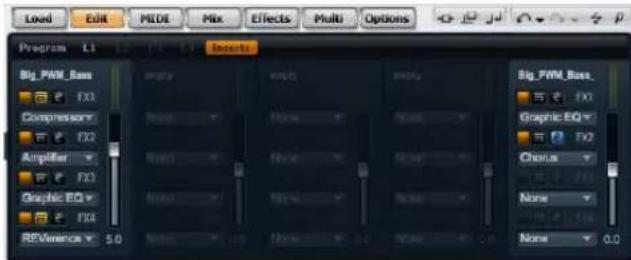
To access the Inserts page:
-
Go to the Edit page.
-
In the upper section of the editor, click the Inserts page button.
Using the insert slots
Each layer and the program has four slots for assigning insert effects. The handling is the same for all slots:
- To assign an insert effect, click the slot and select the desired effect from the menu.
- To remove an insert effect, click the slot and select "No Effect" from the menu. The effect with its current settings will be removed.
- The on/off button above the slot deactivates the effect without removing it. This way, you can switch the effect off without losing its settings. The effect is active, when the button is lit.
- The button next to the on/off button above the slot bypasses the effect. The bypass is active when the button is lit.
- To edit an insert effect, click the "e" button of the slot that holds the effect you want to edit. You can edit only one effect at a time. The "e" button stays lit to indicate which effect you edit. The parameters of the respective insert effect will be displayed in the lower section.
⇒ The Mix parameter of an effect inserted into an AUX bus is set to 50% by default.
Moving effects
To move effects from one slot to another on one bus, or from one bus to another:
- Drag the effect by its label (FX1, FX2, FX3, FX4) and move it over to the desired slot.
- An orange rectangle indicates where the effect will be inserted.
- Drop it to insert the effect and replace the currently loaded effect.
Effects can also be moved in between two effect slots to either insert them or to change their order:
- Drag the effect by its label (FX1, FX2, FX3, FX4) and move it close to the border of the two effects.
- An orange line indicates where the effect will be inserted.
- Drop it to place the effect in between the two adjacent effects.
Copying effects from one slot to another
To copy an effect from one slot to another:
- [Alt]-Drag the effect by its label (FX1, FX2, FX3, FX4) over the insert slot you want to copy it to.
- An orange rectangle indicates the slot where the effect will be inserted.
- Drop it to replace the current effect with a copy of the new effect.
Effect can also be moved in between two other effects:
- [Alt]-Drag the effect by its label (FX1, FX2, FX3, FX4) close to the border of the two effects.
- An orange line indicates where the effect will be inserted.
- Drop it to place a copy of the effect in between the two adjacent effects.
Adjusting the levels
To the right of the insert slots you find faders for adjusting the output levels of the program and layers.
To adjust the output level:
- Drag the fader of the program or layer you wish to adjust.
- Alternatively, enter a value in the text field below the fader.
⇒ By changing the levels here, levels in the respective parameters on the Program page will be reflected as well.
Instrument layer
For easy editing, instrument layers have fewer controls. In the list to the top left, you will see the Expressions the instrument layer contains. Typically, an Expression is a certain playing style of the instrument. In some cases, it can also be a part of the sound that can be turned on or off, for instance, to add realism or to maximize the performance. To the right and below, you will find the Pitch, Filter and Amplifier settings of the currently selected Expression.
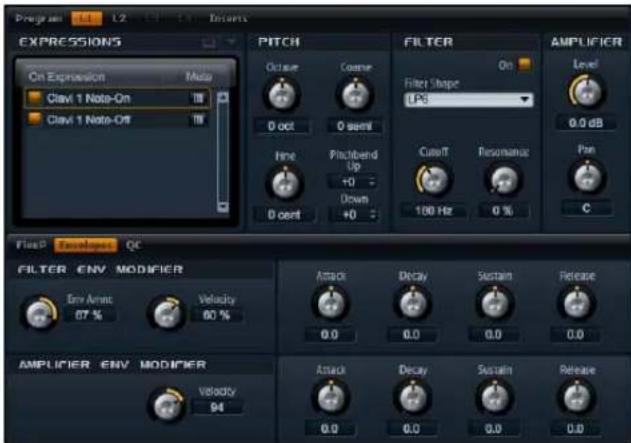
To load an Expression:
- Click the "On" switch to load an Expression. This option allows you to reduce the amount of RAM usage by turning off Expressions that are not need. You cannot switch to an Expression that has not been loaded before.
To edit an Expression:
- Select the Expression you want to edit in the list to the left.
- To the right and below, adjust the parameters as desired. Only the selected Expression will be modified.
To mute an Expression:
- Click the Mute button in the list to the left. The Expression will not play back while this is active.
- Click the button again to make the Expression audible again.
⇒ You can activate "Select Expression via MIDI" in the Expression list if you want the editor to follow incoming MIDI key switches or MIDI controller values.
Pitch
This section gives you access to the tuning of the Expression. With the Octave, Coarse and Fine parameters, you can adjust the tuning in steps of octaves, semitones and cents. In addition, you can also set the amount of pitch bend.
Octave
Here you can adjust the pitch in octave steps. The control range is from -5 to +5 octaves.
Coarse
Here you can adjust the pitch in semitone steps. The control range is from -12 to +12 semitones.
Fine
This parameter tunes the pitch in hundredths of a semi-tone (cents). The control range is from -100 to +100 cents.
Pitch Bend Up
Here you can set the range of the pitch modulation when moving the pitch bend wheel up. The control range is from -48 to +24 semitones.
Pitch Bend Down
Here you can set the range of the pitch modulation when moving the pitch bend wheel down. The control range is from -48 to +24 semitones.
Filter
The filter section offers settings to adjust the tone color of the Expression.
Filter On
Use this to activate the filter. Expressions without filter use less CPU cycles. Therefore, you should only activate this if your sound really needs a filter. The controls of the section turn dark when deactivated.
Filter shape
You can select from 23 different filter shapes. By selecting the filter shape you determine which frequencies will be affected. The letters and numbers indicate the filter shape: For example, LP12 is short for low-pass 12dB/oct.
You can select from the following filter shapes:
Filter shape Description
LP24 Low-pass filter with 24 dB/oct. Frequencies above the Cutoff will be attenuated.
LP18 Low-pass filter with 18 dB/oct. Frequencies above the Cutoff will be attenuated.
LP12 Low-pass filter with 12 dB/oct. Frequencies above the Cutoff will be attenuated.
LP6 Low-pass filter with 6 dB/oct. Frequencies above the Cutoff will be attenuated.
BP12 Band-pass filter with 12 dB/oct. Frequencies below and above the Cutoff will be attenuated.
BP24 Band-pass filter with 24 dB/oct. Frequencies below and above the Cutoff will be attenuated.
HP6+LP18 High-pass filter with 6 dB/oct. plus low-pass filter with 18 dB/oct. (asymmetric band-pass filter). Frequencies below and above the Cutoff will be attenuated. The frequencies above will fall off stronger.
HP6+LP12 High-pass filter with 6 dB/oct. plus low-pass filter with 12 dB/oct. (asymmetric band-pass filter). Frequencies below and above the Cutoff will be attenuated. The frequencies above will fall off stronger.
HP12+LP6 High-pass filter with 12 dB/oct. plu s low-pass filter with 6 dB/oct. (asymmetric band-pass filter). Frequencies below and above the Cutoff will be attenuated. The frequencies below will fall off stronger.
HP18+LP6 High-pass filter with 18 dB/oct. plu s low-pass filter with 6 dB/oct. (asymmetric band-pass filter). Frequencies below and above the Cutoff will be attenuated. The frequencies below will fall off stronger.
HP24 High-pass filter with 24 dB/oct. Frequencies below the Cutoff will be attenuated.
HP18 High-pass filter with 18 dB/oct. Frequencies below the Cutoff will be attenuated.
Filter shape Description
HP12 High-pass filter with 12 dB/oct. Frequencies below the Cutoff will be attenuated.
HP6 High-pass filter with 6 dB/oct. Frequencies below the Cutoff will be attenuated.
BR12 Band-reject filter with 12 dB/oct. Frequencies around the Cutoff will be attenuated.
BR24 Band-reject filter with 24 dB/oct. Frequencies around the Cutoff will be attenuated.
BR12+LP6 Band-reject filter with 12 dB/oct. plus low-pass filter with 6 dB/oct. Frequencies around and above the Cutoff will be attenuated.
BR12+LP12 Band-reject filter with 12 dB/oct. plus low-pass filter with 12 dB/oct. Frequencies around and above the Cutoff will be attenuated.
BP12+BR12 Band-pass filter with 12 dB/oct. plus band-reject filter with 12 dB/oct. Frequencies below, above and around the Cutoff will be attenuated.
HP6+BR12 High-pass filter with 6 dB/oct. plus band-reject filter with 12 dB/oct. Frequencies below and around the Cutoff will be attenuated.
HP12+BR12 High-pass filter with 12 dB/oct. plus band-reject filter with 12 dB/oct. Frequencies below and around the Cut-off will be attenuated.
AP All-pass filter with 18 dB/oct. Frequencies around the Cutoff will be attenuated.
AP+LP6 All-pass filter with 18 dB/oct. pl us low-pass filter with 6 dB/oct. Frequencies around and above the Cutoff will be attenuated.
HP6+AP High-pass filter with 6 dB/oct plus all-pass filter with 18 dB/oct. Frequencies around the Cutoff will be attenuated.
Cutoff
Here you can adjust the Cutoff frequency of the filter. The control range is from 20 Hz to 22.000 Hz. The effect depends on the filter type you have selected.
Resonance
This parameter emphasizes the frequencies around the cutoff. The control range is from 0% to 100%. For an electronic sound, increase the Resonance. At higher settings of Resonance the filter will self-oscillate, which delivers a ringing tone.
Filter Env Modifiers
This section offers parameters to modify the filter envelope of the Expression. You can offset the Attack, Decay, Sustain and Release of the filter envelope. In addition, you can also adjust the level velocity of the filter envelope.
Env Amnt
Env Amnt is short for Envelope Amount. Use this parameter to adjust the Cutoff modulation from the Filter Envelope. The control range is from -100% to +100%. Setting negative values inverts the direction of the modulation from the Filter Envelope.
Velocity
Use this parameter to adjust how velocity affects the level of the filter envelope. The level of the envelope depends on the setting of this parameter and how hard you hit a note: Positive values increase and negative values decrease the level of the envelope the harder you hit a note. The control range is from -200% to +200%.
Attack
Use this to offset the Attack time of the filter envelope. The control range is from -100% to +100%. Positive values decrease and negative values increase the Attack time.
Decay
Use this to offset the Decay time of the filter envelope. The control range is from -100% to +100%. Positive values decrease and negative values increase the Decay time.
Sustain
Use this to offset the Sustain level of the filter envelope. The control range is from -100% to +100%. Positive values increase and negative values decrease the Sustain level.
Release
Use this to offset the Release time of the filter envelope. The control range is from -100% to +100%. Positive values decrease and negative values increase the Release time.
Amplifier
The Amplifier section gives you access to the level and pan settings of the Expression. With level you adjust the loudness of the Expression. With pan you specify the position of the Expression in the stereo panorama.
Level
Here you can you can adjust the loudness of the layer. The control range is from -∞ dB to +12 dB.
Pan
Here you can set the position of a sound in the stereo panorama. The control range is from hard left (-100%) to hard right (+100%).
Amplifier Env Modifiers
This section offers parameters to modify the amplifier envelope of the Expression. You can offset the Attack, Decay, Sustain and Release of the amplifier envelope. In addition, you can also adjust the level velocity of the amplifier envelope.
Velocity
Use this parameter to adjust how velocity affects the level of the amplifier envelope. The level of the envelope depends on the setting of this parameter and how hard you hit a note: Positive values increase and negative values decrease the level of the envelope the harder you hit a note. The control range is from -200% to +200%.
Attack
Use this to offset the Attack time of the amplifier envelope. The control range is from -100% to +100%. Positive values decrease and negative values increase the Attack time.
Decay
Use this to offset the Decay time of the amplifier envelope. The control range is from -100% to +100%. Positive values decrease and negative values increase the Decay time.
Sustain
Use this to offset the Sustain level of the amplifier envelope. The control range is from -100% to +100%. Positive values increase and negative values decrease the Sustain level.
Release
Use this to offset the Release time of the amplifier envelope. The control range is from -100% to +100%. Positive values decrease and negative values increase the Release time.
Expression Maps
Using Expression Maps
For more realistic performances, many instrument layers use key switches to switch between different Expressions, i.e. different articulations and playing styles of the same instrument. These key switches are set to rather low keys to maximize the playable range and they cannot be changed internally to ensure that performances played by Flex-Phrasers always sound the same - FlexPhrasers expect the key switches of certain Expressions on a specific MIDI note.
However, in some cases, you need to shift the key switches into the playable keyboard range to get access to them. In other cases, you might want to select the Expression using a MIDI controller. In both cases, you can use so-called Expression Maps to customize the internal setting for your own needs.
Selecting the Expressions
You can select which of the listed Expressions you want to use in your Expression Map. Expressions you do not activate will not be included in your Expression Map.
To activate or deactivate an Expression:
- Click the button to the left of the name of the Expression.
- Deactivated Expressions turn dark.
⇒ Some instruments layers consist of multiple Expressions that are not switchable via a key switch. For example, instrument noises typically do not have a key switch assigned. In this case, you can still select the individual Expressions and edit them, however, you cannot apply any key switch functionality. The key switch option menu is therefore disabled.
Setting the mode
To define whether you want to use only the internal key switches, to remap them to other keys or to use a MIDI controller instead, open the options menu on the Expression list:
- Go to the Edit page and select the layer you want to adjust.
- Click the menu triangle on top of the Expression list.
- Select the desired mode.
Mode Description
| Key Switch Only the internal key switche an Expression. | s can be used to switch to |
Remapped The original key switches can be remapped to different keys.
MIDI Controller A MIDI controller can be used to remotely switch between the internal key switches.
⇒ No matter which condition you select, the internal key switch assignments still work in parallel. This is mostly important for FlexPhrases that make use of the key switches. The last key switch that is received always has priority.
Key Switch mode
The Key Switch mode uses the internal key switch assignments. The key switches are displayed in the list.
Remapped mode
The Remapped mode allows you to transpose the fixed, internal key switch assignments into the playable range of your MIDI keyboard. Each Expression displays the MIDI note of the internal key switch and a MIDI note for re-assigning the key switch next to its name. The MIDI note of the internal key switch is for indication only and cannot be edited.
To transpose the internal key switches:
- Set the mode to Key Switch.
- Enter the MIDI note you want the expression to be re-assigned to.
⇒ The MIDI notes you use for key switches do not trigger samples anymore. They trigger the internal key switch instead. Therefore, you cannot use them for normal playing anymore.
MIDI Controller mode
The MIDI Controller mode allows you to define a MIDI controller that remotely switches between the internal key switches. The defined MIDI controller switches only between the active expressions.
To assign a MIDI controller:
- Set the mode to MIDI Controller.
- Open the menu again and select "Lear CC".
- Turn on the desired Hardware controller.
FlexPhraser
Each program features up to five arpeggio and phrase players so-called FlexPhrasers. There is one FlexPhraser for each layer and one for the program. While the program FlexPhrasers always work with phrases, the layer Flex-Phrasers functionality changes with the layer type.
- For synth, sample, instrument or drum layers, a Flex-Phraser can playback anything from basic synth arpeggios over dynamic drum phrases to realistic accompaniment phrases for guitar, bass, piano, etc. You can select from over 1400 phrases that suit a wide range of musical instruments and styles. Depending on the selected phrase, the FlexPhraser uses your live playing to modify the phrase in real-time. This allows you, for instance, to increase the complexity of a drum pattern by playing one to four keys, or to re-harmonize phrases by playing different chords.
- In the case of loop layers, the FlexPhraser triggers the slices of the loop with their original timing and order. You can trigger a transposed version of the loop, playing higher or lower in pitch. In addition, you can vary the order with a random function and export the slice sequence to your host sequencer via drag and drop.
When working with loops you can play the individual slices and the entire loop. For this purpose the key range is divided into two halves. The lower half triggers the loop; the upper half can be used to play single slices. This different functionality is indicated by keys shaded in green for the loop keys and normal black/white keys for the Slices. Keys that do not trigger anything appear in grey.
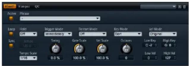
FlexPhraser page
To edit the program FlexPhraser:
- Go to the Edit page.
- From the upper of the Edit page, select program.
- Go to the lower section of the Edit page and click the FlexP button.
- Depending on the type of layer, the look and parameter set of the FlexPhraser varies slightly.
To edit a layer FlexPhraser:
- Go to the Edit page.
- From the upper of the Edit page, select the desired layer (L1, L2, L3 or L4).
- Go to the lower section of the Edit page and click the FlexP button.
- Depending on the type of layer, instrument or loop, the look and parameter set of the FlexPhraser varies slightly.
FlexPhraser presets
To the upper right, you can load and save presets for the FlexPhraser. In addition to the selected phrase, these presets also contain the performance settings of the Flex-Phraser, such as Tempo, Tempo Scale, Loop, Swing, etc.
- To load a preset, click on the preset loader and select the desired preset from the menu that pops up.
-
To delete a preset from your system, click the trash bin button. You will be asked to confirm the deletion.
-
To save a new preset, click the floppy disk button. A file dialog opens where you can name and save your preset file.
⇒ Presets can only be saved and loaded for phrases not for sliced loops.
FlexPhraser with phrases
Programs as well as synth, sample, instrument or drum layers provide a FlexPhraser that comes with the following features:
Active
Click the Active button at the upper left to switch the phrase on and off.
Loading FlexPhrases
The FlexPhrases are sorted by the type of instrument in several subfolders. Each instrument subfolder contains phrases of different musical styles.
To load a phrase:
- Go to the top of the FlexPhraser and click the Phrase drop-down menu.
- Go to the submenu of the desired instrument.
- Select the FlexPhrase you wish to load.
In general, you can apply any phrase to any type of instrument. However, please keep in mind that a FlexPhrase for guitar might not sound as good when used with a piano and vice versa.
⇒ Some FlexPhrases make extensive use of key switches to switch between multiple playing styles of an instrument while playing. These phrases work best with the corresponding instrument layers. They can be found in the "Expression" subfolder of the phrases menu.
Loop
This option defines whether the phrase is played once or continuously in a loop. When activated, the phrase plays in a loop.
Hold
With Hold you can prevent the phrase to stop or change when the keys are released. In addition, the Gated mode plays silently in the background when you release the keys, and resumes playback at the current position when you press the keys again.
You can select one of the following options:
Option Description
Off The phrase changes immediately when releasing a key. The phrase stops immediately when releasing all keys.
On The phrase plays to end even when the keys are re- leased. When the Loop option is activated, the phrase plays continuously in a cycle.
Gated The phrase starts playback with the first key being played. It plays silently in the background even when the keys are released, and resume playback at the current position when you press any of the keys again. This way, you can gate the playback of the phrase.
Trigger mode
The Trigger mode defines when the FlexPhraser scans for new keys you play on the keyboard.
You can select one of the following options:
Option Description
Immediately The FlexPhraser scans for new keys all the time. The phrase changes accordingly to your playing immediately.
Next Beat The FlexPhraser scans for new keys upon new beats. The phrase changes accordingly to your playing on each new beat.
Next Measure The FlexPhraser scans for new keys upon new measures. The phrase changes accordingly to your playing on each new measure.
Restart mode
Depending on the selected Restart mode and your playing, you can restart the playback from the beginning of the phrase.
You can select one of the following options:
Option Description
Off The phrase runs continuously and will not restart upon chord or note changes.
New Chord Select this to restart the phrase on new chords. However, the phrase will not restart upon legato played notes, for example, if you play additional notes to a chord you are holding already.
| Option | Description |
| New Note | Select this to restart the phrase with each new note you play. Here, the phrase will restart also upon legato played notes. |
| Sync to Host | Select this to align the phrases with the beats and measures of your host application. The phrase aligns to the beats and measures each time you start the transport. |
Key mode
This option defines if the order of the notes, as you played them chronically on the keyboard, affects the playback of the phrase.
You can select one of the following options:
Option Description
Sort The notes play in the order of the selected pattern. The chronological order does not have an influence.
As Played The notes play in the chronological order as you played them on the keyboard.
Direct The phrase itself does not output any note events. Instead, it outputs controller events only. You hear the notes you play plus any controller events of the phrase, such as pitch bend, volume, pan, etc. Not all phrases contain controller data. Please consult the documentation of the phrase to see if it does.
Vel mode
This option specifies if the velocity of the notes you play affects the notes of the phrase or not.
You can select one of the following options:
Option Description
Original The notes of the phrase play with the velocity as specified by the original sequence data of the phrase.
As Played The notes of the phrase play with the velocity you are playing on the keyboard.
Original + As The velocity of the sequence data of the phrase is scaled by the velocity you are playing on the keyboard.
Sync
To synchronize the phrase to the tempo of your host application, activate Sync. The Tempo control is disabled when Sync is activated.
In addition, you can set the Restart mode to "Sync to Host" (see below for details). This aligns the phrase with the beats and measures of your host application.
Tempo
When Sync is deactivated, use the Tempo control to set the internal playback speed of the FlexPhraser. The playback speed of the phrase is specified in Beats per Minute (BPM). In addition, Tempo Scale gives you further control over the playback speed. The Tempo control is inactive when Sync is activated.
Tempo Scale
This parameter defines the rate at which notes will be triggered, in other words, the speed at which the phrase is running. A value of 1/16 corresponds to the original speed as specified under Tempo. Setting the value, for example, to 1/8 cuts the speed to half. Setting it to 1/32 doubles it. Other values increase or decrease the speed accordingly.
The control range is 1/64, 1/32, 1/32D, 1/16, 1/16T, 1/16D, 1/8, 1/8T, 1/8D, 1/4, 1/4T, 1/4D, 1/2, 1/2T, 1/2D, 1/1T, 3/4 and 4/4.
Swing
Use this parameter to shift the timing of notes on even numbered beats. This way, the phrase gets a swing feeling. The control range is from -100% to +100%. Negative values shift the timing backward, and the notes will be played earlier. Positive values shift the timing forward, and the notes will be played later.
Gate Scale
This parameter allows you to shorten or lengthen the notes of the phrase. At a value of 100% the notes play with their original gate length.
Vel Scale
This parameter allows you to raise or lower the note on velocities of the phrase. At a value of 100% the notes will be played with their original velocity.
Octaves
This setting extends the phrase playback to higher or lower octaves. The control range is from -3 to +3 octaves. Positive settings extend the playback to higher and negative settings to lower octaves. For example, a value of +1 first plays the phrase in the octave range you originally played. Then, it repeats the phrase one octave higher.
Play Range
You can use the Play Range parameters to determine which keys and velocities trigger the phrase playback.
Low Key
This defines the lowest key on which the phrase is triggered. The range extends from C-2 to G8.
High Key
This defines the highest key on which the phrase is triggered. The range extends from C-2 to G8.
Low Vel
This defines the lowest velocity on which the phrase is triggered. The range extends from 0 to 127.
High Vel
This defines the highest velocity on which the phrase is triggered. The range extends from 0 to 127.
FlexPhraser for loop layers
When using loop layers, the FlexPhraser offers the following features:
Loop
This option defines whether the loop sequence is played once or continuously in cycles. When activated, the loop sequence plays in cycles.
Hold
With Hold you can prevent the loop to stop or change when the keys are released. In addition, the Gated mode plays silently in the background when you release the keys, and resumes playback at the current position when you press the keys again.
You can select one of the following options:
Option Description
Off The loop stops immediately when releasing a key.
On The loop plays to end even when the keys are released. When the Loop option is activated, the loop plays continuously in cycles.
Gated The loop starts playback with the fi rst key being played. It plays silently in the background even when the keys are released, and resume playback at the current position when you press any of the keys again. This way, you can gate the playback of the loop.
Trigger mode
The Trigger mode defines when the FlexPhraser scans for new keys you play on the keyboard.
You can select one of the following options:
Option Description
Immediately The FlexPhraser scans for new keys all the time. The loop changes accordingly to your playing immediately.
Next Beat The FlexPhraser scans for new keys upon new beats. The loop changes accordingly to your play on each new beat.
Next Measure The FlexPhraser scans for new keys upon new measures. The loop changes accordingly to your play on each new measure.
Restart mode
Depending on the selected Restart mode and your play, you can restart the playback from the beginning of the loop.
You can select one of the following options:
Option Description
Off The loop runs continuously and will changes.
not restart upon note
First Note The loop restarts when a note is triggered and no other notes are already held.
Each Note The loop restarts each time a note is triggered.
Sync to Host Select this to align the loop with the beats and measures of your host application. The loop aligns to the beats and measures each time you start the transport.
Sync
To synchronize the loop to the tempo of your host application, activate Sync. The Tempo control is disabled when Sync is activated.
In addition, you can set the Restart mode to "Sync to Host" (see below for details). This aligns the loop with the beats and measures of your host application.
Tempo
When Sync is deactivated, use the Tempo control to set the internal playback speed of the loop. The playback speed of the loop is specified in Beats per Minute (BPM). In addition, Tempo Scale gives you further control over the playback speed. The Tempo control is inactive when Sync is activated.
Tempo Scale
This parameter defines the rate at which notes will be triggered, in other words, the speed at which the loop is running. A value of 1/16 corresponds to the original speed as specified under Tempo. Setting the value, for example, to 1/8 cuts the speed to half. Setting it to 1/32 doubles it. Other values increase or decrease the speed accordingly. The control range is 1/64, 1/32, 1/32T, 1/16T, 1/16, 1/8T, 1/16D, 1/8, 1/4T, 1/4, 1/2T, 1/4D, 1/2, 1/1T, 1/2D, 3/4 and 4/4.
Swing
Use this parameter to shift the timing of notes on even numbered beats. This way, the loop gets a swing feeling. The control range is from -100% to +100%. Negative values shift the timing backward and the notes will be played earlier. Positive values shift the timing forward and the notes will be played later.
Start
This allows you to shift the start of the loop in steps of 1/4 notes. The length of the loop is shortened accordingly.
Length
This parameter allows you to shorten the length of the loop in steps of 1/4 notes.
⇒ The control range of Start and Length varies with the original length of the loop.
Gate Scale
This parameter allows you to shorten the notes that play-back the slices. The control range is from 0% to 100%. At a value of 100% the slices play with their original gate length.
Quantize Note Value
This allows you to setup a quantization grid. You can force the timing of the slices to playback only at the note value you select here. You can set the note value to 1/64, 1/32, 1/32 T, 1/16 T, 1/16, 1/8 T, 1/16 D, 1/8, 1/4 T, 1/4, 1/2T, 1/4 D, 1/2, 1/1 T, 1/2 D, 1/1.
Quantize Amount
This parameter defines how much of the quantization grid is applied. A value of 100% means the slices playback only at the Quantize Note Value you specified. Smaller values move the notes only partially towards the next Quantize Note Value. With a value of 0% no quantization is applied at all.
Key Follow
Here you can adjust the pitch modulation from note number. The range is from -200% to +200%. Set this parameter to positive values to raise the pitch with notes above the Center Key. Use negative values to lower the pitch with notes above the Center Key. At +100% the pitch follows exactly the played note.
⇒ The Key Follow is limited to the keys that trigger the entire loop. It does not affect the keys that play the single slices.
Center Key
This parameter sets the note around where the Key Follow pivots. It ranges from C-2 to G8.
Random
To shuffle the playing order of the slices randomly, activate the Random button. To play the slices with their original order, deactivate the Random button.
⇒ The overall timing does not vary through this. Only the playing order of the slices varies through this, for example, slice 3 plays instead of slice 1, etc.
Depth
Here you adjust how much the playing order of the slices will be shuffled. Lower this value to keep the playing order of slices on the main beats. Raise this value to vary the playing order of slices on the main beats as well.
Trigger
Click this to shuffle the playing order again. Please note that the Pattern number changes with this.
Pattern
To predictably recall a certain random pattern, you can enter the Pattern number. If you recall a loop with a certain Depth and Pattern, it always sounds the same.
Exporting the loop sequence
The FlexPhraser of loop layers allows you to export the loop sequence as a MIDI part for your host sequencer.
To export the loop sequence:
- Drag the icon that looks like a MIDI socket to the project window of you host sequencer.
- Drop the MIDI part on an existing MIDI Track or on an empty space, which creates a new MIDI Track.
- Assign the MIDI Track to the respective slot in HALion Sonic.
FlexPhraser Phrases
Phrase playback types
HALion Sonic features a huge amount of phrase types organized in categorized folders such as Classic Arp, Synth Seq, Chord Seq, Bass and so on. Each folder can contain several category subfolders representing functional descriptions or musical styles.
The "Expression" folder contains phrases especially made for HALion Sonic's instrument layers. These phrases use key switches to switch between different playing styles to increase the realism of your performance.
The phrases that can be found in the various other categories use a number of different playback types to allow phrase specific user interaction while playing.
These phrases use one of the following playback types.
Option Description
Playback of a drum pattern Pressing any note(s) triggers the same rhythm pattern.
Playback only of The phrase is played back using only the played note and the played notes its octave notes.
Playback of a programmed sequence according to the played chord Pressing only one note, the phrase is played back using the programmed sequence — which means that notes other than the ones you play are triggered. Adding notes to those already held, changes the sequence accordingly — for example, the phrase plays back according to the chord you play.
Drum and loop layers
Drum and loop layers share the same set of controls. In the Key Map to the lower of the editor, you see the drum instruments or loop slices the layer contains, and how they map across the keyboard. In the upper section, you find the Pitch, Filter, Amplifier and Output settings of the currently selected drum instrument or loop slice. The lower section also gives you access to the FlexPhraser, the monophonic LFO and the layer quick control editor.
Using the Key Map
The Key Map indicates how the drum instruments or loop slices map across the keyboard.
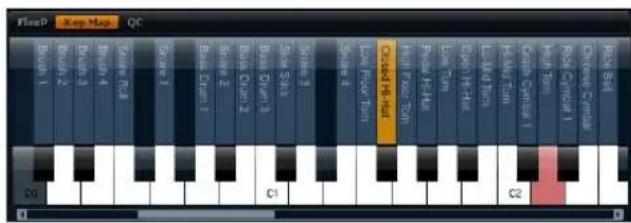
To access the Key Map:
- Go to the Edit page and select the drum or loop layer you want to adjust.
- Go to the lower of the drum or loop editor and click the Key Map page button.
When using the Key Map, the following applies:
- Keys with a drum instrument or loop slice assigned display in normal white and black.
-
The names of the drum instruments or loop slices display vertically above the keys.
-
Keys with nothing assigned are disabled and are displayed in grey.
- In case of a loop layer, the pitched part of the keyboard is displayed in orange.
- Hidden parts of the keyboard can be accessed with the scroll bar to the lower of the keyboard.
- Clicking a key plays and selects the respective drum instrument or loop slice.
⇒ The Key Map is used for indication and selection only. The mapping of the drum instruments and loop slices cannot be changed.
Editing drum instruments or loop slices
To edit a drum instrument or loop slice, you must select it first. You can select drum instruments or loop slices with the Key Map or your MIDI keyboard.
Selecting with the Key Map
To select a drum instrument or loop slice with the Key Map:
- Go to the Edit page and select the drum or loop layer you want to adjust.
- Go to the lower of the drum or loop editor and open the Key Map.
- On the keyboard to the lower of the Key Map, click the key of the drum instrument or loop slice you want to adjust.
- The drum instrument or loop slice is selected and the parameters at the upper will be updated respectively.
Multi selection editing
To edit multiple drum instruments or slices at the same time, you can use the multi selection functionality of the Key Map:
- Select one Key, press [Shift] and then select a second key to select all keys in between.
- Press [Ctrl] and then click keys to add or remove them from the current selection.
- Press [Ctrl] and start dragging the mouse over the desired keys to do a lasso selection.
- Press Shift + Ctrl and then drag the mouse over the desired keys to add additional keys per lasso selection to the current selection.
As soon as you start selecting multiple slices or drum instruments, changes may occur on certain settings. In such cases, the changes are indicated on the respective controls. Combo boxes get a red tinted background, value fields display their values in red, switches turn red (or half red if the focused Slice/instrument is set to off) and knobs show a red corona indicating the range in which values are set. Changing a parameter sets all selected loop slices or drum instruments to the same value and the red indication for that control disappears.
Selecting with the MIDI keyboard
To select a drum instrument or loop slice with your MIDI keyboard:
- Go to the Edit page and select the drum or loop layer you want to adjust.
- In the title bar of the upper section, click the button to the right to activate "Select via MIDI". The function is activated when the button is lit.
- On your MIDI keyboard, press the key that plays the drum instrument or loop slice you want to adjust.
- The drum instrument or loop slice is selected and the parameters at the upper will be updated accordingly.
⇒ By default all parameter changes are only applied to the currently selected drum instrument or loop slice. Click the "Sel" button in the upper title bar to switch to the "All" mode if you want to apply changes to all drum instruments or loop slices. You can also play multiple keys at a time to create a multi selection.
Accessing Pitch, Filter and Amp parameters
To access the Pitch, Filter and Amp parameters of a drum instrument or loop slice:
- Go to the Edit page and select the drum or loop layer you want to adjust.
-
Go to the lower section, open the Key Map and select the drum instrument or loop slice you want to edit. Alternatively, use your MIDI keyboard to select the drum instrument or loop slice.
-
Go to the upper section, select Pitch, Filter or Amp and adjust the parameters as desired.
→ Only the currently selected drum instrument or loop slice will be edited.
Pitch
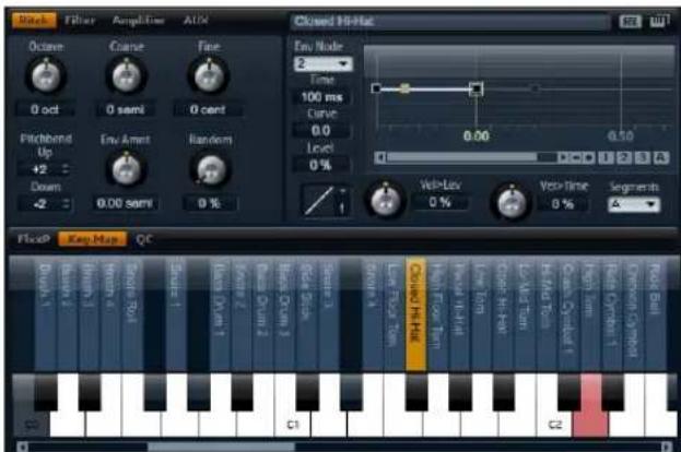
This section gives you access to the tuning of the drum instrument or loop slice. With the parameters Octave, Coarse and Fine, you can adjust the tuning in steps of octaves, semitones and cents. In addition, you can adjust the amount of pitch modulation from the Pitch envelope or randomly with each keystroke. Furthermore, you can set the pitch bend range for the up and down direction of the pitch bend wheel separately.
Octave
Here you can adjust the pitch in octave steps. The control range is from -5 to +5 octaves.
Coarse
Here you can adjust the pitch in semitone steps. The control range is from -12 to +12 semitones.
Fine
This parameter tunes the pitch in hundredths of a semi-tone (cents). The control range is from -100 to +100 cents.
Env Amnt
Env Amnt is short for Envelope Amount. This parameter determines how much the pitch is affected by the Pitch envelope. The control range is from -48.00 to +48.00 semitones.
Random
This parameter allows you to offset the pitch with each played note randomly. The strength of the randomization can be adjusted within a range from 0% to 100%. Higher values cause stronger variations. At a setting of 100% the random offsets can vary from -6 to +6 semitones.
Pitch Bend Up
Here you can set the range of the pitch modulation when moving the pitch bend wheel up. The control range is from -48 to +24 semitones.
Pitch Bend Down
Here you can set the range of the pitch modulation when moving the pitch bend wheel down. The control range is from -48 to +24 semitones.
Pitch Envelope
(See "Envelope pages" on page 34.)
Filter
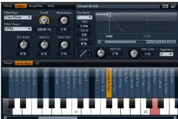
The filter section offers settings to adjust the tone color of the drum instrument or loop slice.
Filter type
By selecting the filter type you specify the basic sound character of the filter. HALion Sonic offers up to 23 filter shapes (for details on filter shapes, see below).
Filter shape
Filter type Description
| Off The filter section is switched off. Use this when no filter is needed for your sound and/or when you want to save CPU cycles. |
Classic This filter type offers 23 filter shapes with Resonance.
| Tube Drive This filter type offers a lot of character by adding warm, tube-like distortions. It comes with 23 filter shapes, adjustable Resonance and Distortion. |
You can select from 23 different filter shapes. By selecting the filter shape you determine which frequencies will be affected. The letters and numbers indicate the filter shape: For example, LP12 is short for low-pass 12dB/oct.
You can select from the following filter shapes:
Filter shape Description
| LP24 Low-pass filter with 24 dB/oct. Frequencies above the Cutoff will be attenuated. |
| LP18 Low-pass filter with 18 dB/oct. Frequencies above the Cutoff will be attenuated. |
| LP12 Low-pass filter with 12 dB/oct. Frequencies above the Cutoff will be attenuated. |
| LP6 Low-pass filter with 6 dB/oct. Frequencies above the Cutoff will be attenuated. |
| BP12 Band-pass filter with 12 dB/oct. Frequencies below and above the Cutoff will be attenuated. |
| BP24 Band-pass filter with 24 dB/oct. Frequencies below and above the Cutoff will be attenuated. |
| HP6+LP18 High-pass filter with 6 dB/oct. plus low-pass filter with 18 dB/oct. (asymmetric band-pass filter). Frequencies below and above the Cutoff will be attenuated. The frequencies above will fall off stronger. |
| HP6+LP12 High-pass filter with 6 dB/oct. plus low-pass filter with 12 dB/oct. (asymmetric band-pass filter). Frequencies below and above the Cutoff will be attenuated. The frequencies above will fall off stronger. |
| HP12+LP6 High-pass filter with 12 dB/oct. plu s low-pass filter with 6 dB/oct. (asymmetric band-pass filter). Frequencies below and above the Cutoff will be attenuated. The frequencies below will fall off stronger. |
| HP18+LP6 High-pass filter with 18 dB/oct. plu s low-pass filter with 6 dB/oct. (asymmetric band-pass filter). Frequencies below and above the Cutoff will be attenuated. The frequencies below will fall off stronger. |
Filter shape Description
| HP24 High-pass filter with 24 dB/oct. Frequencies below the Cutoff will be attenuated. |
| HP18 High-pass filter with 18 dB/oct. Frequencies below the Cutoff will be attenuated. |
| HP12 High-pass filter with 12 dB/oct. Frequencies below the Cutoff will be attenuated. |
| HP6 High-pass filter with 6 dB/oct. Frequencies below the Cutoff will be attenuated. |
| BR12 Band-reject filter with 12 dB/oct. Frequencies around the Cutoff will be attenuated. |
| BR24 Band-reject filter with 24 dB/oct. Frequencies around the Cutoff will be attenuated. |
| BR12+LP6 Band-reject filter with 12 dB/oct. plus low-pass filter with 6 dB/oct. Frequencies around and above the Cutoff will be attenuated. |
| BR12+LP12 Band-reject filter with 12 dB/oct. plus low-pass filter with 12 dB/oct. Frequencies around and above the Cutoff will be attenuated. |
| BP12+BR12 Band-pass filter with 12 dB/oct. plus band-reject filter with 12 dB/oct. Frequencies below, above and around the Cutoff will be attenuated. |
| HP6+BR12 High-pass filter with 6 dB/oct. plus band-reject filter with 12 dB/oct. Frequencies below and around the Cutoff will be attenuated. |
| HP12+BR12 High-pass filter with 12 dB/oct. plus band-reject filter with 12 dB/oct. Frequencies below and around the Cut-off will be attenuated. |
| AP | All-pass filter with 18 dB/oct. Frequencies around the Cutoff will be attenuated. |
| AP+LP6 | All-pass filter with 18 dB/oct. plus low-pass filter with 6 dB/oct. Frequencies around and above the Cutoff will be attenuated. |
| HP6+AP | High-pass filter with 6 dB/oct plus all-pass filter with 18 dB/oct. Frequencies around the Cutoff will be attenuated. |
Cutoff
Here you can adjust the Cutoff frequency of the filter. The control range is from 20 Hz to 22.000 Hz. The effect depends on the filter type you have selected.
Resonance
This parameter emphasizes the frequencies around the cutoff. The control range is from 0% to 100%. For an electronic sound, increase the Resonance. At higher settings of Resonance the filter will self-oscillate, which delivers a ringing tone.
Env Amnt
Env Amnt is short for Envelope Amount. Use this parameter to adjust the Cutoff modulation from the Filter Envelope. The control range is from -100% to +100%. Setting negative values inverts the direction of the modulation from the Filter Envelope.
Velocity
This parameter adjusts the Cutoff modulation from velocity. It ranges from -100% to +100%. Set this parameter to positive values to increase the Cutoff with higher velocities. Use negative values to decrease the Cutoff with higher velocities.
Distortion
This parameter adds a warm, tube-like filter distortion to the signal. The control range is from 0% to 100% . At higher settings, it allows a very intense distortion effect.
⇒ This parameter is only available for the Tube Drive filter type.
Filter Envelope
(See "Envelope pages" on page 34.)
Amplifier
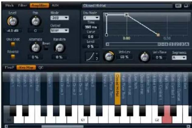
The Amplifier gives you access to the level and pan settings of the drum instrument or loop slice. In addition, you can activate One Shot and Reverse playback. With level you adjust the loudness of the sound. With pan you specify the position of the sound in the stereo panorama.
In addition, the pan position can be modulated with each keystroke randomly or left-right/right-left in alternation. Finally, you can select the output for each drum instrument or loop slice separately.
One Shot
Activate this to ignore any MIDI Note Off messages. The release segments of the envelopes will not be played while this is active. Instead, the envelopes play until the Sustain is reached and remain on that level as long as the sample plays back. Any loop settings of the sample will be ignored. For normal playback without ignoring MIDI Note Off messages, deactivate this. The release segments of the envelopes and any loop settings the sample might contain will be played back again. One Shot is active when the button is lit.
Reverse
Activate this to play the sample in reverse (from end to start). Any loop settings the sample may contain will be ignored while this is activated. For normal playback (from start to end), deactivate this. Reverse is active when the button is lit.
Level
Here you can you can adjust the loudness of the drum instrument or loop slice. The control range is from -∞ dB to +12 dB.
Pan
Here you can set the position of a sound in the stereo panorama. The control range is from hard left (-100%) to hard right (+100%).
Mode
With this option you can specify how the loudness changes across the stereo panorama. You can select between the four modes 0 dB, -3 dB, -6 dB and Off:
- The 0dB option works like a balance control: Setting the pan control towards the left fades out the right channel and vice versa. At the center position, the loudness is not cut.
- The -3dB option uses the cosine/sine pan law: The loudness is cut by -3dB at the center position, but the energy is preserved when moving the source signal across the stereo panorama. The -3dB option sounds more natural. The transition from hard left to hard right sounds much smoother than with the 0dB or the -6dB setting.
- The -6dB option uses the linear pan law: The loudness is cut by -6dB at the center position, and the energy is not preserved when moving the source signal across the stereo panorama. The -6dB option sounds more synthetic. The transition from hard left to hard right sounds more abrupt than with the -3dB setting.
- When set to "Off" no loudness correction is applied when a signal is panned across the stereo panorama.
Output
Here you can select the output for each drum instrument or loop slice separately. If you do not want the signal to be sent to the output that is specified for the layer, you can select the Main or one of the 16 individual plug-in outputs instead.
Random
This parameter allows you to offset the pan position with each played note randomly. The strength of the randomization can be adjusted within a range from 0% to 100%. Higher values cause stronger variations. At a setting of 100% the random offsets can vary from fully left to fully right.
Alternate
This parameter allows you to alternate the pan position each time you play a note. For example, a value of +100% means the first note plays hard right, the second note hard left, and so on. You can specify the pan position for the first time you hit a note with the algebraic sign: For negative values the initial pan position will be left and for positive values it will be right. With the value in percent you determine the deviation across the stereo panorama. The control range is from -100% to +100%.
Reset
The initial pan position is set once after HALion Sonic is loaded. Then HALion Sonic counts each note you played to determine the next pan position. To reset this counter, click the Reset button next to the Alternate control.
Amp Envelope
(See "Envelope pages" on page 34.)
AUX
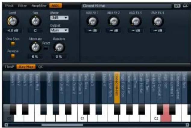
Each drum instrument and loop slice has individual send levels that feed the four global AUX FX busses. This allows you, for instance, to add more reverb to the snare drum and less effect to the bass drum.
AUX FX1 - 4
This adjusts the send levels for the four global AUX FX busses for each drum instrument or loop slice separately. The control range is from -∞ dB to 0 dB.
Envelopes
Each of the Pitch, Filter and Amp sections features a multi-segment envelope of its own. Each envelope has up to 128 nodes with the Time, Curve and Level parameters. The nodes and their parameters specify the overall shape of the envelope. You can edit one or multiple nodes by using the graphical envelope editor or by typing in values from keyboard. For a complete description on how to edit the envelope graphically please refer to the section "Envelope pages" on page 34.
Level Velocity
Use this parameter to adjust how velocity affects the level of the envelope. The level of the envelope depends on the setting of this parameter and how hard you hit a note:
Positive values increase and negative values decrease the level of the envelope the harder you hit a note. The control range is from -200% to +200%.
Level Velocity Curve
You can select one of eight curves to specify how the incoming velocity translates to the level of the envelope. The characteristic of each curve is displayed by a small icon.
The menu offers the following mathematical functions for velocity:
- 1 = Linear
- 2 = Squared
■ 3 = Squared Inverse - 4 = 2 Poles Squared
- 5 = 2 Poles Squared Inverse
- 6 = Cubic
- 7 = Quadric
- 8 = dB
- 9 = Logarithmic
- 10 = Constant (127)
Velocity to Time
Use this parameter to adjust the influence of velocity on the times of the envelope. Positive values decrease the times for higher velocity values. Negative values increase the times for higher velocity values. The amount ranges from -100% to +100%. In addition, with Segments you can select which stages of the envelope will be affected by this parameter.
Segments
From the pop-menu you can select which stages of the envelope will be affected by the Velocity to Time parameter.
- A: The velocity affects the attack time only.
-
A + D: The velocity affects all times until the sustain.
-
D: The velocity affects all times until the sustain but without the attack.
- A + R: The velocity affects the attack and the release times.
- All: The velocity affects all times.
Using the LFO of loop layers
In addition to the parameters described above, loop layers offer a monophonic LFO with adjustable Depth for Pitch, Cutoff and Pan.
To access the LFO of loop layers:
- Go to the Edit page and select the loop layer you want to adjust.
- Go to the lower of the loop editor and click the LFO page button.
When using the LFO of loop layers, the following applies:
- The modulation of Pitch, Cutoff and Pan goes to all slices simultaneously. The modulation depth cannot be set separately per slice.
- The filter must be activated to hear the modulation of the Cutoff.
- With a Resonance of 100% you might hear clicks because the slice ends abruptly, but the filter still produces a sound from self-oscillation. In such a case, go to the respective FlexPhraser and reduce the Gate Scale until the clicks are gone. In addition, you can adjust the amplifier envelope of the slices, for example, to increase the release of the envelopes.
LFO waveform and shape
Waveform selects the basic type of waveform and shape changes the characteristic of the waveform. The control range of shape is from 0% to 100%.
Option Description
| Sine | This produces a smooth modulation, suitable for vibrato or tremolo. Shape adds additional harmonics to the waveform. |
| Triangle | This is similar in character to Sine. The waveform periodically ramps up and down. Shape continuously changes the triangle waveform to a trapezoid. |
| Saw | This produces a “ramp” cycle. Shape continuously changes the waveform from ramp down to triangle to ramp up. |
Option Description
| Pulse This produces stepped modulation, where the modulation switches abruptly between two values. Shape continuously changes the ratio between the high and low state of the waveform. Set shape to 50% to produce a square wave. |
| Ramp This is similar to the Saw wave | form. Shape increasingly puts silence before the sawtooth ramps up. |
| Log Shape continuously changes the logarithmic curvature from negative to positive. |
| S & H 1 This produces random stepped modulation, where each step is different. Shape puts ramps between the steps and changes the S&H into a smooth random signal when fully turned right. |
| S & H 2 | This is similar to S & H 1. The steps are alternating between random high and low values. Shape puts ramps between the steps and changes the S & H into a smooth random signal when fully turned right. |
Frequency
This controls the frequency of the modulation, i.e. the “speed” of the LFO. The control range is from 0 Hz to 30 Hz. When Sync is activated, the frequency is set in fractions of beats.
Phase
This sets the initial phase of the waveform when the LFO is retriggered. The control range is from 0° to 360° .
Rnd
Rnd is short for Random. When activated, each note starts with a randomized start phase. The Phase control gets automatically disabled.
Sync
You can sync the LFO to the tempo of the host application. The behavior of the Frequency parameter changes with the option you select:
Option Description
| Off Select this to adjust the speed of the modulation in Hertz. | |
| Tempo + Retrig Select this to adjust the speed of the modulation in fractions of beats, i.e. 1/4, 1/8, etc. You can also set dotted and triplet note values. The restart behavior of the LFO depends on the Retrigger setting. | |
| Tempo + Beat Select this to adjust the speed of the modulation in fractions of beats, i.e. 1/4, 1/8, etc. You can also set dotted and triplet note values. The LFO restarts with the transport of the host and lines up to the beats of the song. The Retrigger setting does not come into effect. |
Retrigger
This defines whether or not the LFO is restarted when a note is triggered. The waveform restarts at the position you set with the Phase parameter.
Option Description
Off The LFO runs freely.
First Note The LFO restarts when a note is triggered and no other notes are already held.
Each Note The LFO restarts each time a note is triggered.
Pitch
This adjusts how much the LFO affects the Pitch of the slices. The control range is from -100% to +100%.
Cutoff
This adjusts how much the LFO affects the Cutoff of the slices. The control range is from -100% to +100%.
Pan
This adjusts how much the LFO affects the pan of the slices. The control range is from -100% to +100%.
Quick controls
The eight potentiometer controls, the horizontal and vertical axis of the sphere, and the modulation wheel located at the bottom of the plug-in surface can be assigned as quick controls. Quick controls allow you to remote control any parameter inside the program. Typically, they give you easy access to the most important sound parameters. There is a set of quick controls for the program. In addition, each layer has its own set of quick controls. The quick controls of the program allow you to control sound parameters across the four layers. The quick controls of the layers allow you to control sound parameters for each layer separately. You can switch between the quick controls of the program and the layers with the buttons at the left of the eight potentiometer controls.
You can assign the same quick control multiple times to different parameters. This allows you to do complex sound changes with a single control. To give you more control, each parameter assignment can be adjusted to a minimum and maximum range. In addition, you can select whether the quick control assignment behaves as either a continuous control or as a switch. A quick control remote controls a parameter either in Relative or Absolute mode. Relative mode changes the values of the assigned parameters without losing their relative settings. Absolute mode changes the assigned parameters by overwriting them with the value the quick control currently has. Mode selection can be made per assignment.
Quick controls 1-8

These are the eight potentiometer controls to the lower of the plug-in surface. Typically, the eight most important sound parameters will be assigned to them.
Sphere H and Sphere V
The Sphere is the orange, lucent ball to the lower right of the plug-in surface. The Sphere is a two-dimensional control, which means you can adjust two quick controls simultaneously by dragging the mouse horizontally and vertically within the lucent ball. The quick control on the horizontal axis is called Sphere H. The quick control on the vertical axis is called Sphere V. Typically, the Sphere has two parameters assigned that belong together. For instance, Cutoff is assigned to Sphere H and Resonance to Sphere V.
Center Horizontal/Center Vertical
You can setup the Sphere to return to its center position automatically. You can define the behavior for each axis separately.
To activate or deactivate Center Horizontal or Center Vertical:
-
Right-click (Win) or [Ctrl]-click (Mac) the Sphere.
-
In the menu, check or uncheck the options Center Horizontal or Center Vertical respectively.
Mod wheel
The modulation wheel is the wheel left to the preview keyboard of the plug-in. It is hardwired to MIDI controller #1 which is normally used as a source in the Modulation Matrix, but can be used as a quick control as well. Typically, you assign the Modulation Wheel to a parameter of an insert effect, such as the speed of the Rotary.
⇒ The fixed assignment of MIDI controller #1 cannot be changed. Therefore, the Modulation Wheel offers no "Learn CC" function.
Accessing quick controls
To access the quick controls of the program or one of its layers:
- Select the program you wish to edit in the Multi Program Rack.
- Go to the left of the quick controls and click the program button ("P") or one of the layer buttons ("L1" to "L4").
- The quick controls change to the settings of the program or the selected layer respectively.
⇒ The Sphere displays P, L1, L2, L3 or L4 to indicate the selected program or layer accordingly.
Assigning quick controls
When you assign quick controls in HALion Sonic, the following applies:
- The parameters of layers can only be assigned to the quick controls of the respective layer itself. For example, if the parameter belongs to layer 1, it can only be assigned to a quick control of layer 1. This includes the parameters in the program editor, the layer editor and the effect inserts of the respective layer.
- The parameters of layers cannot be assigned directly to quick controls of the program. First, you need to assign the parameter to a quick control of the layer. Then you can assign the quick control of the layer to a quick control of the program.
- The parameters of program effect inserts can be assigned directly to quick controls of the program.
To assign a quick control to a parameter:
- In the program or layer editor or the editor of an effect insert, right-click (Win) or [Ctrl]+click (Mac) the parameter you want to remote.
- From the menu, select the quick control you wish to assign, for example, quick control 1-8, sphere H & V, or mod wheel.
- The assignment is created.
⇒ The quick control range is automatically adapted depending on the current parameter value. This is to assure that the quick control provides optimal control range.
⇒ The parameters Polyphony, Low Key, High Key, Low Velocity, High Velocity and the Output cannot be assigned to quick controls.
⇒ You can also assign quick controls to the ADSR offsets of the envelopes by using the context menu on the graphical envelope controls.
To assign a quick control of a layer to the quick controls of the program:
- Select the respective layer from the left of the quick controls.
- Right-click (Win) or [Ctrl]+click (Mac) the quick control you want to remote.
- From the menu, select the program's quick control you wish to assign.
- The range of the program quick controls is automatically adjusted to guarantees that the whole layer quick control range can be covered.
Since the Modulation Wheel always listens to MIDI controller #1, you do not have to assign the mod wheel quick controls of the layers to the mod wheel quick control of the program. This works by default since all mod wheel quick controls listen to MIDI controller #1 as well.
Managing quick controls
The quick control page of the program and layer editor allows you to manage and edit quick controls after you assigned them. The quick controls of the selected program or layer are listed to the left. The assignments of the currently selected quick control are listed to the right. Each assignment is listed in a row of its own with parameters to adjust the behavior of the quick control assignment.
⇒ If the currently selected quick control has no assignments, the list to the right will be empty.
To access the assignments of a quick control:
- Right-click (Win) or [Ctrl]+click (Mac) the quick control you wish to edit.
- Select "Edit Quick Control" from the menu.
- The quick control page of the respective program or layer opens.
Naming quick controls
Each quick control can have a name that will be displayed as the title of the quick control. By giving the quick control an explanatory name, you will know what it does at a glance. Quick controls with nothing assigned yet do not display a name. By default, a quick control is given the name of the parameter you assigned first. After this, any further assignments will not change the name. However, you can rename the quick control at any time.
To rename a quick control:
- Go to the quick control page of the respective program or layer.
- In the section to the left, select the quick control you want to rename.
- In the name column of the quick control you have just selected, click and enter the desired name.
- Press Return to set the title. Press Esc to cancel without setting the title.
Alternatively, you can enter a title on the quick control itself:
- Above the quick control, double-click its title.
- Enter the name you wish to enter.
- Press Return to set the title. Press Esc to cancel without setting the title.
Unassigning quick controls
To unassign a quick control on the control itself:
- Right-click (Win) or [Ctrl]+click (Mac) the control you want to unassign.
- From the menu, select "Forget Quick Control".
To unassign a quick control on the quick control page:
- Go to the quick control page of the respective program or layer.
- To the left of the section, select the quick control you want to edit.
- Right-click (Win) or [Ctrl]+click (Mac) the quick control assignment you wish to unassign.
- Select "Remove" from the menu.
Changing the order of quick control assignments
To change the order of the existing quick control assignments in the list:
- Drag an assignment in between two other quick controls to insert it there. The order of the list changes accordingly.
- Drag an assignment onto another quick control to replace it. The order of the list does not change.
Setting the behavior of quick control assignments
A quick control behaves either as a continuous control or as a switch. In addition, you can choose to change parameter values either in Relative or Absolute mode.
In Relative mode the values of the parameter and the quick control add to each other. If you touch a parameter that has a quick control assigned in Relative mode, parameter changes can still be heard.
In Absolute mode the values of the parameter will be overwritten by the values sent by the quick control. If you touch a parameter that has a quick control assigned in Absolute mode, parameter changes cannot be heard.
When set to Switch Relative or Switch Absolute, the remote controlled parameter switches between the minimum and maximum value when you turn the quick control. With Switch Relative, parameter changes can still be heard.
With Switch Absolute, parameter changes will be overwritten and cannot be heard. You can select which mode will be used per assignment.
To set the behavior on the control itself:
- Right-click (Win) or [Ctrl]+click (Mac) the control on which you want to set the behavior.
- Select the behavior you wish to use from the menu.
To set the behavior on the quick control page:
- Go to the quick control page of the respective program or layer.
-
To the left of the section, select the quick control you want to edit.
-
On the respective assignment, click the menu to the lower left and select the desired behavior.
Option Description
Absolute This remote controls the parameter values continuously. Parameter changes will be overwritten.
Relative This remote controls the parameter values continuously. Parameter changes can still be heard.
Switch Absolute This will switch between the minimum and maximum value. Parameter changes will be overwritten.
Switch Relative This will switch between the minimum and maximum value. Parameter changes can still be heard.
Setting the minimum/maximum range
You can set the minimum and maximum range for each assignment separately. This way, you have much better control over the parameter change.
To set the minimum range on the control itself:
-
Set the parameter to the desired minimum value.
-
Right-click (Win) or [Ctrl]+click (Mac) the control.
-
Select Set Minimum from the menu.
To set the maximum range on the control itself:
-
Set the parameter to the desired maximum value.
-
Right-click (Win) or [Ctrl]+click (Mac) the control.
-
Select Set Minimum from the menu.
To set the minimum/maximum range on the quick control page:
-
Go to the quick control page of the respective program or layer.
-
To the left of the section, select the quick control you want to edit.
-
To the right of the section, use the outer left and right text controls to the lower of each assignment to set the minimum and maximum range. Alternatively, you can use the blue handles on the curve display to the right to edit the minimum and maximum range graphically.
When setting the minimum/maximum range, the following applies:
- To invert the quick control, for example, so the quick control opens instead of closing, set the minimum above the maximum value.
- Quick controls in Absolute mode have a control range from 0% to +100%.
- Quick controls in Relative mode have an extended control range from -100% to +100% . This is needed to cover the full range of bipolar controls. For example, you can remotely turn the pan parameter from fully left to fully right by setting the range from 0% to +100% . A setting of 0% to +50% would end at the Center position in this example.
- To achieve a unipolar behavior of quick control in Relative mode, set the range from 0% to +100% (or -100% ).
Trimming the range
The Trim Range function allows you to optimize the quick control range depending on the current parameter value.
To trim the range on the quick control page:
- Go to the quick control page of the respective program or layer.
- Right-click (Win) or [Ctrl]+click (Mac) the assignment entry.
- Select "Trim Range".
- The minimum and maximum is set automatically.
⇒ As soon as you change the original parameter in the editor section again, the Trim Range function has to be re-applied to guarantee the best control range.
Adjusting the curvature
You can adjust the curvature of each assignment separately. The curvature describes the characteristic how the assigned parameters are changed. The characteristic can be anything between logarithmic, linear and exponential.
⇒ The curvature can only be adjusted on the quick control page.
To adjust the curvature of an assignment:
- Go to the quick control page of the respective program or layer.
-
To the left of the section, select the quick control you want to edit.
-
To the right of the section, use the text control in the middle to the lower of each assignment to set the Curve parameter. Positive values of curve change the curvature towards logarithmic and negative values towards exponential behavior. Alternatively, you can edit the Curve parameter graphically in the curve display to the right by dragging the curvature up and down. Dragging up adjusts the curvature towards logarithmic, dragging down towards exponential behavior.
Bypassing quick controls
To hear a sound without quick control assignments, you can bypass them temporarily. You can bypass all quick control assignments belonging to the same program or layer, all assignments on one quick control, or just a single quick control assignment.
To bypass the quick control assignments of a program or layer:
- Go to the left of the quick controls, select the program or layer on which you want to bypass the quick control assignments.
- Go to the right of the quick controls, click the Bypass button to turn the quick control assignments of the selected program or layer temporarily off.
- Click the Bypass button again to turn the quick control assignments back on.
To bypass all assignment on one quick control:
- Go to the quick control page of the respective program or layer.
- Go to the left of the section, select the quick control you want to bypass.
- Go to the upper right of the section and click the Bypass button to turn the quick control assignments of the selected quick control temporarily off.
- Click the Bypass button again to turn the quick control assignments back on.
To bypass a single quick control assignment:
- Go to the quick control page of the respective program or layer.
- Go to the left of the section, select the quick control that contains the assignment you want to bypass.
- Go to the lower left of the respective assignment, click the Bypass button to turn the quick control assignment temporarily off.
- Click the Bypass button again to turn the quick control assignments back on.
Assigning quick controls in the Modulation Matrix
In addition to assigning the quick controls directly to controls, you can also assign a quick control as Source or Modifier in the Modulation Matrix. This way, you can combine the quick control with other modulation sources.
To assign a quick control as Source or Modifier in the Modulation Matrix:
- Open the respective layer editor and go to the Modulation Matrix.
- From the drop-down menu of the Source or Modifier column, open the quick control submenu.
- The submenu lists the quick controls of the layer.
- Select the desired quick control from the submenu.
Trigger pads
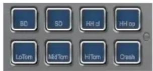
Introduction
The trigger pads in HALion Sonic can be used for two different functions. They can either trigger single notes to remote key switches, or trigger complex chords. To control the pads from a hardware controller or keyboard, each pad can be assigned to a MIDI note.
Assigning a MIDI note to a pad
A pad can be triggered by any MIDI note.
To define the desired note:
- Open the context menu on the pad.
- Select "Assign Trigger Note".
- Select the octave and note.
or
- Open the context menu on the pad.
- Select "Learn Trigger Note".
- Play the note on the remote keyboard.
As soon as the trigger note has been assigned, the corresponding key on the GUI keyboard will be shaded in blue. This key no longer plays any sounds but triggers other notes.
Removing the assignment of a pad
To remove the assigned note or MIDI controller:
- Open the context menu on the pad.
- Select "Forget Trigger Note".
Naming a pad
To indicate the functionality of a pad, you can enter a name. To edit the name:
- Right-click the “...” on the pad.
- Enter the desired name.
(e.g. KeySw1, KeySw2, ..., Amin7, Gmaj, ..., Flex1, Flex2)
- Press [Enter] on your computer keyboard to confirm the name.
Triggering chords / notes
To trigger chords with a pad, you first need to define the chord:
- Open the context menu on the pad.
- Select "Snapshot Chord" and The pad starts blinking.
- Play the MIDI notes (or press the corresponding keys on the GUI keyboard) from the chord.
-
The display keyboard keys will be shaded in blue.
-
Click the pad again to accept the chord.
- The pad now glows slightly to show that a chord has been assigned.
Triggering the pad now plays the chord.
⇒ As long as you are still in Learn mode, you can remove notes by playing them a second time.
This feature can be very useful in combination with the FlexPhraser since you can feed it with complex chords that otherwise would be impossible to play by hand.
Also, you are able to define chords containing notes that work as key switches. In this case, you can trigger the chord with a specific instrument expression.
⇒ If you add keys to a chord that works as trigger notes as well, they trigger their notes too.
Triggering key switches
To use a pad as a key switch, you simply need to assign the corresponding MIDI note to it as described above. However, if you want to remap the incoming MIDI note to another note, you can do so using the chord functionality set to a single note:
- Open the context menu on the pad.
- Select "Snapshot Chord" and the pad starts blinking.
- Play the MIDI note that shall be triggered by the pad.
Triggering the pad now sends this note even though another key is played on the keyboard.
Bypassing the pads section
To deactivate the pad functionality you can bypass them. In Bypass, only the original notes are played and no chords are triggered. To deactivate the pads section, press the Bypass switch to the right of the pads section.
Global Effects
Introduction
HALion Sonic features four AUX busses that can be used to realize classical send effects. All slots and layers, and in the case of drum or loop layers, even single instruments can send signal portions to the busses. Each bus hosts up to four insert effects which allows you to setup complex multi effects. The busses are then routed to either the main plug-in output or to one of the individual outs. The Effects page also provides access to the main output bus which also features four inserts. These can, for example, be used to add a global EQ or compressor to the signal chain.
Using the insert effect slots
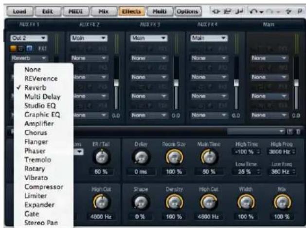
Global Effects page
Each bus and the Main bus provides four slots for insert effects. The handling is the same for all slots:
- To assign an insert effect, click the slot and select the desired effect from the menu.
- To remove an insert effect, click the slot and select "No Effect" from the menu. The effect with its current settings will be removed.
-
The on/off button above the slot deactivates the effect without removing it. This way, you can switch the effect off without losing its settings. The effect is active, when the button is lit.
-
The button next to the on/off button above the slot bypasses the effect. The bypass is active when the button is lit.
- To edit an insert effect, click the "e" button of the slot that holds the effect you want to edit. You can edit only one effect at a time. The "e" button stays lit to indicate which effect you are editing. The parameters of the respective insert effect will be displayed in the section below.
⇒ The Mix parameter of an effect inserted into an AUX bus is set to 50% by default.
Moving effects
To change the position of an effect on one bus, or even to move an effect from one bus to another:
- Drag the effect by its Label (FX1, FX2, FX3, FX4) and move it to the desired position.
- Drop it onto a slot to insert it. Existing effects will be replaced.
- Drop it between two slots to insert it in between existing slots.
Copying effects from one slot to another
To copy an effect from one slot to another:
- [Alt]-Drag the effect by its Label (FX1, FX2, FX3, FX4) over the insert slot you want to move it to.
- Drop it.
- The effect and all its settings will be copied.
Changing the output assignments
Above the insert slots, you find menus for assigning the outputs of the AUX busses.
To change the output assignment:
- Click the Output menu of the AUX bus.
- Select the desired output from the menu.
Adjusting the levels
To adjust the output level, use the fader below the level meter:
- Move the fader of the AUX bus.
- Alternatively, enter a value in the text field below the fader.
The master effect bus
The main bus works similar to the AUX busses. The only difference you will find is that the main bus has no bus output selector since it is "hard-wired" to the main plug-in output (1/2).
⇒ The Mixparameter of an effect inserted into the main bus is set to 50% by default.
Effects reference
HALion Sonic comes with a collection of high-quality studio effects. Each of the effects are described in detail below.
REVerence
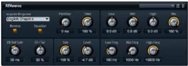
By recording an impulse in a room, you get the fingerprint of it. Convolution superimposes this fingerprint to the sound. The result is a very natural sounding reverb. This effect comes with a collection of high-quality reverb impulse responses.
Impulse
Here you select the impulse response. By selecting an impulse response you determine the basic sound character of the reverb.
Auto Gain
When this is activated, the impulse response is normalized automatically.
Reverse
Activate this to reverse the impulse response.
Predelay
This determines the amount of time between the dry signal and the onset of the reverb. The control range is from 0 ms to 500 ms. Longer predelays are usually associated with larger spaces.
Time Scaling
This scales the reverb time. The control range is from 10% to 150%. At a setting of 100% the impulse response is applied with its original length.
Size
Use this to scale the size of the room. The control range is from 10% to 150%. At a setting of 100% the impulse response is applied with its original size.
Level
Here you can adjust the level of the impulse response. The control range is from -24.0 dB to +24.0 dB.
Equalizer
You can adjust the tone color of the impulse response with a three band equalizer.
Control Description
| Low Gain Use this to set the amount of cut or boost for the low band. The control range is from -24 dB to +24 dB. |
| Low Freq This sets the frequency that i s cut or boosted by the Low Gain. The control range is from 20 Hz to 500 Hz. |
| Mid Gain Use this to set the amount of cut or boost for the mid band. The control range is -12 dB to +12 dB. |
| Mid Freq This sets the frequency that is cut | or boosted by the Mid Gain. The control range is from 100 Hz to 10000 Hz. |
| Hi Gain Use this to set the amount of cut or boost for the high band. The control range is -24 dB to +24 dB. |
| Hi Freq This sets the frequency that is cut | or boosted by the Mid Gain. The control range is from 5000 Hz to 20000 Hz. |
ER Tail Split
This sets the split point between the early reflections and the reverb tail. The control range is from 2 ms to 100 ms.
ER Tail Mix
This sets the balance between early reflections and reverb tail. The control range is from 0% to 100%. At a setting of 50% the early reflections and tail are equally loud. Settings below 50% raise the early reflections and lower the tail, in which the sound source moves towards the front of the room. Settings above 50% raise the tail and lower the early reflections, in which the sound source moves towards the back of the room.
Reverb
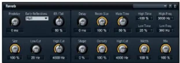
This effect is a high-quality algorithmic reverb with early reflections and reverb tail. The early reflections are responsible for the spatial impression in the first milliseconds of the reverb. For modeling different rooms you can choose from different early reflections patterns and adjust their size. The reverb tail, or late reverberation, offers parameters for controlling the room size and the reverb time. You can adjust the reverb time individually in three frequency bands.
Tail Delay
This delays the onset of the reverb tail. The control range is from 0 ms to 500 ms.
Predelay
This determines the amount of time between the dry signal and the onset of the reverb. The control range is from 0 ms to 500 ms. Longer predelays are usually associated with larger spaces.
Early Reflections
This selects the pattern of the early reflections. The early reflections pattern contains the most important delays that deliver the key information for the spatial impression of the room. The patterns are based on measurements of real rooms.
ER Tail Mix
This sets the balance between early reflections and reverb tail. The control range is from 0% to 100%. At a setting of 50% the early reflections and tail are equally loud. Settings below 50% raise the early reflections and lower the tail, in which the sound source moves towards the front of the room. Settings above 50% raise the tail and lower the early reflections, in which the sound source moves towards the back of the room.
ER Size
This adjusts the length of the early reflections pattern. The control range is from 0% to 100%. At a setting of 100% the pattern has its original length and the room sounds the most natural. At settings smaller than 100% the early reflections pattern is compressed and the room is perceived smaller.
ER Low Cut
This attenuates the low frequencies of the early reflections. The control range is from 20 Hz to 1000 Hz. The higher this value will be, the less low frequencies the early reflections will have.
ER High Cut
This attenuates the high frequencies of the early reflections. The control range is from 1000 Hz to 20000 Hz. The lower this value will be, the less high frequencies the early reflections will have.
Tail Room Size
This parameter controls the dimensions of the room. The control range is from 0% to 100%. At a setting of 100% the dimensions equal a cathedral or large concert hall. At a setting of 50% the dimensions equal a medium sized room or studio. At settings below 50% the dimensions equal small rooms or a booth.
Tail Main Time
This controls the overall reverb time of the tail. The control range is from 0% to 100%. The higher you set this value, the longer the reverb tail will decay. At a setting of 100% the reverb time is infinitely long. The Tail Main Time parameter also represents the mid band of the reverb tail.
Tail Shape
This controls the attack of the reverb tail. The control range is from 0% to 100%. At a setting of 0% the attack is more immediate, this is good for drums. The higher this value will be, the less immediate the attack will be.
Tail Density
Here you can adjust the echo density of the reverb tail. The control range is from 0% to 100%. At a setting of 100% single reflections from walls cannot be heard. The lower this value the more single reflections can be heard.
Tail High Cut
This attenuates the high frequencies of the reverb tail. The control range is from 20 Hz to 20000 Hz. The lower this value will be, the less high frequencies the reverb tail will have.
Tail High Time
This controls the reverb time for the high frequencies of the reverb tail. The control range is from -100% to +100%. For positive values, high frequencies decay longer and vice versa. Frequencies will be affected depending on the Tail High Freq parameter.
Tail Low Time
This controls the reverb time for the low frequencies of the reverb tail. The control range is from -100% to +100%. For positive values, low frequencies decay longer and vice versa. Frequencies will be affected depending on the Tail Low Freq parameter.
Tail High Freq
This sets the cross-over frequency between the mid and the high band of the reverb tail. The control range is from 2000 Hz to 20000 Hz. The reverb time for frequencies above this value can be offset from the main reverb time with the Tail High Time parameter.
Tail Low Freq
This sets the cross-over frequency between the low and the mid band of the reverb tail. The control range is from 20 Hz to 2000 Hz. The reverb time for frequencies below this value can be offset from the main reverb time with the Tail Low Time parameter.
Output Width
This adjusts the output of the reverb signal between mono and stereo. The control range is from 0% to 100%. At a setting of 0% the output of the reverb is mono. At a setting of 100% the output is stereo.
Mix
This sets the ratio between the dry and wet signal. The control range is from 0% to 100%. At a setting of 100% the output signal is fully wet.
Multi Delay
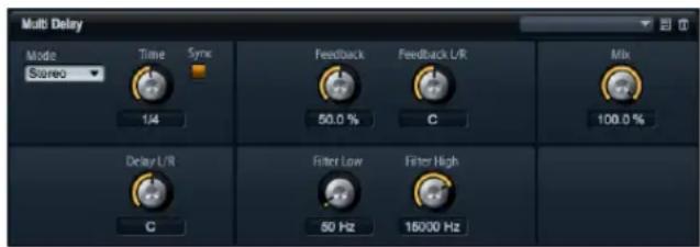
This effect delivers echoes, so-called delays, with adjustable time, feedback and filters. With Delay mode you can setup this effect as Stereo, Cross or Ping-Pong Delay. Depending on the selected mode, the echoes repeat in varying patterns across the stereo panorama. With Delay Time you set the overall time for the left and right delay. In addition, you can activate Sync to set the delay time in fractions of beats synchronized to the host tempo. The parameter Delay L/R allows you to offset the time of the left or right delay. Feedback and Feedback L/R set and offset the amount of feedback of the left and right delay respectively. Finally, there is a Low and a High Filter to adjust the tone color of the echoes.
Delay Time
This sets the overall time for the left and right delay in milliseconds. The control range is from 0 ms to 5000 ms. Use Delay L/R to shorten the time for the left or right delay. Activate Sync to set the delay time as note length.
Delay Mode
The Delay offers three different modes:
Mode Description
| Stereo This mode has two delays in parallel, one for the left and one for the right audio channel, each with a feedback path of its own. | |
| Cross This mode has two delays with cross feedback. Cross feedback means that the delay of the left channel is fed back into the right delay and vice versa. | |
| Ping-Pong This mode mixes the left and right input and sends it to hard-panned left and right delays. This way, the echoes bounce like a ping-pong ball between left and right in the stereo panorama. Hence, the name Ping-Pong Delay. |
Sync
Sync is short for synchronization. Activate this to synchronize the delay time to the host tempo. When activated, the time is set as note length with the following settings: 1/64, 1/32, 1/16T, 1/16, 1/8T, 1/16D, 1/8, 1/4T, 1/8D, 1/4, 1/2T, 1/4D, 1/2, 1/1T, 1/2D, 4/4, 5/4, 6/4, 7/4 and 8/4.
If the time of the note length exceeds the maximum delay time of 5000 ms, for example, because your song tempo is very slow, the note length will be halved internally to not exceed the maximum possible delay time.
Delay L/R
Here you can offset the time of the left or right delay from the overall delay time. The offset adjusts with a factor. A factor of 1 means the delay equals the overall delay time. A factor of 0.5 means the time is half as long as the overall delay time. To offset the left delay time, turn the control left. To offset the right delay time, turn the control right. The letter before the factor changes accordingly to "L" or "R", indicating the delay you adjust. The control range is from L x 0.0 to L x 1.0 and R x 1.0 to R x 0.0. The mid position of the control sets a factor of 1.0, which is the neutral setting.
Feedback
This sets the overall amount of feedback for the left and right delay. Feedback means the output of the delay is fed back to its input. Depending on the amount you set, the echoes repeat more or less. The control range is from 0% to 100%. At a setting of 0% you hear only one echo. At a setting of 100% the echoes repeat endlessly.
Feedback L/R
This parameter is only available for the Stereo Delay. Use this to offset the amount of feedback of the left or right delay from the overall Feedback. The offset adjusts with a factor. A factor of 1 means the amount of feedback equals the overall Feedback. A factor of 0.5 means the amount is half the overall Feedback. To offset the left feedback, turn the control left. To offset the right feedback, turn the control right. The letter before the factor changes accordingly to "L" or "R", indicating the delay you adjust. The control range is from L x 0.0 to L x 1.0 and R x 1.0 to R x 0.0. The mid position of the control sets a factor of 1.0, which is the neutral setting.
Filter Low
This allows you to attenuate the low frequencies of the delays. The control range is from 10 Hz to 1000 Hz.
Filter High
This allows you to attenuate the high frequencies of the delays. The control range is from 1000 Hz to 20000 Hz.
Mix
This sets the ratio between the dry and wet signal. The control range is from 0% to 100%. At a setting of 100% the output signal is fully wet.
Studio EQ
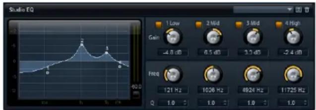
This is a high-quality 4-band parametric equalizer. With the four frequency bands, 1 Low, 2 Mid, 3 Mid and 4 High, you can shape the tone color, for example, to create a brighter or darker sound. The two midrange bands act as peak filters, while the low and high bands act as shelving filters. All bands are fully parametric with adjustable Gain, Frequency and Q factor.
Each frequency band offers the following controls:
Control Description
Gain Use this to set the amount of cut or boost for the according band. The control range is -12 dB to +12 dB.
Freq This sets the frequency that is cut or boosted by the Gain. The control range is 20 Hz to 20000 Hz.
Q Q is short for quality factor. Use this width of the midrange peak filters from wide to narrow. By increasing the Q on the low and high shelving filters you can add a dip to their shape. The control range is from 0.5 to 10.0.
To adjust the settings of the equalizer:
- Use the equalizer controls, Gain, Freq, and Q and adjust them as desired.
- To adjust Gain and Freq simultaneously, drag the points in the EQ graph in the display to the left.
Graphic EQ
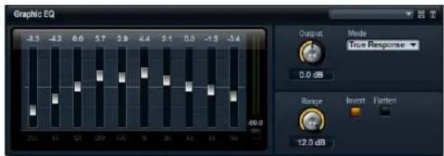
This equalizer has ten frequency bands that can be cut or boosted by up to 12dB. Each frequency band is represented by a fader. In addition, there are general controls for setting the overall range and output of the equalizer.
To cut or boost the frequency bands:
- To cut a frequency band, drag the fader of the desired band down.
- To boost a frequency band, drag the fader of the desired band up.
Output
This controls the overall output level of the equalizer. The control range is from -15 dB to +15 dB.
Range
This adjusts the maximum cut or boost in dB for all frequency bands together. The control range is from 0.0 to 12.0.
Invert
Activate this to invert the EQ curve. The frequency bands that are boosted will be cut and vice versa.
Flatten
Click this button to reset all frequency bands to 0 dB.
Amplifier
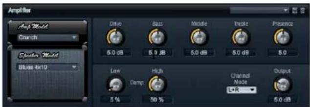
This effect emulates the sound of an amplifier with speakers. There are different amplifiers and speaker models you can combine.
Amp Model
Here you can select the type of amplifier. The sound character of the overdrive changes with the amplifier you select. To bypass the amplifier, select "No Amp".
Speaker Model
Here you select the type of Speaker model. Each model colors the sound uniquely. To bypass the model, select "No Speaker".
Drive
This adjusts the amount of overdrive. The control range is from 0.0 to 10.0.
Bass
Use this to adjust the tone color of the low frequencies. The control range is from 0.0 to 10.0.
Middle
Use this to adjust the tone color of the mid frequencies. The control range is from 0.0 to 10.0.
Treble
Use this to adjust the tone color of the high frequencies. The control range is from 0.0 to 10.0.
Presence
Use this to add brightness. The control range is from 0.0 to 10.0.
Low Damp
Use this to attenuate low frequencies of the speakers. The control range is from 0% to 100%.
High Damp
Use this to attenuate high frequencies of the speakers. The control range is from 0% to 100%.
Channel Mode
Here you can define which output channels of the amplifier delivers a distorted signal. You can set it to L (Left), R (Right) or L/R (Both). When set to L or R, the other channel provides a clean signal.
Output
This controls the output level of the amplifier. The control range is from 0.0 to 20.0.
Chorus
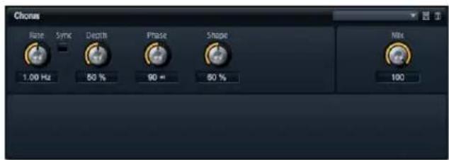
The Chorus thickens and broadens the sound by means of pitch modulation.
Rate
Use this to specify the frequency of the pitch modulation in Hertz (Hz). The control range is from 0.01 Hz to 10.0 Hz.
Sync
Sync is short for synchronization. Activate this to set the Rate in fractions of beats with the following values: 1/1, 1/2, 1/4, 1/8, 1/16, 1/32, 1/1T, 1/2T, 1/4T, 1/8T, 1/16T, 1/32T, 1/1D, 1/2D, 1/4D, 1/8D, 1/16D and 1/32D.
Depth
This sets the intensity of the pitch modulation. The control range is from 0% to 100%.
Phase
This widens the sound image of the effect from mono to stereo. The control range is from 0° to 180°.
Shape
This adjusts the characteristic of the modulation. The control range is from 0% to 100%. At a setting of 0% the pitch changes continuously, producing a steady modulation. At a setting of 100% the pitch does not change all the time, producing a less steady modulation.
Mix
This controls the mix between the dry and the wet signal. The control range is from 0% to 100%. At 100% you hear the wet signal only.
Flanger
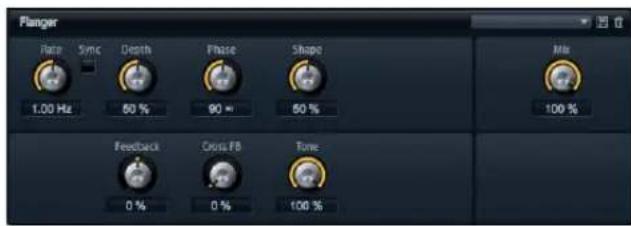
A Flanger thickens and broadens the sound by means of pitch modulation. With Feedback you can add resonances allowing for jet-like sweeps of the sound.
Rate
Use this to specify the frequency of the pitch modulation in Hertz (Hz). The control range is from 0.01 Hz to 10.0 Hz.
Sync
Sync is short for synchronization. Activate this to set the Rate in fractions of beats with the following values: 1/1, 1/2, 1/4, 1/8, 1/16, 1/32, 1/1T, 1/2T, 1/4T, 1/8T, 1/16T, 1/32T, 1/1D, 1/2D, 1/4D, 1/8D, 1/16D and 1/32D.
Depth
This sets the intensity of the pitch modulation. The control range is from 0% to 100%.
Phase
This widens the sound image of the effect from mono to stereo. The control range is from 0° to 180° . Phase also changes the characteristic of the Cross Feedback.
Shape
This adjusts the characteristic of the modulation. The control range is from 0% to 100%. You hear this best with Feedback turned on. At a setting of 0% the sound sweeps linearly up and down. At setting of 100% the sound sweeps exponentially up and down.
Mix
This controls the mix between the dry and the wet signal. The control range is from 0% to 100%. At 100% you hear the wet signal only.
Feedback
This adds resonances to the effect. The control range is from -100% to +100%.
Cross FB
This mixes the feedback of the left channel to the right channel and vice versa. To bring this parameter into effect, Feedback must be set to a value above 0%. The effect varies with the setting of the Phase parameter. The control range is from 0% to 100%.
Tone
This adjusts the tone color of the feedback. The control range is from 0% to 100%. The Feedback will be less bright the lower you set this parameter.
Phaser
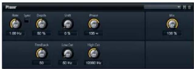
A Phaser thickens and broadens the sound by means of phase modulation. With Feedback you can add resonances to sweep the sound.
Rate
Use this to specify the frequency of the phase modulation in Hertz (Hz). The control range is from 0.01 Hz to 10.0 Hz.
Sync
Sync is short for synchronization. Activate this to set the Rate in fractions of beats with the following values: 1/1, 1/2, 1/4, 1/8, 1/16, 1/32, 1/1T, 1/2T, 1/4T, 1/8T, 1/16T, 1/32T, 1/1D, 1/2D, 1/4D, 1/8D, 1/16D and 1/32D.
Depth
This sets the intensity of the phase modulation. The control range is from 0% to 100%.
Shift
This shifts the phase modulation upwards to higher frequencies of the spectrum. The control range is from 0% to 100%.
Phase
This widens the sound image of the effect from mono to stereo. The control range is from 0° to 180° .
Low Cut
Use this to attenuate low frequencies. The control range is from 10 Hz to 1000 Hz.
High Cut
Use this to attenuate high frequencies. The control range is from 1200 Hz to 20000 Hz.
Mix
This controls the mix between the dry and the wet signal. The control range is from 0% to 100%. At 100% you hear the wet signal only.
Tremolo
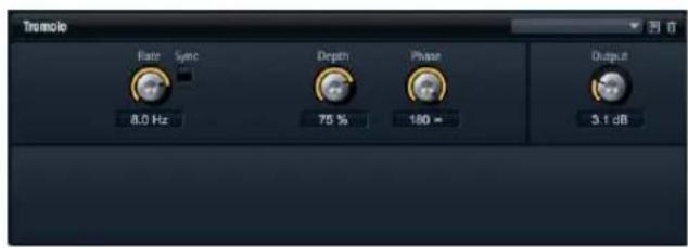
This effect produces amplitude modulation, i.e. cyclic modulation of the level of the sound.
Rate
Use this to specify the frequency of the amplitude modulation in Hertz (Hz). The control range is from 0.01 Hz to 10.0 Hz.
Sync
Sync is short for synchronization. Activate this to set the Rate in fractions of beats with the following values: 1/1, 1/2, 1/4, 1/8, 1/16, 1/32, 1/1T, 1/2T, 1/4T, 1/8T, 1/16T, 1/32T, 1/1D, 1/2D, 1/4D, 1/8D, 1/16D and 1/32D.
Depth
This sets the intensity of the amplitude modulation. The control range is from 0% to 100%.
Phase
This widens the sound image of the effect from mono to stereo. The control range is from 0° to 180° .
Output
Use this to set the output level of the Tremolo. The control range is from 0 dB to +12 dB.
Rotary
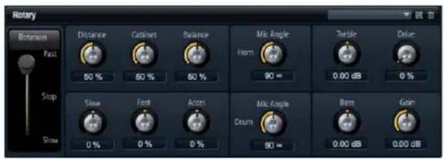
This emulates the sound of a vintage rotary speaker completely with amplifier, horn, drum and cabinet. By emitting the sound via a rotating horn and drum the rotary speaker produces a Doppler effect that thickens the sound. The horn and drum rotate at variable speed producing different amounts of Doppler effect. The amplifier of the rotary speaker adds a warm sounding distortion and the horn, drum and cabinet color the sound uniquely. The horn and drum are recorded via (virtual) microphones that can be set to different angles to broaden the sound image. Typically, rotary speakers are used with electric organs.
Rotation Speed
Use this to switch the rotation speed of the horn and drum between Slow, Fast and Stop. At the Fast setting the Doppler effect is stronger than at the Slow setting. At the Stop setting there is no Doppler effect because the drum and horn do not rotate. Since the horn and drum accelerate and decelerate at different speeds the transition from Slow to Fast and vice versa sounds the most interesting.
Distance
Here you set the distance of the microphones from the horn and drum. The control range is from 0% to 100%. The amplitude modulation of the sound decreases with the distance of the microphones. Set this to higher values for less amplitude modulation.
Cabinet
The horn and drum sound different when recorded through the louvers of the cabinet. Use this to color the horn and drum with the sound of the cabinet. The control range is from 0% to 100%. At a setting of 100% you get the full sound of the cabinet.
Balance
Here you adjust the balance between the horn and drum microphones. The control range is from 0% to 100%. At a setting of 0% you hear only the drum. At a setting of 100% you hear only the horn. The unity setting is at 50%.
Slow Speed
This adjusts the slow speed of the horn and drum together. The control range is from -100% to +100%. At a setting of -100% the speed is two times slower than at 0%. At a setting of +100% the speed is two times faster than at 0%.
Fast Speed
This adjusts the fast speed of the horn and drum together. The control range is from -100% to +100%. At a setting of -100% the speed is two times slower than at 0%. At a setting of +100% the speed is two times faster than at 0%.
Accel
Accel is short for acceleration. Use this to adjust the acceleration time for raising and lowering the rotation speed of the horn and drum. The control range is from -100% to +100%. At a setting of -100% the time is four times faster. At a setting of +100% the time is four times slower.
Horn Mic Angle
This adjusts the stereo spread of the horn microphones. The control range is from 0° to 180° . At a setting of 0° the sound image is monophonic. At a setting of 180° the sound image is fully stereo.
Drum Mic Angle
This adjusts the stereo spread of the drum microphones. The control range is from 0° to 180° . At a setting of 0° the sound image is monophonic. At a setting of 180° the sound image is fully stereo.
Treble
Use this to adjust the tone color of the high frequencies. The control range is from -12 dB to +12 dB.
Drive
Here you can adjust the distortion of the amplifier. The control range is from 0% to 100%. At a setting of 100% you get maximum distortion.
Bass
Use this to adjust the tone color of the low frequencies. The control range is from -12 dB to +12 dB.
Gain
Use this to set the output level of the Rotary Speaker. The control range is from -12 dB to +12 dB.
Vibrato
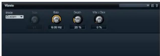
This effect emulates the chorus and vibrato effects of vintage organs. The Vibrato thickens the sound by means of pitch modulation. The effect gives direct access to the classic chorus and vibrato settings C1, C2 and C3 and V1, V2 and V3. In addition, there is a Custom mode that allows you to adjust the amount of chorus or vibrato freely.
Type
Here you can select the classic chorus and vibrato settings C1, C2 and C3 and V1, V2 and V3. The control is only available when Custom mode is switched off.
Custom Mode
Activate this to adjust the chorus and vibrato settings freely with the Rate, Depth and Mix controls.
Rate
Use this to specify the frequency of the pitch modulation in Hertz (Hz). The control range is from 0.01 Hz to 10.0 Hz.
Depth
This sets the intensity of the pitch modulation. The control range is from 0% to 100%.
Vibr/Chor
This controls the mix between the vibrato and the chorus signal. The control range is from 0% to 100%. At 100% you hear the chorus effect only.
Compressor
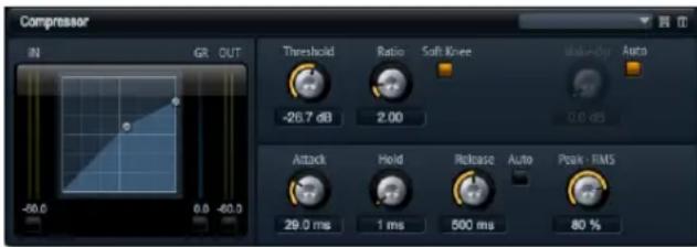
Compressors reduce the dynamic range of a sound. This way, the sound gains headroom. You can use this extra headroom to make the overall sound louder again. The graphical control to the left indicates the compression curve. You can edit the Threshold and Ratio graphically with the handles of this control. The input and output VU meters indicate the level before and after the compression. The Gain Reduction meter indicates the current attenuation of the level.
To edit the Compressor graphically:
- In the graphical control, drag the handles up and down to edit the Threshold and Ratio respectively.
- Drag the Threshold handle up to raise it. Drag the handle down to lower the Threshold.
- Drag the Ratio handle up to decrease it. Drag the handle down to increase the Ratio.
Threshold
Use this to set the Threshold in dB. The control range is from -60.0 dB to 0.0 dB. Sounds that are louder than the Threshold will be reduced in gain. Sounds below the Threshold stay untreated.
Ratio
This adjusts the amount of gain reduction for sounds that are louder than the Threshold. The control range is from 1.0 to 8.0, always to 1. The higher the ratio the more the output will be lowered. For example, if the ratio is set to 2:1 and the amplitude of the sound is 4 dB above the Threshold, the output will be lowered by 2 dB. If the amplitude is 8 dB above the Threshold, the output will be lowered by 4 dB. The same example with a ratio of 4:1 would lower the output by 3 dB and 6 dB respectively.
Soft Knee
Activate this to change the characteristic of the compression curve from Hard to Soft Knee. Hard and Soft Knee describes if the angle around the Threshold has a hard edge or soft curvature. With Soft Knee activated, the compression kicks in less suddenly.
Make-Up
Depending on the set Threshold and Ratio, the sound loses gain (indicated by the Gain Reduction meter). You can use the Make-up Gain to make the overall sound louder again. The control range is from 0.0 dB to 24.0 dB.
Auto Make-Up Gain
This calculates the gain loss from the Threshold and Ratio settings and sets the Make-up Gain automatically. The Make-up potentiometer becomes dark while Auto Make-up Gain is active.
Attack
This determines how fast the Compressor reacts to sounds that exceed the set Threshold. The control range is from 0.1 ms to 100.0 ms. The longer the time, the longer the period will be for reducing the gain to the set Ratio. In other words, with longer times the onset of sounds exceeding the Threshold pass through unprocessed.
Hold
This sets a guaranteed time over which the compression will be applied after the sound exceeded the set Threshold. The control range is from 0 ms to 2000 ms.
Release
This determines how fast the Compressor reacts to sounds that fall below the set Threshold. The control range is from 10 ms to 1000 ms. The longer the time, the longer the period will be for returning back to the original level.
Auto Release
Activate this to set the Release time automatically. The Compressor analyzes the input sound continuously to find the optimal Release time for you. The Release potentiometer becomes dark while Auto Release is active.
Peak - RMS
Here you can adjust the loudness sensing of the Compressor freely between Peak and RMS. The control range is from 0% to 100%. At a setting of 0% the Compressor uses Peak sensing only and at 100% RMS sensing only. Peak means that the Compressor senses directly the peak level of the sound. RMS is short for root mean square, a statistical measure for the amplitude of sounds. RMS means that the Compressor senses the average power of the sound. Peak sensing responds faster than RMS sensing. Typically, Peak sensing is used for transient and RMS sensing for sustained sounds.
Limiter
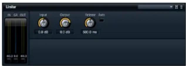
The Limiter prevents the sound from exceeding the set output level, for example, to avoid clipping in following effects. The input and output VU meters indicate the level before and after the Limiter. The Gain Reduction meter in the middle indicates the current attenuation of the level.
Input
This adjusts the input level of the sound. The control range is from -24 dB to +24 dB. By increasing the input level you can drive the sound more and more into limiting.
Output
This sets the maximum output level of the sound. The control range is from -24 dB to +6 dB.
Release
This sets the time the gain needs for returning to its original level. The control range is from 0.1 ms to 1000.0 ms. The longer the time, the longer the period will be for returning back to the original level.
Auto Release
Activate this to set the Release time automatically. The Limiter analyzes the input sound continuously to find the optimal Release time for you. The Release potentiometer becomes dark while Auto Release is active.
Expander
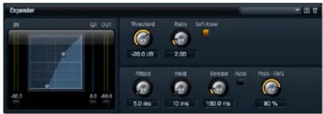
Expanders reduce the output level in relation to the input level for signals below the set Threshold. This is useful, when you want to enhance the dynamic range or reduce the noise in quiet passages. The graphical control to the left indicates the expansion curve. You can edit the Threshold and Ratio graphically with the handles of this control. The input and output VU meters indicate the level before and after the expansion. The Gain Reduction meter indicates the current attenuation of the level.
To edit the Expander graphically:
- In the graphical control, drag the handles up and down or left and right to edit the Threshold and Ratio respectively.
- Drag the Threshold handle up to raise it. Drag the handle down to lower the Threshold.
- Drag the Ratio handle left to decrease it. Drag the handle right to increase the Ratio.
Threshold
Use this to set the Threshold in dB. The control range is from -60.0 dB to 0.0 dB. Sounds that are softer than the Threshold will be reduced in gain. Sounds above the Threshold stay untreated.
Ratio
This adjusts the amount of gain reduction for sounds that are softer than the Threshold. The control range is from 1.0 to 8.0. The higher the ratio the more the output will be lowered. For example, if the ratio is set to 2:1 and the amplitude of the sound is 4 dB below the Threshold, the output will be lowered by 2 dB. If the amplitude is 8 dB below the Threshold, the output will be lowered by 4 dB. The same example with a ratio of 4:1 would lower the output by 3 dB and 6 dB respectively.
Soft Knee
Activate this to change the characteristic of the expansion curve from Hard to Soft Knee. Hard and Soft Knee describes if the angle around the Threshold has a hard edge or soft curvature. With Soft Knee activated, the expansion kicks in less suddenly.
Attack
This determines how fast the Expander reduces the gain when the sound falls below the set Threshold. The control range is from 0.1 ms to 500.0 ms. The longer the time, the longer the period will be for reducing the gain.
Hold
This sets a guaranteed time over which the expansion will be applied after the sound falls below the set Threshold. The control range is from 0 ms to 2000 ms.
Release
This determines how fast the Expander raises the gain after the sound exceeds the set Threshold. The control range is from 0.1 ms to 1000 ms. The longer the time, the longer the period will be for raising the gain again.
Auto Release
Activate this to set the Release time automatically. The Expander analyzes the input sound continuously to find the optimal Release time for you. The Release potentiometer becomes dark while Auto Release is active.
Peak - RMS
Here you can adjust the loudness sensing of the Expander freely between Peak and RMS. The control range is from 0% to 100%. At a setting of 0% the Expander uses Peak sensing only and at 100% RMS sensing only. Peak means that the Expander senses directly the peak level of the sound. RMS is short for root mean square, a statistical measure for the amplitude of sounds. RMS means that the Expander senses the average power of the sound. Peak sensing responds faster than RMS sensing. Typically, Peak sensing is used for transient and RMS sensing for sustained sounds.
Gate
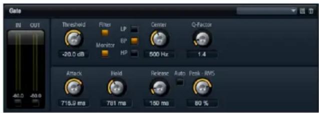
The Gate passes sound only to its output if the input sound exceeds the set Threshold. Sounds below the Threshold will be silenced. An internal side chain filter allows you to analyze a filtered version of the input sound instead. This way, the Gate senses only certain frequencies of the input sound.
Threshold
Use this to set the Threshold in dB. The control range is from -60.0 dB to 0.0 dB. Sounds that are louder than the Threshold will be reduced in gain. Sounds below the Threshold stay untreated.
Side Chain
This activates the internal side chain filter. When activated, the input sound is filtered before it is analyzed. The Gate opens only if the filtered sound exceeds the set Threshold. The filter controls turn dark when it is inactive.
Filter Type
Here you select the filter type for the side chain filter. Select high-pass (HP) to sense high, band-pass (BP) to sense mid, and low-pass (LP) to sense low frequencies only.
Monitor
Activate this to listen to the sound of the side chain filter. The Gate will be inactive while the Monitor is activated.
Frequency (LP, BP, HP)
Here you can activate one of three cutoff frequencies of the side chain filter.
Q-Factor
Activate this to adjust the bandwidth of the band-pass filter from wide to narrow. The control range is from 0.001 to 10.0.
Attack
This determines how fast the Gate opens when the sound exceeded the set Threshold. The control range is from 0.1 ms to 1000.0 ms. The longer the time, the longer the period will be for the sound to fade in.
Hold
This sets a guaranteed time over which the Gate stays open after the sound exceeded the set Threshold. The control range is from 0 ms to 2000 ms.
Release
This determines how fast the Gate closes after the sound falls below the set Threshold. The control range is from 10 ms to 1000 ms. The longer the time, the longer the period will be for the sound to fade out.
Peak - RMS
Here you can adjust the loudness sensing of the Gate freely between Peak and RMS. The control range is from 0% to 100%. At a setting of 0% the Gate uses Peak sensing only and at 100% RMS sensing only. Peak means the Gate senses directly the peak level of the sound. RMS is short for root mean square, a statistical measure for the amplitude of sounds. RMS means the Gate senses the average power of the sound. Peak sensing responds faster than RMS sensing. Typically, Peak sensing is used for transient and RMS sensing for sustained sounds.
Auto Release
Activate this to set the Release time automatically. The Gate analyzes the input sound continuously to find the optimal Release time for you. The Release potentiometer becomes dark while Auto Release is active.
Pan
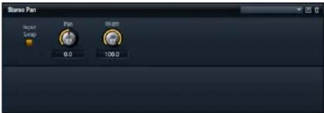
This effect allows you to set the stereo position and width of the signal.
Input Swap
Activate the Input Swap option if you want to swap the stereo channels.
Pan
Here you can set the pan position of the signal. The panning works for mono and stereo input signals.
Width
This parameter allows you to adjust the stereo width of the signal from stereo down to mono.
MediaBay
Load page - MediaBay
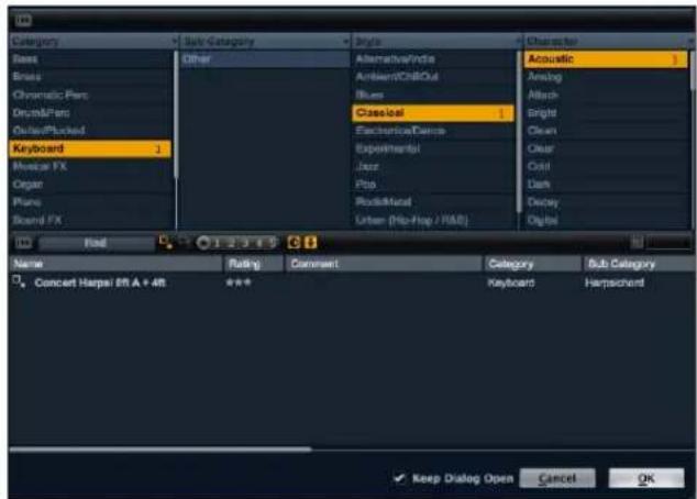
The integrated MediaBay browser view gives you a quick and comfortable access to all HALion Sonic presets such as multis, program and the various layer presets. It is divided into two sections. In the upper section you can define which kind of sounds you want to look for. The lower section presents the corresponding result list. You can drag the upper limit of the result list to adjust the size relation between the two sections.
Loading programs
To load a program into one of the 16 slots, you have three possibilities:
- Select the slot into which you want to load the program. Then double-click the program in the result list to load it.
- Drag the desired program from the result list and drop it onto the slot in which you want to have it loaded.
- Right-click the presets and select "Load Preset into selected slot" from the menu.
Loading multis
There are three ways to load multi presets:
- Double-click the multi in the result list to load it.
-
Drag the multi from the result list and drop it onto the multi slot above the Multi Program Rack.
-
Load the multi from the Cubase/Nuendo (or other sequencer host) plug-in header using the integrated preset loading methods.
When working with other host applications, you can use their preset mechanisms to save and load plug-in presets. However, there are no factory presets for the various plug-in formats. Use the built-in MediaBay browser to get access to all the factory multi presets.
Loading layers
HALion Sonic allows you to load layers directly into a program slot. This is done exactly the way you load programs. By doing so, HALion Sonic creates a new program and loads the layer to the first layer of the new program.
To load a layer as a part of a program, you need to go to the Program page of the Edit section where you can see the four layer slots.
- Click on the triangle button in the layer slot to directly open MediaBay dialog.
- Double-click the layer to load it.
- By default, the dialog closes and the layer is loaded. If you want to keep the dialog open to try several layer presets, check the corresponding option in the bottom of the dialog.
Deleting presets
To delete a preset:
- Select the desired preset.
- Right-click it to open a context menu.
- Select "Delete".
Importing presets
You can import existing program presets from any file location using the Explorer (Win) or Finder (Mac). To import presets:
- Select the desired preset in the Explorer/Finder.
- Drag it to the Load page and drop it.
- The imported presets will be copied to your user folder.
Category search
You can comfortably search for presets that match up to four search criteria by using the configurable search columns.
The easiest way is to begin by using the standard columns Category, Sub Category, Style and Character. By clicking on specific tag values in the tag columns, you define the search filter. Only the files that match the selected tag values will be displayed in the result list. Select more tag values from other columns to further refine your search.
By default, the first two tag columns are set to "Category" and "Sub Category". These tags are directly linked to each other: for each Category value, there are a number of Sub Category values. Changing to a different Category value in the first tag column allows for different values in the Sub Category column. You will find the same dependency for Style and Sub Style attributes.
If you want to search for different criteria, click on the column header to select the desired tag first. Then select the search values.
Result list
Columns
The columns of the result list show all the meta data information for the presets that matches the query, specified in the Category search section above.
You can define which columns to show and adapt the column order inside the result list by dragging the table header to the desired position. Furthermore, you can use the column headers to change the sorting order of the list entries. The triangle icon inside the column header shows which column is currently controlling the sorting and in which direction. You can sort the entries either in ascending or in descending order.
Setup result columns

Click on the "Setup Result Columns" button in the toolbar of the result list to open a menu. Here you can select which meta data columns shall be displayed. Selecting a column adds to the end of the list. You can then position the new column by dragging it to the desired position.
Preset types
There are three types of presets:
Type Description
Multi All settings of the complete plug-in.
Program All settings of a program consisting of up to four layers.
Layer One single layer (synth, sample, instrument, drum or loop layer).
To distinguish between the different preset types, each type comes with its specific icon.
View filters
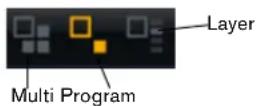
The toolbar of the result list features three filter buttons that allow you to define which type of presets shall be displayed. There is a filter button for each type of multi, program and layer. Depending on what type of preset you want to load, you can activate one of them. By default the filter is set to program.
Rating filter
You can limit the search result to presets that have a certain rating level. The rating filter slider allows you to define the minimum rating level.
Text search filter

The text search field in the result list toolbar allows you to quickly enter a name fragment to find all presets that contain that specific fragment. The result list updates immediately, and the Category search section above shows all categories that contain presets with what matches the text search.
Reset the search filter

If you want to remove the text from the search field simply click the Reset button on the left side of the text field.
Factory / User filter
These two filter buttons allow you to define whether you want to see all presets, only the Factory, or only your user presets.
The result counter
The number of presets that matches the specified search criteria is displayed in the text field in the right corner of the result list toolbar.
Tagging presets
Each preset can be described by using a predefined set of attributes (also called "tags"). These tags can be set in the tagging section of the save dialog or can directly be set in the result list.
- Click on the value field you want to set to open a menu (dialog).
- Select the desired value.
⇒ The tag values are directly written into the corresponding preset files. However, this is not possible for write protected factory content. In this case, the meta data will be saved with HALion Sonic's MediaBay database.
Tags
The following attributes can be set directly in the result list or save dialog:
Tag: Editing method:
Media
Name Display only.
Rating Drag to set the rating.
| Comment Click to select, double-click to edit. | ||
| Content Summary Click to select, double-click to edit. | ||
| Write Protection Display only, use context menu to set protection. | ||
| Library Name Click to select, double-click to edit. | ||
| Library Manufacturer Click to select, double-click to edit. | ||
| Author Click to select, double-click to edit. | ||
| Musical | Category Click to select. | |
| Sub Category Click to select. | ||
| Style Click to select. | ||
| Sub Style Click to select. | ||
| Character | Click to open an editor dialog. | |
| Tempo | Click to select, double-click to edit. | |
| Bars & Beats | Click to select, double-click to edit. | |
| Signature | Click to select, double-click to edit. | |
| Key | Click to select. | |
| GM Sound | Click to select. | |
Setting the character tags
Unlike the other tags which can be set by using a menu or by typing in the desired word, the character tags can be set through a dedicated editor. This editor provides a list of opposites which allows you to describe the character of a sound.
To set a character turn on the desired attributes: The preview line in the lower section of the dialog shows you how the characters appear later on in the result list.
Tagging with the save dialog
When you save a preset, the save dialog opens and shows the tagging editor section on the right side. Here you can easily edit your tags before saving the preset. To make it even simpler, you can first click an existing preset file in the file list on the left to copy its name and all its tags, then make the changes the new preset requires, modify the preset name and save it.
Options page
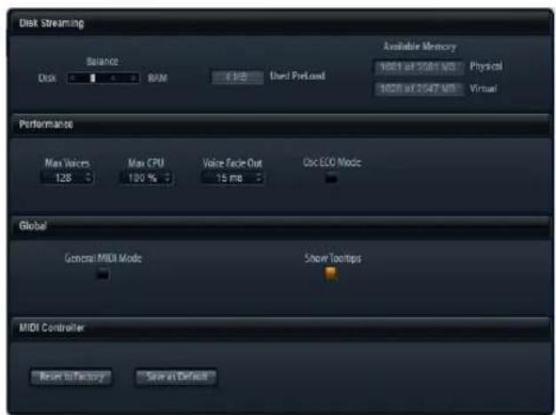
The settings on the Options page
Disk Streaming
Some of the programs come with up to 1 GB of samples, such as the acoustic piano. That is a large amount of data and your computer cannot load all samples completely into the RAM, especially if you are using all of the 16 slots. Instead, HALion Sonic loads only the first milliseconds of each sample into the RAM and constantly loads more manageable portions from hard disk while you play. Because the hard disk has to work harder for every additional note you play, it is a good idea to load as much material as possible into the RAM beforehand. This, of course, leaves less RAM for other applications. For an optimum performance of your system, you can balance the RAM versus the hard disk usage of HALion Sonic.
Balancing Disk vs. RAM
With this slider, you can balance the hard disk versus the RAM usage.
- If you need more RAM for other applications, drag the slider to the left towards the Disk setting.
- If your hard disk is not supplying data fast enough, drag the slider to the right towards the RAM setting.
The memory display will be updated accordingly.
⇒ If you experience no problems with the system performance, leave this setting as it is.
⇒ The Disk vs. RAM always applies to all plug-in instances. It will not be saved with the project. You need to set this up only once for your computer system.
Performance
Here you find settings to optimize the overall CPU performance of HALion Sonic.
Max Voices
This allows you to specify a total number of voices that a plug-in instance of HALion Sonic can playback. As soon as this limit is reached, HALion Sonic starts stealing voices. The control range is from 1 to 512 voices.
Max CPU
To avoid clicks from CPU overloads, you can specify a maximum limit for the CPU load of the plug-in instance. HALion Sonic steals voices automatically when this limit is exceeded. The control range is from 10% to 100%. A setting of 100% means that the Max CPU is switched off.
⇒ Because HALion Sonic needs some time to react, you can get CPU peaks that exceed the limit you set, which can lead to artifacts such as audio drop-outs. If you set the Max CPU a bit lower than actually needed, you are safe again.
Voice Fade Out
Here you adjust the time to fade out voices that need to be stolen because the Max Voices setting or the Max CPU of the plug-in instance has been reached. The control range is from 5 ms to 100 ms.
Osc ECO mode
Activate this to run the oscillators of synth layers in ECO mode. The oscillators use less CPU at the cost of producing more aliasing at higher pitches. When activated, you are able to play more voices with synth layers.
Global
Here you find common settings of HALion Sonic.
Show Tooltips
When you move the mouse over a control, a small help text will be shown. Deactivate Show Tooltips to avoid this.
→ Show Tooltips will not be saved with the project. You need to set this up only once for your system.
MIDI controller
You can save your customized MIDI controller assignments as default or restore the factory MIDI controller assignments.
Resetting to factory
To restore the factory MIDI controller assignments:
-
Click the "Reset to Factory" button.
-
Click "Yes" to restore the mapping or "No" to cancel.
Saving as default
To save the current MIDI controller assignments as default:
- Click the "Save as Default" button.
Now, each time you load a new instance of the plug-in, your customized MIDI controller mapping will be loaded as default.
⇒ "Save as Default" does not include any of the MIDI controller assignments of the AUX FX.
The current MIDI controller mapping will also be saved with each project. This way, you can transfer your settings to other systems. The project includes the MIDI controller assignments of the AUX FX as well.
Multi Chain
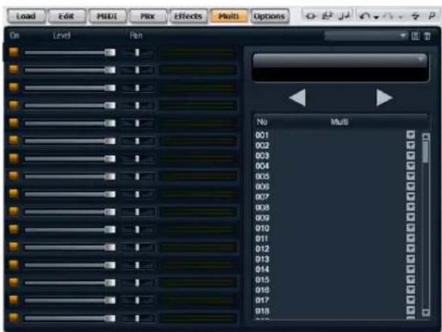
Introduction
HALion Sonic comes with a special Multi Chain feature which allows you to set up a list of 128 multis which you can either step through manually or load by program change. This feature is particularly useful when performing live on stage. It allows you, for example, to setup up a list of sounds that follows the order of their appearance during your performance.
To use the Multi Chain mode:
-
Switch to the Multi page.
-
Load an existing Chain using the preset controls in the title bar.
Setting up a Multi Chain
-
Switch to the Multi page.
-
Click on the triangle button of the desired list entry to open the MediaBay dialog.
-
Select a multi and click "OK".
-
Repeat the same procedure for all multis that shall be part of the list.
You can now step through the list by clicking the left (Previous) and right (Next) arrow switches, or select a particular list entry with the mouse. The corresponding multi will be loaded. You can also assign arbitrary MIDI controllers to remote the switches with a hardware controller by right-clicking a switch and selecting the desired controller.
If you are using a knob, slider or the mod wheel, any transition from the lower to the upper half switches to the next multi. Controls such as foot pedal or switch step forward as well. When both buttons (Previous/Next) are assigned to the same slider, knob or mod wheel control, HALion Sonic transforms a transition from the middle to the top quarter into a next-command, a transition from the middle to the lower quarter into a previous-command.
Changing the order of the chain
You can reorder the list entries by dragging them to a new list position. The insert position will be indicated.
Clearing the chain
To remove all entries from the list:
-
Click the options triangle in the Name display.
-
Select "Clear Multi Chain".
Removing a multi from the Chain
To remove the single multi from the list:
-
Click the options triangle in the Name display.
-
Select "Remove Selected Multi".
Assigning MIDI controllers to the Previous/Next buttons
To switch through the multi list you can also use MIDI controllers. This can be, for example, a footswitch, a knob, fader or the mod wheel. To enable this function, you have to assign the desired controller first.
-
Right-Click on one of the arrow keys to open the context menu.
-
Select "Learn CC".
-
Change your hardware controller.
To remove the MIDI controller, open the context menu and select "Remove CC".
Additional controls when using HALion Sonic as a standalone instrument

At the top of the program window you find some additional controls for using HALion Sonic as a standalone instrument.
For information on how to set up HALion Sonic as a standalone instrument see the section "HALion Sonic standalone" on page 9.
The Key Commands dialog
You can assign key commands to most operations that can be performed via the standalone panel of HALion Sonic. The Key Commands dialog lists all available commands and any key commands assigned to them. The commands are arranged in a hierarchical folder structure, similar to the Windows Explorer and Mac OS Finder. When you open a category folder by clicking the plus sign beside it, the items and functions are displayed with any currently assigned key commands.
To set up a key command, proceed as follows:
- In the top left corner of the standalone panel, click on the button to the right of the MIDI input pop-up menu. The Key Commands dialog opens.

...to open the Key Commands dialog.
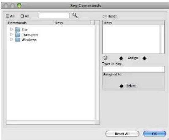
- In the Commands list to the left, select a Category.
- Click the plus sign to open the Category folder and display the items it contains.
Note that you can also click the "global" plus and minus signs in the top left corner to open and close all Category folders at once.
- In the list, select the item to which you want to assign a key command.
Already assigned key commands are shown in the Keys column as well as in the Keys section in the top right corner.
You can also search for a specific function by entering its name in the search field at the top of the dialog and clicking the search button (the magnifying glass button).
5. When you have found and selected the desired item, click in the "Type in Key" field and enter a new key command.
You can choose any single key or a combination of one or several modifier keys ([Alt]/[Option], [Ctrl]/[Command], [Shift]) plus any key.
- Click the Assign button above the field to assign the key command to the function.
The new key command is displayed in the Keys list.
-
Click OK to close the dialog.
-
If a key command is already used for another function, a message is displayed allowing you to reassign the key command or cancel the operation.
- You can set up several key commands for the same function.
- To delete a key command, select the corresponding command, select the key command in the Keys list and click the Delete button (the trash icon).
Selecting the MIDI input and the audio outputs
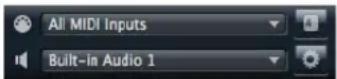
In the upper left corner of the plug-in panel in standalone mode, you find two pop-up menus for selecting the MIDI input and the main audio output of the plug-in.
The MIDI input pop-up menu lists all MIDI devices that are installed on your system.
- Open the MIDI input pop-up menu to select the MIDI device you want to use.
The orange MIDI Activity LED in the upper left corner of the plug-in indicates incoming MIDI messages via the currently selected MIDI input. The LED lights up on note-on and controller messages. This way, you can check if the plug-in and your MIDI keyboard are connected to the same MIDI device input.
The Audio output pop-up menu lists all outputs of the selected ASIO Device.
- Open the Audio output pop-up menu to select an audio output for the main stereo channel of the plug-in. If you select an audio output, the front and rear channels are set to incrementing audio output ports – e. g. 1, 2, 3, 4 or 5, 6, 7, 8.
Pressing [Alt]/[Option]-[Shift] and selecting an audio output assigns the audio outputs in pairs to the front and rear channels - e. g. 1, 2, 1, 2 or 5, 6, 5, 6.
⇒ Use the Preferences dialog to select the ASIO device and other audio outputs. For information on the Preferences dialog, see "The Preferences dialog" on page 9.
Scratch pad

The scratch pad allows you to record and play back MIDI files in standard MIDI file format (file name extension .mid). You can load existing MIDI files and you can record your own files and save them. The transport section provides buttons for play, stop, record and loop. The display shows the song position, the tempo and the time signature of the MIDI file. In addition, there is a metronome which you can use for recording and practicing.
⇒ The scratch pad is able to play back multi track MIDI files sending notes on all 16 MIDI channels. It also sends MIDI program change when a MIDI file is loaded.
Using the transport controls
- Click the Play button to start playback of the MIDI file. Playback always starts at the song position.
- Click the Stop button to pause the MIDI file at the current position.
Click the Stop button twice to reset the song position to the start. - Click the Record button to start recording.
- Click the Loop button to play the whole MIDI file in a loop.
Loading a MIDI file
To load a standard MIDI file (.mid), proceed as follows:
- Click the Load File button below the transport buttons.
- In the file dialog that appears, select the desired file.
- Click Open to load the MIDI file.
Saving a MIDI file
To save the performance you recorded as a MIDI file, proceed as follows:
- Click the Save File button (the disk icon) below the transport buttons.
- In the file dialog that appears, specify a location and a file name.
- Click Save to store the MIDI file.
The info icon
To check which MIDI file is currently loaded, point with the mouse at the info icon in the upper left corner of the song position display. A tooltip appears, showing the name of the MIDI file.
Using the MIDI channel filter
When a multi-track MIDI file is loaded, you can decide whether "all" or only the events of a specific MIDI channel are played back. The control can be found to the right of the info icon in the song position display.
Song position
The song position fader indicates the position of the transport. Above the song position fader, the position is displayed numerically.
⇒ After loading a MIDI file, the display shows the full length of the file and the song position fader is positioned at the end. However, playback starts from the beginning when you click Play.
- To move the transport to a different song position, drag the song position fader to the desired position.
- To change the format, click the time format symbol in the top right corner of the display to switch between the time formats. When "Time" format is selected, a clock is displayed. In "Bars" format a note is displayed.
Tempo and Time Signature
Below the song position display, you find the Tempo and Time Signature fields which provide the plug-in with tempo and time signature information. In standalone mode, such information is not available via a host application. In this case, the settings are used by the scratch pad and the metronome.
Option Description
| Tempo Track/ Fixed | Set this to “Track” to follow the original tempo of the MIDI file. Set this to “Fixed” to specify a tempo manually. |
| Tempo Value | Determines the tempo of the MI DI file. The control range is from 1.000 BPM to 300.000 BPM. |
| Adjust Tempo | When the Tempo Track option is selected, an additional control is displayed that allows you to scale the playback relatively to the original tempo of the MIDI file. The control range is from 0.5x (-50%) to 2x (+100%) of the original tempo. |
| Sign. (time signature) | Determines the time signature of the plug-in. You can enter the desired signature as a fraction, e. g. 3/4, 6/8, 4/4, etc. |
Recording your performance
- Click on the record symbol below the Record button to select the desired record mode from the pop-up menu:
Option Description
Direct The recording starts immediately when you click the record button.
MIDI The recording starts with the first MIDI note.
Count In 1 The recording starts after a count-in of one bar.
Count In 2 The recording starts after a count-i n of two bars.
- Click the Record button to start the recording.
- When you are done recording, press the stop button.
- Now you can save your performance as a MIDI file, see "Saving a MIDI file" on page 94.
⇒ To indicate that the recordingis running, the song position fader is being animated (a small bar moves from left to right).
Activating the metronome
To select the playback mode of the metronome, click the Metronome button. You can select one of the following modes from the pop-up menu:
Option Description
Off The metronome is switched off.
Count In The metronome plays onl y during the count-in of a re-cording.
On The metronome is always switched on.
The volume control next to the metronome icon allows you to set the volume of the metronome. The Preferences dialog also provides metronome settings.
Volume
Use this control to set the overall volume of the outputs of the standalone plug-in. This includes the volume of the main outputs, the rear outputs and the output of the metronome.
MIDI controllers
Using MIDI controllers
You can assign the parameters volume, pan, mute, solo, send FX 1 – 4 and the quick controls of each slot to a MIDI controller. In addition to the slot parameters, you can also assign the parameters of the AUX FX. By default, volume, pan, send FX 1 – 4 and the program quick controls are already assigned. You can customize this factory MIDI controller mapping by assigning your own MIDI controllers with a convenient learn function. This way, you can adapt the mapping to your MIDI keyboard or controller. To provide much better control, you can set the minimum and maximum range for each assignment separately.
Assigning MIDI controllers
To assign a MIDI controller to a parameter:
- Right-click (Win) or [Ctrl]+click (Mac) the control you want to remote.
- Select "Learn CC" from the menu.
- On your MIDI keyboard or controller, use the potentiometer, fader, or button.
⇒ The next time you right-click (Win) or [Ctrl]+click (Mac) the control, the menu shows the assigned MIDI controller.
⇒ You can assign the same MIDI controller multiple times to different parameters. However, you cannot assign different MIDI controllers to the same parameter.
Unassigning MIDI controllers
To unassign a MIDI controller assignment:
- Right-click (Win) or [Ctrl]+click (Mac) the control you want to unassign.
- Select "Forget CC" from the menu.
Setting the minimum/maximum range
You can set the minimum and maximum range of the parameter for each assignment separately. This way, you have much better control over the parameter, for example, when you are performing on stage.
To set the minimum range of the parameter:
- Set the parameter to the desired minimum value.
- Right-click (Win) or [Ctrl]+click (Mac) the control.
- Select "Set Minimum" from the menu.
To set the maximum range of the parameter:
- Set the parameter to the desired maximum value.
- Right-click (Win) or [Ctrl]+click (Mac) the control.
- Select "Set Maximum" from the menu.
Assigning MIDI controllers to AUX FX
You can assign the parameters of the AUX FX to MIDI controllers as well. Unlike the slots, the AUX FX do not have a MIDI Port and Channel of their own. Instead, they listen to any incoming MIDI controller message regardless of the MIDI channel (Omni mode). Therefore, if you assign a parameter to a MIDI controller, you should use a controller number which is not already in use by any of the assignments you made on the slots.
- To assign a MIDI controller, load the effect, right-click the parameter and assign the controller you wish as described above.
- If you unload the effect or replace the effect by another one, the MIDI controller assignment of this effect will be lost.
Saving a MIDI controller mapping as default
After you customized the factory MIDI controller assignments, you can save them as default.
To save the current MIDI controller mapping as default:
- Go to the Options page.
- Click "Save as Default" in the MIDI controller section.
Now, each time you load a new instance of the plug-in, your customized MIDI controller mapping will be available as default.
→ "Save as Default" does not include any of the MIDI controller assignments of the AUX FX.
⇒ The current MIDI controller mapping will also be saved with each project. This way, you can transfer your settings to other systems. The project also includes the MIDI controller assignments of the AUX FX.
Restoring the factory MIDI controller assignment
To restore the factory MIDI controller assignments:
- Go to Options page.
- In the MIDI controller section, click "Reset to Factory".
- Click "Yes" to restore the mapping or "No" to cancel.
Automation and factory MIDI controller assignments
The following parameters on the plug-in surface are available for automation from your host software and can be assigned to an external MIDI controller. The controller numbers and names refer to the default Factory MIDI controller assignment of these parameters:
⇒ The assigned MIDI controller numbers are the same for all 16 slots. However, the MIDI controllers listen only to the MIDI channel of the respective slot.
Slot 1 - 16:
Parameter: Controller: Number: Name:
| Volume #07 Volume |
| Pan #10 Pan |
| Mute -- |
| Solo -- |
| Send FX 1 #91 Effect 1 Depth |
| Send FX 2 #92 Effect 2 Depth |
| Send FX 3 #93 Effect 3 Depth |
| Send FX 4 #94 Effect 4 Depth |
| ProgramQC 1 | #74 Brightness |
| ProgramQC 2 | #71 Harmonic Content |
| ProgramQC 3 | #73 Attack Time |
| ProgramQC 4 | #72 Release Time |
| ProgramQC 5 | #75 Sound Controller #6 |
| ProgramQC 6 | #76 Sound Controller #7 |
| ProgramQC 7 | #77 Sound Controller #8 |
| ProgramQC 8 | #78 Sound Controller #9 |
| Layer 1 QC 1 -- |
| Layer 1 QC 2 -- |
| Layer 1 QC 3 -- |
| Layer 1 QC 4 -- |
| Layer 1 QC 5 -- |
| Layer 1 QC 6 -- |
| Layer 1 QC 7 -- |
| Layer 1 QC 8 -- |
| Layer 2 QC 1 -- |
| Layer 2 QC 2 -- |
| Layer 2 QC 3 -- |
| Layer 2 QC 4 -- |
| Layer 2 QC 5 -- |
| Layer 2 QC 6 -- |
| Layer 2 QC 7 -- |
| Layer 2 QC 8 -- |
| Layer 3 QC 1 -- |
| Layer 3 QC 2 -- |
| Layer 3 QC 3 -- |
| Layer 3 QC 4 -- |
| Layer 3 QC 5 -- |
| Layer 3 QC 6 -- |
| Layer 3 QC 7 -- |
| Layer 3 QC 8 -- |
| Layer 4 QC 1 -- |
| Layer 4 QC 2 -- |
| Layer 4 QC 3 -- |
| Layer 4 QC 4 -- |
| Layer 4 QC 5 -- |
| Layer 4 QC 6 -- |
| Layer 4 QC 7 -- |
| Layer 4 QC 8 -- |
⇒ You can remote control any other parameter by assigning the parameter first to a quick control and then to a MIDI controller.
⇒ You can use MIDI controllers inside the Modulation Matrix of a synth or sample layer, for example, to control the Cutoff.
CC 121 support
HALion Sonic can be controlled with the ai-Knob of Steinberg's CC121 MIDI controller unit. To change a parameter value:
- Move the mouse pointer over the control you want to change.
- Turn the ai-knob to set the desired value.
Please note that the ai-knob only works on parameters that are automatable. This means, for example, that you cannot use the ai-knob to change the parameters of the Options page.
Index
A
activation code 6
Amplifier page 32
C
CC 121 Support 97
D
Drum and loop layers 59
E
Edit Display 13
Envelope pages 34
Expression Maps 53
F
Filter page 30
FlexPhraser 54
G
Global Effects 73
H
Host application
AU 8
Cubase 8
|
Inserts page 49
Installation 6
Instrument layer 50
K
Key command 5
Keyboard 14
L
Layers 10
LFO pages 39
M
Master section 16
MediaBay 87
MIDI controller 95
MIDI page 20
Mix page 20
Mod Matrix page 44
Modulation Destinations 47
Modulation Modifiers 48
Modulation Sources 46
Multi Chain 91
Multis 10
0
Options page 90
Oscillator page 28
P
Performance controllers 14
Performance displays 16
Pitch page 27
Program page 21
Program slot 15
Programs 10
Q
Quick controls 67
R
Reset MIDI 17
S
Scratch pad 93
Slot Rack 17
Sphere 14
Step Modulator page 42
System requirements 7
T
Toolbars 14
Trigger pads 71
U
USB-eLicenser 6
V
Voice page 24
W
Wheels 14
Benutzerhandbuch
Heiko Bischoff, Masahiro Eto, Pierre Schaller
Dank an: Matthias Klag, Michael Ruf
Der USB-eLicenser
MediaBay
Programme in Slots laden
Einleitung
OSC 1/2/3 Octave (Oct)
Level Velocity Curve
Level Velocity Curve
Frequency (LP, BP, HP)
La clé USB-eLicenser
Introduction
Éditeur de couche
Stealing Lowest Amplitude
Stealing Released Notes
Algorithm Description
OSC 1/2/3 Octave (Oct)
- 1 = linéaire (Linear)
■ 2 = carrée (Squared) - 3 = carrée inversée (Squared Inverse)
- 4 = carrée 2 pôles (2 Poles Squared)
- 6 = cubique (Cubic)
- 7 = quadrique (Quadric)
- 8 = dB
■ 9 = logarithmique (Logarithmic) - 10 = constante (Constant) (127)
- 5 = carrée inversée 2 pôles (2 Poles Squared Inverse)
Vel>Time
Page de LFO polyphonique
■ 1 = linéaire (Linear)
■ 2 = carrée (Squared)
- 3 = carrée inversée (Squared Inverse)
- 4 = carrée 2 pôles (2 Poles Squared)
- 6 = cubique (Cubic)
- 7 = quadrique (Quadric)
- 8 = dB
■ 9 = logarithmique (Logarithmic)
- 10 = constante (Constant) (127)
- 5 = carrée inversée 2 pôles (2 Poles Squared Inverse)
Vel>Time
Center Horizontal/Center Vertical
Frequency (LP, BP, HP)
- HALION SONIC
- WELCOME
- KEY COMMAND CONVENTIONS
- HOW YOU CAN REACH US
- INSTALLATION
- THE USB-ELICENSER
- SYSTEM REQUIREMENTS
- WINDOWS
- MACINTOSH
- INSTALLING HALION SONIC
- REGISTER YOUR SOFTWARE
- GETTING READY TO PLAY
- SETTING UP HALION SONIC AS A VST INSTRUMENT IN CUBASE
- WORKING WITH INDIVIDUAL OUTS
- USING HALION SONIC IN AN AU COMPATIBLE APPLICATION
- HALION SONIC STANDALONE
- THE PREFERENCES DIALOG
- MISSING CONTENT
- ABOUT MULTIS, PROGRAMS AND LAYERS
- MULTIS
- PROGRAMS
- LAYERS
- SYNTH AND SAMPLE LAYERS
- DRUM LAYERS
- LOOP LAYERS
- INSTRUMENT LAYERS
- HALION SONIC INTERFACE
- PLUG-IN FUNCTIONS SECTION
- MULTI PROGRAM RACK
- EDIT DISPLAY
- LOAD PAGE
- EDIT PAGE
- MIDI PAGE
- MIX PAGE
- EFFECTS PAGE
- MULTI PAGE
- OPTIONS PAGE
- TOOLBARS
- GLOBAL INSERT, AUX AND FLEXPHRASER BUTTONS
- UNDO/REDO
- MIDI RESET
- EDITOR / PLAYER
- TRIGGER PAD SECTION
- QUICK CONTROLS
- PERFORMANCE CONTROLLERS
- WHEELS
- KEYBOARD
- SPHERE
- STANDALONE FUNCTIONS SECTION
- INTRODUCTION
- PROGRAM SLOT
- SLOT SELECTOR
- LOADING PROGRAMS INTO THE SLOT
- LOADING LAYERS INTO THE SLOT
- ABORTING THE LOADING OF LAYERS
- REMOVING PROGRAMS FROM A SLOT
- SAVING A PROGRAM
- MIDI ACTIVITY INDICATOR
- SOLO
- MUTE
- LOADING PROGRAMS INTO THE PROGRAM SLOT
- LEVEL
- PAN
- OUTPUT
- POLYPHONY
- PROGRAM ICON
- MASTER SECTION
- MASTER VOLUME
- MASTER TUNE
- PERFORMANCE DISPLAYS
- CPU
- DISK
- POLYPHONY (MONO VOICES)
- MEMORY
- RESET MIDI
- STEINBERG LOGO AND ABOUT BOX
- MANAGING MULTIS
- LOADING MULTIS
- SAVING MULTIS
- REMOVING A MULTI
- LOADING PROGRAMS INTO SLOTS
- LOADING LAYERS INTO SLOTS
- ABORTING THE LOADING OF PROGRAMS
- REMOVING PROGRAMS FROM SLOTS
- SAVING PROGRAM
- SAVING PROGRAM AS
- REVERTING TO LAST SAVED PROGRAM
- RENAMING A PROGRAM
- SWITCHING BETWEEN SLOTS
- SOLO SLOTS
- MUTING SLOTS
- SAVE DIALOG OPTIONS
- ADDING FOLDERS WITHIN THE SAVE DIALOG
- NAVIGATING THROUGH THE FOLDER HIERARCHY
- TAGGING WITH THE SAVE DIALOG
- ON/OFF
- METER
- FX1-4 SEND LEVELS
- CHANNEL
- POLY (PHONY)
- TRANSPOSE
- KEY RANGE (LOW KEY, HIGH KEY)
- VELOCITY RANGE (LOW KEY, HIGH KEY)
- EDITING PROGRAMS
- PROGRAM PAGE
- THE UPPER SECTION
- ON
- FLEXPHRASER
- LOADING LAYERS
- SAVING LAYERS
- RENAMING LAYERS
- CLEARING LAYERS
- COPYING AND PASTING LAYERS
- LAYER RANGES SUBPAGE
- OCTAVE
- COARSE (TUNE)
- FINE (TUNE)
- EDITING LAYERS
- ACCESSING THE PARAMETERS OF LAYERS
- VOICE PAGE
- MONO
- RETRIGGER
- KEY POLY
- LOW AMP
- TRIGGER MODE
- NORMAL
- RESUME
- LEGATO
- VOICE MODE
- LAST NOTE PRIORITY
- FIRST NOTE PRIORITY
- LOW NOTE PRIORITY
- HIGH NOTE PRIORITY
- STEALING LOWEST AMPLITUDE
- STEALING RELEASED NOTES
- KEY ON DELAY
- DELAY TIME
- SYNC
- UNISON
- ACTIVE
- VOICES
- DETUNE
- DELAY
- GLIDE
- GLIDE ACTIVE
- GLIDE TIME
- FINGERED
- PITCH PAGE
- TUNE SECTION
- COARSE
- FINE
- ENV AMNT
- BYPASS ENVELOPE
- RANDOM
- KEY FOLLOW
- CENTER KEY
- PITCH BEND UP
- PITCH BEND DOWN
- OSCILLATOR PAGE
- OSCILLATOR 1/2/3
- OSC 1/2/3 ACTIVE
- OSC 1/2/3 TYPE
- ALGORITHM DESCRIPTION
- OSC 1/2/3 WAVEFORM
- OSC 1/2/3 OCTAVE (OCT)
- OSC 1/2/3 COARSE (CRS)
- OSC 1/2/3 FINE
- OSC 1/2/3 LEVEL
- SUB OSCILLATOR
- SUB ACTIVE
- SUB OSCILLATOR TYPE
- SUB LEVEL
- RING MODULATION
- RM ACTIVE
- RM SOURCE 1/2
- RM LEVEL
- NOISE
- NOISE ACTIVE
- NOISE TYPE
- NOISE LEVEL
- FILTER PAGE
- TO ACCESS THE FILTER PAGE
- FILTER TYPE
- FILTER TYPE DESCRIPTION
- FILTER MODE
- FILTER MODE DESCRIPTION
- FILTER SHAPE
- FILTER SHAPES
- CUTOFF
- RESONANCE
- X/Y CONTROL
- VELOCITY
- DISTORTION
- CF OFFSET
- RES OFFSET
- AMPLIFIER PAGE
- MODE
- ALTERNATE
- RESET
- ENVELOPE PAGES
- PRESETS
- NAVIGATING IN THE GRAPHICAL ENVELOPE EDITOR
- ZOOMING
- SCROLLING
- ENVELOPE ZOOM SNAPSHOTS
- SAVING AND LOADING ENVELOPE ZOOM SNAPSHOTS
- EDITING THE ENVELOPE
- SELECTING NODES
- ADJUSTING TIME
- ADJUSTING LEVEL
- ADJUSTING CURVE
- ADDING AND REMOVING NODES
- ADDING NODES USING THE FILL FUNCTION
- POSITIONING NODES USING THE FIXED FUNCTION
- POSITIONING NODES USING THE SNAP FUNCTION
- USING SYNC
- ENVELOPE MODE
- SETTING UP THE LOOP
- LEVEL VELOCITY
- LEVEL VELOCITY CURVE
- VELOCITY TO TIME
- SEGMENTS
- KEY FOLLOW AND KEYF REL
- LFO PAGES
- TO ACCESS THE LFOS
- LFO PARAMETERS
- LFO WAVEFORM AND SHAPE
- FREQUENCY
- PHASE
- RND
- SYNC MODE
- RETRIGGER MODE
- OPTION DESCRIPTION
- LFO ENVELOPES
- FADE IN
- HOLD
- FADE OUT
- GRAPHICAL ENVELOPE EDITING
- ENV INVERT
- ENV MODE
- STEP MODULATOR PAGE
- STEP MODULATOR PRESETS
- EDITING STEPS
- STEPS
- NOTE
- TRIPLETS
- SLOPE
- SLOPE AMOUNT
- STEP
- SNAP
- PRODUCING MODULATIONS IN STEPS OF SEMITONES
- MOD MATRIX PAGE
- USING THE MODULATION ROWS
- UNIPOLAR VS. BIPOLAR SOURCES
- USING THE CURVE AND RANGE EDITOR
- SETTING UP A MODULATION
- MODULATION SOURCES
- MODULATION DESTINATIONS
- MODULATION MODIFIERS
- SAMPLE & HOLD
- MOD MATRIX PRESETS
- INSERTS PAGE
- USING THE INSERT SLOTS
- MOVING EFFECTS
- COPYING EFFECTS FROM ONE SLOT TO ANOTHER
- ADJUSTING THE LEVELS
- INSTRUMENT LAYER
- PITCH
- FILTER
- FILTER ON
- FILTER SHAPE DESCRIPTION
- FILTER ENV MODIFIERS
- ATTACK
- DECAY
- SUSTAIN
- RELEASE
- AMPLIFIER
- AMPLIFIER ENV MODIFIERS
- EXPRESSION MAPS
- USING EXPRESSION MAPS
- SELECTING THE EXPRESSIONS
- SETTING THE MODE
- KEY SWITCH MODE
- REMAPPED MODE
- MIDI CONTROLLER MODE
- FLEXPHRASER PRESETS
- FLEXPHRASER WITH PHRASES
- LOADING FLEXPHRASES
- LOOP
- RESTART MODE
- KEY MODE
- VEL MODE
- TEMPO
- TEMPO SCALE
- SWING
- GATE SCALE
- VEL SCALE
- OCTAVES
- PLAY RANGE
- LOW KEY
- HIGH KEY
- LOW VEL
- HIGH VEL
- FLEXPHRASER FOR LOOP LAYERS
- START
- LENGTH
- QUANTIZE NOTE VALUE
- QUANTIZE AMOUNT
- DEPTH
- TRIGGER
- PATTERN
- EXPORTING THE LOOP SEQUENCE
- FLEXPHRASER PHRASES
- PHRASE PLAYBACK TYPES
- DRUM AND LOOP LAYERS
- USING THE KEY MAP
- EDITING DRUM INSTRUMENTS OR LOOP SLICES
- SELECTING WITH THE KEY MAP
- MULTI SELECTION EDITING
- SELECTING WITH THE MIDI KEYBOARD
- ACCESSING PITCH, FILTER AND AMP PARAMETERS
- PITCH ENVELOPE
- FILTER ENVELOPE
- ONE SHOT
- REVERSE
- AMP ENVELOPE
- AUX
- AUX FX1 - 4
- ENVELOPES
- USING THE LFO OF LOOP LAYERS
- QUICK CONTROLS 1-8
- SPHERE H AND SPHERE V
- CENTER HORIZONTAL/CENTER VERTICAL
- MOD WHEEL
- ACCESSING QUICK CONTROLS
- ASSIGNING QUICK CONTROLS
- MANAGING QUICK CONTROLS
- NAMING QUICK CONTROLS
- UNASSIGNING QUICK CONTROLS
- CHANGING THE ORDER OF QUICK CONTROL ASSIGNMENTS
- SETTING THE BEHAVIOR OF QUICK CONTROL ASSIGNMENTS
- SETTING THE MINIMUM/MAXIMUM RANGE
- TRIMMING THE RANGE
- ADJUSTING THE CURVATURE
- BYPASSING QUICK CONTROLS
- ASSIGNING QUICK CONTROLS IN THE MODULATION MATRIX
- TRIGGER PADS
- ASSIGNING A MIDI NOTE TO A PAD
- REMOVING THE ASSIGNMENT OF A PAD
- NAMING A PAD
- TRIGGERING CHORDS / NOTES
- TRIGGERING KEY SWITCHES
- BYPASSING THE PADS SECTION
- GLOBAL EFFECTS
- USING THE INSERT EFFECT SLOTS
- CHANGING THE OUTPUT ASSIGNMENTS
- THE MASTER EFFECT BUS
- EFFECTS REFERENCE
- IMPULSE
- AUTO GAIN
- PREDELAY
- TIME SCALING
- SIZE
- EQUALIZER
- ER TAIL SPLIT
- ER TAIL MIX
- REVERB
- TAIL DELAY
- EARLY REFLECTIONS
- ER SIZE
- ER LOW CUT
- ER HIGH CUT
- TAIL ROOM SIZE
- TAIL MAIN TIME
- TAIL SHAPE
- TAIL DENSITY
- TAIL HIGH CUT
- TAIL HIGH TIME
- TAIL LOW TIME
- TAIL HIGH FREQ
- TAIL LOW FREQ
- OUTPUT WIDTH
- MIX
- MULTI DELAY
- DELAY MODE
- DELAY L/R
- FEEDBACK
- FEEDBACK L/R
- FILTER LOW
- FILTER HIGH
- CONTROL DESCRIPTION
- RANGE
- INVERT
- FLATTEN
- AMP MODEL
- SPEAKER MODEL
- DRIVE
- BASS
- MIDDLE
- TREBLE
- PRESENCE
- LOW DAMP
- HIGH DAMP
- CHANNEL MODE
- RATE
- SHAPE
- CROSS FB
- TONE
- PHASER
- SHIFT
- LOW CUT
- HIGH CUT
- ROTATION SPEED
- DISTANCE
- CABINET
- BALANCE
- SLOW SPEED
- FAST SPEED
- ACCEL
- HORN MIC ANGLE
- DRUM MIC ANGLE
- GAIN
- VIBRATO
- TYPE
- CUSTOM MODE
- VIBR/CHOR
- COMPRESSOR
- THRESHOLD
- RATIO
- SOFT KNEE
- MAKE-UP
- AUTO MAKE-UP GAIN
- AUTO RELEASE
- PEAK - RMS
- INPUT
- GATE
- SIDE CHAIN
- MONITOR
- FREQUENCY (LP, BP, HP)
- Q-FACTOR
- INPUT SWAP
- WIDTH
- MEDIABAY
- LOAD PAGE - MEDIABAY
- LOADING PROGRAMS
- DELETING PRESETS
- IMPORTING PRESETS
- CATEGORY SEARCH
- RESULT LIST
- COLUMNS
- SETUP RESULT COLUMNS
- PRESET TYPES
- TYPE DESCRIPTION
- VIEW FILTERS
- RATING FILTER
- TEXT SEARCH FILTER
- RESET THE SEARCH FILTER
- FACTORY / USER FILTER
- THE RESULT COUNTER
- TAGGING PRESETS
- TAGS
- SETTING THE CHARACTER TAGS
- THE SETTINGS ON THE OPTIONS PAGE
- DISK STREAMING
- BALANCING DISK VS. RAM
- PERFORMANCE
- MAX VOICES
- MAX CPU
- VOICE FADE OUT
- OSC ECO MODE
- GLOBAL
- SHOW TOOLTIPS
- MIDI CONTROLLER
- RESETTING TO FACTORY
- SAVING AS DEFAULT
- MULTI CHAIN
- SETTING UP A MULTI CHAIN
- CHANGING THE ORDER OF THE CHAIN
- CLEARING THE CHAIN
- REMOVING A MULTI FROM THE CHAIN
- ASSIGNING MIDI CONTROLLERS TO THE PREVIOUS/NEXT BUTTONS
- ADDITIONAL CONTROLS WHEN USING HALION SONIC AS A STANDALONE INSTRUMENT
- THE KEY COMMANDS DIALOG
- SELECTING THE MIDI INPUT AND THE AUDIO OUTPUTS
- SCRATCH PAD
- USING THE TRANSPORT CONTROLS
- LOADING A MIDI FILE
- SAVING A MIDI FILE
- THE INFO ICON
- USING THE MIDI CHANNEL FILTER
- SONG POSITION
- TEMPO AND TIME SIGNATURE
- RECORDING YOUR PERFORMANCE
- ACTIVATING THE METRONOME
- VOLUME
- MIDI CONTROLLERS
- USING MIDI CONTROLLERS
- ASSIGNING MIDI CONTROLLERS
- UNASSIGNING MIDI CONTROLLERS
- ASSIGNING MIDI CONTROLLERS TO AUX FX
- SAVING A MIDI CONTROLLER MAPPING AS DEFAULT
- RESTORING THE FACTORY MIDI CONTROLLER ASSIGNMENT
- AUTOMATION AND FACTORY MIDI CONTROLLER ASSIGNMENTS
- CC 121 SUPPORT
- A
- C
- D
- E
- F
- G
- H
- K
- L
- M
- 0
- P
- Q
- R
- S
- T
- U
- V
- W
- PROGRAMME IN SLOTS LADEN
- EINLEITUNG
- VEL>TIME
Brand : STEINBERG
Model : HALion Sonic 1
Category : Audio and/or video software