
MT-125 - Fan CATA - Free user manual and instructions
Find the device manual for free MT-125 CATA in PDF.

| Product type | In-line duct fan |
| Brand | CATA |
| Model | MT-125 |
| Connection diameter | 125 mm |
| Power supply | 230 V, 50 Hz, single-phase |
| Double insulation | Yes (no earth connection required) |
| Installation | In rigid or flexible duct of 125 mm |
| Max suction/exhaust distance | 3 m |
| Fixing | By clamping collars or wall plugs and screws |
| Housing material | ABS plastic |
| Dimensions (L x W x H) | Approximately 200 x 125 x 125 mm |
| Weight | Approximately 0.5 kg |
| Speed | Single speed |
| Noise level | Approximately 35 dB(A) |
| Required protection | All-pole switch with contact gap ≥ 3 mm |
| Power cable cross-section | Rigid cable 2 conductors, minimum cross-section 1 mm² |
| Maintenance | Regularly clean the blades and housing with a damp cloth |
| Safety | Disconnect the device before any maintenance operation |
| Spare parts | Available on request from customer service |
Frequently Asked Questions - MT-125 CATA
User questions about MT-125 CATA
0 question about this device. Answer the ones you know or ask your own.
Ask a new question about this device
Download the instructions for your Fan in PDF format for free! Find your manual MT-125 - CATA and take your electronic device back in hand. On this page are published all the documents necessary for the use of your device. MT-125 by CATA.
USER MANUAL MT-125 CATA
natural_image
Close-up of a cylindrical mechanical component with a central fan-like structure (no visible text or symbols)Operation and maintenance instructions
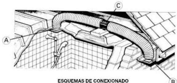
INSTALLATIE AAN BUIZEN
INSTALLATION IN THE PIPING
For installation of the extractor in the air conduit piping, an opening (A) has to be made in the piping where there is the outlet for the extractor connection cables.
The opening must be long enough so that there is no interference with the cables emerging.
The width of the opening will be equal to or greater than the diameter of the drilling cover trim.
To fix the piping to the extractor, use the clamp flanges (C).
A) This tubular extractor is designed to be installed in a flexible or rigid conduit of 100 mm. diameter for the MT-100 and 125 mm diameter for the MT-125.
B) The distance between the intake and exhaust openings should not be more than 3 m.
C) The extractor (C) is placed between points A and B (intake and exhaust) and fixed to the conduits by clamps that hold it securely in position.
D) It should be placed so that the arrows indicating the direction of the air flow coincide with the direction of intake and exhaust.
MT-100 AND MT-125 WITH SUPPORT BRACKET
The extractor (C) is placed between points A and B (intake and exhaust) and fixed in position using the plugs and screws provided.
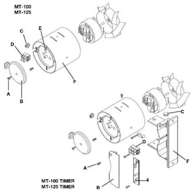
Fig. 1
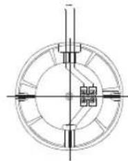
natural_image
Pure technical diagram of a circular mechanical component with centerlines and mounting holes (no text or symbols)MT-100 MT-125
MT-100 TIMER
MT-125 TIMER
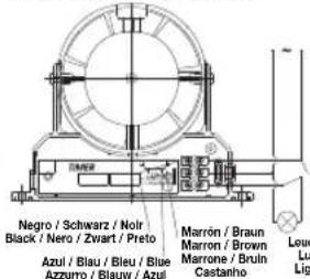
Luces u otra carga
chten oder andere ladung
mières et autre charge
hts or other connection
Luci o altra carica
of andersoortige belasting
luzes ou outra carga
ELECTRICAL CONNECTION MT-100 AND MT-125 WITH SUPPORT BRACKET
The extractor unit should be connected to a single phase supply network at the voltage and frequency indicated on the extractor characteristics plate.
The electrical installation must be fitted with a single-pole switch with a distance between contacts of at least 3 mm.
The unit should be connected to the power supply network before being installed in the conduit (MT-100 and MT-125).
1) Loosen the screw (A) and remove the cover (B).
2) Perforate the plug (C) and thread the power cables through the hole.
3) Connect the power cables to the terminals fo the connection strip (D) and, once connected fix it firmly between the pivots (E).
4) Insert the plug (C) in the hole between the housing (F) and the cover (B).
5) Replace the cover (B) and fix it in place using the screw (A).
The appliance must be permanently connected to a fixed installation of tubing and power supply cable. (Rigid cable with two conductors of at least 1 mm² section. It does not require an earth connection as the unit has double insulation).