Alpha 2 - Air-conditioner Möhlenhoff - Free user manual and instructions
Find the device manual for free Alpha 2 Möhlenhoff in PDF.


User questions about Alpha 2 Möhlenhoff
0 question about this device. Answer the ones you know or ask your own.
Ask a new question about this device
Download the instructions for your Air-conditioner in PDF format for free! Find your manual Alpha 2 - Möhlenhoff and take your electronic device back in hand. On this page are published all the documents necessary for the use of your device. Alpha 2 by Möhlenhoff.
USER MANUAL Alpha 2 Möhlenhoff
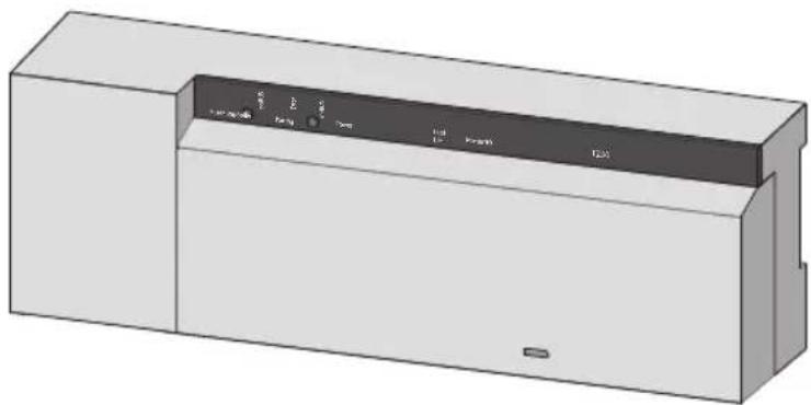
BSF 20x02-xx - 230 V
BSF 40x12-xx - 24 V
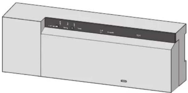
natural_image
3D rendering of a rectangular electronic device with internal control panel (no visible text or symbols)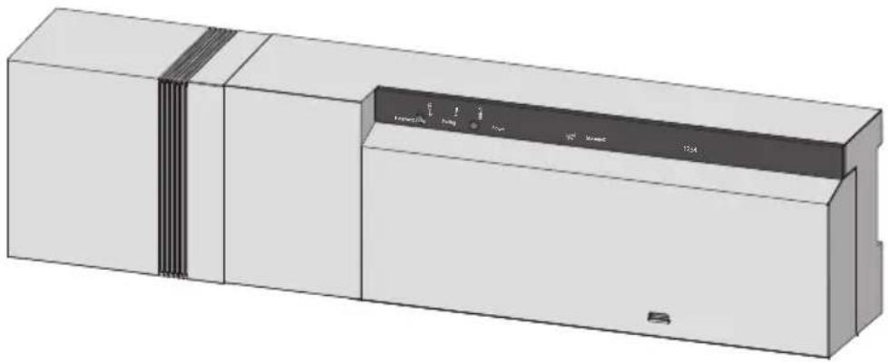
natural_image
3D rendering of a rectangular industrial device with internal components and mounting holes (no visible text or symbols)MAC
Inhalt
1 Sicherheit....3
text_image
1 x (nur BSF 40x12-xx) 1 x* MMS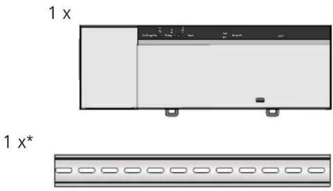
text_image
1 x 1 x** optional
text_image
230 V N L pump boiler ECO CO H %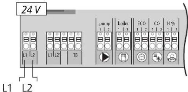
text_image
24 V L1 L2 L1 L2' TB pump boiler ECO CO H % 1 2 1 2 1 2 1 2 1 2 L1 L2
flowchart
graph TD
    A["pump 1 2"] --> B["boiler 1 2"]
    B --> C["ECO 1 2"]
    C --> D["CO 1 2"]
    D --> E["H % 1 2"]
    E --> F["HZ 1 2"]
    F --> G["230 V"]
    F --> H["24 V"]
    I["Kühlen"] --> J["Heizen"]
    J --> K["N"]
    J --> L["L"]
text_image
T2A 24 V L1 L2 L1' L2' TB pump boiler ECO 1 Nnatural_image
Diagram showing a screwdriver pressing down on a wall-mounted device (no text or symbols present)
natural_image
Interior view of an industrial control room with shelving units and a large cylindrical device (no visible text or symbols)
natural_image
Diagram showing a mechanical component with a housing and a cylindrical shaft, both rotating around it (no text or symbols present)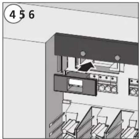
natural_image
Interior view of a file cabinet with filing cabinets and storage compartments (no visible text or symbols)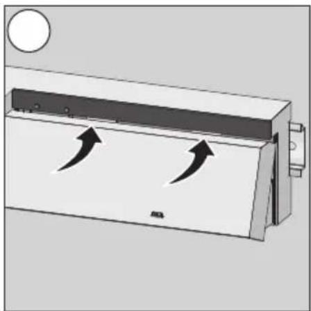
natural_image
Diagram of a refrigerant air duct system with airflow arrows indicating movement (no text or symbols)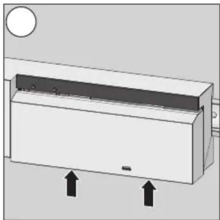
natural_image
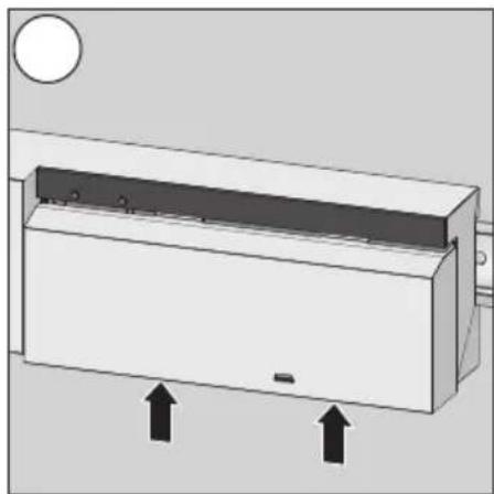
Diagram of a rectangular device with two upward arrows indicating motion or force, no text or symbols present.6.3 Reinigung
natural_image
3D rendering of a white rectangular electronic device with a black control panel on top (no visible text or symbols)
natural_image
3D rendering of a rectangular industrial device with internal components and mounting brackets (no visible text or symbols)Contents
1 Safety 23
1.1 Used signal words and notes....23
1.2 Intended use....23
1.3 General safety notes 23
1.4 Personnel-related preconditions 24
1.5 Limitations for the operation....24
1.6 Conformity....24
2 Versions....25
2.1 Scope of supply....25
2.2 Indications and operating elements....25
2.3 Connections....26
2.4 Technical data 27
3 Installation....28
3.1 Assembly....28
3.2 Electric connection....28
3.2.1 External change-over signal....29
3.2.3 Pump/boiler 24 V 29
3.2.2 Pump/boiler 230 V 29
3.2.4 Optional humidity sensor....29
3.2.5 Pilot function for change-over heating/cooling 30
3.2.6 External timer....30
3.2.8 Use of a safety temperature limiter....31
3.2.9 Connection of Ethernet variants 31
4 Commissioning 32
4.1 First commissioning....32
4.2 Connecting (pairing) / separating base stations....32
4.2 Connecting (pairing) / separating base stations (continued) 33
4.3 Allocation of a room control unit to a heating zone (pairing)....33
4.4 Performing the radio test 33
4.5 System configuration....34
4.5.1 System configuration with microSD card 34
4.5.2 Configuration with room control unit Wireless Display 34
4.6 Resetting the factory settings 36
5 Protection functions and emergency operation ....37
5.1 Protection functions....37
5.1.1 Pump protection function....37
5.1.2 Valve protection function 37
5.1.3 Antifreeze protection function....37
5.1.4 Dew point monitoring....37
5.1.5 Safety temperature limiter 37
5.2 Emergency operation 37
6 Troubleshooting and cleaning....38
6.1 Error indication and elimination of errors 38
6.2 Fuse change....39
6.3 Cleaning....39
7 Decommissioning....40
7.1 Decommissioning....40
7.2 Disposal 40
1 Safety
1.1 Used signal words and notes
The following symbols show you, that
an action must be performed.
√ a precondition must be met.

Warning
Electrical voltage! Danger to life!
The shown symbol warns against electrical voltage. Warning notes are highlighted with horizontal lines.
1.2 Intended use
The base stations Radio 24 V and 230 V of the type BSF x0xx02-xx serve
√ for the arrangement of a single room regulation system (readjustment) with a maximum of 12 zones (depending on the type used) for heating and cooling systems,
√ for the connection of a maximum of 18 actuators and 12 room control units (depending on the type used), a pump, a CO signalling unit, a humidity sensor with potential-free contact as well as an external timer,
√ for a fixed installation.
Every other use is considered as not intended; the manufacturer cannot be held liable for this.
Modifications and conversions are expressively forbidden and lead to dangers the manufacturer cannot be held liable for.
1.3 General safety notes

Warning
Electrical voltage! Danger to life!
The base station is live.
➢ Always disconnect from the mains network and secure against unintended activation before opening it.
➢ Disconnect external voltages existing at the pump and the boiler contact and secure against unintended activation.
Emergency
In case of emergency, disconnect the complete single room control system.

Retain this manual and provide it to future owners.
1.4 Personnel-related preconditions
Authorised specialists
The electrical installations must be performed according to the current VDE regulations as well as according to the regulations of your local electric power utility company. These instructions require special knowledge corresponding to an officially acknowledged degree in one of the following professions:
√ Electrical Equipment Installer or Electronics Engineer
according to the profession designations officially announced in the Federal Republic of Germany, as well as according to comparable professions within the European Community Law.
1.5 Limitations for the operation
This unit is not intended to be used by people (including children) with restricted physical, sensory or mental skills or who lack experience or knowledge, except if they are supervised by a person responsible for their safety or have received instructions on how to use this unit.
Children must be monitored in order to ensure that they do not play with the device.
1.6 Conformity
This product is labelled with the CE Marking and thus is in compliance with the requirements from the guidelines:
√ 2004/108/EG with amendments “Council Directive on the approximation of the laws of the Member States relating to Electromagnetic Compatibility”
√ 2006/95/EG with amendments “Council for Coordination of the Regulations of EU Member Countries regarding the electrical equipment for use within certain voltage limits”
√ "Radio and Telecommunications Terminal Equipment Act (FTEG) and Guideline 1999/5/EG (R&TTE)"
Increased protection requirements may exist for the overall installation, the compliance of which is the responsibility of the installer.
2 Versions
2.1 Scope of supply
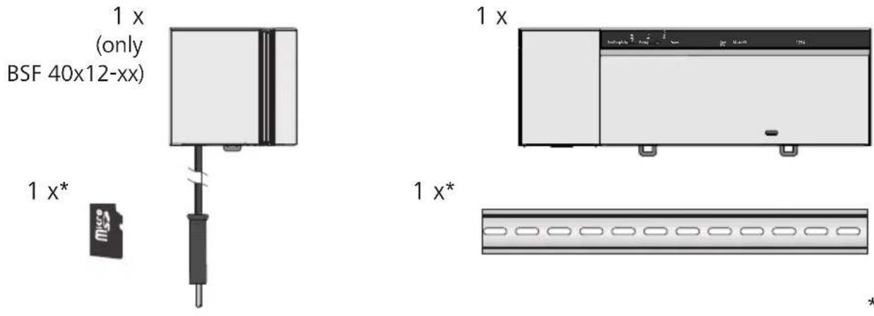
* optional
2.2 Indications and operating elements
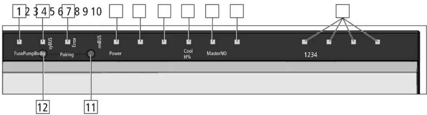
flowchart
graph TD
    A["1 2 3 4 5 6 7 8 9 10"] --> B["FusePumpBoiler"]
    B --> C["syBUS"]
    C --> D["Error"]
    D --> E["mBUS"]
    E --> F["Power"]
    F --> G["Cool H%"]
    G --> H["MasterNO"]
    H --> I["1234"]
    I --> J["Terminal Node"]
    K["12"] --> L["11"]
    M["11"] --> N["12"]
| No. | Designation | LED | Function |
| 1 | Fuse | red | Lights up when fuse has blown |
| 2 | syBUS | yellow | Shows syBUS activity, flashes during writing access on microSD card |
| 3 | Error | red | Lighting up: Safety temperature limiter active |
| 4 | Power | green | Lighting up: Base station ready for operation. |
| 5 | Pump | green | Lighting up: Pump control active |
| 6 | Boiler | green | Lights up when boiler control is active if the boiler relay is used for boiler control. |
| 7 | Cool H% | blue | Lighting up: Cooling operation active.Flashing: Condensation detected. |
| 8 | Master | yellow | Lighting up: Base station is defined as masterFlashing: Base station is defined as slave |
| 9 | NO | yellow | Lighting up: Installation is parameterised for NO actuators (normally open). |
| 10 | Heating zones 1 - x | green | Shows the respective activity of the heating/cooling zones. |
| 11 | rmBUS pushbutton | - | Push-button for the rmBUS functionality |
| 12 | syBUS pushbutton | - | Push-button for the syBUS functionality |
2.3 Connections

text_image
24 V 230 V T2A L1 L2 L1' L2' TB 1 2 3 4 5 6 7 8 9 10 11 12 pump boiler ECO CO H % System BUS HZ 1 HZ 2 HZ 3 HZ 4 1 2 1 2 1 2 1 2 1 2 13 14 15 16 17| No. | Connections Function | |
| 1 | Mains transformer Only | 24 V version: Connection for system transformer |
| 2 | Output 24 V Only 24 V | version: Output for the supply of e. g. a safety temperature limiter (to be provided by the customer) |
| 3/7 | Temperature limiter Con | nections for temperature limiter for the protection of sensitive surfaces, to be provided by the customer (optional) |
| 4 | Protective conductor 1 and 2 | Only 230 V version: Protective conductor connections |
| 5 | Mains connection N/L | Only 230 V version: Connection for mains supply |
| 6 | Output 230 V Only 230 | V version: Optional assignment for a direct energy supply of the pump |
| 8 | Pump Pump activation connection | |
| 9 | Boiler Boiler control connection, or output for CO pilot function | |
| 10 | ECO Potential-free input for the connection of an external timer | |
| 11 | Change over Potential-free input (according to SELV) for an external change-over signal | |
| 12 | Dew point sensor Potential-free input (according to SELV) for dew point sensor | |
| 13 | SYBUS Connects several base stations in order to exchange global system parameters | |
| 14 | Actuators 6 to 18 connections for thermal actuators | |
| 15 | RJ45 connection (optional) | Ethernet interface for the Integration of the base station into the home network |
| 16 | RJ12 connection Connection for active antenna | |
| 17 | microSD card slot Allows the introduction of firmware updates and individual system settings. |
| BSF20102-04 | BSF20202-04 | BSF20102-08 | BSF20202-08 | BSF20102-12 | BSF20202-12 | BSF40112-04 | BSF40212-04 | BSF40112-08 | BSF40212-08 | BSF40112-12 | BSF40212-12 | |
| Ethernet - x - x - x - x - x - x | ||||||||||||
| Number of heating zones | 4 8 12 4 8 12 | |||||||||||
| Number of actuators | 2x2 + 2x1 4x2 + 4x1 6x2 + 6x1 2x2 + 2x1 4x2 + 4x1 6x2 + 6x1 | |||||||||||
| Max. nominal load of all actuators | 24 W | |||||||||||
| Switching power per heating zone | max. 1 A | |||||||||||
| Operating voltage 230 V / ±15% / 50 Hz 24 V / ±20% / 50 Hz | ||||||||||||
| Mains connection NYM connection terminals 3 x 1.5 mm2 System transformer with mains plug | ||||||||||||
| Power consumption (without pump) | 50 W 50 W (limited by the system transformer) | |||||||||||
| Power consumption in idle operation/with transformer | 1.5 W / - 2.4 W / - 1.5 W / - 2.4 W / - 1.5 W / - 2.4 W / - | 0.3 W /0.6 W | 1.1 W /1.4 W | 0.3 W /0.6 W | 1.1 W /1.4 W | 0.3 W /0.6 W | 1.1 W /1.4 W | |||||
| Protection class II | ||||||||||||
| Protection degree/ overvoltage category | IP20 / III | |||||||||||
| Fuse | 5 x 20 mm, T4AH | 5 x 20 mm, T2A | ||||||||||
| Environment temperature | 0 °C – 60 °C | |||||||||||
| Storage temperature | -25 °C to +70 °C | |||||||||||
| Humidity | 5 to 80%, not condensing | |||||||||||
| Dimensions | 225 x 52 x 75 mm | 290 x 52 x 75 mm | 355x 52 x 75 mm | 305 x 52 x 75 mm | 370 x 52 x 75 mm | 435 x 52 x 75 mm | ||||||
| Material | PC+ABS | |||||||||||
| Controlling precision of the target value: | ±1 K | |||||||||||
| Hunting | ±0.2 K | |||||||||||
| Modulation | FSK | |||||||||||
| Carrier frequency | 868 MHz, bidirectional | |||||||||||
| Coverage | 25 m in buildings / 250 m in open air | |||||||||||
| Radiated power | max. 10 mW | |||||||||||
DEU
ENG
FRA
NDL
ITA
ESP
3 Installation
3.1 Assembly

Warning
Electrical voltage! Danger to life!
All installation work must be performed under the absence of voltage.
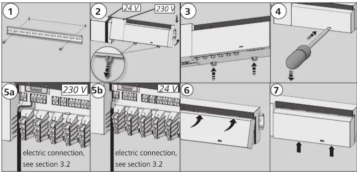
3.2 Electric connection

Warning
Electrical voltage! Danger to life!
All installation work must be performed under the absence of voltage.
The wiring of a single room control system depends on several factors and must be planned and carried through carefully by the installer.
The following cross-sections are applicable for the plug-in/clamping connections:
√ solid wire: 0.5 – 1.5 mm ^4
√ flexible wire: 1.0 – 1.5 mm ^4
√ 8 - 9 mm insulation stripped off the wire
√ The wires of the actuators can be used with factory-mounted end sleeves.
Note: For the 230 V variant, voltage can be supplied via one of the two N and L terminal pairs.
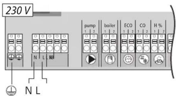
text_image
230 V N L NB pump 1 2 boiler 1 2 ECO 1 2 CO 1 2 H % 1 2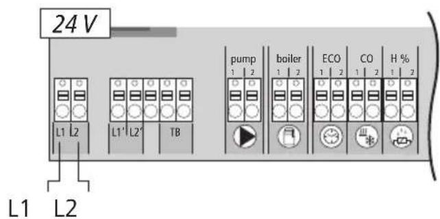
text_image
24 V L1 L2 L1' L2' TB L1 L2 pump boiler ECO CO H % 1 2 1 2 1 2 1 2 1 2 1 2 1 2 1 2 1 2 1 2 1 2 1 2 1 2 1 2 1 2 1 2 1 2 1 2 1 2 1 2 1 2 1 2 1 2 1 2 1 2 1 2 1 2 1 2 1 23.2.1 External change-over signal
flowchart
graph TD
    A["230 V"] --> B["pump"]
    A --> C["boiler"]
    A --> D["ECO"]
    A --> E["CO"]
    A --> F["H %"]
    G["24 V"] --> H["1 L"]
    G --> I["2 L"]
    G --> J["TB"]
    K["Cooling"] --> L["Heating"]
    M["N"] --> N["L"]
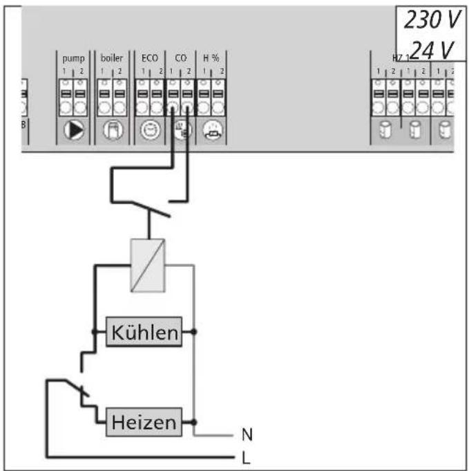
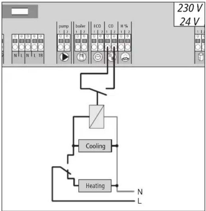
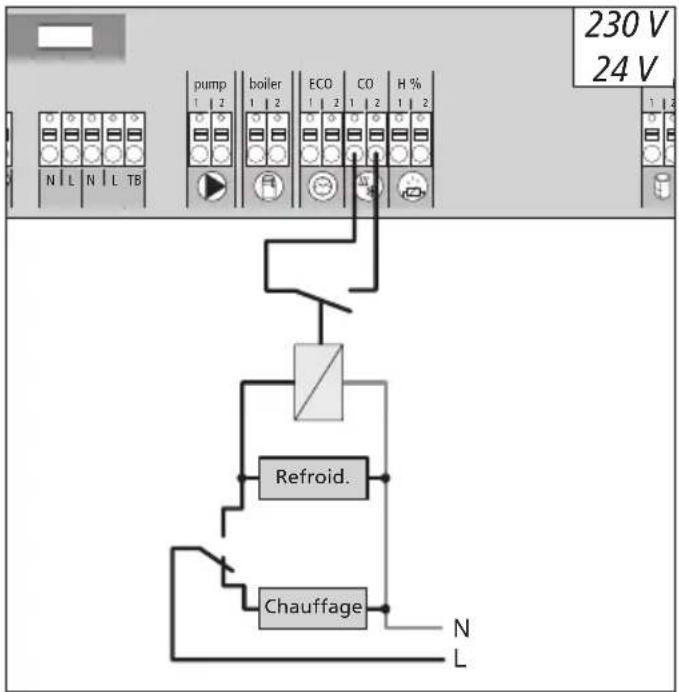
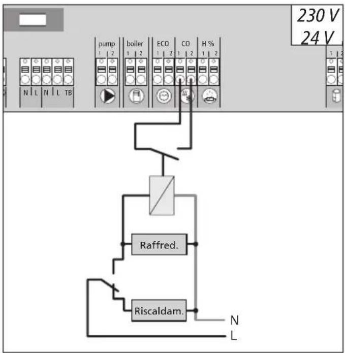
If an external change-over signal is used, the overall installation switches accordingly between heating and cooling.
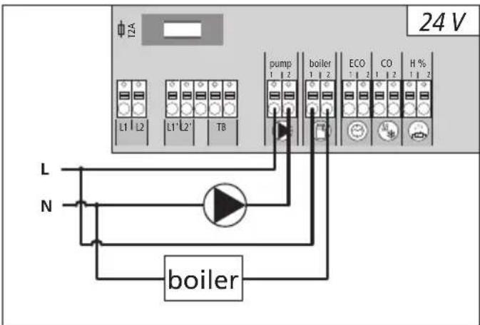
3.2.3 Pump/boiler 24 V
text_image
24 V TZA L1 L2 L1' L2' TB pump boiler ECO CO H % 1 2 1 2 1 2 1 2 L N boilerThe boiler connection allows the control of a heat generator. Additionally, a pump can be supplied and controlled directly.
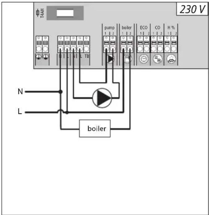
3.2.2 Pump/boiler 230 V
text_image
T4AH 230 V N L TB pump boiler ECO CO H % 1 2 1 2 1 2 1 2 1 2 boilerThe boiler connection allows the control of a heat generator. Additionally, a pump can be controlled directly.
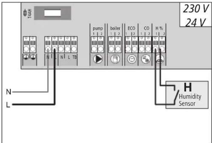
3.2.4 Optional humidity sensor
text_image
T4AH 230 V 24 V N L N L TB pump boiler ECO CO H % 1 2 1 2 1 2 1 2 1 2 H Humidity Sensor LHumidity sensors (to be provided by the customer) serve for dewing protection in the cooling mode.
3.2.5 Pilot function for change-over heating/cooling
text_image
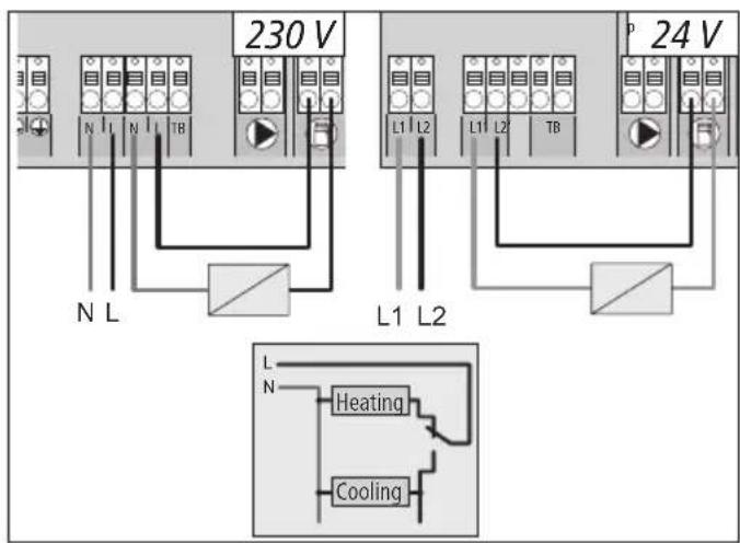
230 V 24 V N L L1 L2 L1 L2 TB L1 L2 L1 L2 L1 L2 L1 L2 L1 L2 L1 L2 Heating CoolingIf no external change-over signal is available, the internal pilot function of the base station can be used for switching the overall installation between the operating modes Heating and Cooling. A relay used by the base station for switching over is used for this.
3.2.6 External timer
text_image
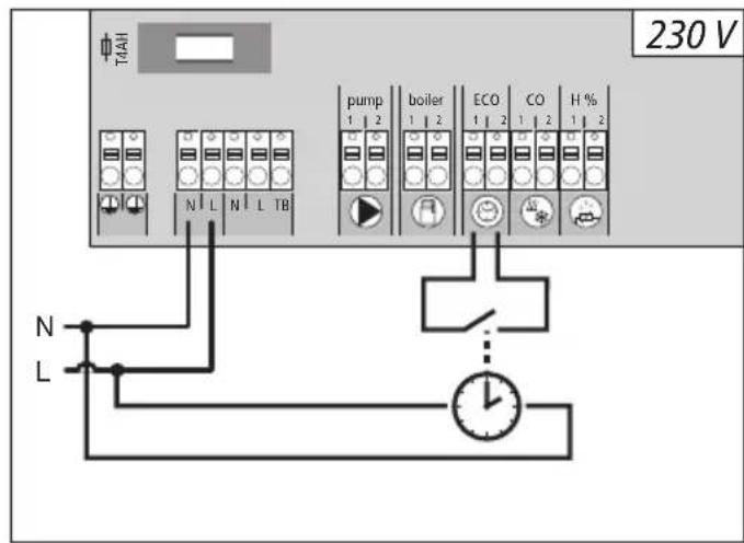
ΦT/AH 230 V N L N L TB pump boiler ECO CO H % 1 2 1 2 1 2 1 2 1 2 N L TB N LThe base station is equipped with an ECO input for connecting an external timer, if the internal clock of the room control unit Radio Display shall not be used. When the input is activated by the timer, the heating zones are switched to night operation.
3.2.7 System BUS
text_image
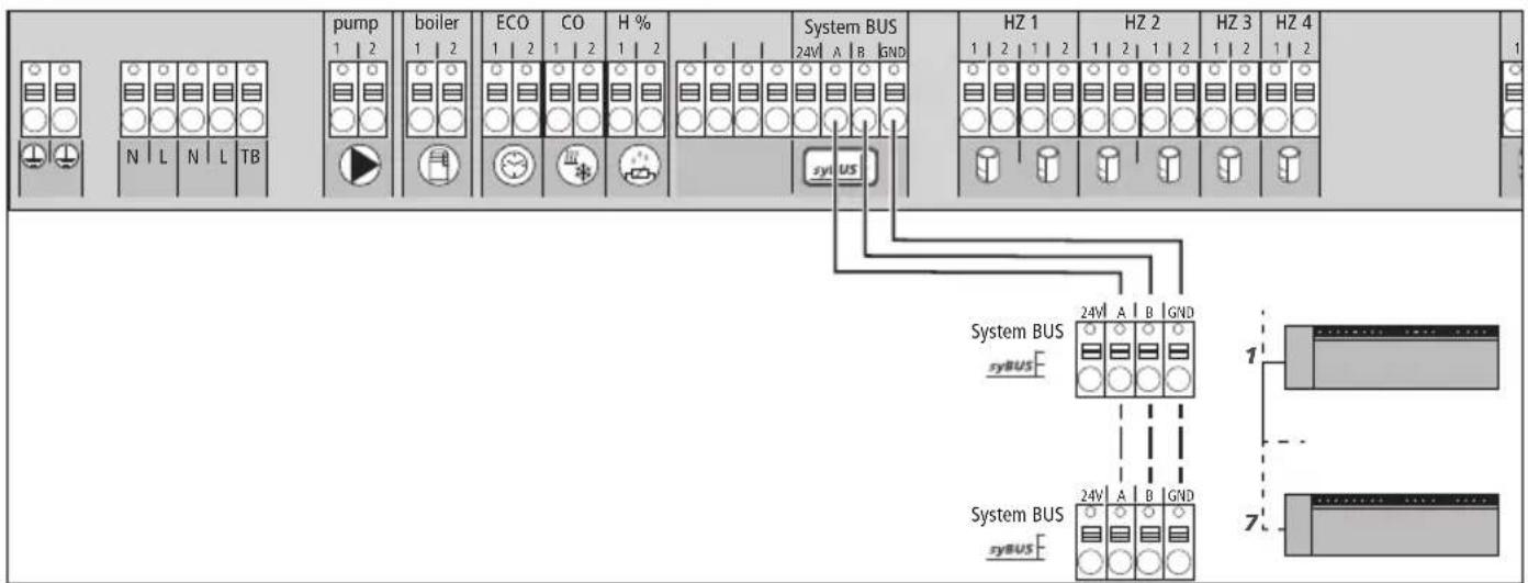
pump 1 2 boiler 1 2 ECO 1 2 CO 1 2 H % System BUS 24V A B GND HZ 1 1 2 1 2 HZ 2 1 2 1 2 HZ 3 1 2 1 2 HZ 4 1 N L N L TB System BUS syBUS 24V A B GND System BUS syBUS 24V A B GND 1 7A maximum of seven base stations can be interconnected via the system BUS (syBUS) in order to exchange global system parameters. After completing the wiring, the base stations must be paired – see section 4.2 For a line diameter <6 mm, a strain relief must be provided by the customer.
Note! The base stations can also be connected via radio, see section 4.2. A mix of both variants is possible.
3.2.8 Use of a safety temperature limiter
text_image
T4AH 230 V N L T3 pump boiler ECO CO H % 1 1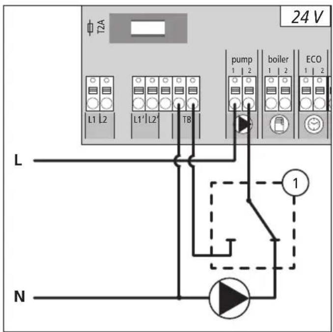
text_image
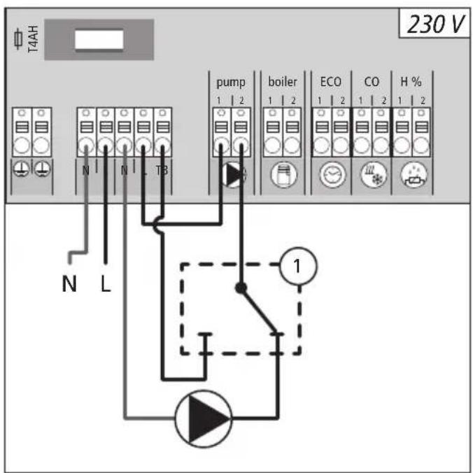
T2A 24 V L1 L2 L1' L2' TB pump boiler ECO 1 NConnection of a customer-supplied safety temperature limiter (1). This device switches off the pump and sets the input to TL if too high flow temperatures for the floor heating are detected. If the TL input is switched, the base station shuts down all actuators automatically.
3.2.9 Connection of Ethernet variants
The base stations BSF xx2xx-xx are equipped with a RJ45 interface and an integrated web server for the control and the configuration of the system via PC/laptop and over the Internet.
Integration of the base station into the network via network cable, or direct connection to PV/laptop
Set-up in the home network
Open the router menu (see manual of the respective device) via the address bar in the web browser (Internet Explorer, Firefox, ...).
Open an overview of all devices in the network.
Compare to the MAC address (see type sign) in order to find out the IP address allocated to the base station.
Note the IP address of the base station and enter it into the address bar of the web browser in order to open the web interface.
Direct connection to PC/laptop:
Open the network settings in the PC/laptop and assign the IP address 192.168.100.1 as well as the subnet mask 255.255.0.0 manually to the PC.
Access to the web interface can be gained by entering the IP address 192.168.100.100 in the address bar of your web browser.
You can find further information on the set-up as well on worldwide access via the Internet under www.ezr-home.de.
4 Commissioning
4.1 First commissioning
The base station is in installation mode during the first 30 minutes after switching on the mains voltage. The target and actual temperatures are compared in this mode, all other functions are deactivated. If the actual temperature is below the target temperature, the output allocated to the respective room control unit is activated at the base station. This allows signalling at the base station without delay, enabling the control of the allocation between the room control unit and the output of the base station.
▶ Switch on the mains voltage.
√ The base station initialises the installation mode for 30 minutes.
√ If the base station is parameterised for NC actuators, all heating zones are activated for 10 minutes in order to unlock the first-open function of the NC actuators.
√ The power LED (operation display) lights up continuously.
4.2 Connecting (pairing) / separating base stations
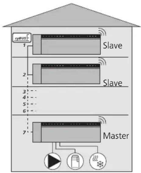
If several base stations are used in one heating system, a maximum of seven units can be coupled (paired) for the exchange of global system parameters via radio or system bus (syBUS). The radio range of the base station must be observed for the radio connection. If the radio range is insufficient, pairing must be performed with the syBUS. Communication is done according to the master/slave principle. Requirements and status messages are exchanged between the units. The master unit centrally controls the directly connected functions/components:
• CO input/output
(if the pilot function is activated)
- Boiler output
- Pump output
flowchart
graph TD
    A["Master"] --> B["Slave"]
    B --> C["SyBUS"]
    C --> D["1"]
    D --> E["2"]
    E --> F["3"]
    F --> G["4"]
    G --> H["5"]
    H --> I["6"]
    I --> J["7"]
    J --> K["Master"]
    style A fill:#f9f,stroke:#333
    style K fill:#ccf,stroke:#333
Note: The base station the components are connected to must be configured as master. Further base stations can only be paired with the master.
The pairing of base stations is done as follows:
➢ Press the syBUS button of the base station to be configured as master for three seconds in order to start the pairing mode.
√ The LED "syBUS" flashes.
√ For three minutes, the pairing mode is ready to receive the pairing signal of another room control unit.
➢ Press the syBUS button of the base station to be configured as slave two times consecutively for one second, in order pair it with the master.
√ The paring mode ends automatically after the process has finished.
√ The LED "Master" lights up permanently at the master base station.
√ The LED "Master" flashes if the base station has been configured as slave.
Repeat the process for paring another base station.
4.2 Connecting (pairing) / separating base stations (continued)
The separation of paired base stations can be performed as follows:
➢ Press the syBUS button of the base station to be separated for three seconds in order to start the pairing mode.
√ The LED "syBUS" flashes.
➢ Press the syBUS pushbutton again for a duration of 10 seconds.
√ The base station restarts and the LED "Master" goes out.
4.3 Allocation of a room control unit to a heating zone (pairing)
➢ Press the rmBUS button of the base station for three seconds in order to start the pairing mode.
√ The LED "Heating zone1" flashes.
Select the desired heating zone by pressing shortly again.
√ For three minutes, the selected heating zone is ready to receive the pairing signal of a room control unit.
➢ Activate the pairing function at the room control unit (see Room Control Unit Manual).
√ The pairing mode is left after establishing a successful allocation.
√ The LED of the heating zone previously selected will light up for 1 minute.
Repeat the process for allocating more room control units.
Tip One Room Control Unit can be allocated to various heating zones.
The allocation of several room control units to one zone is impossible.
4.4 Performing the radio test
The radio test allows to verify the communication between the base station and the room control unit. The radio test must always be carried through at the planned installation location of the room control unit.
√ The base station must not be in pairing mode for this.
➢ Start the radio test at the room control unit (see Room Control Unit Manual).
√ The heating zone allocated to the room control unit is activated for one minute, thus it is switched off or on depending on the status of operation.
√ If there is no activation, the reception conditions are unfavourable. Proceed as follows:
➢ Taking into account the installation conditions of the room control unit, change the installation position until you have a reception signal, or
Use the optional accessories "Active antenna" or "Repeater" in order to amplify the radio signal. You can find information on the installation in the respective manual.
4.5 System configuration
The configuration of the base station is done optionally via the microSD, the software interface of the Ethernet variant or the Service level of the room control unit Bus Display.
4.5.1 System configuration with microSD card
Individual settings can be made via the EZR Manager SD Card under www.ezr-home.de and transferred to the base station via the microSD card. As of software version 01.70, the base station accepts microSD cards >2 GB in the formats FAT16 or FAT32.
Open www.ezr-home.de in the web browser of your PC, select EZR Manager SD Card and follow the instructions on-line.
Insert the microSD card with the updated data into the base station.
√ The transfer process will start automatically and copy the updated data into the base station.
√ The LED "syBUS" flashes during the transfer process.
√ After a successful data transmission, the LED "syBUS" goes out.
4.5.2 Configuration with room control unit Wireless Display
The Service level of the base station Wireless Display is protected with a PIN code and may only be used by authorized specialists.
Attention! Faulty configuration leads to errors and damage to installations.
▶ Press the rotary control.
Select the menu "Service Level" and activate by pressing.
➢ Enter the 4-digit PIN (standard: 1234) by rotating and pressing.
➢ Select parameters (PAr) by pressing again and enter the number code of the desired parameter (see following table).
➢ Change parameters as required and confirm by pressing.
| No. | Parameters Description Unit | ||
| 010 | Used heating system Adjustable per | heating zone: Floor heating (FBH) standard / FBH low energy / radiator / convector passive / convector active | FBH St.=0FBH NE=1RAD=2KON pas.=3KON act.=4 |
| 020 | Heating/cooling block Blocking the | switching outputs depending on the activated operating mode (heating/cooling) | normal=0Heating block=1Cooling block=2 |
| 030 | Operation lock (child safety lock) | Unlocking the operating lock with password protection Deactivated=0Activated=1 | |
| 031 | Operating lock password Determine | PIN if parameter 30 is set to active 0000..9999 | |
4.5.2 Configuration with room control unit Wireless Display (continued)
| No. | Parameters Description Unit | ||
| 040 | External sensor connected to the RBG | Logging on an additional sensor for the registration of the floor temperature (FBH), the room temperature or the dew point | no sensor=0Dew point sen.=1Temp FBH=2Temp room=3 |
| 060 | Correction of actual value registration | Registration of the actual temperature with a correction factor | -2.0...+2.0 Kin 0.1 increments |
| 110 | Control direction switching outputs | Switchover of NC and NO actuators (only globally) NC=0 / NO=1 | |
| 115 | Use as setback input Change-over | between use of the ECO input for setback or holiday function of the room control unit.The holiday function cannot be activated any longer via the room control unit if this parameter has been set to 1. | ECO=0Holiday=1 |
| 120 | Unit of temperature display Toggle | function of the display between degree Celsius and degree Fahrenheit | °C=0°F=1 |
| Pump configuration | |||
| 130 | Pump output Use the control of a local recirculation pump (in the heating circuit distributor) or a global recirculation pump (heating installation). | local=0global=1 | |
| 131 | Pump type Selection of the used pump: Conventional Pump (KP) / High efficiency Pump (HP) | CP=0HP=1 | |
| 132 | Pump line-up time Time elapsing from the moment of the command from a switching output until the pump is actually switched on. | [min] | |
| 133 | Pump follow-up time Time elapsing from the moment of switching off the switching outputs until the pump is actually switched off. | [min] | |
| 134 | Control direction switching output | The control direction can be inverted if the pump relay is used as control output | normal=0inverted=1 |
| 135 | Minimum running time The minimum running time indicates how long the HP must run until it may be switched off again. | [min] | |
| 136 | Minimum standstill time High efficiency pump: The pump may only be switched off if a minimum standstill time can be ensured. | [min] | |
| Configuration of change-over functionality / boiler relay | |||
| 140 | Function of relay boiler / CO output | Selection whether the switching output shall serve for controlling a pump relay, or as CO pilot | Boiler=0CO pilot=1 |
| 141 | Line-up time Boiler relay line-up time for conventional pump [min] | ||
| 142 | Follow-up time | Boiler relay follow-up time for conventional pump | [min] |
| 143 | Control direction switching outputs | The relay function can be inverted if used as a control output. | normal=0inverted=1 |
| 160 | Antifreeze protection Activation of control outputs for Tactual <x °C Deactivated=0 | Activated=1 | |
| 161 | Antifreeze temperature Antifreeze function limit value [°C] | ||
| 170 | Smart Start Learning-in of the temperature behaviour of the individual heating zones | Deactivated=0Activated=1 | |
4.5.2 Configuration with room control unit Wireless Display (continued)
| No. | Parameters Description Unit | ||
| Emergency operation | |||
| 180 D | Duration until activation Duration | until the activation of the emergency operation routine | [min] |
| 181 P | PWM cycle duration in emergency operation | Duration of a PWM cycle in emergency operation [min] | |
| 182 C | Cycle duration PWM heating Control | duration in heating operation [%] | |
| 183 C | Cycle duration PWM cooling Control | duration in cooling operation [%] | |
| Valve protection function | |||
| 190 D | Duration until activation Starting time | time after last activation [d] | |
| 191 | Valve activation duration | Valve activation duration (0= function deactivated) | [min] |
| Pump protection function | |||
| 200 D | Duration until activation Starting time | time after last activation [d] | |
| 201 | Activation duration | Activation duration (0 = function deactivated) | [min] |
| 210 | First open function (FO) | Activation of all switching outputs at power-up | [min]Off=0 |
| 220 A | Automatic switching between summer and winter time | If the conversion is activated, time adaptation is performed automatically according to CET guidelines | Deactivated=0Activated=1 |
| 230 S | Setback difference temperature | In case of activation of the setback via the external input | [K] |
4.6 Resetting the factory settings
Attention! All user settings will be lost.
If present, remove the microSD Card from the base station and delete the parameter file "params_usr.bin" at the PC.
➢ Press the rmBUS button of the base station Radio for three seconds in order to start the pairing mode.
√ The LED "Heating zone1" flashes.
➢ Press the rmBUS pushbutton again for a duration of 10 seconds.
√ All heating zone LEDs flash simultaneously; after another 5 seconds of pressing the pushbutton they light up simultaneously, and go out after that.
√ Now the base station is reset to factory settings and behaves as it did during the first commissioning (see section 4).
Note! Previously allocated room control units must be paired newly, see section 4.3.
5 Protection functions and emergency operation
5.1 Protection functions
The base station is equipped with many protection functions for avoiding damage to the overall system.
5.1.1 Pump protection function
In order to avoid damage by longer standstill times, the pump is activated within pre-defined periods. The LED “pump” lights up during these periods.
5.1.2 Valve protection function
During periods without valve activation (e. g. outside the heating period) all heating zones with logged-in room control unit are activated in a cyclic way in order to avoid clogging of the valves.
5.1.3 Antifreeze protection function
Independent from the operating mode, every switching output is equipped with an antifreeze function. As soon as a previously set antifreeze temperature (5...10°C) is fallen short of, the valves of the allocated heating zone are activated until this temperature is reached. The antifreeze temperature can be set via the microSD card, via the software surface of the Ethernet variant or via the service level of the RBG display (parameter 161).
5.1.4 Dew point monitoring
If the installation is equipped with a dew point sensor (provided by the customer), the valves of all heating zones are closed if dewing is detected in order to avoid damages due to humidity.
The dew point sensor input is only used during cooling operation.
5.1.5 Safety temperature limiter
If an optional safety temperature limiter is used, all valves are closed when a critical temperature is exceeded in order to avoid damage to sensitive floor coverings.
5.2 Emergency operation
If the base station is unable to establish a radio connection to the room control unit allocated to the heating zone after a set time has elapsed, emergency operation is activated automatically. In emergency operation, the switching outputs at the base station are activated with a modified PWM cycle duration (parameter 181) independent from the heating system in order to avoid complete cooling of the rooms (in heating operation) or dewing (in cooling operation).
6 Troubleshooting and cleaning
6.1 Error indication and elimination of errors

text_image
SyBUS Error mBUS FusePumpBoiler Pairing Power Cool H% MasterNO 1234| Signalling of the LEDs Meaning Elimination | ||
Fuse Duration in seconds 01234 Fuse  | Fuse defective | ➢ Change the fuse (see section 6.2) |
Error / Pump Duration in seconds 01234 Pump Error  | Safety temperature limiter active, valves are closed | √ The normal control operation is activated automatically after falling short of the critical temperature |
„Cool H%” (only cooling operation) Duration in seconds Cool  | Dewing detected, valves are closed | √ The normal control operation is activated automatically if no condensation is sensed any more. |
Heating zone Duration in seconds 01234 HZ off HZ on  | Radio connection to the room control unit faulty | ➢ Change the position of the room control unit or use a repeater or an active antenna. |
Heating zone Duration in seconds 01234 HZ off HZ on  | Low battery capacity of the room control unit | ➢ Change the batteries in the room control unit |
Heating zone Duration in seconds 01234 HZ  | Emergency operation active | ➢ Change the batteries in the room control unit➢ Perform a radio test➢ If necessary, reposition the room control unit.➢ Replace a defective room control unit |

LED on LED off
6.2 Fuse change

Warning
Electrical voltage! Danger to life!
The base station is live.
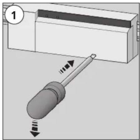
➢ Always disconnect from the mains network and secure against unintended activation before opening the base station.
natural_image
Diagram showing a screwdriver pressing down on a component, with arrows indicating motion (no text or symbols present)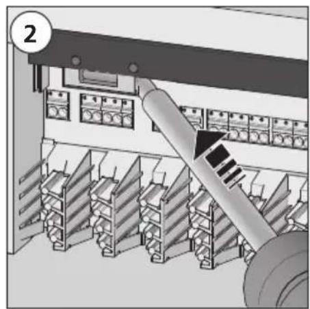
natural_image
Interior view of an industrial control room with shelving units and a conveyor belt (no visible text or symbols)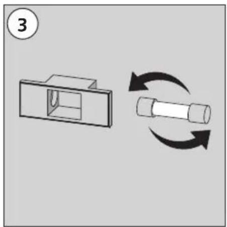
natural_image
Diagram showing a mechanical component with a housing and a rotating shaft, both with curved arrows indicating rotation (no text or symbols present)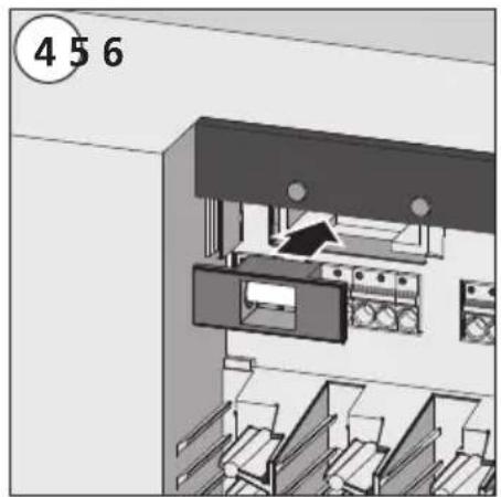
natural_image
Interior view of a file cabinet with filing cabinets and storage racks (no visible text or symbols)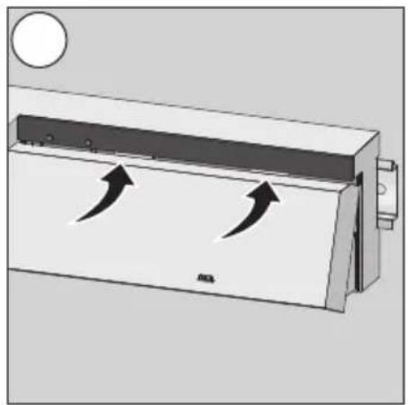
natural_image
Diagram of a rectangular device with two curved arrows indicating flow or movement, no text or symbols present.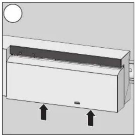
natural_image
Diagram of a rectangular device with two upward arrows indicating direction, no text or symbols present6.3 Cleaning
Only use a dry and solvent-free, soft cloth for cleaning.
7 Decommissioning
7.1 Decommissioning

Warning
Electrical voltage! Danger to life!
The base station is live.
➢ Always disconnect from the mains network and secure against unintended activation before opening it.
➢ Disconnect external voltages existing at the pump and the boiler contact and secure against unintended activation.
➢ Pull the mains plug and and disconnect the entire installation.
Remove the wiring to all externally connected components as e. g. pump, boiler and actuators.
- Uninstall the device and dispose of properly.
7.2 Disposal

The base stations must not be disposed of with domestic waste. The operator has the duty to hand the devices to appropriate collection points. The separate collection and orderly disposal of all materials will help to conserve natural resources and ensure a recycling in a manner that protects human health and the environment. If you need information about collection points for your devices, please contact your local municipality or your local waste disposal services.
Made in Germany


This manual is protected by copyright. All rights reserved. It may not be copied, reproduced, abbreviated or transmitted, neither in whole nor in parts, in any form, neither mechanically nor electronically, without the previous consent of the manufacturer. © 2014
BSF 20x02-xx - 230 V
BSF 40x12-xx - 24 V
natural_image
3D rendering of a rectangular electronic device with internal control panel (no visible text or symbols)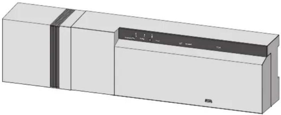
natural_image
3D rendering of a rectangular industrial device with internal components and mounting holes (no visible text or symbols)Table des matières
3 Installation....48
7.1 Mise hors service....60
7.2 Elimination....60
3.2.1 Signal change-over externe
flowchart
graph TD
    A["230 V"] --> B["pump"]
    A --> C["boiler"]
    A --> D["ECO"]
    A --> E["CO"]
    A --> F["H %"]
    B --> G["1 2"]
    C --> H["1 2"]
    D --> I["1 2"]
    E --> J["1 2"]
    F --> K["1 2"]
    G --> L["N L N L TB"]
    H --> M["Refrond."]
    I --> N["Chauffage"]
    J --> N
    K --> N
    L --> N
    M --> N
    N --> O["N L"]
text_image
24 V T2A L1 L2 L1' L2' TB pump boiler ECO 1 Nnatural_image
Diagram showing a screwdriver inserted into a rectangular device with directional arrows indicating motion (no text or symbols present)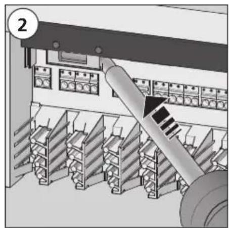
natural_image
Interior view of an industrial control room with shelving units and a conveyor belt (no visible text or symbols)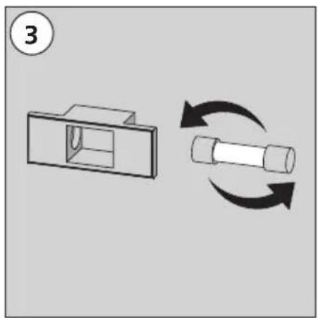
natural_image
Diagram showing a mechanical component with a housing and a rotating shaft, both with curved arrows indicating rotation (no text or symbols present)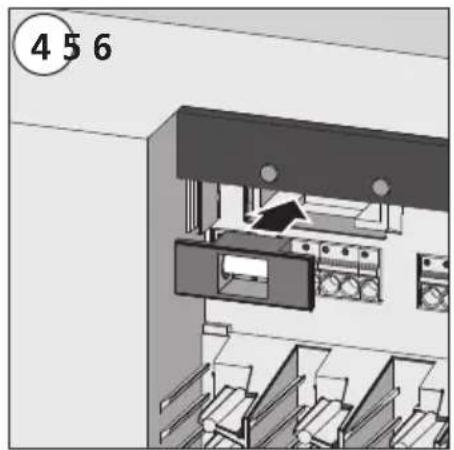
natural_image
Interior view of a room with filing cabinets and storage racks (no visible text or symbols)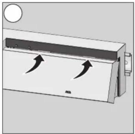
natural_image
Diagram of a rectangular device with two curved arrows indicating flow or movement, no text or symbols present.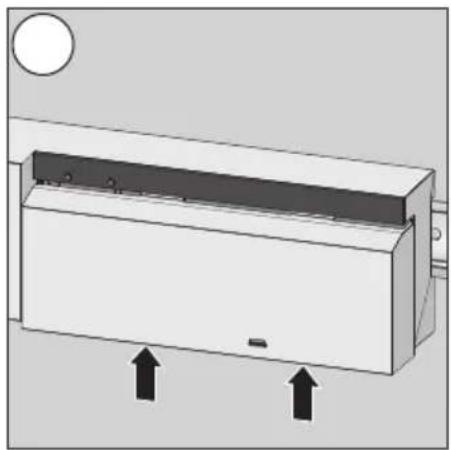
natural_image
Diagram of a rectangular device with two upward arrows indicating direction, no text or symbols present6.3 Nettoyage
natural_image
3D rendering of a white rectangular appliance with internal control panel (no visible text or symbols)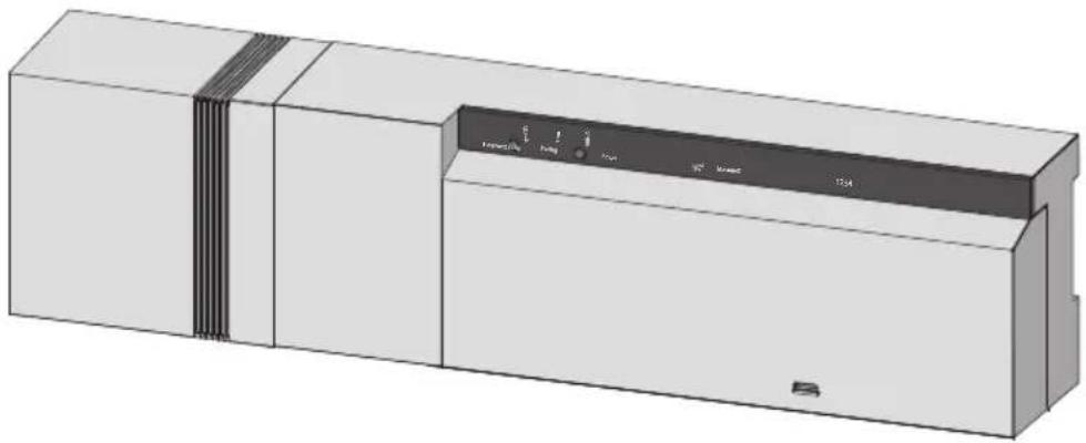
natural_image
3D rendering of a rectangular industrial device with internal components and mounting tabs (no visible text or symbols)DEU
ENG
FRA
NDL
ITA
ESP
Inhoud
1 Veiligheid....63
text_image
24 V L1 L2 L1' L2' TB pump boiler ECO CO H % 1 2 1 2 1 2 1 2 1 2 L1 L2 L1
flowchart
graph TD
    A["230 V"] --> B["pump"]
    A --> C["boiler"]
    A --> D["ECO"]
    A --> E["CO"]
    A --> F["H %"]
    G["24 V"] --> H["1 L"]
    G --> I["N L TB"]
    J["Koelen"] --> K["Switch"]
    K --> L["Verwarm."]
    L --> M["N L"]
text_image
230 V 24 V N L L1 L2 L1 L2 TB L1 L2 L1 L2 L1 L2 L1 L2 Verwarm Koelentext_image
24 V T2A L1 L2 L1' L2' TB pump boiler ECO 1 Nnatural_image
Diagram showing a screwdriver interacting with a rectangular device, with directional arrows indicating motion (no text or symbols present)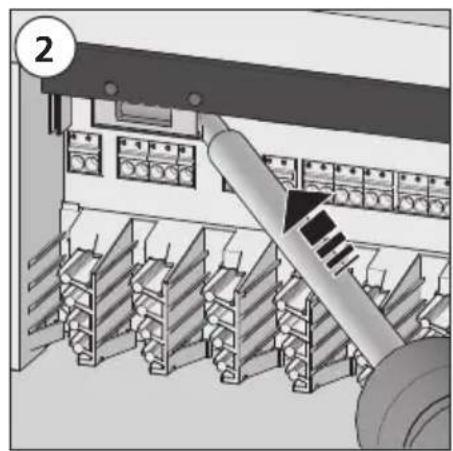
natural_image
Interior view of an industrial control room with shelving units and a mechanical device (no visible text or symbols)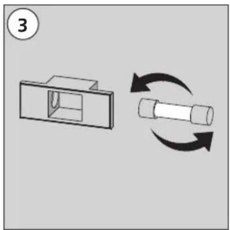
natural_image
Diagram showing a mechanical component with a housing and a cylindrical shaft, both rotating around it (no text or symbols present)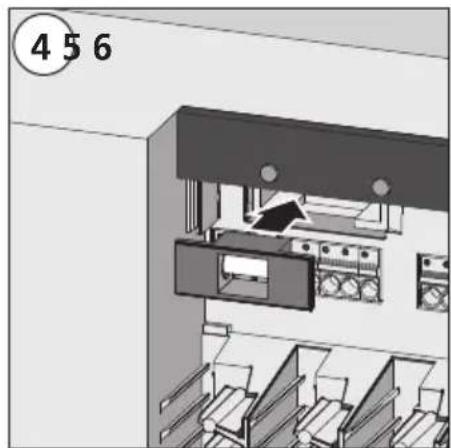
natural_image
Interior view of a cabinet or filing cabinet with drawers and storage compartments (no visible text or symbols)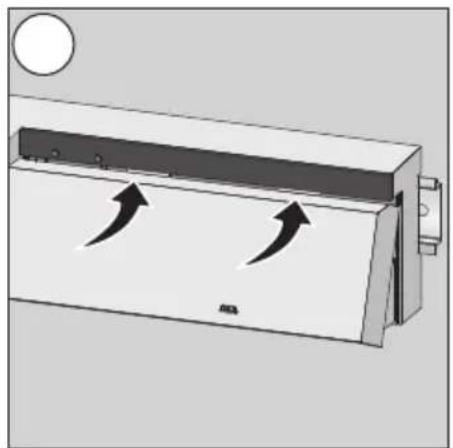
natural_image
Diagram of a refrigerant air duct system with airflow arrows indicating movement (no text or symbols)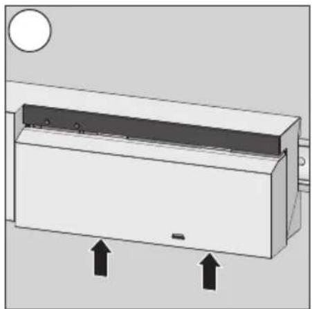
natural_image
Diagram of a rectangular device with two upward arrows indicating direction, no text or symbols present6.3 Reiniging
natural_image
3D rendering of a white rectangular electronic device with a black control panel on top (no visible text or symbols)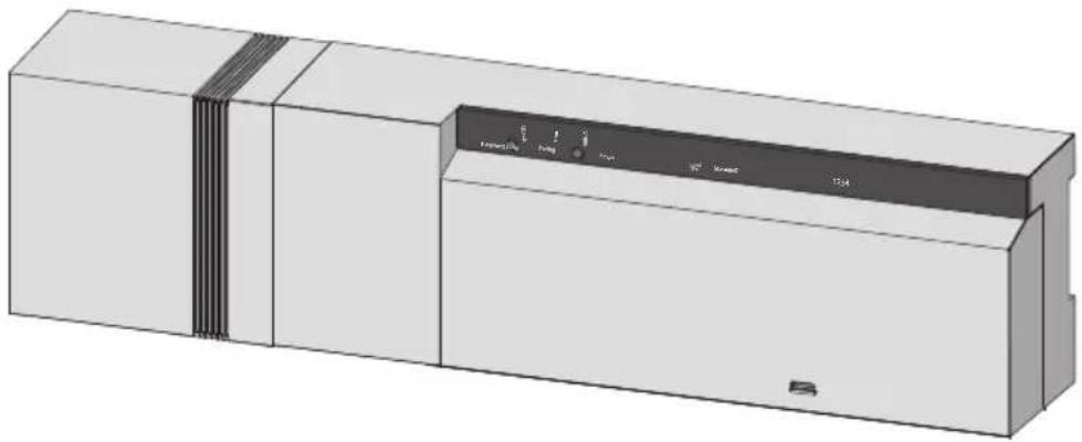
natural_image
3D rendering of a rectangular industrial device with internal components and mounting holes (no visible text or symbols)DEU
ENG
FRA
NDL
ITA
ESP
Sommario
1 Sicurezza....83
text_image
1 x (solo BSF 40x12-xx) 1 x* mags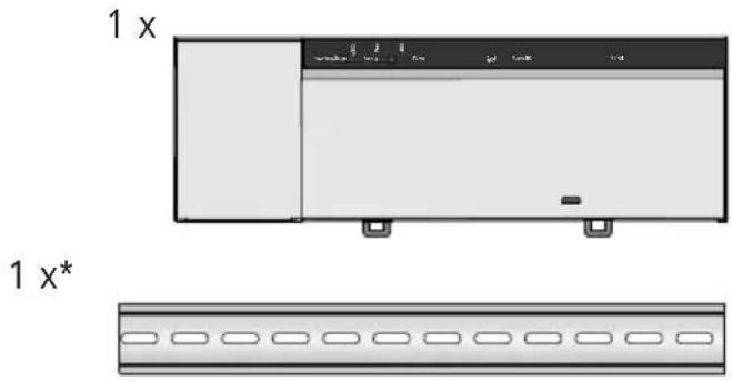
text_image
1 x 1 x* 1 x* opzionale
text_image
230 V N L pump boiler ECO CO H %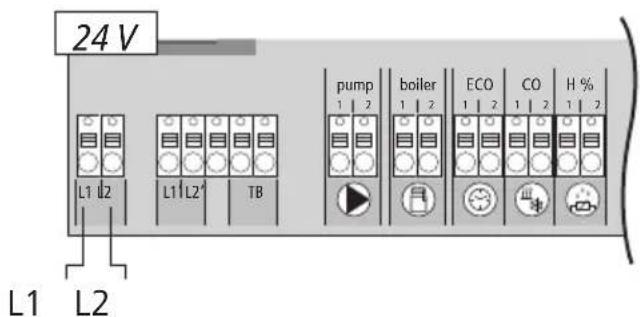
text_image
24 V L1 L2 L1 L2' TB pump boiler ECO CO H % 1 2 1 2 1 2 1 2 1 2 L1 L2 L1 L2' TB3.2.1 Change Over Signal esterno
flowchart
graph TD
    A["230 V"] --> B["pump"]
    A --> C["boiler"]
    A --> D["ECO"]
    A --> E["CO"]
    A --> F["H %"]
    G["24 V"] --> H["1 L"]
    G --> I["N L TB"]
    J["Raffred."] --> K["Riscaldam."]
    K --> L["N L"]
text_image
230 V 24 V N L L1 L2 L1 L2 TB L1 L2 L1 L2 L1 L2 Riscald. Raffredtext_image
T2A 24 V L1 L2 L1' L2' TB pump boiler ECO 1 Nflowchart
graph TD
    subgraph Server Architecture
        A["1"] --> B["Slave"]
        C["2"] --> D["Slave"]
        E["3"] --> F["Master"]
        G["4"] --> F
        H["5"] --> F
        I["6"] --> F
        J["7"] --> F
    end
    style Server Architecture fill:#f9f,stroke:#333
    Note: Nodes 1-7 are labeled; Source: CyBUS; Data Flow: Wi-Fi, Process: Radio, Email, Print, Email icon visible
natural_image
Diagram showing a screwdriver pressing down on a component, with arrows indicating motion (no text or symbols present)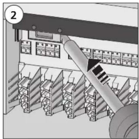
natural_image
Interior view of an industrial control room with shelving units and a conveyor belt (no visible text or symbols)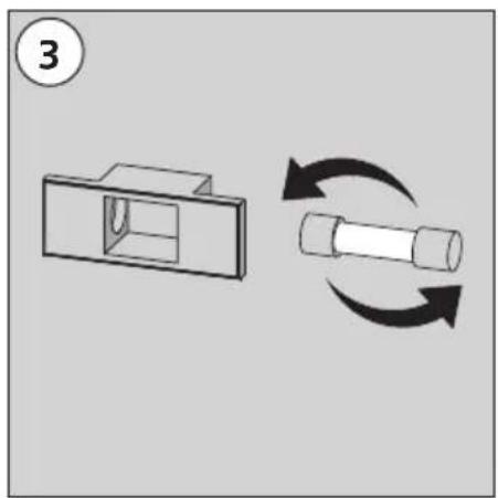
natural_image
Diagram showing a mechanical component with a housing and a cylindrical shaft, both rotating around it (no text or symbols present)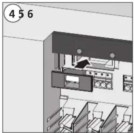
natural_image
Interior view of a file cabinet with filing cabinets and storage racks (no visible text or symbols)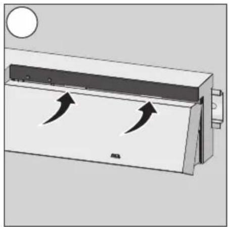
natural_image
Diagram of a rectangular device with two curved arrows indicating flow or movement, no text or symbols present.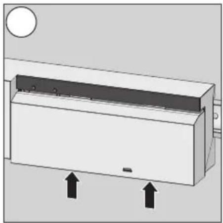
natural_image
Diagram of a rectangular device with two upward arrows indicating direction, no text or symbols present6.3 Pulizia
natural_image
3D rendering of a white rectangular electronic device with a black control panel on top (no visible text or symbols)
natural_image
3D rendering of a rectangular industrial device with internal components and mounting holes (no visible text or symbols)DEU
ENG
FRA
NDL
ITA
ESP
Contenido
1 Seguridad 103
text_image
T2A 24 V L1 L2 L1' L2' TB pump boiler ECO 1 Nnatural_image
Diagram showing a screwdriver pressing down on a component, with arrows indicating motion (no text or symbols present)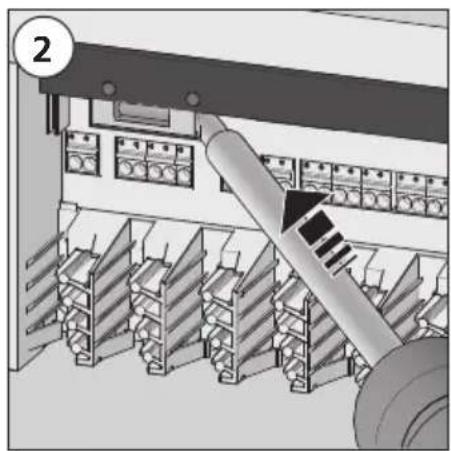
natural_image
Interior view of an industrial control room with shelving units and a large cylindrical device (no visible text or symbols)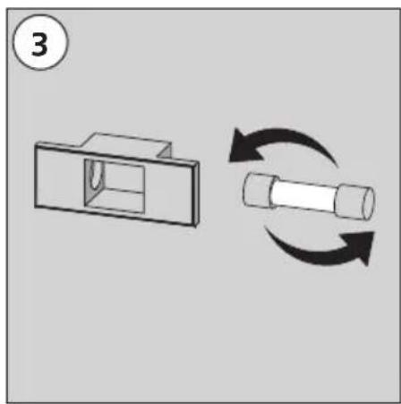
natural_image
Diagram showing a mechanical component with a rectangular housing and a cylindrical shaft, both rotating with curved arrows (no text or symbols)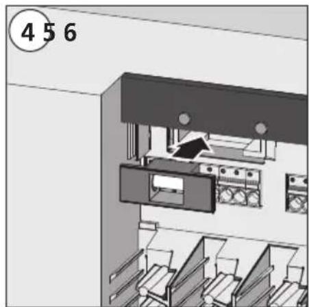
natural_image
Interior view of a cabinet or filing cabinet with multiple drawers and storage compartments (no visible text or symbols)
natural_image
Diagram of a refrigerant air duct system with airflow arrows indicating movement (no text or symbols)