Primo 5.0-1 SC - Air Conditioning Fronius - Free user manual and instructions
Find the device manual for free Primo 5.0-1 SC Fronius in PDF.


User questions about Primo 5.0-1 SC Fronius
0 question about this device. Answer the ones you know or ask your own.
Ask a new question about this device
Download the instructions for your Air Conditioning in PDF format for free! Find your manual Primo 5.0-1 SC - Fronius and take your electronic device back in hand. On this page are published all the documents necessary for the use of your device. Primo 5.0-1 SC by Fronius.
USER MANUAL Primo 5.0-1 SC Fronius
Operating Instructions
Fronius Primo
3.0-1 / 3.5-1 / 3.6-1 / 4.0-1
4.6-1 / 5.0-1 AUS / 5.0-1
5.0-1 SC / 6.0-1 / 8.2-1
EN | Operating Instructions
FR | Instructions de service
natural_image
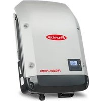
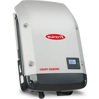
Exterior view of a FRONIUS PRIMO industrial powertrain device (no signage or text beyond branding)Contents
Safety rules.5.
General.5.
Environmental conditions.5.
Qualified personnel 5
Noise emission values.6
EMC measures 6
Disposal 6.
Data protection 6
Copyright 6.
General 8.
Explanation of safety notices 8
Device concept.8
Proper use/intended purpose.9
Warning notices on the device 9.
Data communication and Fronius Solar Net 11
Fronius Solar Net and data interface 11
Data communication area 11
Explanation of the multifunction current interface 12
Description of the "Fronius Solar Net" LED 13
Example 14
Installing option cards in the inverter 14
Dynamic power reduction by means of inverter 15
System monitoring.... 16
General 16
Fronius Datamanager during the night or when the available DC voltage is insufficient.... 16
Starting for the first time 16
Further information on Fronius Datamanager 2.0 18
Controls and indicators 19
Controls and displays.... 19
Display 20
The menu level 21
Activating display backlighting 21
Automatic deactivation of display backlighting / changing to the "NOW" menu item 21
Open menu level 21
The NOW, LOG and GRAPH menu items 22
NOW LOG GRAPH 22
Values displayed in the NOW and LOG menu items 22
SETUP menu item 24
Initial setting 24
SETUP 24
Navigating the SETUP menu item 24
Setting menu entries, general 25
Application example: Setting the time 26
The Setup menu items 28
Standby 28
WiFi Access Point 28
DATCOM 29
USB 29
Relay (floating contact switch) 31
Energy Manager(under Relay menu item) 32
Time / Date 33
Display settings 34
ENERGY YIELD 35
Fan 36
The INFO menu item.... 37
INFO 37
Measured values PSS status Grid status 37
Device information 38
Version 39
Switching the key lock on and off 40
General 40
Switching the key lock on and off 40
USB Stick as a Data Logger and for Updating Inverter Software.41
USB flash drive as a datalogger 41
Suitable USB flash drives 41
USB stick for updating the inverter software.42
Removing the USB flash drive.42
The Basic menu.43
General 43
Access the Basic menu.43
Menu items in the Basic menu 43.
Switching off current supply and restarting the inverter 45.
Switch off power to the inverter.45.
Status diagnostics and troubleshooting 46.
Status code display 46.
Total failure of the display 46
Status codes in the e-Manual 46
Customer service 46
Operation in dusty environments 46
Technical data
General data and protection devices Fronius Primo 3.0-1 - 8.2-1 47
WLAN 50
Explanation of footnotes 51
Integrated DC disconnector 51
Applicable standards and guidelines 52
Warranty terms and conditions, and disposal 53
Fronius manufacturer's warranty 53
Disposal 53
| General The device has been manufactured in line with the state of the art and according to recognized safety standards. If used incorrectly or misused, however, it can cause:- Injury or death to the operator or a third party- Damage to the device and other material assets belonging to the operating company. | ||
| Environmental conditions | Operation or storage of the device outside the stipulated area will be deemed as not in accordance with the intended purpose. The manufacturer accepts no liability for any damage resulting from improper use. | |
| Qualified personnel | The servicing information contained in these operating instructions is intended only for the use of qualified service engineers. An electric shock can be fatal. Do not carry out any actions other than those described in the documentation. This also applies to qualified personnel. | |
| All cables and leads must be secured, undamaged, insulated and adequately dimensioned. Loose connections, scorched, damaged or inadequately dimensioned cables and leads must be immediately repaired by authorised personnel. | ||
| Maintenance and repair work must only be carried out by an authorised specialist. | ||
| It is impossible to guarantee that bought-in parts are designed and manufactured to meet the demands made on them, or that they satisfy safety requirements. Use only original spare parts (also applies to standard parts). | ||
| Do not carry out any alterations, installations, or modifications to the device without first obtaining the manufacturer's permission. | ||
| Components that are not in perfect condition must be changed immediately. | ||
| Noise emission values | The inverter generates a maximum sound power level of < 65 dB(A) (ref. 1 pW) when operating under full load in accordance with IEC 62109-1:2010. | |
| The device is cooled as quietly as possible with the aid of an electronic temperature control system, and depends on the amount of converted power, the ambient temperature, the level of soiling of the device, etc. | ||
| It is not possible to provide a workplace-related emission value for this device because the actual sound pressure level is heavily influenced by the installation situation, the power quality, the surrounding walls and the properties of the room in general. | ||
| EMC measures In certain cases, even though a device complies with the standard limit values for emissions, it may affect the application area for which it was designed (e.g., when there is equipment that is susceptible to interference at the same location, or if the site where the device is installed is close to either radio or television receivers). If this is the case, then the operator is obliged to take appropriate action to rectify the situation. | ||
| Disposal To comply with the European Directive 2012/19/EU on Waste Electrical and Electronic Equipment and its implementation as national law, electrical equipment that has reached the end of its life must be collected separately and returned to an approved recycling facility. Any device that you no longer require must be returned to your distributor, or you must locate the approved collection and recycling facilities in your area. Ignoring this European Directive may have potentially adverse effects on the environment and your health! | ||
| Data protection The user is responsible for the safekeeping of any changes made to the factory settings. The manufacturer accepts no liability for any deleted personal settings. | ||
| Copyright Copyright of these operating instructions remains with the manufacturer. | ||
| The text and illustrations are all technically correct at the time of printing. We reserve the right to make changes. The contents of the operating instructions shall not provide the basis for any claims whatsoever on the part of the purchaser. If you have any suggestions for improvement, or can point out any mis- | ||
takes that you have found in the instructions, we will be most grateful for your comments.
General
Explanation of safety notices

WARNING!
Indicates a potentially hazardous situation.
▶ If not avoided, death or serious injury may result.

CAUTION!
Indicates a situation where damage could occur.
▶ If not avoided, minor injury and/or damage to property may result.
NOTE!
Indicates a risk of flawed results and possible damage to the equipment.
If you see any of the symbols depicted in the "Safety rules" chapter, special care is required.
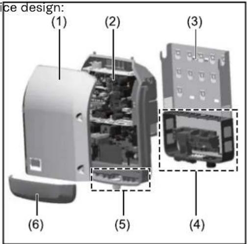
Device concept Device design:
text_image
ce design: (1) (2) (3) (4) (5) (6)(1) Housing cover
(2) Inverter
(3) Mounting bracket
(4) Connection area incl. DC main switch
(5) Data communication area
(6) Data communication cover
The inverter transforms the direct current generated by the solar modules into alternating current. This alternating current is fed into the public grid synchronously with the grid voltage.
The inverter has been developed exclusively for use in grid-connected photovoltaic systems; it is impossible to generate energy independently of the public grid.
The inverter automatically monitors the public grid. In the event of abnormal grid conditions, the inverter ceases operating immediately and stops feeding power into the grid (e.g. if the grid is switched off, if there is an interruption, etc.).
The grid is monitored by monitoring the voltage, frequency and islanding conditions.
The inverter operates fully automatically. As soon after sunrise as there is sufficient energy available from the solar modules, the inverter starts monitoring the grid. When insolation has reached a sufficient level, the inverter starts feeding energy into the grid.
The inverter operates in such a way that the maximum possible amount of power is obtained from the solar modules.
As soon as the power available has fallen below the level at which energy can be
fed into the grid, the inverter disconnects the power electronics completely from the grid and stops running. It retains all its settings and stored data.
If the inverter becomes too hot, it automatically reduces the current output power in order to protect itself.
Reasons for the inverter becoming too hot include the ambient temperature being too high or inadequate heat dissipation (e.g. if it is installed in a switch cabinet without suitable heat dissipation).
Proper use/intended purpose
The inverter is intended exclusively to convert direct current from solar modules into alternating current and to feed this into the public grid.
Utilisation not in accordance with the intended purpose comprises:
- Any use above and beyond this purpose
- Making any modifications to the inverter that have not been expressly approved by Fronius
- the installation of components that are not distributed or expressly approved by Fronius.
Fronius shall not be liable for any damage resulting from such action. No warranty claims will be entertained.
Proper use also includes:
- Carefully reading and obeying all the instructions and all the safety and danger notices in the Operating Instructions and Installation Instructions
- Performing all stipulated maintenance work
- Installation as specified in the Installation Instructions
When designing the photovoltaic system, ensure that all components are operated within their permitted operating ranges at all times.
Observe all the measures recommended by the solar module manufacturer to ensure that the solar module retains its properties in the long term.
Obey the regulations of the power supply company regarding connection methods and energy fed into the grid.
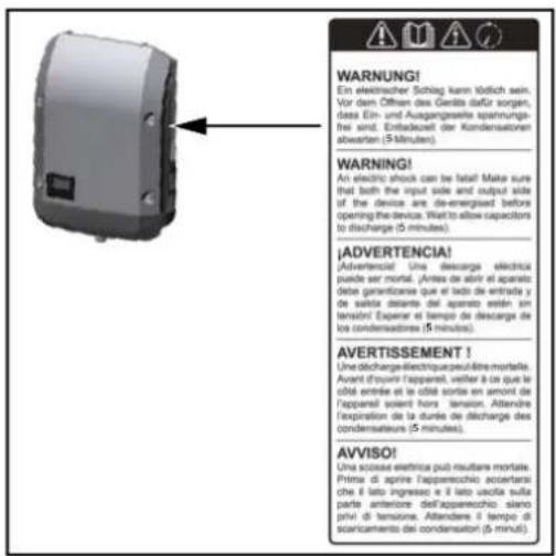
Warning notices on the device
There are warning notices and safety symbols on and in the inverter. These warning notices and safety symbols must not be removed or painted over. They warn against incorrect operation, as this may result in serious injury and damage.
text_image
WARNING! Ein elektrischer Schlag kann tödlich sein. Vor dem Offesen des Gedits dafür sorgen, dass Ein- und Ausgangsante spannungs- frei sind. Endeadeurit der Kondensatoren abwerten (5 Minuten). WARNING! An electric shock can be fatal! Make sure that both the input side and output side of the device are de-emergesed before opening the device. What to allow capacitors to discharge (5 minutes). ¡ADVERTENCIA! Advertencé! Una descarga électrique puede ser mortal. Antesa de partir el aparato debe garantizarse que el tado de entrada y de salida delante del aparato estér sin tensin! Experer el tiempo de descarga de los condensadores (5 minutos). AVERTISSEMENT ! Une d'charge-electricque peut-être mortales. Avent d'ouvrir l'apparel, veiller à ce que le obité entrée et le côte sorte en amont de l'apparel soient hors tension. Attendre l'expiration de la durée de discharge des condensature (5 minutes). AVVISO! Una sciose elektrica può roustare mortale. Prima di aprire l'appareschio: accertanti: che il lato ingresso e il lato vacità sulla parte anteriore dell'appareschio: siano privi di tensione. Attendere il tempo di scantamento dei condensatori (5 minut).Safety symbols:

Danger of serious injury and damage due to incorrect operation

use the functions de- scribed here until you have fully read and understood the following documents:
- These Operating Instructions
- All the Operating Instructions for the system components of the photovoltaic system, especially the safety rules

Dangerous electrical voltage

Wait for the capacitors to discharge.
Symbols on the rating plate:

CE mark – confirms compliance with applicable EU directives and regulations.

WEEE mark – waste electrical and electronic equipment must be collected separately and recycled in an environmentally sound manner in accordance with the European Directive and national law.

RCM mark – tested in accordance with the requirements of Australia and New Zealand.

CMIM mark – tested in accordance with IMANOR requirements for import regulations and compliance with Moroccan standards.
Text of the warning notices:
WARNING!
An electric shock can be fatal. Before opening the device, it must be disconnected at the input and output. Wait for the capacitors to discharge (5 minutes).
Data communication and Fronius Solar Net
Z
Fronius Solar Net and data in- terface
Fronius Solar Net was developed to make system add-ons flexible to use in a variety of different applications. Fronius Solar Net is a data network that enables multiple inverters to be linked up using system add-ons.
It is a bus system that uses a ring topology. One suitable cable is sufficient for communication between one or several inverters that are connected on the Fronius Solar Net using a system add-on.
Similarly, every inverter on the Fronius Solar Net must be assigned a unique number.
Refer to the section entitled "The SETUP menu item" for instructions on how to assign a unique number.
Fronius Solar Net automatically recognises a wide variety of system add-ons.
In order to distinguish between several identical system add-ons, each one must be assigned a unique number.
More detailed information on the individual system add-ons can be found in the relevant operating instructions or on the internet at http://www.fronius.com
More detailed information on cabling Fronius DATCOM components can be found at:
→ http://www.fronius.com/QR-link/4204101938
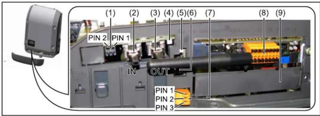
Data communication area
text_image
(1) (2) (3) (4) (5)(6) (7) (8) (9) PIN 2 PIN 1 IN OUT PIN 1 PIN 2 PIN 3Depending on the model, the inverter may be equipped with the Fronius Datamanager plug-in card (8).
| Item Description | |
| (1) Switchable multifunction current interface.For more details, refer to the section below entitled "Explanation of the multifunction current interface"Use the 2-pin mating connector supplied with the inverter to connect to the multifunction current interface. | |
| (2) IN Fronius Solar Net connection / interface protocol IN(3) OUT Fronius Solar Net connection / interface protocol"Fronius Solar Net" / interface protocol input and output for connecting to other DATCOM components (e.g. inverter, Fronius sensor box, etc.)If several DATCOM components are linked together, a terminating plug must be connected to every free IN or OUT connection on a DATCOM component.For inverters with a Fronius Datamanager plug-in card, two terminating plugs are supplied with the inverter. | |
| (4) The "Fronius Solar Net" LEDindicates whether the Fronius Solar Net power supply is available | |
| (5) The "Data transfer" LEDflashes while the USB flash drive is being accessed. The USB flash drive must not be removed while recording is in progress. | |
| (6) USB A socketfor connecting a USB flash drive with maximum dimensions of 65 x 30 mm (2.6 x 2.1 in.)The USB flash drive can function as a datalogger for any inverter that it is connected to. The USB flash drive is not included in the scope of supply of the inverter. | |
| (7) Floating switch contact (relay) with mating connectorMax. 250 V AC / 4 A ACMax. 30 V DC / 1 A DCMax. 1.5 mm^2 (AWG 16) cable cross-sectionPin 1 = NO contact (normally open)Pin 2 = C (common)Pin 3 = NC contact (normally closed)For a more detailed explanation, please see the "Menu items in the Setup menu / Relay" section.Use the mating connector supplied with the inverter to connect to the floating switch contact. | |
| (8) Fronius Datamanager with WLAN antennaorcover for option card compartment | |
| (9) Cover for option card compartment |
Explanation of the multifunction current interface
Various wiring variants can be connected to the multifunction current interface. However, these cannot be operated simultaneously. For example, if an SO meter is connected to the multifunction current interface, it is not possible to connect a signal contact for the surge protection device (or vice versa).
Pin 1 = measurement input: max. 20 mA, 100 Ohm measurement resistor (load impedance)
Pin 2 = max. short circuit current 15 mA, max. open-circuit voltage 16 V DC or GND
Wiring diagram variant 1: Signal contact for surge protective device
Depending on the setting in the Basic menu (Signal Input submenu), the DC SPD option (surge protective device) either outputs a warning or an error on the display. Further information on the DC SPD option can be found in the Installation Instructions.
Wiring diagram variant 2: So meter
A meter for recording the self-consumption of each SO can be connected directly to the inverter. This SO meter can be positioned directly at the feed-in point or in the consumption branch.
IMPORTANT! In order to connect an SO meter to the inverter, it may be necessary to update the inverter firmware.
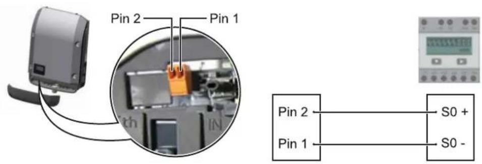
The S0 meter must comply with the IEC62053-31 Class B standard
Recommended max. pulse rate of the SO meter: PV output kWp [kW] Max. pulse rate per kWp
30 1000
20 2000
10 5000
≤ 5.5 10000
With this meter, dynamic power reduction can be performed in two ways:
- Dynamic power reduction by means of inverter
For more information see chapter Dynamic power reduction by means of inverter on page 15 - Dynamic power reduction by means of the Fronius Datamanager 2.0
for more info see: manuals.fronius.com/html/4204260191/#0_m_0000017472
Description of the "Fronius Solar Net" LED
The "Fronius Solar Net" LED is on:
the power supply for data communication within the Fronius Solar Net / interface protocol is OK
The "Fronius Solar Net" LED flashes briefly every 5 seconds:
data communication error in the Fronius Solar Net
- Overcurrent (current flow > 3 A, e.g. resulting from a short circuit in the Fronius Solar Net ring)
- Undervoltage (not a short circuit, voltage in Fronius Solar Net < 6.5 V, e.g. if there are too many DATCOM components on the Fronius Solar Net and not enough electrical power is available)
In this case, power for the Fronius DATCOM components must be supplied by connecting an additional power supply (43,0001,1194) to one of the Fronius DATCOM components.
To detect the presence of an undervoltage, check some of the other Fronius DATCOM components for faults as required.
After cutting out because of overcurrent or undervoltage, the inverter attempts to restore the power supply in the Fronius Solar Net every 5 seconds while the fault is still present.
Once the fault is rectified, power to the Fronius Solar Net will be restored within 5 seconds.
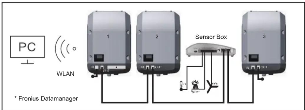
Example Recording and archiving data from the inverter and sensor using a Fronius Datamanager and a Fronius Sensor Box:
text_image
PC WLAN * Fronius Datamanager 1 2 Sensor Box 3 IN OUT IN OUT IN OUT °C W/m² m/sData network with 3 inverters and a Fronius Sensor Box:
- Inverter 1 with Fronius Datamanager
- Inverters 2 and 3 without Fronius Datamanager!
● = Terminating plug
The external communication (Fronius Solar Net) takes place on the inverter via the data communication area. The data communication area contains two RS 422 interfaces as inputs and outputs. RJ45 plug connectors are used to make the connection.
IMPORTANT! Since the Fronius Datamanager functions as a data logger, the Fronius Solar Net ring must not include any other data logger. Only one Fronius Datamanager per Fronius Solar Net ring!
Any other Fronius Datamanagers must be removed and the unoccupied option card compartment sealed off using the blanking cover (42,0405,2020 - available from Fronius as an optional extra); alternatively, use an inverter without Fronius Datamanager (light version).
Installing option cards in the inverter
Information on installing option cards (e.g.: Datamanager) in the inverter and connecting the data communication cable can be found in the Installation Instructions.
Dynamic power reduction by means of inverter
Energy companies or grid operators may impose feed-in limits on an inverter. Dynamic power reduction takes account of self-consumption by the household before the power of an inverter is reduced:
A counter for determining self-consumption of the SO can be connected directly to the inverter – see chapter Explanation of the multifunction current interface on page 12
A feed-in limit can be set in the Basic menu under Signal input – SO meter – see chapter Menu items in the Basic menu on page 43.
Setting options for SO meter:
- Grid feed-in limit
Field for entering the maximum grid feed-in power in W. If this value is exceeded, the inverter regulates down to the set value within the time required by national standards and regulations.
- Pulses per kWh
Field for entering the pulses per kWh of the SO meter.
Zero feed-in is possible with this configuration.
When using the SO meter and power reduction by means of an inverter, the SO meter must be installed in the consumption branch.
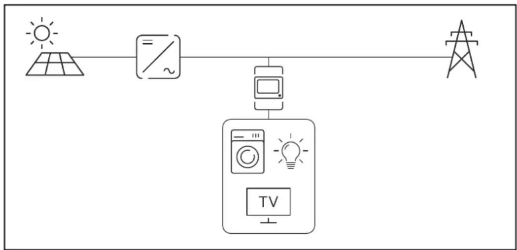
flowchart
graph TD
    A["太阳能板"] --> B["电容/电源符号"]
    B --> C["计算机"]
    C --> D["显示器"]
    D --> E["TV"]
    E --> F["灯泡图标"]
    style A fill:#f9f,stroke:#333
    style B fill:#ccf,stroke:#333
    style C fill:#cfc,stroke:#333
    style D fill:#fcc,stroke:#333
    style E fill:#cff,stroke:#333
So meter in the consumption branch
If dynamic power reduction is subsequently configured using the Fronius Datamanager 2.0 (Inverter user interface - UC Editor menu - Dynamic power reduction), dynamic power reduction must be deactivated using the inverter (Inverter display - Basic menu - Signal input - SO meter).
System monitoring
General The inverter is fitted with the WLAN-enabled system monitoring Fronius
Datamanager 2.0 as standard.
The following functions are included with the system monitoring:
- Dedicated web page displaying current data and a wide range of settings
- Ability to connect to Fronius Solar.web using WLAN or LAN
- Automatic sending of service messages by SMS or e-mail in the event of a fault
- Option of controlling the inverter by specifying power limit values, minimum or maximum running times or target running times
- Control of the inverter via Modbus (TCP / RTU)
- Ability to assign control priorities
- Ability to control the inverter by means of connected meters (Fronius Smart Meter)
- Ability to control the inverter via a ripple control signal receiver (e.g. by specifying the reactive power or effective power)
- Dynamic power reduction, taking self-consumption into account
Further information on Fronius Datamanager 2.0 can be found online in the Fronius Datamanager 2.0 Operating Instructions.
Fronius
Datamanager during the night or when the available DC voltage is insufficient
The Night Mode parameter under "Display Settings" in the Setup menu is preset to OFF in the factory.
For this reason the Fronius Datamanager cannot be accessed during the night or when the available DC voltage is insufficient.
To nevertheless activate the Fronius Datamanager, switch the inverter off and on again at the mains and press any function button on the inverter display within 90 seconds.
See also the chapters on "Menu items in the Setup menu", "Display settings" (Night Mode).
Starting for the first time
Starting the Fronius Datamanager 2.0 for the first time is made considerably easier with the Fronius Solar.start app. The Fronius Solar.start app is available in the respective app stores.

When starting the Fronius Datamanager 2.0 for the first time,
- the Fronius Datamanager 2.0 plug-in card must be installed in the inverter, or
- there must be a Fronius Datamanager Box 2.0 in the Fronius Solar Net ring.
IMPORTANT! In order to establish a connection to Fronius Datamanager 2.0, "Obtain IP address automatically (DCHP)" must be activated on the end device in question (e.g. laptop, tablet, etc.).
NOTE!
If the photovoltaic system has only one inverter, steps 1 and 2 below can be skipped.
In this case, starting for the first time will commence with step 3.
1 Connect inverter with Fronius Datamanager 2.0 or Fronius Datamanager Box 2.0 to the Fronius Solar Net
2 When networking several inverters in Fronius SolarNet:
Set the Fronius Solar Net client/server switch on the Fronius Datamanager 2.0 plug-in card correctly
- One inverter with Fronius Datamanager 2.0 = master - All other inverters with Fronius Datamanager 2.0 = slave (the LEDs on the Fronius Datamanager 2.0 plug-in cards are not illuminated)
3 Switch the device to Service mode - Activate the WiFi Access Point via the Setup menu on the inverter

text_image
SETUP | 1 Stand by WiFi Access Poi DATCOM USB ClockThe inverter establishes the WLAN access point. The WLAN access point remains open for 1 hour. The IP switch on the Fronius Datamanager 2.0 can remain in switch position A due to the activation of the WiFi Access Point.
Installation using the Solar.start app
4 Download Fronius Solar.start

5 Run the Fronius Solar.start app
Installation using a web browser
4 Connect the end device to the WLAN access point
SSID = FRONIUS_240.xxxxx (5-8 digits)
- Search for a network with the name "FRONIUS_240.xxxxx"
- Establish a connection to this network
- Enter the password 12345678
(Alternatively, connect the end device and inverter using an Ethernet cable.)
5 Enter the following in the browser:
http://datamanager or 192.168.250.181 (IP address for WLAN connection) or 169.254.0.180 (IP address for LAN connection)
The Setup wizard start page is displayed.

text_image
Welcome to the Fronius setup wizard. You are just a few steps away from convenient system monitoring. SOLAR WEB WIZARD TECHNICIAN WIZARD Connect the system with the Fronius Solarweb and use our Apps for mobile devices. FURTHER SETTINGS ! For qualified persons only!The technician wizard is intended for the installer and contains standard-specific settings. Running the technician wizard is optional.
If the technician wizard is run, it is vital to note the service password that is issued. This service password is necessary for setting the "DNO Editor" menu item. If the technician wizard is not run, no specifications regarding power reduction are set.
Running the Fronius Solar.web wizards is mandatory.
6 Run the Fronius Solar.web wizards and follow the instructions
The Fronius Solar.web homepage is displayed,
or
the Fronius Datamanager 2.0 web page is displayed.
7 Where necessary, run the technician wizard and follow the instructions
Further information on Fronius Datamanager 2.0
Further information on the Fronius Datamanager 2.0 and other start-up options can be found at:
→ http://www.fronius.com/QR-link/4204260191DE
Controls and dis- plays
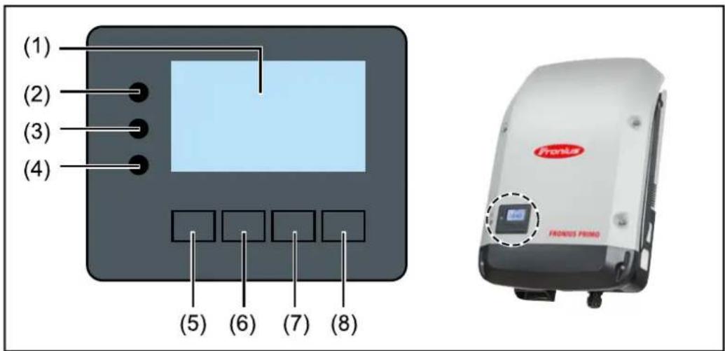
text_image
(1) (2) (3) (4) (5) (6) (7) (8) Pronka Fronkus PRIMOItem Description
(1) Display
For displaying values, settings and menus
Monitoring and status LEDs
(2) General status LED (red) lights up
- if a status message is being displayed on the monitor
- If the process of feeding energy into the grid is interrupted
- During error handling (the inverter waits for an acknowledgement or for an error to be rectified)
(3) Startup LED (orange) lights up
- If the inverter is in its automatic startup or self-test phase (as soon after sunrise as the solar modules are delivering sufficient power)
- If the inverter has been switched to Standby mode in the Setup menu (= feeding energy into the grid switched off manually)
- If the inverter software is being updated
(4) Operating status LED (green) lights up
- If the PV system is working correctly after the inverter's automatic startup phase
- all the time while energy is being fed into the grid
Function keys - allocated different functions depending on the selection:
(5) "Left/up" key
For navigating to the left and up
(6) "Down/right" key
For navigating down and to the right
(7) "Menu/Esc" key
For switching to the menu level
For quitting the Setup menu
(8) "Enter" key
For confirming a selection
The keys are capacitive and any exposure to water can impair their function. Wipe the keys dry with a cloth if necessary to ensure optimum functionality.
Display Power for the display comes from the mains voltage. Depending on the setting selected in the Setup menu, the display can be kept on all day.
IMPORTANT! The display on the inverter is not a calibrated measuring device. A slight inaccuracy in comparison with the energy meter used by the energy company is intrinsic to the system. A calibrated meter will be needed to calculate the bills for the power supply company.
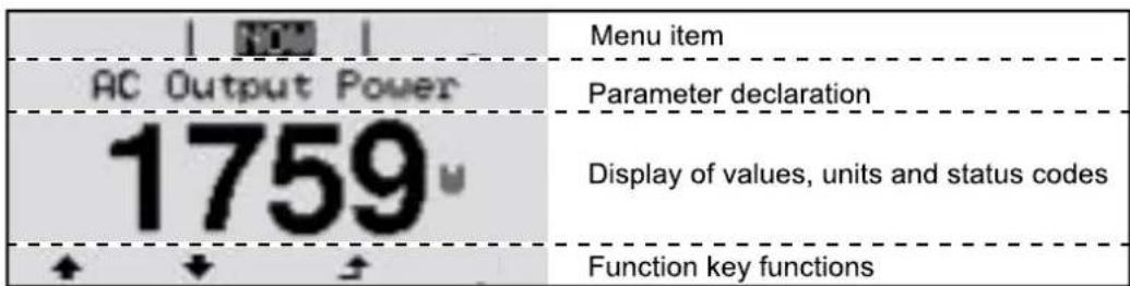
text_image
AC Output Power 1759 Menu item Parameter declaration Display of values, units and status codes Function key functionsDisplay areas in Display mode
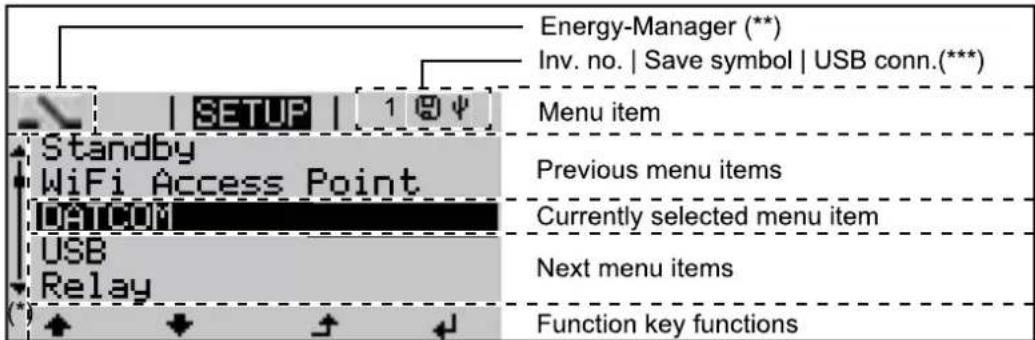
text_image
Energy-Manager (** Inv. no. | Save symbol | USB conn.(***) SETUP | 1 @ψ | Standby WiFi Access Point DATCOM USB Relay Menu item Previous menu items Currently selected menu item Next menu items Function key functionsDisplay areas in Setup mode
(*) Scroll bar
(**) The Energy Manager symbol is displayed when the Energy Manager function is activated
(***) Inv. no. = Inverter DATCOM number,
Save symbol - appears briefly while set values are being saved,
USB connection - appears if a USB stick has been connected
The menu level
Activating dis- play backlighting
1 Press any key
The display backlighting is activated.
There is an option under "Display Settings - Backlighting" in the SETUP menu to set the display backlighting so that it is on all the time or off all the time.
Automatic deactivation of display backlighting / changing to the "NOW" menu item
If two minutes pass without any button being pressed, the display backlighting switches off automatically and the inverter goes to the "NOW" menu item (assuming the display backlighting is set to AUTO).
The automatic selection of the "NOW" menu item can happen from any position on the menu level, unless the inverter was manually switched into the "Standby" operating mode.
After automatically selecting the "NOW" menu item, the current power of feeding in is displayed.
Open menu level
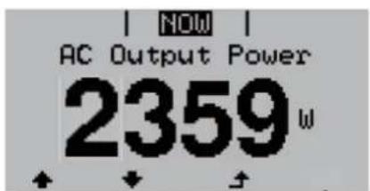
text_image
NOW AC Output Power 2359W1 Press the "Menu" Key
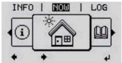
text_image
INFO | NOW | LOG iThe display switches to the menu level.
2 Using the "Left" or "Right" keys select the desired menu item
3 Press the "Enter" key ◄ to select the desired menu item
The NOW, LOG and GRAPH menu items
NOW
LOG
GRAPH
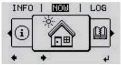
text_image
INFO | NOW | LOG iNOW
(Displays real-time values)
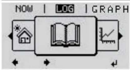
text_image
NOW | LOG | GRAPHLOG
(Data recorded today, during the current calendar year and since the inverter was first commissioned)
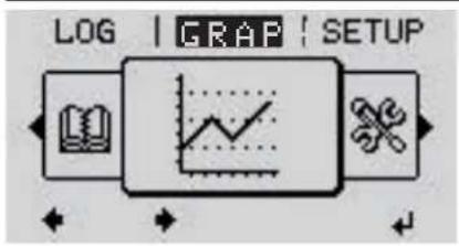
text_image
LOG | GRAP | SETUPGRAPH
Day characteristic
displays a plot showing the output power during the day. The time axis is scaled automatically.
Press the "Back" key to close the display
Values displayed in the NOW and LOG menu items
Values displayed in the NOW menu item:
| AC Output power (W) |
| AC Reactive power (V Ar) |
| AC Voltage (V) |
| AC Output current (A) |
| AC Frequency (Hz) |
| PV Array Voltage (V) |
| PV Array Current (A) |
| Time / dateTime and date on the inverter or in the Fronius Solar Net ring |
Values displayed in the LOG menu item:
(for today, during the current calendar year and since the inverter was started for the first time)
AC Energy Yield (kWh / MWh)
Energy fed into the grid during the period in question
There may be discrepancies with values displayed on other measuring instruments because of differences in measuring methods. As far as the billing of the energy fed in is concerned, the only binding display values are those produced by the calibrated measuring device provided by the electricity supply company.
AC Max. Output Power (W)
Largest amount of power fed into the grid during the period in question
Earnings
Amount of money earned during the period in question (currency can be selected in the Setup menu)
Like the energy supplied figure, the yield figure may also exhibit discrepancies with other measured values.
The 'Setup Menu' section explains how to select a currency and charge rate.
The factory setting depends on the respective country setup.
CO2 savings (g / kg)
CO _2 emissions saved during the period in question
The value for CO_2 savings depends on the power station facilities and corresponds to the CO_2 emissions that would be released when generating the same amount of energy. The factory setting is 0.53 kg / kWh (source: DGS – Deutsche Gesellschaft für Sonnenenergie e.V. (German Society for Solar Energy).
AC Max. Voltage L-N (V)
Highest voltage measured between the conductor and neutral conductor during the period in question
PV Array Max. Voltage (V)
Highest solar module voltage measured during the period in question
Operating Hours
Length of time the inverter has been working (HH:MM).
IMPORTANT! A prerequisite for the correct display of day and year values is that the time is set correctly.
SETUP menu item
Initial setting The inverter is pre-configured after commissioning has been completely carried out (e.g. using the Installation Wizard) according to the country setup.
The SETUP menu item allows the initial settings of the inverter to be changed easily to bring it in line, as closely as possible, with the preferences and requirements of the user.
SETUP
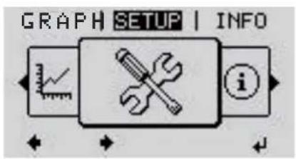
text_image
GRAPH SETUP | INFO iSETUP
(Setup menu)
NOTE!
As a result of software updates, you may find that your device has certain functions that are not described in these Operating Instructions, or vice versa.
Certain illustrations may also differ slightly from the actual controls on your device, but these controls function in exactly the same way.
Navigating the SETUP menu item
Entering the SETUP menu item
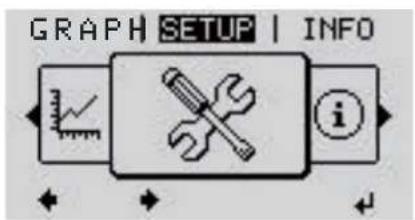
text_image
GRAPH SETUP | INFO iMenu level, "SETUP" selected
At the menu level, use the "Left" or "Right" keys to select the "SETUP" menu item
2 Press the "Enter" Key
The first entry under the SETUP menu item is displayed:
"Standby"
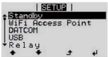
text_image
| SETUP | Standby WiFi Access Point DATCOM USB Relay"Standby" entry
Scrolling between the entries
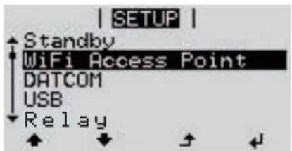
text_image
| SETUP | Standby WiFi Access Point DATCOM USB RelayExample: "WiFi Access Point" menu item
3 Use the "Up" and "Down" keys to scroll between the available entries
Exiting an entry
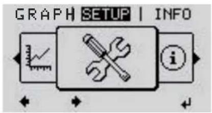
text_image
GRAPH SETUP | INFO4 To exit a menu entry, press the "Back" key
The menu level appears
If no key is pressed for 2 minutes:
- The inverter switches from wherever it is on the menu level back to the "NOW" display mode (exception: "Standby" Setup menu entry),
- The display backlighting goes out.
- The amount of power currently being fed in is displayed.
Setting menu entries, general
1 Open the desired menu
2 Use the 'Up' or 'Down' keys to select the desired menu item
3 Press "Enter"
The available settings are displayed: The first digit of a value to be set flashes:
4 Use the 'Up' or 'Down' buttons to select the desired setting
5 Press the 'Enter' key to save and apply the setting.
To discard the setting, press the 'Esc' key.
4 Use the 'Up' or 'Down' keys to select a value for the first digit
5 Press "Enter"
The second digit of the value flashes.
6 Repeat steps 4 and 5 until ...
the whole value to be set flashes.
7 Press "Enter"
8 Repeat steps 4 - 6 as required for units or other values that are to be set until the appropriate unit or the value flashes.
9 Press the 'Enter' key to save and apply the changes.
To discard the changes, press the 'Esc' key.
The currently selected menu item is displayed.
The currently selected menu item is displayed.
Application example: Setting the time

text_image
| SETUP | 1 | USB Relay Clock Display Setting Energy Yield1 Select "Clock" from the Setup menu
2 Press the "Enter" Key
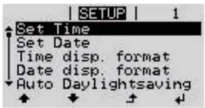
text_image
SETUP | 1 Set Time Set Date Time disp. format Date disp. format Auto DaylightsavingAn overview of the values that can be changed is displayed.
3 Use the "Up" and "Down" keys Select "Set time"
4 Press the "Enter" Key
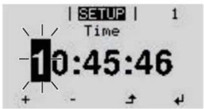
text_image
| SETUP | 1 Time 10:45:46The current time appears. (HH:MM:SS, 24-hour clock), the "tens" digit for the hour will flash.
5 Use the "Up" and "Down" keys to select a value for the first digit of the code
6 Press the "Enter" Key
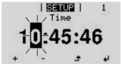
text_image
| SETUP | 1 Time 10:45:46The "units" digit for the hour will flash.
7 Repeat steps 5 and 6 to set the "units" digit for the hour, for the minutes and for the seconds until...
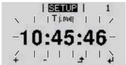
text_image
SETUP | 1 、 | | Time | | / -10:45:46 - + - + +the set time starts flashing.
8 Press the "Enter" Key
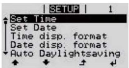
text_image
SETUP | 1 Set Time Set Date Time disp. format Date disp. format Auto DaylightsavingThe time is applied and the overview of values that can be changed is displayed.
4 Press the "Esc" key
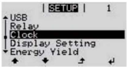
text_image
| SETUP | 1 | USB Relay Clock Display Setting Energy YieldThe "Clock" item on the Setup menu appears.
The Setup menu items
Standby Manual activation / deactivation of Standby mode
- No energy is fed into the grid.
- The Startup LED will show steady orange.
- In the display, STANDBY / ENTER are alternately displayed
- In Standby mode, no other menu item at menu level can be accessed or adjusted.
- The automatic switchover into the "NOW" display mode after 2 minutes of keyboard inactivity does not occur.
- Standby mode can only be terminated manually by pressing the "Enter" key.
- Pressing "Enter" at any time will cause energy to resume feeding into the grid, as long as there is no error (state code)
Switching off Standby mode (manually switching off feeding energy into the grid):
1 Select the "Standby" item
2 Press "Enter" function ↓key
"STANDBY" and "ENTER" appear alternately on the display.
Standby mode is now active.
The Startup LED shows steady orange.
Resuming feeding energy into the grid:
In standby mode, the display alternates between 'STANDBY' and 'ENTER'.
1 Press the "Enter" function key to resume feeding energy into the grid
The "Standby" menu item is displayed.
At the same time, the inverter enters the startup phase.
The operating state LED shows steady green when feeding energy into the grid has been resumed.
WiFi Access Point
Activating / deactivating the WiFi Access Point. This is necessary for setting up or adjusting system monitoring using the Datamanager web interface, for example. If no Datamanager is detected by the inverter, [not available] is displayed
| Setting range WiFi Access Point [stopped] |
| Activate WiFi AP? |
| To activate the WiFi Access Point ← Press the "Enter" key |
| WiFi Access Point [active] |
| The SS-ID (SS) and password (PW) are displayed. |
| Deactivate WiFi AP? |
| To deactivate the WiFi Access Point ← Press the "Enter" key |
DATCOM Checking data communications, entering the inverter number, protocol settings
Setting range Status / inverter number / protocol type
Status
Indicates data communication is taking place via Fronius Solar Net or that a data communications error has occurred
Inverter number
Sets the number (= address) of the inverter in a system with several inverters
Setting range 00 - 99 (00 = inverter address 100)
Factory setting 01
IMPORTANT! If a number of inverters are linked together in a data communications system, assign a unique address to each one.
Protocol type
Specifies the communications protocol to be used to transfer the data:
Setting range Solar Net / Interface *
Factory setting Fronius Solar Net
* The protocol type "Interface" only functions when there is no Datamanager card in the inverter. All Fronius Datamanager cards should be removed from the inverter.
USB Running firmware updates or saving detailed information from the inverter to the USB flash drive
Setting range Safely remove hardware / Software update / Logging interval
Safely remove hardware
To remove a USB flash drive from the USB A socket on the plug-in data communications card without losing any data.
The USB flash drive can be removed:
- If the OK message appears
- when the "Data transfer" LED stops flashing or comes on steady
Software update
To update the inverter firmware using a USB flash drive.
Procedure:
1 Download the relevant firmware update file "froxxxx.upd" (e.g. from http://www.fronius.com; xxxx stands for the version number)
NOTE!
To successfully update the inverter software, the USB flash drive provided for the purpose must not have a hidden partition or any encryption (see chapter "Suitable USB flash drives").
2 Save the firmware update file to the highest data level of the USB flash drive
3 Open the lid of the data communication area on the inverter
4 Plug the USB flash drive containing the firmware update file into the USB socket in the inverter's data communication area
5 Select "USB" from the Setup menu, followed by "Software update"
6 Press the "Enter" key
7 Wait until the version currently installed on the inverter and the new firmware version are displayed for comparison:
- First Page: Recerbo software (LCD), key controller software (KEY), country setup version (Set)
- Second Page: Power stage set software (PS1/PS2)
8 Press the "Enter" function button after each page
The inverter starts copying the data.
"BOOT" and the progress of storing the individual tests expressed in % are displayed until all the data for all the electronic modules has been copied.
Once copying is complete, the inverter updates the electronic modules as required in sequence.
"BOOT", the affected modules and the update progress in % are displayed.
The final step is for the inverter to update the display.
The display remains dark for approx. 1 minute while the monitoring and status LEDs flash.
Once the firmware update is complete, the inverter enters its start-up phase before going on to start feeding energy into the grid. Unplug the USB flash drive using the "Safely remove hardware" function.
When the inverter firmware is updated, any custom settings that were configured in the Setup menu are retained.
Logging interval
Activate / deactivate the USB logging function and specify a logging interval
Unit Minutes
Setting range 30 min. / 20 min./ 15 min./ 10 min./ 5 min./ No log
Factory setting 30 min.
30 min. The logging interval is 30 minutes; every 30 minutes new logging data will be saved to the USB flash drive.
20 min.
15 min.
10 min.
5 min. The logging interval is 5 minutes; every 5 minutes new logging data will be saved to the USB flash drive.
No log No data is saved
IMPORTANT! In order for the USB logging function to work correctly the time must be set correctly. Setting the time is discussed in the section "Menu items in the Setup menu" - "Clock".
Relay (floating contact switch)
Status codes (state codes), the status of the inverter (e.g. feeding energy into the grid) or Energy Manager functions can be displayed using the floating switch contact (relay).
Setting range Relay mode / Relay test / Switch-on point* / Switch-off point*
* these are only shown if the "E-Manager" function has been activated under "Relay mode".
Relay mode
The following functions can be shown using relay mode:
- Alarm function (Permanent / ALL / GAF)
- Active output (ON / OFF)
- Energy Manager (E-Manager)
Setting range ALL / Permanent / GAF / OFF / ON / E-Manager
Factory setting ALL
Alarm function:
ALL / Per- manent:
Switching the floating switch contact for permanent and temporary service codes (e.g. brief interruption to energy being fed into the grid, a service code occurs a certain number of times a day - can be adjusted in the "BASIC" menu)
GAF As soon as GAF mode is selected, the relay is switched on.
The relay opens as soon as the power stage set registers an error and goes from normally feeding energy into the grid to being in an error state. This means that the relay can be used for fail-safe functions.
Application example
It may be necessary to perform phase compensation when using a single-phase inverter at a multiphase site. If an error occurs on one or several inverters and the connection to the grid is broken, the other inverters must also be disconnected to maintain the phase balance. The "GAF" relay function can be used in conjunction with the Datamanager or an external protection device to recognise or signal that an inverter is not feeding in or is disconnected from the grid and to then disconnect the remaining inverters from the grid using a telecontrol command.
Active output:
ON: The floating NO contact is on all the time the inverter is in operation (as long as the display is not dark or is displaying something).
OFF: The floating NO contact is off.
Energy Manager:
E-Manager: Further details on the "Energy Manager" function may be found in the "Energy Manager" section.
Relay test
Function test to determine whether the floating switch contact switches
Switch-on point (only if "Energy Manager" function is activated)
for setting the effective power limit beyond which the floating switch contact is switched on
Factory setting 1000 W
Setting range Set switch-off point up to the maximum nominal output of the inverter (W or kW)
Switch-off point (only if "Energy Manager" function is activated)
for setting the effective power limit beyond which the floating switch contact is switched off
Factory setting 500
Setting range 0 to the set switch-on point of the inverter (W or kW)
Energy Manager (under Relay menu item)
The "Energy Manager" (E-Manager) function can be used to activate the floating switch contact in such a way that it functions as an actuator.
Thus, a consumer that is connected to the floating switch contact can be controlled by specifying a switch-on or switch-off point that depends on the feed-in power (effective power).
The floating switch contact is automatically switched off:
- If the inverter is not feeding any power into the grid
- If the inverter is manually switched to Standby mode
- If the effective power is set to < 10% of the nominal output of the inverter.
To activate the Energy Manager function, select the "E-Manager" item and press the "Enter" key.
When the "Energy Manager" function is running, the "Energy Manager" symbol will appear in the top left corner of the display:
When the floating NO contact is off (open contact)
When the floating NC contact is on (closed contact)
To deactivate the Energy Manager function, select a different function (ALL / Permanent / OFF / ON) and press the "Enter" key.
NOTE!
Notes on setting up the switch-on and switch-off points If the difference between the switch-on and switch-off points is too small, or if there are fluctuations in effective power, the result may be multiple switching cycles.
To avoid switching on and off frequently, the difference between the switch-on and switch-off points should be at least 100 - 200 W.
When choosing the switch-off point, the power consumption of the connected consumer should be taken into account.
When choosing the switch-on point, the weather conditions and anticipated insolation should be taken into account.
Application example
Switch-on point = 2000 W, switch-off point = 1800 W
If the inverter is outputting 2000 W or above, then the floating switch contact on the inverter is switched on.
If the inverter output falls to below 1800 W, the floating switch contact is switched off.
This allows useful applications, such as operating a heat pump or an air-conditioning system using as much self-generated power as possible, to be implemented quickly
Time / Date Set the time, date, the display format and automatic changeover between summer and winter time
Setting range Set time / Set date / Time display format / Date display format / Summer/winter time
Set time
Set the time (hh:mm:ss or hh:mm am/pm – depending on the setting for the time display format)
Set date
Set the date (dd.mm.yyyy or mm/dd/yyyy - depending on the setting for the date display format)
Time display format
For specifying the time display format
Setting range 12hrs / 24hrs
Factory setting Depends on country setup
Date display format
for specifying the date display format
Setting range mm/dd/yyyy or dd.mm.yy
Factory setting Depends on country setup
Summer/winter time
Activate/deactivate automatic changeover between summer and winter time
IMPORTANT! Only use the automatic summer/winter time changeover function if the Fronius Solar Net ring does not include any LAN- or WLAN-compatible system components (e.g. Fronius Datalogger Web, Fronius Datamanager or Fronius Hybridmanager).
Setting range on / off
Factory setting on
IMPORTANT! The time and date must be set accurately in order for the day and year values and for the day characteristic to be displayed correctly.
Display settings
Setting range Language / Night mode / Contrast / Illumination
Language
Set language for display
Setting range English, German, French, Spanish, Italian, Dutch, Czech, Slovakian, Hungarian, Polish, Turkish, Portuguese, Romanian
Night mode
Night mode controls Fronius DATCOM and inverter display operation during the night or when the DC voltage is insufficient
Setting range AUTO / ON / OFF
Factory setting OFF
AUTO: Fronius DATCOM mode is always in effect as long as there is a Fronius Datamanager connected in an active and uninterrupted Fronius Solar Net. The inverter display remains dark during the night, but can be activated by pressing any function button.
ON: Fronius DATCOM mode is always in effect. The inverter supplies 12 V of DC voltage continuously to power the Fronius Solar Net. The display is always active.
IMPORTANT! If Fronius DATCOM night mode is set to ON or AUTO when there are Fronius Solar Net components connected, the inverter's current consumption during the night will increase to around 7 W.
OFF: Fronius DATCOM will not run at night, the inverter therefore does not require any power during the night to supply the Fronius Solar Net with energy. The inverter display is switched off during the night and the Fronius Datamanager is not available. To nevertheless activate the Fronius Datamanager, switch the inverter off and on again at the mains and press any function button on the inverter display within 90 seconds.
Contrast
Set the contrast on the inverter display
Setting range 0 - 10
Factory setting 5
Since the contrast is temperature-dependent, it may be necessary to adjust the setting under the "Contrast" menu item when the environmental conditions change.
Illumination
Initial setting for inverter display illumination
The "Illumination" menu item only relates to the inverter display backlighting.
Setting range AUTO / ON / OFF
Factory setting AUTO
AUTO: The inverter display backlighting is activated by pressing any key. If no key is pressed for 2 minutes, the display backlighting will go off again.
ON: The inverter display backlighting remains permanently on when the inverter is active.
OFF: The inverter display backlighting is permanently switched off.
ENERGY YIELD The following settings can be changed/set here:
- Counter deviation / Calibration
- Currency
- Feed-in tariff
- CO2 factor
Setting range Currency / Feed-in tariff
Counter deviation / calibration Calibrating the counter
Currency Set the currency
Setting range 3 characters, A-Z
Feed-in tariff Set the remuneration rate for energy fed into the grid
Setting range 2 digits, 3 decimal places Factory setting (depends on country setup)
CO2 factor Setting the CO2 factor of the energy fed into the grid
Fan To check that the fan is working correctly
Setting range Test fan #1 / Test fan #2 (depending on the device)
- Use the "Up" and "Down" keys to select the desired fan
- Testing of the selected fan is initiated by clicking "Enter".
- The fan will continue to run until the operator exits the menu by pressing "Esc".
IMPORTANT! Nothing will show on the inverter display if the fan is working. The only way to check how the fan is working is by listening and feeling.
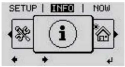
INFO
text_image
SETUP | INFO | NOWINFO
(Information about the device and the software)
Measured values PSS status Grid status
Measured values
Display range: PV ins. / Ext. lim. / U PV1 / U PV2 / GVDPR / Fan #1
PV ins.
Insulation resistance of the PV system (with unearthed solar modules and solar modules with negative pole earthing)
Ext. lim.
External power reduction in per cent e.g. specified by grid operator
UPV1
Current DC voltage on the terminals, even if the inverter is feeding no power into the grid whatsoever (from the 1st MPP tracker)
UPV2
Current DC voltage on the terminals, even if the inverter is feeding no power into the grid whatsoever (from the 2nd MPP tracker)
GVDPR
Grid voltage-dependent power reduction
Fan #1
Percentage of target output for fan
PSS status The status of the most recent inverter fault can be displayed.
IMPORTANT! Due to the low level of insolation early in the morning and in the evening, the status codes 306 (Power low) and 307 (DC low) are displayed routinely at these times of day. These status codes do not indicate any kind of fault.
- Press the "Enter" key to see the status of the power stage set and the most recent fault
- Use the "Up" and "Down" keys to scroll through the list
- Press the "Back" key to close the status and fault list
Grid status The five most recent grid faults can be displayed:
- Press the 'Enter' key to see the five most recent grid faults
- Use the "Up" and "Down" keys to scroll through the list
- Press the 'Back' key to close the grid fault display
| Device information | For displaying the settings that will be of relevance to a power supply company. The values shown will depend on the country setup or the device-specific settings of the inverter. |
| Display area General / Country-specific setting / MPP tracker / Grid monitoring / Grid voltage limits / Grid frequency limits / Q-mode / AC power limit / AC voltage derating / Fault Ride Through | |
| General: Device type - the exact name of the inverterfam. - inverter family of the inverterserial number - serial number of the inverter | |
| Country-specific setting: | Setup - specified country setupVersion - version of country setupOrigin activated - indicates that the normal country-specific setup is activated.Alternat. activated - indicates that the alternative country-specific setup is activated (for Fronius Symo Hybrid only)Group - group for updating the inverter software |
| MPP Tracker: Tracker 1 - indicates the set tracking behaviour (MPP AUTO / MPP USER / FIX)Tracker 2 (only on Fronius Symo except for Fronius Symo 15.0-3 208) - indicates the set tracking behaviour (MPP AUTO / MPP USER / FIX) | |
| Grid monitoring: GMTi - Grid Monitoring Time - start-up time of the inverter in sec (seconds)GMTr - Grid Monitoring Time reconnect - reconnection time in sec (seconds) after a grid faultULL - U (voltage) Longtime Limit - voltage limit value in V (volts) for the 10-minute average voltage valueLLTrip - Longtime Limit Trip - trip time for ULL monitoring, how fast the inverter should switch off | |
| Grid voltage limitsinner limit value: | UImax - upper inner grid voltage in V (volts)TTMax - Trip Time Max - trip time for exceeding the upper inner grid voltage limit value in cyl*UMin - lower inner grid voltage in V (volts)TTMin - Trip Time Min - trip time for falling below the lower inner grid voltage limit value in cyl**cyl = grid periods (cycles); 1 cyl corresponds to 20 ms at 50 Hz or 16.66 ms at 60 Hz |
| Grid voltage limits outer limit value | UMax - upper outer grid voltage in V (volts) |
| TTMax - Trip Time Max - trip time for exceeding the upper outer grid voltage limit value in cyl* | |
| UMin - lower outer grid voltage in V (volts) | |
| TTMin - Trip Time Min - trip time for falling below the lower outer grid voltage limit value in cyl* | |
| * cyl = grid periods (cycles); 1 cyl corresponds to 20 ms at 50 Hz or 16.66 ms at 60 Hz | |
| Grid frequency lim-its: | FILmax - upper inner grid frequency in Hz (Hertz) |
| FILmin - lower inner grid frequency in Hz (Hertz) | |
| FOLmax - upper outer grid frequency in Hz (Hertz) | |
| FOLmin - lower outer grid frequency in Hz (Hertz) | |
| Q-mode: Indicates which reactive power setting is currently active on the inverter (e.g.OFF, Q / P, etc.) | |
| AC power limit in-cluding SoftStart ind-icator and/or AC grid frequency de-rating: | Max P AC - maximum output power, which can be changed using the "Manu-al Power Reduction" function |
| GPIS - Gradual Power Incrementation at Startup - indicates (%/sec) wheth-er the SoftStart function is active on the inverter | |
| GFDPRe - Grid Frequency Dependent Power Reduction enable limit - indic-ates the set grid frequency in Hz (Hertz) from when power derating takes place | |
| GFDPRv - Grid Frequency Dependent Power Reduction derating gradient - indicates the set grid frequency in %/Hz, how strong power derating is | |
| AC voltage derating: | GVDPRe - Grid Voltage Depending Power Reduction enable limit - threshold value in V from which voltage-dependent power derating starts |
| GVDPRv - Grid Voltage Depending Power Reduction derating gradient - de-rating gradient %/V with which the power is reduced | |
| Message - indicates whether the dispatch of an info message via Fronius Sol-ar Net is active | |
Version Displays the version and serial numbers of the PC boards in the inverter (e.g. for service purposes)
Display area Display / Display Software / Integrity Checksum / Memory Card / Memory Card #1 / Power Stage / Power Stage Software / EMI Filter / Power Stage #3 / Power Stage #4
Switching the key lock on and off
General The inverter has a key lock function.
When the key lock is active, the Setup menu is not accessible, i.e. the setup data cannot be changed accidentally (or maliciously).
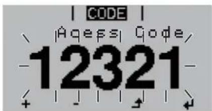
The code 12321 has to be entered in order to activate / deactivate the key lock.
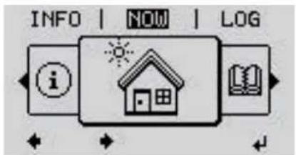
Switching the key lock on and off
text_image
INFO | NOW | LOG i1 Press the "Menu" key
The menu level appears.
2 Press the unassigned "Menu / Esc" key 5 times □ □ □ □
text_image
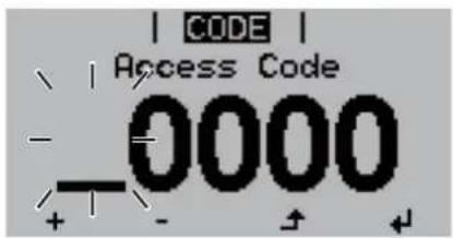
CODE Access Code -0000 + - + +"Access Code" is displayed in the "CODE" menu; the first digit starts flashing.
3 Enter the code 12321: Use the "Plus" and "Minus" keys to select a value for the first digit of the code
4 Press the "Enter" key
text_image
CODE Aqessi Code/ 12321The second digit flashes.
5 Repeat steps 3 and 4 for the second, third, fourth and fifth digits of the access code until...
the selected code starts flashing.
6 Press the "Enter" key
text_image
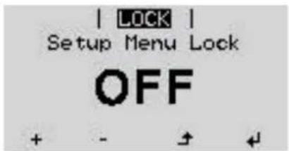
| LOCK | Setup Menu Lock OFF + - + ↓"Setup Menu Lock" is displayed in the "LOCK" menu.
7 Use the "Plus" and "Minus" keys to turn the key lock on or off:
ON = key lock is on (the Setup menu is not accessible)
OFF = key lock is off (the Setup menu is accessible)
8 Press the "Enter" key
USB Stick as a Data Logger and for Updating Inverter Software
EN
USB flash drive as a datalogger
If a USB flash drive is connected to the USB A socket it can function as a datalogger for an inverter.
At any time, the logging data stored on the USB flash drive can be
- imported into the Fronius Solar.access software using the FLD file that was logged at the same time,
- viewed directly in third-party programs (e.g. Microsoft® Excel) using the CSV file logged at the same time.
Older versions (before Excel 2007) are limited to a maximum of 65,536 rows.
Further information on "Data on a USB flash drive", "Data volume and storage capacity" as well as "Buffer memory" can be found at:
→ http://www.fronius.com/QR-link/4204260204DE
Suitable USB flash drives
Due to the variety of USB flash drives available on the market, it cannot be guaranteed that every USB flash drive will be detected by the inverter.
Fronius recommends that only certified, industry-grade USB flash drives are used (look out for the USB-IF logo).
The inverter supports USB flash drives with the following file systems:
- FAT12
- FAT16
- FAT32
Fronius recommends that the USB flash drive employed should only be used for recording logging data or updating the inverter software. The USB flash drives should not contain any other data.
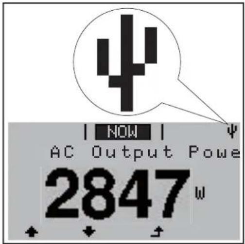
USB symbol on the inverter display, e.g. in display mode 'NOW':
text_image
↓ | NOW | ↓ AC Output Powe 2847WIf the inverter detects a USB flash drive, the USB symbol will appear in the top right corner of the display.
When inserting a USB flash drive, check whether the USB symbol is displayed (it may also flash).
Note! Please note for outdoor applications that conventional USB flash drives are often only guaranteed to work within a restricted temperature range. For outdoor applications ensure that the USB flash drive also functions, for example, at low temperatures.
USB stick for up- dating the in- verter software
With the help of the USB stick, end customers can also update the inverter software via the USB item on the SETUP menu: the update file is first saved to the USB stick, from where it is then transferred to the inverter. The update file must be saved in the root directory on the USB stick.
Removing the USB flash drive
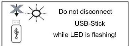
Safety instruction concerning the removal of a USB flash drive:
text_image
Do not disconnect USB-Stick while LED is flashing!IMPORTANT! To avoid any loss of data, a USB flash drive may only be removed if the following conditions are met:
- Only remove a USB flash drive via the 'Safely remove USB / HW' item on the SETUP menu
- The 'Data transmission' LED has stopped flashing or comes on steady.
General The Basic menu is used to set the following parameters, which are important for installing and operating the inverter:
- DC operating mode - Grounding mode / grounding
- Fixed voltage monitoring
- MPPT1 / MPPT2 start voltage - Insulation settings
- USB logbook - TOTAL reset
- Event counter
Access the Basic menu
text_image
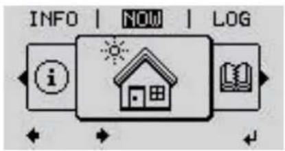
INFO | NOW | LOG i1 Press the "Menu" button
The menu level appears.
2 Press the unassigned "Menu / Esc" key 5 times □ □ □ □
text_image
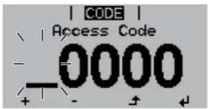
CODE Access Code -0000 + - + +"Access Code" is displayed in the "CODE" menu; the first digit starts flashing.
3 Enter the code 22742: Use the "Plus" and "Minus" keys to select a value for the first digit of the code
4 Press the "Enter" Button
text_image
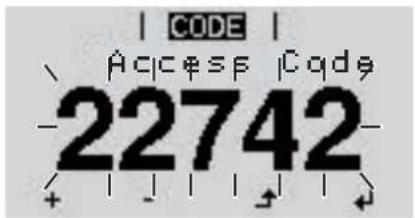
CODE AAccess Code -22742-The second digit flashes.
5 Repeat steps 3 and 4 for the second, third, fourth and fifth digits of the access code until...
the selected code starts flashing.
6 Press the "Enter" Button
The Basic menu appears.
7 Use the "Plus" and "Minus" keys to select the desired entry
8 Edit the desired menu item by pressing the "Enter" button
9 Press the "Esc" key to exit the Basic menu
Menu items in the Basic menu
The Basic menu is used to set the following parameters, which are important for installing and operating the inverter:
MPP Tracker 1 / MPP Tracker 2
- MPP Tracker 2: ON / OFF (only for devices with multiple MPP trackers)
- DC operating mode: MPP AUTO / FIX / MPP USER
- MPP AUTO: normal operating status; the inverter automatically searches for the ideal operating point
- FIX: for entering a fixed DC voltage at which the inverter will operate
- MPP USER: for entering a lower MP voltage above which the inverter will search for its ideal operating point
- Dynamic Peak Manager: ON / OFF
- Fixed voltage: for inputting a fixed voltage (80–800 V)
- MPPT start-up input voltage: for entering the start-up input voltage (80–800 V)
USB log book
Activates or deactivates the function for saving all error messages to a USB flash drive
AUTO / OFF / ON
Input signal
- Ext Sig. / So-Meter / OFF operating mode
Ext Sig. operating mode:
- Triggering method: Warning (warning shown on display) / Ext. Stop (inverter switches off)
- Connection type: N/C (normally closed contact) / N/O (normally open contact)
SO meter operating mode - see chapter Dynamic power reduction by means of inverter on page 15.
- Grid feed-in limit
Field for entering the maximum grid feed-in power in W. If this value is exceeded, the inverter regulates down to the set value within the time required by national standards and regulations.
- Pulses per kWh
Field for entering the pulses per kWh of the SO meter.
SMS / relay
- Event delay:
for entering the time delay after which an SMS is sent or the relay is to switch
900–86,400 seconds
- Event counter:
for entering the number of events that lead to signalling: 10–255
Isolation setting
- Isolation warning: ON / OFF
- Threshold warning: for entering a threshold that leads to a warning
TOTAL Reset
Under the LOG menu item, this setting resets the max. and min. voltage values and the max. power of feeding in to zero.
Once the values have been reset, this action cannot be undone.
To reset the values to zero, press the 'Enter' key.
'CONFIRM' is displayed.
Press 'Enter' again.
The values are reset and the menu is displayed
Switching off current supply and restarting the inverter
Z
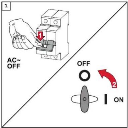
Switch off power to the inverter
text_image
1 AC~ OFF OFF 2 ON- Turn off the automatic circuit breaker.
- Turn the DC disconnector to the "Off" switch position.
To start up the inverter again, follow the steps listed above in reverse order.
Status diagnostics and troubleshooting
Status code dis- play
The inverter performs a system self-diagnosis that automatically detects many faults that may occur and shows them on the display. This means you are promptly made aware of malfunctions in the inverter or the photovoltaic system, or of any installation or operating faults.
If the system self-diagnosis has detected a specific fault, the associated status code will be shown on the display.
IMPORTANT! Status codes may sometimes appear briefly as a result of the inverter's control response. If the inverter then continues working with no sign of any problem, this means that there was no fault.
Total failure of the display
If the display fails to come on some time after sunrise:
- Check the AC voltage ON the inverter connections: the AC voltage must be 230 V (+ 10 % / - 5 %)*.
* The mains voltage tolerance depends on the country setup
Status codes in the e-Manual
The latest status codes can be found in the e-Manual version of these Operating Instructions:
manuals.fronius.com/html/4204102165/#o_t_0000000061
text_image
QR code image containing encoded data, no visible human-readable textmanuals.fronius.com/html/4204102165/#0_t_0000000061
STATE CODES Fronius Primo
Customer service
IMPORTANT! Contact your Fronius dealer or a Fronius-trained service technician if
- an error appears frequently or all the time
- an error appears that is not listed in the tables
Operation in dusty environ- ments
When operating the inverter in extremely dusty environments: when necessary, clean the cooling elements and fan on the back of the inverter as well as the air intakes at the mounting bracket using clean compressed air.
General data and protection devices Fronius Primo 3.0-1 - 8.2-1
| Self-consumption at night 0.6 W | ||
| Cooling Controlled forced-air ventila- | tion | |
| Protection class IP 65 | ||
| Dimensions h x w x d 628 x 428 x 205 mm | ||
| Weight 21.6 kg | ||
| Permitted ambient temperature -40 °C - +55 °C | ||
| Permissible humidity 0 - 100% | ||
| EMC emission class | B | |
| DC / AC overvoltage category | ||
| Inverter topology | Non-insulated transformer-less | |
| Voltage classification | AC | DVC-C |
| Decisive Voltage Classification (DVC rating) | DC | DVC-C |
| Data | DVC-A | |
| Protection devices | ||
| DC isolation measurement | Warning/shutdown 2) at R_ISO < 1 MOHM | |
| Manifestation of DC overload | Operating point shift, power limiter | |
| DC disconnector | Integrated | |
| Active anti-islanding method | Frequency conversion meth- od | |
| Fronius Primo | 3.0-1 | 3.5-1 | 3.6-1 |
Input data
| MPP voltage range | 200 - 800 V |
| Max. input voltage at 1000 W/m2/14 °C in an open circuit | 1000 V |
| Max. input current (MPPT 1 / MPPT 2) | 12.0 A |
| Max. short circuit current of the solar modules (MPPT1 / MPPT2) 8) | 24 / 24 A |
| Max. inverter backfeed current to the array 3) | 18 A |
Output data
| Fronius Primo 3.0-1 3.5-1 3.6-1 | |||
| Rated power (Pnom) 3000 W 3500 W 3680 W | |||
| Max. output power 3000 W 3500 W 3680 W | |||
| Rated apparent power 3000 VA 3500 VA 3680 VA | |||
| Nominal grid voltage 1 ~ NPE 220 / 230 / 240 V | |||
| Min. grid voltage | Inverter topology 150 V 1) | ||
| Max. grid voltage | 270 V 1) | ||
| Max. output current 13.7 A 16.0 A 16.8 A | |||
| Nominal frequency | 50 / 60 Hz 1) | ||
| Total harmonic distortion < 3% | |||
| Power factor (cos phi) | 0.85 - 1 ind./cap. 2) | ||
| Max. permitted mains impedance Zmax at PCC | None | ||
| Current (inrush) 5) | 36 A / 2.2 ms | ||
| Max. output fault current / duration 38 A / 172 ms | |||
Efficiency
| Maximum efficiency | 98.0% | 98.0% | 98.0% |
| European efficiency | 96.1% | 96.8% | 96.8% |
| Fronius Primo | 4.0-1 | 4.6-1 | 5.0-1 |
Input data
| MPP voltage range | 210 - 800 V | 240 - 800 V | 240 - 800 V |
| Max. input voltageat 1000 W/m2/14 °C in an open circuit | 1000 V | ||
| Max. input current (MPPT 1 / MPPT 2) | 12.0 A | ||
| Max. short circuit current of the solar modules(MPPT1 / MPPT2)8) | 24 / 24 A | ||
| Max. inverter backfeed current to the array3) | 18 A | ||
Output data
| Rated power (Pnom) 4000 W 4600 W | 5000 W | ||
| Max. output power 4000 W 4600 W | 5000 W | ||
| Rated apparent power 4000 VA 4600 VA | 5000 VA | ||
| Nominal grid voltage 1 ~ NPE 220 / 230 / 240 V | |||
| Min. grid voltage | 150 V^1) | ||
| Max. grid voltage | 270 V^1) | ||
| Max. output current | 18.3 A | 21.1 A | 22.9 A |
| Fronius Primo 4.0-1 4.6-1 5.0-1 | |||
| Nominal frequency | 50 / 60 Hz 1) | ||
| Total harmonic distortion < 3 % | |||
| Power factor (cos phi) | 0.85 - 1 ind./cap. 2) | ||
| Max. permitted mains impedance Z_max at PCC | None | ||
| Current (inrush) 5) | 36 A / 2.2 ms | ||
| Max. output fault current / duration 38 A / 172 ms | |||
Efficiency
| Maximum efficiency 98.1% 98.1% 98.1% | |||
| European efficiency 97.0% 97.0% 97.1% |
Fronius Primo 5.0-1 AUS 6.0-1 8.2-1
Input data
| MPP voltage range 240 - 800 V 240 - 800 V 270 | -800 V | ||
| Max. input voltageat 1000 W/m2/14 °C in an open circuit | 1000 V | ||
| Max. input current (MPPT 1 / MPPT 2) | 18.0 A | ||
| Max. short circuit current of the solar modules(MPPT1 / MPPT2)8) | 36 A / 36 A | ||
| Max. inverter backfeed current to the array3) | 27,0 A | ||
Output data
| Rated power ( P_nom ) | 4600 W | 6000 W | 8200 W |
| Max. output power | 5000 W | 6000 W | 8200 W |
| Rated apparent power | 5000 VA | 6000 VA | 8200 VA |
| Nominal grid voltage | 1 ~ NPE 220 / 230 / 240 V | ||
| Min. grid voltage | 150 V ^1) | ||
| Max. grid voltage | 270 V ^1) | ||
| Max. output current 22.9 A 27.5 A | 37.5 A | ||
| Nominal frequency | 50 / 60 Hz ^1) | ||
| Total harmonic distortion | < 3% | ||
| Power factor (cos phi) | 0.85 - 1 ind./cap. ^2) | ||
| Max. permitted mains impedance Z_max at PCC | None | ||
| Current (inrush) ^5) | 36 A / 2.2 ms | ||
| Max. output fault current / duration 38 A / 172 ms | |||
Efficiency
| Fronius Primo 5.0-1 AUS 6.0-1 8.2-1 | |||
| Maximum efficiency 98.1% 98.1% 98.1% | |||
| European efficiency 97.1% 97.3% 97.7% |
Fronius Primo 5.0-1 SC
Input data
| MPP voltage range 240 - 800 V | |
| Max. input voltageat 1000 W/m2/14 °C in an open circuit | 1000 V |
| Max. input current (MPPT 1 / MPPT 2) 18.0 A | |
| Max. short circuit current of the solar modules(MPPT1 / MPPT2) 8) | 36 / 36 A |
| Max. inverter backfeed current to the array 3) | 27 A |
Output data
| Rated power (Pnom) 5000 W | |
| Max. output power 5000 W | |
| Rated apparent power 5000 VA | |
| Nominal grid voltage 1 ~ NPE 220 / 230 / 240 V | |
| Min. grid voltage | 150 V ^1) |
| Max. grid voltage | 270 V ^1) |
| Max. output current | 22.9 A |
| Nominal frequency | 50 / 60 Hz ^1) |
| Total harmonic distortion | < 3% |
| Power factor (cos phi) | 0.85 - 1 ind./cap. ^2) |
| Max. permitted mains impedance Zmax at PCC | None |
| Current (inrush) ^5) | 36 A / 2.2 ms |
| Max. output fault current / duration | 38 A / 172 ms |
Efficiency
| Maximum efficiency | 98.1% |
| European efficiency | 97.1% |
WLAN
| WLAN | |
| Frequency range | 2412–2462 MHz |
| Channels / power used Channel: 1–11 b, g,n HT20Channel: 3–9 HT40<18 dBm | |
| Modulation 802.11b: DSSS (1 Mbps DBPSK,2 Mbps DQPSK, 5.5/11 Mbps CCK)802.11g: OFDM (6/9 Mbps BPSK,12/18 Mbps QPSK, 24/36 Mbps 16-QAM, 48/54 Mbps 64-QAM)802.11n: OFDM (6.5 BPSK, QPSK,16-QAM, 64-QAM) | |
Explanation of footnotes
1) The values stated are defaults; the inverter is configured specifically to suit the requirements of the relevant country.
2) Depending on the country setup or device-specific settings (ind. = inductive; cap. = capacitive).
3) Maximum current from a defective PV module to all other PV modules. From the inverter itself to the PV side of the inverter, it is O A.
4) Guaranteed by the electrical configuration of the inverter
5) Current peak when switching on the inverter
6) Specified values are standard values; depending on the requirement and PV power, these values must be adjusted accordingly.
7) Specified value is a max. value; exceeding the max. value may negatively affect the function.
8) I_SC PV = I_SC max ≥ I_SC (STC) × 1.25 according to e.g.: IEC 60364-7-712, NEC 2020, AS/NZS 5033:2021
Integrated DC disconnector
| Settings | |
| Product name Benedict LS32 E 7798 | |
| Rated insulation voltage 1500 V | DC |
| Rated impulse withstand voltage | 8 kV |
| Suitability for insulation Yes, DC only | |
| Utilisation category and / or PV utilisation category | As per IEC/EN 60947-3 utilisation category DC-PV2 |
| Rated short-time withstand current (Icw) | Rated short-time withstand current (Icw): 1000 A for 2 poles; 1700 A for 2 + 2 poles |
| Rated short-circuit making capacity (Icm) | Rated short-time withstand current (Icm): 1000 A for 2 poles; 1700 A for 2 + 2 poles |
| Rated operating voltage (Ue) [V d.c.] | Rated operating current (Ie) [A] | I(make) / I(break) [A] | Rated operating current (Ie) [A] | I(make) / I(break) [A] | Rated operating voltage (Ie) [A] | I(make) / I(break) [A] | |
| 1P | 2P | 2+2P | |||||
| Rated breaking capacity | 1P | 2P | 2+2P | ||||
| ≤500 14 56 32 128 50 200 | |||||||
| 600 8 32 27 108 35 140 | |||||||
| 700 3 12 22 88 22 88 | |||||||
| 800 3 12 17 68 17 68 | |||||||
| 900 2 8 12 48 12 48 | |||||||
| 1000 2 8 6 24 6 24 | |||||||
Applicable standards and guidelines
CE mark
The devices comply with all the requisite and relevant standards and guidelines that form part of the relevant EU Directive, and are therefore permitted to display the CE mark.
Circuit to prevent stand-alone operation
The inverter has an approved circuit to prevent stand-alone operation.
Grid failure
The standard measurement and safety procedures integrated into the inverter ensure that in the event of a grid failure, the feed-in of energy is immediately interrupted (e.g. switch-off by the energy supplier or damage to lines).
Warranty terms and conditions, and disposal
Fronius manufacturer's warranty
Detailed, country-specific warranty terms are available on the internet: www.fronius.com/solar/warranty
To obtain the full warranty period for your newly installed Fronius inverter or storage system, please register at: www.solarweb.com.
Disposal Waste electrical and electronic equipment must be collected separately and recycled in an environmentally responsible manner in accordance with the European Directive and national law. Used equipment must be returned to the distributor or through a local, authorised collection and disposal system. Proper disposal of the old device promotes sustainable recycling of material resources. Ignoring this may lead to potential health/environmental impacts.
Sommaire
text_image
SETUP | 1 Stand by WiFi Access Point DATCOM USB Clocktext_image
GRAPHE | SETUP | INFOSSETUP
(menu Setup)
REMARQUE!
text_image
GRAPHE | SETUP | INFOStext_image
GRAPHE | SETUP | INFOStext_image
| SETUP | 1 Heure 11:00:25text_image
| SETUP | 1 Heure 11:00:25text_image
| SETUP | 1 |HelurP -11:00:25 + - +text_image
Do not disconnect USB-Stick while LED is flashing!text_image
QR code image containing encoded data, no visible human-readable textmanuals.fronius.com/html/4204102165/#0_t_0000000061
STATE CODES Fronius Primo
text_image
SETUP | 1 Stand by WiFi Access Poi DATCOM USB Clocktext_image
INFO | NU | LOG itext_image
INFO | NU | LOG itext_image
NU | LOG | GRAPHtext_image
GRAPH | SET-UP | INFO iSETUP (setq-menu)
OPMERKING!
text_image
GRAPH | SET-UP | INFO itext_image
SET-UP Standby Wi-Fi-toegangsp DATCOM USB RelaisItem 'Standby'
text_image
|SET-UP | Standby Wi-Fi-toegangsp DATCOM USB Relaistext_image
GRAPH | SET-UP | INFO itext_image
SET-UP 1 Tjjc - 10:57:11 + - + +WiFi AP deactiveren?
text_image
SET-UP | INFO | NUtext_image
INFO | NU | LOG itext_image
Do not disconnect USB-Stick while LED is flashing!text_image
INFO | NU | LOG iMPP-tracker 1 / MPP-tracker 2
text_image
QR code image containing encoded data, no visible human-readable textmanuals.fronius.com/html/4204102165/#0_t_0000000061
STATE CODES Fronius Primo
text_image
QR code image containing encoded data, no visible human-readable textfronius.com/en/solar-energy/installers-partners/products-solutions/monitoring-digital-tools
MONITORING & DIGITAL TOOLS
Fronius International GmbH
Froniusstraße 1
4643 Pettenbach
Austria
contact@fronius.com
www.fronius.com
At www.fronius.com/contact you will find the contact details of all Fronius subsidiaries and Sales & Service Partners.